EP0957008B1 - Seitenaufprall-Schutzeinrichtung - Google Patents
Seitenaufprall-Schutzeinrichtung Download PDFInfo
- Publication number
- EP0957008B1 EP0957008B1 EP99116760A EP99116760A EP0957008B1 EP 0957008 B1 EP0957008 B1 EP 0957008B1 EP 99116760 A EP99116760 A EP 99116760A EP 99116760 A EP99116760 A EP 99116760A EP 0957008 B1 EP0957008 B1 EP 0957008B1
- Authority
- EP
- European Patent Office
- Prior art keywords
- gas bag
- impact protection
- protection device
- side impact
- vehicle
- Prior art date
- Legal status (The legal status is an assumption and is not a legal conclusion. Google has not performed a legal analysis and makes no representation as to the accuracy of the status listed.)
- Expired - Lifetime
Links
- 239000004744 fabric Substances 0.000 description 8
- 238000004904 shortening Methods 0.000 description 4
- 230000001681 protective effect Effects 0.000 description 3
- 238000005253 cladding Methods 0.000 description 2
- 238000009941 weaving Methods 0.000 description 2
- 230000007423 decrease Effects 0.000 description 1
- 239000004753 textile Substances 0.000 description 1
Images


Classifications
-
- B—PERFORMING OPERATIONS; TRANSPORTING
- B60—VEHICLES IN GENERAL
- B60R—VEHICLES, VEHICLE FITTINGS, OR VEHICLE PARTS, NOT OTHERWISE PROVIDED FOR
- B60R21/00—Arrangements or fittings on vehicles for protecting or preventing injuries to occupants or pedestrians in case of accidents or other traffic risks
- B60R21/02—Occupant safety arrangements or fittings, e.g. crash pads
- B60R21/16—Inflatable occupant restraints or confinements designed to inflate upon impact or impending impact, e.g. air bags
- B60R21/23—Inflatable members
- B60R21/231—Inflatable members characterised by their shape, construction or spatial configuration
- B60R21/23184—Tubular air bags connected to the vehicle at their two extremities
-
- B—PERFORMING OPERATIONS; TRANSPORTING
- B60—VEHICLES IN GENERAL
- B60R—VEHICLES, VEHICLE FITTINGS, OR VEHICLE PARTS, NOT OTHERWISE PROVIDED FOR
- B60R21/00—Arrangements or fittings on vehicles for protecting or preventing injuries to occupants or pedestrians in case of accidents or other traffic risks
- B60R21/02—Occupant safety arrangements or fittings, e.g. crash pads
- B60R21/16—Inflatable occupant restraints or confinements designed to inflate upon impact or impending impact, e.g. air bags
- B60R21/20—Arrangements for storing inflatable members in their non-use or deflated condition; Arrangement or mounting of air bag modules or components
- B60R21/21—Arrangements for storing inflatable members in their non-use or deflated condition; Arrangement or mounting of air bag modules or components in vehicle side panels, e.g. doors
-
- B—PERFORMING OPERATIONS; TRANSPORTING
- B60—VEHICLES IN GENERAL
- B60R—VEHICLES, VEHICLE FITTINGS, OR VEHICLE PARTS, NOT OTHERWISE PROVIDED FOR
- B60R21/00—Arrangements or fittings on vehicles for protecting or preventing injuries to occupants or pedestrians in case of accidents or other traffic risks
- B60R21/02—Occupant safety arrangements or fittings, e.g. crash pads
- B60R21/16—Inflatable occupant restraints or confinements designed to inflate upon impact or impending impact, e.g. air bags
- B60R21/23—Inflatable members
- B60R21/231—Inflatable members characterised by their shape, construction or spatial configuration
- B60R21/232—Curtain-type airbags deploying mainly in a vertical direction from their top edge
-
- B—PERFORMING OPERATIONS; TRANSPORTING
- B60—VEHICLES IN GENERAL
- B60R—VEHICLES, VEHICLE FITTINGS, OR VEHICLE PARTS, NOT OTHERWISE PROVIDED FOR
- B60R21/00—Arrangements or fittings on vehicles for protecting or preventing injuries to occupants or pedestrians in case of accidents or other traffic risks
- B60R21/02—Occupant safety arrangements or fittings, e.g. crash pads
- B60R21/16—Inflatable occupant restraints or confinements designed to inflate upon impact or impending impact, e.g. air bags
- B60R21/23—Inflatable members
- B60R21/231—Inflatable members characterised by their shape, construction or spatial configuration
- B60R2021/23153—Inflatable members characterised by their shape, construction or spatial configuration specially adapted for rear seat passengers
-
- B—PERFORMING OPERATIONS; TRANSPORTING
- B60—VEHICLES IN GENERAL
- B60R—VEHICLES, VEHICLE FITTINGS, OR VEHICLE PARTS, NOT OTHERWISE PROVIDED FOR
- B60R21/00—Arrangements or fittings on vehicles for protecting or preventing injuries to occupants or pedestrians in case of accidents or other traffic risks
- B60R21/02—Occupant safety arrangements or fittings, e.g. crash pads
- B60R21/16—Inflatable occupant restraints or confinements designed to inflate upon impact or impending impact, e.g. air bags
- B60R21/23—Inflatable members
- B60R21/231—Inflatable members characterised by their shape, construction or spatial configuration
- B60R2021/23169—Inflatable members characterised by their shape, construction or spatial configuration specially adapted for knee protection
-
- B—PERFORMING OPERATIONS; TRANSPORTING
- B60—VEHICLES IN GENERAL
- B60R—VEHICLES, VEHICLE FITTINGS, OR VEHICLE PARTS, NOT OTHERWISE PROVIDED FOR
- B60R21/00—Arrangements or fittings on vehicles for protecting or preventing injuries to occupants or pedestrians in case of accidents or other traffic risks
- B60R21/02—Occupant safety arrangements or fittings, e.g. crash pads
- B60R21/16—Inflatable occupant restraints or confinements designed to inflate upon impact or impending impact, e.g. air bags
- B60R21/23—Inflatable members
- B60R21/231—Inflatable members characterised by their shape, construction or spatial configuration
- B60R21/2334—Expansion control features
- B60R21/2338—Tethers
- B60R2021/23386—External tether means
-
- B—PERFORMING OPERATIONS; TRANSPORTING
- B60—VEHICLES IN GENERAL
- B60R—VEHICLES, VEHICLE FITTINGS, OR VEHICLE PARTS, NOT OTHERWISE PROVIDED FOR
- B60R21/00—Arrangements or fittings on vehicles for protecting or preventing injuries to occupants or pedestrians in case of accidents or other traffic risks
- B60R21/02—Occupant safety arrangements or fittings, e.g. crash pads
- B60R21/16—Inflatable occupant restraints or confinements designed to inflate upon impact or impending impact, e.g. air bags
- B60R21/20—Arrangements for storing inflatable members in their non-use or deflated condition; Arrangement or mounting of air bag modules or components
- B60R21/213—Arrangements for storing inflatable members in their non-use or deflated condition; Arrangement or mounting of air bag modules or components in vehicle roof frames or pillars
Definitions
- the invention relates to a side impact protection device according to the preamble of claim 1.
- An airbag as part of a side impact protection device is already known from WO 94/19215.
- This Head gas bag is tubular and with its side Ends attached to the A and B pillars. In the folded The state of the gas bag extends under the cladding along the A pillar over the roof frame to the B pillar so that it essentially is installed in an arc shape in the vehicle.
- the gas bag has a special fabric that is strong when inflating the gas bag Shortening its length. When opened, the opens Gas bag the fairing and extends almost linearly from one Fastening end to the opposite.
- the well-known gas bag is supported when the head hits one Vehicle occupants do not depend on the side window that is at one Side impact is usually destroyed anyway, but tense between its side ends.
- the special fabric makes the known gas bag relative expensive.
- only a limited amount can be inflated with this tissue Shortening of the gas bag in the longitudinal direction can be achieved.
- a generic side impact protection device is off GB-A-2 278 812. With this protective device, a Airbag clamped between the A-pillar and the B-pillar. To a rapid and exact deployment of the gas bag can be achieved According to one embodiment, a drive unit is provided which quickly unfolded the gas bag with at least one end Position. According to another embodiment, it migrates at least one end of the gas bag along a guide in the A or B-pillar when unfolded into the final position.
- the well-known protective device the exact positioning of the Want to reach gas bags next to the occupant is very expensive.
- a gas bag protection device is known from US-A-2 806 737 known in which an airbag by means of a telescopic cylinder is deployed to the windshield of the Vehicle. Since the gas bag mainly through the Cylinder is held sideways, its stability should not be particularly large. In addition, the training is by means of of the space-consuming telescopic cylinder very expensive.
- the object of the invention is therefore to have a simple structure and to create inexpensive side impact protection devices.
- the gas bag preferably has the protective device according to the invention at least one in the inflated state essentially constricting element transverse to the longitudinal direction. Due to the constricting element, the outer skin of the gas bag in the inflated state more or less domed so that the Total length of the gas bag previously laid in an arc decreases and this is clamped in a straight line between the fastening points, especially when using several constricting elements.
- the constricting element can e.g. a separate piece of fabric be attached to the gas bag, or a specially woven Wall section.
- the gas bag formed like a tube, it being particularly advantageous here when the constricting element surrounds the gas bag in a ring. Since that constricting element the flow cross section inside the gas bag should not constrict so much that the inflation time of a Gas bag is greatly increased, the constricting element reduces the Diameter of the tubular gas bag is preferably about One-third.
- the gas bag is on its opposite lateral ends on the roof frame and on the A-pillar of a vehicle is attached and in the folded state under a cover runs along the roof frame and the A-pillar.
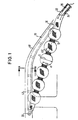
- Fig. 1 is a side impact protection device with a Gas generator 26 and a tubular gas bag 10 shown.
- the Gas bag 10 is with its lateral ends on the one hand at the lower end the A-pillar 40 and on the other hand on the roof frame 42 in the area of the B-pillar attached to a vehicle. Corresponding attachment points are designated with 22 and 20 respectively.
- On the A-pillar 40 is also the Gas generator 26 attached through a gas inlet opening 24 in Airbag 10 protrudes inside.
- the airbag 10 In the non-inflated state, the airbag 10 is under one Cover 28 hidden, as can be seen in FIG. 2.
- the gas bag extends from the attachment point 22 along the A-pillar 40 and the roof frame 42, as in Fig. 1 with dash-dotted lines shown, behind the B-pillar to the fastening point 20.
- the position of the folded gas bag 10 behind the Cladding 28 is made via a plastic sleeve 44, which is an open Has longitudinal end, which faces a side window 46.
- the gas bag 10 periodically shows several constrictions caused by Elements 12 are caused, the gas bag 10 annular surround.
- the elements 12 consist of one as small as possible stretchable fabric tape, which is attached to the wall of the gas bag 10 is.
- the elements 12 can also be made of plastic or be woven into the gas bag wall. It is also possible that a wall section 10 especially woven in the area of the elements 12 is, so that it is not inflated in this area total airbag diameter D, but a reduced diameter d can take, which is about a third of the maximum Diameter D in the area not constricted.
- the weaving direction of the wall consisting of a textile fabric runs at 45 ° to the longitudinal direction of the gas bag 10 and promotes thereby shortening the gas bag 10 in during inflation Longitudinal direction together with the elements 12.
- gas generator 26 flows generated gas into the interior of the gas bag 10.
- the gas bag 10 is shortened in the longitudinal direction so that it has the attachment points 20, 22 bridged the shortest possible path. Between the individual elements 12 result, depending on the distance between the elements 12, spherical or cylindrical sections.
- the elements 12 do not have to be arranged at regular intervals but should be on the mounting points 20, 22 and Gas generator mounting and the seating position in relation to Gas bag position to be matched. It can also be different Elements 12 are used, the gas bag 10 at different Constrict areas of varying degrees. In the area of the head one A less severe constriction is advantageous for vehicle occupants, while e.g. to the attachment points 20, 22 stronger Constrictions can be provided.
- the gas bag shown in Fig. 1 10 does not need the side window as a support because it is in Braced in the longitudinal direction between the fastening points 20 and 22 is.
- the gas bag 10 is not designed like a tube, but rather like a pillow. It extends in the inflated state from the lower end of the A-pillar 40 to the B-pillar and is hidden under a cover 28 in the non-inflated state, according to FIG. 2. It is also built into the vehicle in an arc shape. In contrast to the embodiment shown in FIG. 1, however, more than two fastening points 20, 22 are provided. When the gas bag 10 unfolds, it shortens mainly in the area of its lower edge so much due to a cord woven into the gas bag wall as a constricting element 50 that the gas bag 10 tears the cover 28 out of its fastening and the outermost fastening points 20, 22 on a shorter one Bridged way. Another difference between the FIGS. 1 and 2 and the embodiment shown in FIG. 3 is that the constricting element 50 does not surround the pillow-shaped gas bag 10 according to FIG. 3, so that only the lower edge region constricts.
- Both embodiments have in common that the constricting elements 12, 50 substantially transversely to the longitudinal direction of the gas bag 10 extend.
- the elements 12, 50 can also be used as on the roof frame 42 fastened ribbons or cords that are formed the lower Constrict the edge area of the gas bag 10. This embodiment however, requires a larger assembly effort.
Landscapes
- Engineering & Computer Science (AREA)
- Mechanical Engineering (AREA)
- Air Bags (AREA)
- Sampling And Sample Adjustment (AREA)
- Cooling, Air Intake And Gas Exhaust, And Fuel Tank Arrangements In Propulsion Units (AREA)
Applications Claiming Priority (3)
| Application Number | Priority Date | Filing Date | Title |
|---|---|---|---|
| DE29605897U DE29605897U1 (de) | 1996-03-29 | 1996-03-29 | Gassack |
| DE29605897U | 1996-03-29 | ||
| EP97104571A EP0798173B1 (de) | 1996-03-29 | 1997-03-18 | Gassack mit quer zur Längsrichtung einschnürenden Elementen |
Related Parent Applications (1)
| Application Number | Title | Priority Date | Filing Date |
|---|---|---|---|
| EP97104571A Division EP0798173B1 (de) | 1996-03-29 | 1997-03-18 | Gassack mit quer zur Längsrichtung einschnürenden Elementen |
Publications (2)
| Publication Number | Publication Date |
|---|---|
| EP0957008A1 EP0957008A1 (de) | 1999-11-17 |
| EP0957008B1 true EP0957008B1 (de) | 2001-08-29 |
Family
ID=8021927
Family Applications (2)
| Application Number | Title | Priority Date | Filing Date |
|---|---|---|---|
| EP99116760A Expired - Lifetime EP0957008B1 (de) | 1996-03-29 | 1997-03-18 | Seitenaufprall-Schutzeinrichtung |
| EP97104571A Expired - Lifetime EP0798173B1 (de) | 1996-03-29 | 1997-03-18 | Gassack mit quer zur Längsrichtung einschnürenden Elementen |
Family Applications After (1)
| Application Number | Title | Priority Date | Filing Date |
|---|---|---|---|
| EP97104571A Expired - Lifetime EP0798173B1 (de) | 1996-03-29 | 1997-03-18 | Gassack mit quer zur Längsrichtung einschnürenden Elementen |
Country Status (9)
| Country | Link |
|---|---|
| US (1) | US5941564A (cs) |
| EP (2) | EP0957008B1 (cs) |
| JP (1) | JP2916437B2 (cs) |
| KR (1) | KR100211396B1 (cs) |
| CN (1) | CN1171339A (cs) |
| CZ (1) | CZ96197A3 (cs) |
| DE (3) | DE29605897U1 (cs) |
| ES (2) | ES2107407T3 (cs) |
| TW (1) | TW344722B (cs) |
Families Citing this family (49)
| Publication number | Priority date | Publication date | Assignee | Title |
|---|---|---|---|---|
| DE29517373U1 (de) * | 1995-11-02 | 1996-03-07 | Trw Repa Gmbh | Gassack-Seitenaufprall-Schutzeinrichtung für Fahrzeuginsassen |
| DE29517953U1 (de) * | 1995-11-13 | 1995-12-21 | Trw Repa Gmbh | Knieschutzeinrichtung |
| DE19612227A1 (de) * | 1996-03-27 | 1997-10-02 | Bayerische Motoren Werke Ag | Anordnung eines aufblasbaren Kopfschutzsystemes in einem Kraftfahrzeug |
| DE19612228A1 (de) | 1996-03-27 | 1997-10-02 | Bayerische Motoren Werke Ag | Aufblasbares Kopfschutzsystem für den Seitenbereich eines Personenkraftwagens |
| DE19612229A1 (de) * | 1996-03-27 | 1997-10-02 | Bayerische Motoren Werke Ag | Anordnung eines aufblasbaren seitlichen Kopfschutzsystemes in einem Kraftfahrzeug |
| ATE197025T1 (de) * | 1996-06-23 | 2000-11-15 | Hs Tech & Design | Airbagvorrichtung |
| JP3069601B2 (ja) | 1996-10-03 | 2000-07-24 | 東洋ゴム工業株式会社 | 側部用エアバッグ |
| CA2242339C (en) | 1996-11-07 | 2002-07-09 | Toyota Jidosha Kabushiki Kaisha | Arrangement and construction of crew protective device for automobile |
| GB2319751B (en) * | 1996-11-22 | 2001-04-04 | Autoliv Dev | Improvements in or relating to an air-bag arrangement |
| DE19752989B4 (de) * | 1996-12-02 | 2005-11-10 | Toyoda Gosei Co., Ltd. | Seitenairbag-Vorrichtung |
| JP3858325B2 (ja) * | 1997-01-16 | 2006-12-13 | 豊田合成株式会社 | 側部用エアバッグ装置 |
| US6082761A (en) * | 1997-01-24 | 2000-07-04 | Toyoda Gosei Co., Ltd. | Side airbag device |
| GB2324068B (en) * | 1997-04-11 | 2001-01-10 | Autoliv Dev | Improvements in or relating to an air-bag arrangement |
| DE19718203A1 (de) * | 1997-04-30 | 1998-11-05 | Daimler Benz Ag | Airbagvorhang, insbesondere für eine Fahrzeugscheibe |
| DE29709389U1 (de) * | 1997-05-28 | 1997-09-25 | Trw Repa Gmbh | Gassack für ein Insassen-Rückhaltesystem in Fahrzeugen |
| DE29720619U1 (de) | 1997-11-20 | 1999-05-12 | Lear Corp Gmbh & Co Kg | Seitenaufprall-Schutzeinrichtung |
| DE19757374A1 (de) * | 1997-12-22 | 1999-06-24 | Takata Europ Gmbh | Sicherheitsvorrichtung für ein Kraftfahrzeug |
| GB2333071B (en) * | 1998-01-13 | 2002-01-23 | Autoliv Dev | Improvements in or relating to a safety arrangement |
| DE29802507U1 (de) * | 1998-02-13 | 1998-06-10 | Trw Repa Gmbh | Rückhaltevorrichtung mit Spanneinrichtung |
| JPH11348721A (ja) * | 1998-06-08 | 1999-12-21 | Takata Kk | エアベルト及びエアベルト装置 |
| JP2000006752A (ja) * | 1998-06-17 | 2000-01-11 | Takata Kk | 頭部拘束用サイドエアバッグ |
| US6152481A (en) * | 1998-08-03 | 2000-11-28 | Delphi Technologies, Inc. | Side restraint assembly |
| US6109834A (en) * | 1998-08-28 | 2000-08-29 | Texaco Inc. | Composite tubular and methods |
| US6179324B1 (en) | 1999-01-11 | 2001-01-30 | Trw Vehicle Safety Systems Inc. | Vehicle inflatable side curtain assembly |
| EP1156949A1 (en) * | 1999-01-12 | 2001-11-28 | Autoliv Development Ab | An air-bag and a method of deploying an air-bag |
| DE29907622U1 (de) | 1999-04-29 | 1999-09-23 | Trw Repa Gmbh | Seitengassack-Rückhaltesystem |
| JP2001047962A (ja) * | 1999-08-09 | 2001-02-20 | Takata Corp | 自動車乗員頭部の保護バッグ、保護装置及び自動車 |
| US6398253B1 (en) * | 1999-09-01 | 2002-06-04 | Trw Occupant Restraint Systems Gmbh & Co. Kg | Gas bag protective device |
| US6276712B1 (en) * | 1999-09-10 | 2001-08-21 | Delphi Technologies, Inc. | Side restraint assembly for an automotive vehicle |
| DE10109500A1 (de) * | 2000-03-03 | 2001-10-04 | Takata Corp | Kopfschutzkissen für Fahrzeuginsassen |
| US6237942B1 (en) | 2000-07-14 | 2001-05-29 | Trw Inc. | Inflatable vehicle occupant protection device |
| US6612611B1 (en) | 2000-08-29 | 2003-09-02 | Trw Inc. | Door mounted inflatable tubular structure |
| DE20016471U1 (de) | 2000-09-22 | 2001-02-22 | Trw Repa Gmbh | Seitengassack-Rückhaltesystem |
| US7093851B2 (en) * | 2001-03-13 | 2006-08-22 | Delphi Technologies, Inc. | Tunable control side air bag cushion |
| US6709008B2 (en) | 2001-11-19 | 2004-03-23 | Autoliv Asp, Inc. | Retractable tethering device for curtain airbag |
| US6695347B2 (en) | 2001-11-29 | 2004-02-24 | Autoliv Asp, Inc. | Self-adjusting tether strap for inflatable curtain |
| US7025378B2 (en) * | 2003-07-10 | 2006-04-11 | Milliken & Company | Air bag and method for making an air bag |
| US20050184492A1 (en) * | 2004-02-20 | 2005-08-25 | Shilliday David M. | Inflatable cushioning devices |
| KR100567208B1 (ko) * | 2004-06-03 | 2006-04-07 | 장세창 | 타수계가 구비된 관절형 골프티 |
| CN1295107C (zh) * | 2004-07-29 | 2007-01-17 | 湖南大学 | 管式复合安全气囊 |
| JP4535060B2 (ja) * | 2006-11-30 | 2010-09-01 | タカタ株式会社 | 自動車乗員頭部の保護バッグ、保護装置及び自動車 |
| JP5230861B2 (ja) * | 2007-06-28 | 2013-07-10 | 日本プラスト株式会社 | カーテンエアバッグ装置 |
| JP5033571B2 (ja) * | 2007-10-16 | 2012-09-26 | タカタ株式会社 | エアバッグ装置 |
| DE102008026818A1 (de) | 2008-06-05 | 2009-12-10 | GM Global Technology Operations, Inc., Detroit | Rückhaltevorrichtung für eine Seitenfläche eines Fahrzeugs |
| GB2473608B (en) * | 2009-09-14 | 2014-11-26 | Ford Global Tech Llc | An airbag tether connector assembly and a curtain airbag assembly |
| JP5244776B2 (ja) * | 2009-12-24 | 2013-07-24 | 本田技研工業株式会社 | エアバッグ装置 |
| US9283917B2 (en) * | 2011-04-28 | 2016-03-15 | Autoliv Development Ab | Curtain airbag device |
| US8556291B2 (en) * | 2011-07-06 | 2013-10-15 | Zodiac Seats France | Airbag in privacy wall |
| CN106143388A (zh) * | 2016-07-13 | 2016-11-23 | 芜湖金鹏汽车部件有限公司 | 汽车安全装置 |
Family Cites Families (21)
| Publication number | Priority date | Publication date | Assignee | Title |
|---|---|---|---|---|
| US2806737A (en) * | 1955-04-11 | 1957-09-17 | Paul M Maxwell | Inflatable collision shield for vehicles |
| BR7205321D0 (pt) * | 1971-08-25 | 1973-09-25 | Addressograph Multigraph | Dispositivo para a separacao de cilindros sensivel a introducao de folhas a serem impressas numa maquina de impressao offset |
| US3888503A (en) * | 1973-02-22 | 1975-06-10 | Allied Chem | Limiting of continuous extent of inflatable restraint |
| JPS5037131A (cs) * | 1973-08-07 | 1975-04-07 | ||
| IT1061177B (it) * | 1976-03-25 | 1982-10-20 | Exacon Int | Dispositivo protettivo per la testa di automobilisti |
| JPH04228648A (ja) * | 1990-12-27 | 1992-08-18 | Bridgestone Corp | エアバッグ |
| DE4137749A1 (de) * | 1991-11-15 | 1993-05-19 | Kolbenschmidt Ag | Sicherheitsvorrichtung |
| JPH05147310A (ja) * | 1991-11-30 | 1993-06-15 | Nec Corp | 印字媒体位置決め制御装置 |
| JP3186163B2 (ja) * | 1992-01-31 | 2001-07-11 | タカタ株式会社 | 車両乗員の保護装置 |
| DE4307175C2 (de) * | 1992-03-18 | 2002-02-28 | Volkswagen Ag | Insassen-Seitenschutz für ein Kraftfahrzeug |
| JP3113081B2 (ja) * | 1992-08-18 | 2000-11-27 | タカタ株式会社 | インフレータブルシートベルト装置 |
| CA2123424C (en) * | 1992-09-14 | 1999-04-06 | Kunio Nishimura | Air bag provided with reinforcing belts |
| US5322322A (en) * | 1993-02-19 | 1994-06-21 | Simula Inc. | Side impact head strike protection system |
| US5480181A (en) * | 1993-02-19 | 1996-01-02 | Simula Inc. | Side impact head strike protection system |
| JPH06344841A (ja) * | 1993-06-11 | 1994-12-20 | Honda Motor Co Ltd | 車両用乗員保護装置 |
| JPH07117605A (ja) * | 1993-10-27 | 1995-05-09 | Honda Motor Co Ltd | 自動車用エアバッグ装置 |
| DE19519297A1 (de) * | 1994-06-03 | 1995-12-07 | Volkswagen Ag | Sicherheitseinrichtung für ein Fahrzeug |
| JPH0826063A (ja) * | 1994-07-19 | 1996-01-30 | Nissan Motor Co Ltd | エアバッグ装置 |
| JPH0853041A (ja) * | 1994-08-10 | 1996-02-27 | Honda Motor Co Ltd | 自動車用エアバッグ装置 |
| US5602734A (en) * | 1994-09-23 | 1997-02-11 | Advanced Safety Concepts, Inc. | Automobile air bag systems |
| DE4436139C1 (de) * | 1994-10-10 | 1996-03-21 | Autoliv Dev | Fahrgastsitz mit Seitenaufprallschutz |
-
1996
- 1996-03-29 DE DE29605897U patent/DE29605897U1/de not_active Expired - Lifetime
-
1997
- 1997-03-11 TW TW086102993A patent/TW344722B/zh active
- 1997-03-18 EP EP99116760A patent/EP0957008B1/de not_active Expired - Lifetime
- 1997-03-18 EP EP97104571A patent/EP0798173B1/de not_active Expired - Lifetime
- 1997-03-18 ES ES97104571T patent/ES2107407T3/es not_active Expired - Lifetime
- 1997-03-18 DE DE59702872T patent/DE59702872D1/de not_active Expired - Lifetime
- 1997-03-18 DE DE59704482T patent/DE59704482D1/de not_active Expired - Lifetime
- 1997-03-18 ES ES99116760T patent/ES2162505T3/es not_active Expired - Lifetime
- 1997-03-25 US US08/824,229 patent/US5941564A/en not_active Expired - Lifetime
- 1997-03-28 KR KR1019970011016A patent/KR100211396B1/ko not_active Expired - Fee Related
- 1997-03-28 CZ CZ97961A patent/CZ96197A3/cs unknown
- 1997-03-28 CN CN97109932A patent/CN1171339A/zh active Pending
- 1997-03-28 JP JP9077915A patent/JP2916437B2/ja not_active Expired - Lifetime
Also Published As
| Publication number | Publication date |
|---|---|
| ES2162505T3 (es) | 2001-12-16 |
| DE29605897U1 (de) | 1996-07-25 |
| DE59704482D1 (de) | 2001-10-04 |
| EP0798173A1 (de) | 1997-10-01 |
| ES2107407T1 (es) | 1997-12-01 |
| EP0798173B1 (de) | 2001-01-10 |
| ES2107407T3 (es) | 2001-04-01 |
| KR100211396B1 (en) | 1999-08-02 |
| DE59702872D1 (de) | 2001-02-15 |
| JP2916437B2 (ja) | 1999-07-05 |
| EP0957008A1 (de) | 1999-11-17 |
| TW344722B (en) | 1998-11-11 |
| CN1171339A (zh) | 1998-01-28 |
| CZ96197A3 (cs) | 1999-08-11 |
| JPH106900A (ja) | 1998-01-13 |
| US5941564A (en) | 1999-08-24 |
Similar Documents
| Publication | Publication Date | Title |
|---|---|---|
| EP0957008B1 (de) | Seitenaufprall-Schutzeinrichtung | |
| EP1048531B1 (de) | Seitenaufprall-Schutzeinrichtung für Fahrzeuginsassen | |
| DE60207393T2 (de) | Airbagvorrichtung zum schutz von fussgängern | |
| DE69717593T2 (de) | Aufblasbare Schutzeinrichtung für Fahrzeuginsassen | |
| DE69831040T2 (de) | Kopfschutzende Airbagvorrichtung | |
| EP0791511B1 (de) | Seitenaufprall-Schutzeinrichtung für Fahrzeuginsassen | |
| DE60223164T2 (de) | Seitenaufprall-airbagvorrichtung | |
| DE102006054387B4 (de) | Kollisionsobjekt-Schutzvorrichtung | |
| DE102013221983B4 (de) | Vorhangairbag für ein Fahrzeug sowie eine Rückhalteanordnung | |
| DE10000768B4 (de) | Aufblasbare Seitenvorhanganordnung für ein Fahrzeug | |
| DE102005011676B4 (de) | Vorhang-Gassack und Kraftfahrzeug | |
| DE10306343B4 (de) | Insassenschutzeinrichtung | |
| DE102005002085A1 (de) | Seitenairbageinrichtung | |
| EP1058633B1 (de) | Gassack-modul | |
| EP1053132A1 (de) | Rückhaltevorrichtung mit spanneinrichtung | |
| DE19843402C1 (de) | Seitenaufprall-Airbageinrichtung | |
| EP1059209B1 (de) | Schutzvorrichtung für den Kopf- und Schulterbereich von Fahrzeuginsassen | |
| EP0889808B1 (de) | Aufblasbares kopfschutzsystem für den seitenbereich eines personenkraftwagens | |
| DE19547494C2 (de) | Schutzeinrichtung für die Insassen eines Kraftfahrzeuges | |
| DE10140363B4 (de) | An der Tür angebrachte rohrförmige Struktur | |
| DE29907622U1 (de) | Seitengassack-Rückhaltesystem | |
| EP0878359A1 (de) | Seitenaufprallschutzeinrichtung für einen Insassen eines Fahrzeuges | |
| EP1182099B1 (de) | Fahrzeuginsassen-Schutzvorrichtung mit Seitengassack | |
| DE102005044563B4 (de) | Seitenairbag mit definierter Entfaltungsrichtung | |
| EP0947393A1 (de) | Gassack-Rückhaltesystem |
Legal Events
| Date | Code | Title | Description |
|---|---|---|---|
| PUAI | Public reference made under article 153(3) epc to a published international application that has entered the european phase |
Free format text: ORIGINAL CODE: 0009012 |
|
| AC | Divisional application: reference to earlier application |
Ref document number: 798173 Country of ref document: EP |
|
| AK | Designated contracting states |
Kind code of ref document: A1 Designated state(s): DE ES FR GB IT SE |
|
| AX | Request for extension of the european patent |
Free format text: AL;LT;LV;RO;SI |
|
| 17P | Request for examination filed |
Effective date: 20000308 |
|
| AKX | Designation fees paid |
Free format text: DE ES FR GB IT SE |
|
| 17Q | First examination report despatched |
Effective date: 20000711 |
|
| GRAG | Despatch of communication of intention to grant |
Free format text: ORIGINAL CODE: EPIDOS AGRA |
|
| RTI1 | Title (correction) |
Free format text: SIDE IMPACT PROTECTION APPARATUS |
|
| GRAG | Despatch of communication of intention to grant |
Free format text: ORIGINAL CODE: EPIDOS AGRA |
|
| GRAH | Despatch of communication of intention to grant a patent |
Free format text: ORIGINAL CODE: EPIDOS IGRA |
|
| GRAH | Despatch of communication of intention to grant a patent |
Free format text: ORIGINAL CODE: EPIDOS IGRA |
|
| GRAA | (expected) grant |
Free format text: ORIGINAL CODE: 0009210 |
|
| AC | Divisional application: reference to earlier application |
Ref document number: 798173 Country of ref document: EP |
|
| AK | Designated contracting states |
Kind code of ref document: B1 Designated state(s): DE ES FR GB IT SE |
|
| REF | Corresponds to: |
Ref document number: 59704482 Country of ref document: DE Date of ref document: 20011004 |
|
| GBT | Gb: translation of ep patent filed (gb section 77(6)(a)/1977) |
Effective date: 20011117 |
|
| ET | Fr: translation filed | ||
| REG | Reference to a national code |
Ref country code: ES Ref legal event code: FG2A Ref document number: 2162505 Country of ref document: ES Kind code of ref document: T3 |
|
| REG | Reference to a national code |
Ref country code: GB Ref legal event code: IF02 |
|
| PG25 | Lapsed in a contracting state [announced via postgrant information from national office to epo] |
Ref country code: GB Free format text: LAPSE BECAUSE OF NON-PAYMENT OF DUE FEES Effective date: 20020318 |
|
| PG25 | Lapsed in a contracting state [announced via postgrant information from national office to epo] |
Ref country code: SE Free format text: LAPSE BECAUSE OF NON-PAYMENT OF DUE FEES Effective date: 20020319 Ref country code: ES Free format text: LAPSE BECAUSE OF NON-PAYMENT OF DUE FEES Effective date: 20020319 |
|
| PLBE | No opposition filed within time limit |
Free format text: ORIGINAL CODE: 0009261 |
|
| STAA | Information on the status of an ep patent application or granted ep patent |
Free format text: STATUS: NO OPPOSITION FILED WITHIN TIME LIMIT |
|
| 26N | No opposition filed | ||
| EUG | Se: european patent has lapsed |
Ref document number: 99116760.2 |
|
| GBPC | Gb: european patent ceased through non-payment of renewal fee |
Effective date: 20020318 |
|
| REG | Reference to a national code |
Ref country code: ES Ref legal event code: FD2A Effective date: 20030410 |
|
| REG | Reference to a national code |
Ref country code: FR Ref legal event code: PLFP Year of fee payment: 20 |
|
| PGFP | Annual fee paid to national office [announced via postgrant information from national office to epo] |
Ref country code: FR Payment date: 20160328 Year of fee payment: 20 |
|
| PGFP | Annual fee paid to national office [announced via postgrant information from national office to epo] |
Ref country code: DE Payment date: 20160331 Year of fee payment: 20 |
|
| PGFP | Annual fee paid to national office [announced via postgrant information from national office to epo] |
Ref country code: IT Payment date: 20160323 Year of fee payment: 20 |
|
| REG | Reference to a national code |
Ref country code: DE Ref legal event code: R071 Ref document number: 59704482 Country of ref document: DE |