EP0956929A2 - Dispositif pour la coupe d'un produit en morceaux cunéiformes - Google Patents
Dispositif pour la coupe d'un produit en morceaux cunéiformes Download PDFInfo
- Publication number
- EP0956929A2 EP0956929A2 EP99104896A EP99104896A EP0956929A2 EP 0956929 A2 EP0956929 A2 EP 0956929A2 EP 99104896 A EP99104896 A EP 99104896A EP 99104896 A EP99104896 A EP 99104896A EP 0956929 A2 EP0956929 A2 EP 0956929A2
- Authority
- EP
- European Patent Office
- Prior art keywords
- cutting
- cutting means
- wedge
- cheese
- transport
- Prior art date
- Legal status (The legal status is an assumption and is not a legal conclusion. Google has not performed a legal analysis and makes no representation as to the accuracy of the status listed.)
- Granted
Links
Images

Classifications
-
- B—PERFORMING OPERATIONS; TRANSPORTING
- B26—HAND CUTTING TOOLS; CUTTING; SEVERING
- B26D—CUTTING; DETAILS COMMON TO MACHINES FOR PERFORATING, PUNCHING, CUTTING-OUT, STAMPING-OUT OR SEVERING
- B26D3/00—Cutting work characterised by the nature of the cut made; Apparatus therefor
- B26D3/24—Cutting work characterised by the nature of the cut made; Apparatus therefor to obtain segments other than slices, e.g. cutting pies
Definitions
- the invention relates to a device for cutting one on one Base of the object lying on it in wedge-shaped pieces.
- Such an object can, for example, be an im essential block-shaped cheese bars act in wedge-shaped pieces should be cut because a wedge shape of the pieces - instead of one purely rectangular shape - acceptance by potential buyers of this Increase pieces and can thus promote sales.
- a piece is generally referred to as wedge-shaped a substantially trapezoidal side or cross-sectional area has, that is, an area whose outline two substantially parallel and two essentially angled boundaries having.
- this object is achieved on the one hand by a device with a cutting means which by means of a drive means to a Cutting movement can be driven within a cutting plane, which is substantially perpendicular to the base, and a means of transport, through which the object and the cutting means in one Transport direction are movable relative to each other, the cutting plane of the cutting means is pivotable about a pivot axis that is perpendicular to the base.
- the device according to the invention thus has a cutting means, for example a knife through which individual pieces of the object can be cut off, the cutting movement perpendicular to the base of the device on which the object rests.
- a cutting means for example a knife through which individual pieces of the object can be cut off, the cutting movement perpendicular to the base of the device on which the object rests.
- Another piece can be cut off from the item, after the object and the cutting means through the means of transport be moved relative to each other.
- the pieces can come in different Angular positions of the cutting means and thus wedge-shaped can be cut from the object because the cutting means in different pivot positions is pivotable that its cutting plane is still perpendicular to the base in any swivel position.
- the device of the invention has the advantage that it is also in the essential purely rectangular objects an individual and thus enables precise weight cutting into wedge-shaped pieces.
- At known dimensions and weight or density of the object can wedge-shaped pieces of a predetermined weight the object can be cut, or the object can be cut into a predetermined number of wedge-shaped pieces that are cut each have the same weight.
- Another advantage of the device according to the invention is that that the sequential cutting of the object into wedge-shaped Pieces allows sequential processing and thus one automated processing of these pieces easier. Because the pieces - in contrast to the simultaneous cutting of an object using a wire mesh - cut individually from the object, you can immediately after the cutting process be separated in a simple manner, in particular mechanically, i.e. be removed from the remaining item. You can also the wedge-shaped cut sequentially from the object Pieces of a downstream processing device, for example a device for packaging these pieces, with essentially constant transport rate can be supplied.
- the device is preferably designed such that the pivot axis of the cutting means substantially half the width of the base is arranged, on which the object rests for cutting, the width of this base area being its direction of extension, the perpendicular to the direction of transport of the cutting material and object runs.
- the cutting means is pivoted especially around its central axis. This configuration of the device enables - when moving the object and the cutting means relative to each other by essentially the same feed distance - cutting a rectangular object into equal sizes wedge-shaped pieces (see Fig. 4).
- a particularly simple construction of the device can be achieved if exactly two for pivoting the cutting plane of the cutting means Swivel positions are provided, the cutting means in one of these two swivel positions, preferably perpendicular to the transport direction, i.e. extends parallel to the width of the base.
- a higher one Flexibility of the device in terms of shape or weight Pieces can be reached if for the cutting plane of the cutting means in contrast, a variety of discrete swivel positions or variable Swivel positions are provided.
- At least one actuating element can be provided, which in particular a hydraulic or pneumatic cylinder, a lever, one has mechanical cam drive or a servo drive.
- a counter pressure element for this actuating element for example, a spring provided.
- the cutting means is designed as a guillotine blade is, for example, pivotally held within a frame or is fixedly mounted within a pivotable frame, wherein the frame by means of the drive means for performing the cutting movement of the cutting means can be driven.
- the device according to the invention can be used as a drive means for the Cutting means have one or more crank rods that the Base area are arranged substantially adjacent. Especially it is possible to use a guillotine blade within a frame Actuator to pivot and mount the frame by means of the crank rods to move parallel to the cutting plane to drive.
- At least one is the means of transport of the device according to the invention Conveyor belt provided through which the object in the direction of transport is moved.
- the cutting medium leads in the transport direction no own movement, it just becomes the cutting movement driven.
- a conveyor belt as Transport means forms part of this conveyor belt each Base area on which the object to be cut rests.
- Another object of the invention is achieved by a method, by the in a device described above in essentially alternating steps the cutting medium around the Swiveled axis pivoted and a wedge-shaped by means of the cutting means Piece is cut from the object, and on the other hand the Object and the cutting means around a feed distance in the transport direction be moved relative to each other.
- the swiveling of the cutting means can either be in front of or after the assigned cutting movement, and it can be parallel to a movement of the object and the cutting means relative to each other be performed.
- the feed distance, around which the object and cutting means are relative are moved towards each other for an object to be cut in is essentially the same size. This enables a particularly simple one Driving the relative transport movement and a comparative uniform rate at which pieces are cut and transported become.
- an item is related to its being cut up the transport direction is aligned and / or centered. Furthermore can cut the weight and dimensions before cutting of the object can be determined. Through these measures, the cutting of the object into wedge-shaped pieces a special high weight accuracy can be achieved.
- the device or the subject-matter of the method according to the invention may be is a food product, especially a cheese bar.
- This The object is preferably rectangular, i.e. he has at least one rectangular side surface.
- the item only has a rectangular cross-sectional area while he appears cylindrical from the outside, for example.
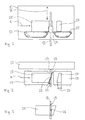
- FIG. 1 and 2 show a schematic front view and plan view Parts of a cutting device according to the invention.
- This has one Control and drive unit 11, and an endless infeed belt 13 and an endless discharge belt 15, which in the figures only by their axes of rotation indicated drive shafts with the control and drive unit 11 are connected.
- the respective tops of the two Belts 13, 15 are independent by means of the control and drive unit 11 from each other to a transport movement in the horizontal Transport direction A can be driven.
- a frame 17 as the cutting means provided, in the center of which a blade 19 is arranged, which at its Underside has a cutting surface.
- the frame 17 together with the blade 19 is arranged within the control and drive unit 11 Crank rod can be driven for a vertical cutting movement B.
- Fig. 1 shows the frame 17 in its lowest position.
- the top view 2 the frame 17 is aligned perpendicular to the transport direction A.
- FIG. 5 shows the frame 17 and the blade 19 in a schematic side view.
- the blade 19 is by means of a not shown in the figures Actuator with respect to the frame 17 about its vertical central axis 21 swiveling, i.e. the central axis 21 forms the pivot axis the cutting plane of the blade 19.
- the top view of FIG. 2 shows how the Blade 19 pivoted out of the frame 17 by a pivot angle 23 is.
- FIG. 1 and 2 also show a substantially cuboid Cheese bar 25, from which a wedge-shaped piece 27 has already been cut off and the rest of it on the top of the infeed conveyor 13 rests.
- the wedge-shaped already cut from the cheese bar 25 Piece 27 is on the top of the discharge belt 15.
- the pivoted by the pivot angle 23 position of the blade 19 in the plan view according to FIG. 2 close the blade 19 facing each Side surface of both the cheese bar 25 and the piece of cheese 27 with the plane of extension of the frame 17, the pivot angle 23 on.
- FIGS. 1 and 2 can be used according to the following inventive method wedge-shaped pieces from the Cut cheese bar 25:
- To cut into pieces 27 with precise weight enable, will also be its length in the transport direction A and determines its total weight.
- the cheese bar 25 - while the frame 17 together with the blade 19 are in an upper position located - so moved in the direction of transport A that its with respect the transport direction A front section by a feed distance 29 protrudes below the blade 19 through the frame 17.
- This Cheese piece 27 is in the transport direction by means of the discharge belt 15 A transported further. The state thus achieved corresponds to that in the 1 and 2 position of the blade 19, the cheese bar 25 and the Piece of cheese 27.
- the entire cheese bar 25 can be made according to a cutting pattern be cut into wedge-shaped pieces of cheese 27, as shown in Fig. 4 in schematic plan view for the reassembled from the pieces of cheese 27 Cheese bar 25 is shown.
- Each piece has 27 in Top view the outline of a trapezoid with two right angles 31.
- Two Adjacent, cut apart by means of pivoted blade 19 Pieces 27 complement each other to form a rectangular outline.
- the cheese bar 25 shown in Fig. 4 and, accordingly, the pieces 27 have the width 33 and along perpendicular to the transport direction A. the transport direction A with respect to this width 33 the longitudinal center axis 35.
- the invention thus advantageously enables the cutting of a rectangular cheese bar 25 into wedge-shaped pieces 27. Since the cutting these pieces 27 of the cheese bar 25 one by one takes place, the cheese bar 25 can be cut to the exact weight. Especially it is possible to lock the latch 25 in a predetermined number of Cut pieces 27 each of the same weight. Because the cheese bar 25 with its central longitudinal axis 35 through that serving as the pivot axis The central axis 21 of the blade 19 is guided, the bolt 25 can are moved by the same feed distance 29 in each case.
- FIG. 6 shows one as shown 2 corresponding schematic top view of a frame 17 with such an articulated along a lateral pivot axis 37 Blade 19.
Applications Claiming Priority (2)
| Application Number | Priority Date | Filing Date | Title |
|---|---|---|---|
| DE19821753A DE19821753A1 (de) | 1998-05-14 | 1998-05-14 | Vorrichtung zum Zerschneiden eines Gegenstandes in keilförmige Stücke |
| DE19821753 | 1998-05-14 |
Publications (4)
| Publication Number | Publication Date |
|---|---|
| EP0956929A2 true EP0956929A2 (fr) | 1999-11-17 |
| EP0956929A3 EP0956929A3 (fr) | 2002-05-22 |
| EP0956929B1 EP0956929B1 (fr) | 2004-07-07 |
| EP0956929B2 EP0956929B2 (fr) | 2009-02-18 |
Family
ID=7867827
Family Applications (1)
| Application Number | Title | Priority Date | Filing Date |
|---|---|---|---|
| EP99104896A Expired - Lifetime EP0956929B2 (fr) | 1998-05-14 | 1999-03-11 | Dispositif pour la coupe d'un produit en morceaux cunéiformes |
Country Status (3)
| Country | Link |
|---|---|
| EP (1) | EP0956929B2 (fr) |
| AT (1) | ATE270606T1 (fr) |
| DE (2) | DE19821753A1 (fr) |
Cited By (2)
| Publication number | Priority date | Publication date | Assignee | Title |
|---|---|---|---|---|
| EP1525961A1 (fr) * | 2003-10-20 | 2005-04-27 | Kraft Foods Holdings, Inc. | Dispositif pour couper a l'aide des ultrasons |
| FR2938462A1 (fr) * | 2008-11-14 | 2010-05-21 | Ermatec | Machine de decoupe de produit agroalimentaire |
Families Citing this family (1)
| Publication number | Priority date | Publication date | Assignee | Title |
|---|---|---|---|---|
| DE102019122994A1 (de) * | 2019-08-27 | 2021-03-04 | Weber Maschinenbau Gmbh Breidenbach | Käseteiler und Verfahren zum Messen einer Länge eines Käseprodukts |
Citations (6)
| Publication number | Priority date | Publication date | Assignee | Title |
|---|---|---|---|---|
| DE116393C (fr) † | ||||
| GB689441A (en) * | 1950-07-21 | 1953-03-25 | E P Lawson Co Inc | Improvements in or relating to paper cutters of the guillotine type |
| DE1038726B (de) † | 1956-03-26 | 1958-09-11 | Emil Doll K G Fahrzeug Und Kar | Kaeseschneider |
| US4554852A (en) * | 1983-07-26 | 1985-11-26 | Food Equipment Manufacturing Corporation | Cutting machine for slicing circular articles into wedges |
| US4817465A (en) * | 1986-12-23 | 1989-04-04 | Food Tools, Inc. | Rotary table for bakery product slicer |
| WO1995030518A1 (fr) † | 1994-05-05 | 1995-11-16 | Unilever Plc | Procede de division d'un bloc d'aliments en portions |
Family Cites Families (6)
| Publication number | Priority date | Publication date | Assignee | Title |
|---|---|---|---|---|
| US3599689A (en) * | 1969-05-19 | 1971-08-17 | Charles James Grant | Apparatus for slicing comestible slabs |
| DE2130515A1 (de) * | 1971-06-19 | 1972-12-21 | Schuppener Siegwerk | Teilvorrichtung |
| AT393645B (de) * | 1988-12-09 | 1991-11-25 | Heinrich Hajek Ges Mbh & Co Ma | Schneidvorrichtung zum portionieren von stueckigen lebens- und nahrungsmitteln, insbesondere von kaese |
| FR2645065B1 (fr) * | 1989-03-29 | 1995-01-13 | Caves Producteurs Reunis | Procede pour trancher en secteurs un produit alimentaire, notamment du type fromage et le dispositif de mise en oeuvre |
| DE19515203A1 (de) * | 1995-04-25 | 1996-10-31 | Alpma Alpenland Masch | Schneidvorrichtung für Lebensmittelprodukte |
| DE19623240C2 (de) * | 1996-06-11 | 2001-04-05 | Sandor Koevy | Anlage zum Zerteilen von auf rechteckförmigen Backblechen flächendeckend befindlicher Backware |
-
1998
- 1998-05-14 DE DE19821753A patent/DE19821753A1/de not_active Withdrawn
-
1999
- 1999-03-11 AT AT99104896T patent/ATE270606T1/de active
- 1999-03-11 DE DE59909884T patent/DE59909884D1/de not_active Expired - Lifetime
- 1999-03-11 EP EP99104896A patent/EP0956929B2/fr not_active Expired - Lifetime
Patent Citations (6)
| Publication number | Priority date | Publication date | Assignee | Title |
|---|---|---|---|---|
| DE116393C (fr) † | ||||
| GB689441A (en) * | 1950-07-21 | 1953-03-25 | E P Lawson Co Inc | Improvements in or relating to paper cutters of the guillotine type |
| DE1038726B (de) † | 1956-03-26 | 1958-09-11 | Emil Doll K G Fahrzeug Und Kar | Kaeseschneider |
| US4554852A (en) * | 1983-07-26 | 1985-11-26 | Food Equipment Manufacturing Corporation | Cutting machine for slicing circular articles into wedges |
| US4817465A (en) * | 1986-12-23 | 1989-04-04 | Food Tools, Inc. | Rotary table for bakery product slicer |
| WO1995030518A1 (fr) † | 1994-05-05 | 1995-11-16 | Unilever Plc | Procede de division d'un bloc d'aliments en portions |
Cited By (2)
| Publication number | Priority date | Publication date | Assignee | Title |
|---|---|---|---|---|
| EP1525961A1 (fr) * | 2003-10-20 | 2005-04-27 | Kraft Foods Holdings, Inc. | Dispositif pour couper a l'aide des ultrasons |
| FR2938462A1 (fr) * | 2008-11-14 | 2010-05-21 | Ermatec | Machine de decoupe de produit agroalimentaire |
Also Published As
| Publication number | Publication date |
|---|---|
| DE19821753A1 (de) | 1999-11-18 |
| ATE270606T1 (de) | 2004-07-15 |
| DE59909884D1 (de) | 2004-08-12 |
| EP0956929B2 (fr) | 2009-02-18 |
| EP0956929B1 (fr) | 2004-07-07 |
| EP0956929A3 (fr) | 2002-05-22 |
Similar Documents
| Publication | Publication Date | Title |
|---|---|---|
| DE7708022U1 (de) | Streifenschneidmaschine | |
| DE60100220T2 (de) | Vorrichtung zur Herstellung eines Stanzmessers | |
| DE2257267A1 (de) | Vorrichtung zum schraegschneiden von bahn- oder streifenfoermigem gummiertem material fuer luftreifenguertellagen | |
| DE102006032659A1 (de) | Vorrichtung und Verfahren zum Aufschneiden einer Matratze | |
| EP1570962A1 (fr) | Machine et méthode à découper des produits alimentaires | |
| EP0867263B1 (fr) | Système d'alimentation de produits dans une machine à débiter en tranches | |
| AT396890B (de) | Vorrichtung zum abstützen eines auf einer plattenaufteilsäge hergestellten langen und schmalen werkstückpakets | |
| EP0963822B1 (fr) | Dispositif et procédé pour le sciage des troncs d'arbres | |
| DE4232289C2 (de) | Verfahren und Vorrichtung zum Verschwenken eines Fensterrahmens im Bereich einer Eckenputzmaschine | |
| DE2413198A1 (de) | Schneidvorrichtung | |
| EP0602308A1 (fr) | Dispositif pour travailler les côtés de pièces en forme de plaques alimentées de façon continue | |
| EP0956929B1 (fr) | Dispositif pour la coupe d'un produit en morceaux cunéiformes | |
| WO2018071950A1 (fr) | Dispositif pour découper des bandes partielles de largeur prédéfinissable | |
| EP4032669A1 (fr) | Machine à trancher à plusieurs pistes pourvue de pinces à commande indépendante | |
| WO1999037161A1 (fr) | Procede et dispositif pour decouper des carcasses et/ou des parties de carcasses de volailles | |
| DE1287790B (fr) | ||
| EP0657259A1 (fr) | Dispositif de coupe pour boudin d'argile | |
| DE2348346C3 (de) | Verfahren und Vorrichtung zum Zusammenbau eines Rolladenpanzers | |
| DE3600965C2 (fr) | ||
| DE3442466C2 (fr) | ||
| DE2414530C3 (de) | Verfahren und Vorrichtung zum Herstellen von gitterartigen Flächenbewehrungen | |
| DE3120961A1 (de) | Kreissaegemaschine | |
| EP0123821B1 (fr) | Appareil pour couper des pièces de travail d'un cordon brut | |
| EP0478530A1 (fr) | Cisaille pour le tronçonnage de grilles en tronçons de longueur choisie à volonté | |
| DE2605234B2 (de) | Messerkopf für eine Gefrierfleischschneidemaschine |
Legal Events
| Date | Code | Title | Description |
|---|---|---|---|
| PUAI | Public reference made under article 153(3) epc to a published international application that has entered the european phase |
Free format text: ORIGINAL CODE: 0009012 |
|
| AK | Designated contracting states |
Kind code of ref document: A2 Designated state(s): AT BE CH CY DE DK ES FI FR GB GR IE IT LI LU MC NL PT SE |
|
| AX | Request for extension of the european patent |
Free format text: AL;LT;LV;MK;RO;SI |
|
| PUAL | Search report despatched |
Free format text: ORIGINAL CODE: 0009013 |
|
| AX | Request for extension of the european patent |
Free format text: AL;LT;LV;MK;RO;SI |
|
| AKX | Designation fees paid | ||
| 17P | Request for examination filed |
Effective date: 20020626 |
|
| RBV | Designated contracting states (corrected) |
Designated state(s): AT DE FR GB IT NL |
|
| REG | Reference to a national code |
Ref country code: DE Ref legal event code: 8566 |
|
| 17Q | First examination report despatched |
Effective date: 20030728 |
|
| GRAP | Despatch of communication of intention to grant a patent |
Free format text: ORIGINAL CODE: EPIDOSNIGR1 |
|
| GRAS | Grant fee paid |
Free format text: ORIGINAL CODE: EPIDOSNIGR3 |
|
| GRAA | (expected) grant |
Free format text: ORIGINAL CODE: 0009210 |
|
| AK | Designated contracting states |
Kind code of ref document: B1 Designated state(s): AT DE FR GB IT NL |
|
| REG | Reference to a national code |
Ref country code: GB Ref legal event code: FG4D Free format text: NOT ENGLISH |
|
| REG | Reference to a national code |
Ref country code: IE Ref legal event code: FG4D Free format text: GERMAN |
|
| REF | Corresponds to: |
Ref document number: 59909884 Country of ref document: DE Date of ref document: 20040812 Kind code of ref document: P |
|
| GBT | Gb: translation of ep patent filed (gb section 77(6)(a)/1977) |
Effective date: 20040909 |
|
| ET | Fr: translation filed | ||
| REG | Reference to a national code |
Ref country code: IE Ref legal event code: FD4D |
|
| PLAQ | Examination of admissibility of opposition: information related to despatch of communication + time limit deleted |
Free format text: ORIGINAL CODE: EPIDOSDOPE2 |
|
| PLAR | Examination of admissibility of opposition: information related to receipt of reply deleted |
Free format text: ORIGINAL CODE: EPIDOSDOPE4 |
|
| PLBQ | Unpublished change to opponent data |
Free format text: ORIGINAL CODE: EPIDOS OPPO |
|
| PLBI | Opposition filed |
Free format text: ORIGINAL CODE: 0009260 |
|
| PLAQ | Examination of admissibility of opposition: information related to despatch of communication + time limit deleted |
Free format text: ORIGINAL CODE: EPIDOSDOPE2 |
|
| PLAR | Examination of admissibility of opposition: information related to receipt of reply deleted |
Free format text: ORIGINAL CODE: EPIDOSDOPE4 |
|
| PLBQ | Unpublished change to opponent data |
Free format text: ORIGINAL CODE: EPIDOS OPPO |
|
| PLAB | Opposition data, opponent's data or that of the opponent's representative modified |
Free format text: ORIGINAL CODE: 0009299OPPO |
|
| PLAX | Notice of opposition and request to file observation + time limit sent |
Free format text: ORIGINAL CODE: EPIDOSNOBS2 |
|
| 26 | Opposition filed |
Opponent name: DOEINGHAUS MASCHINENBAU GMBH Effective date: 20050406 |
|
| R26 | Opposition filed (corrected) |
Opponent name: DOEINGHAUS MASCHINENBAU GMBH Effective date: 20050406 |
|
| NLR1 | Nl: opposition has been filed with the epo |
Opponent name: DOEINGHAUS MASCHINENBAU GMBH |
|
| PLAF | Information modified related to communication of a notice of opposition and request to file observations + time limit |
Free format text: ORIGINAL CODE: EPIDOSCOBS2 |
|
| PLBB | Reply of patent proprietor to notice(s) of opposition received |
Free format text: ORIGINAL CODE: EPIDOSNOBS3 |
|
| PLBP | Opposition withdrawn |
Free format text: ORIGINAL CODE: 0009264 |
|
| PUAH | Patent maintained in amended form |
Free format text: ORIGINAL CODE: 0009272 |
|
| STAA | Information on the status of an ep patent application or granted ep patent |
Free format text: STATUS: PATENT MAINTAINED AS AMENDED |
|
| 27A | Patent maintained in amended form |
Effective date: 20090218 |
|
| AK | Designated contracting states |
Kind code of ref document: B2 Designated state(s): AT DE FR GB IT NL |
|
| NLR2 | Nl: decision of opposition |
Effective date: 20090218 |
|
| NLR3 | Nl: receipt of modified translations in the netherlands language after an opposition procedure | ||
| PGFP | Annual fee paid to national office [announced via postgrant information from national office to epo] |
Ref country code: FR Payment date: 20120403 Year of fee payment: 14 |
|
| PGFP | Annual fee paid to national office [announced via postgrant information from national office to epo] |
Ref country code: DE Payment date: 20120530 Year of fee payment: 14 Ref country code: NL Payment date: 20120327 Year of fee payment: 14 |
|
| PGFP | Annual fee paid to national office [announced via postgrant information from national office to epo] |
Ref country code: IT Payment date: 20120329 Year of fee payment: 14 |
|
| PGFP | Annual fee paid to national office [announced via postgrant information from national office to epo] |
Ref country code: AT Payment date: 20120313 Year of fee payment: 14 |
|
| REG | Reference to a national code |
Ref country code: NL Ref legal event code: V1 Effective date: 20131001 |
|
| REG | Reference to a national code |
Ref country code: AT Ref legal event code: MM01 Ref document number: 270606 Country of ref document: AT Kind code of ref document: T Effective date: 20130311 |
|
| REG | Reference to a national code |
Ref country code: FR Ref legal event code: ST Effective date: 20131129 |
|
| REG | Reference to a national code |
Ref country code: DE Ref legal event code: R119 Ref document number: 59909884 Country of ref document: DE Effective date: 20131001 |
|
| PG25 | Lapsed in a contracting state [announced via postgrant information from national office to epo] |
Ref country code: DE Free format text: LAPSE BECAUSE OF NON-PAYMENT OF DUE FEES Effective date: 20131001 Ref country code: FR Free format text: LAPSE BECAUSE OF NON-PAYMENT OF DUE FEES Effective date: 20130402 Ref country code: AT Free format text: LAPSE BECAUSE OF NON-PAYMENT OF DUE FEES Effective date: 20130311 |
|
| PG25 | Lapsed in a contracting state [announced via postgrant information from national office to epo] |
Ref country code: NL Free format text: LAPSE BECAUSE OF NON-PAYMENT OF DUE FEES Effective date: 20131001 Ref country code: IT Free format text: LAPSE BECAUSE OF NON-PAYMENT OF DUE FEES Effective date: 20130311 |
|
| PGFP | Annual fee paid to national office [announced via postgrant information from national office to epo] |
Ref country code: GB Payment date: 20180321 Year of fee payment: 20 |
|
| REG | Reference to a national code |
Ref country code: GB Ref legal event code: PE20 Expiry date: 20190310 |
|
| PG25 | Lapsed in a contracting state [announced via postgrant information from national office to epo] |
Ref country code: GB Free format text: LAPSE BECAUSE OF EXPIRATION OF PROTECTION Effective date: 20190310 |