EP4032669A1 - Machine à trancher à plusieurs pistes pourvue de pinces à commande indépendante - Google Patents
Machine à trancher à plusieurs pistes pourvue de pinces à commande indépendante Download PDFInfo
- Publication number
- EP4032669A1 EP4032669A1 EP22152752.6A EP22152752A EP4032669A1 EP 4032669 A1 EP4032669 A1 EP 4032669A1 EP 22152752 A EP22152752 A EP 22152752A EP 4032669 A1 EP4032669 A1 EP 4032669A1
- Authority
- EP
- European Patent Office
- Prior art keywords
- gripper
- carriage
- guide
- slicing machine
- feed
- Prior art date
- Legal status (The legal status is an assumption and is not a legal conclusion. Google has not performed a legal analysis and makes no representation as to the accuracy of the status listed.)
- Pending
Links
Images


Classifications
-
- B—PERFORMING OPERATIONS; TRANSPORTING
- B26—HAND CUTTING TOOLS; CUTTING; SEVERING
- B26D—CUTTING; DETAILS COMMON TO MACHINES FOR PERFORATING, PUNCHING, CUTTING-OUT, STAMPING-OUT OR SEVERING
- B26D7/00—Details of apparatus for cutting, cutting-out, stamping-out, punching, perforating, or severing by means other than cutting
- B26D7/06—Arrangements for feeding or delivering work of other than sheet, web, or filamentary form
- B26D7/0608—Arrangements for feeding or delivering work of other than sheet, web, or filamentary form by pushers
-
- B—PERFORMING OPERATIONS; TRANSPORTING
- B26—HAND CUTTING TOOLS; CUTTING; SEVERING
- B26D—CUTTING; DETAILS COMMON TO MACHINES FOR PERFORATING, PUNCHING, CUTTING-OUT, STAMPING-OUT OR SEVERING
- B26D7/00—Details of apparatus for cutting, cutting-out, stamping-out, punching, perforating, or severing by means other than cutting
- B26D7/06—Arrangements for feeding or delivering work of other than sheet, web, or filamentary form
- B26D7/0625—Arrangements for feeding or delivering work of other than sheet, web, or filamentary form by endless conveyors, e.g. belts
- B26D7/0633—Arrangements for feeding or delivering work of other than sheet, web, or filamentary form by endless conveyors, e.g. belts by grippers
-
- B—PERFORMING OPERATIONS; TRANSPORTING
- B26—HAND CUTTING TOOLS; CUTTING; SEVERING
- B26D—CUTTING; DETAILS COMMON TO MACHINES FOR PERFORATING, PUNCHING, CUTTING-OUT, STAMPING-OUT OR SEVERING
- B26D1/00—Cutting through work characterised by the nature or movement of the cutting member or particular materials not otherwise provided for; Apparatus or machines therefor; Cutting members therefor
- B26D1/01—Cutting through work characterised by the nature or movement of the cutting member or particular materials not otherwise provided for; Apparatus or machines therefor; Cutting members therefor involving a cutting member which does not travel with the work
- B26D1/12—Cutting through work characterised by the nature or movement of the cutting member or particular materials not otherwise provided for; Apparatus or machines therefor; Cutting members therefor involving a cutting member which does not travel with the work having a cutting member moving about an axis
- B26D1/14—Cutting through work characterised by the nature or movement of the cutting member or particular materials not otherwise provided for; Apparatus or machines therefor; Cutting members therefor involving a cutting member which does not travel with the work having a cutting member moving about an axis with a circular cutting member, e.g. disc cutter
- B26D1/143—Cutting through work characterised by the nature or movement of the cutting member or particular materials not otherwise provided for; Apparatus or machines therefor; Cutting members therefor involving a cutting member which does not travel with the work having a cutting member moving about an axis with a circular cutting member, e.g. disc cutter rotating about a stationary axis
-
- B—PERFORMING OPERATIONS; TRANSPORTING
- B26—HAND CUTTING TOOLS; CUTTING; SEVERING
- B26D—CUTTING; DETAILS COMMON TO MACHINES FOR PERFORATING, PUNCHING, CUTTING-OUT, STAMPING-OUT OR SEVERING
- B26D7/00—Details of apparatus for cutting, cutting-out, stamping-out, punching, perforating, or severing by means other than cutting
- B26D7/01—Means for holding or positioning work
-
- B—PERFORMING OPERATIONS; TRANSPORTING
- B26—HAND CUTTING TOOLS; CUTTING; SEVERING
- B26D—CUTTING; DETAILS COMMON TO MACHINES FOR PERFORATING, PUNCHING, CUTTING-OUT, STAMPING-OUT OR SEVERING
- B26D7/00—Details of apparatus for cutting, cutting-out, stamping-out, punching, perforating, or severing by means other than cutting
- B26D7/06—Arrangements for feeding or delivering work of other than sheet, web, or filamentary form
- B26D7/0683—Arrangements for feeding or delivering work of other than sheet, web, or filamentary form specially adapted for elongated articles
-
- B—PERFORMING OPERATIONS; TRANSPORTING
- B26—HAND CUTTING TOOLS; CUTTING; SEVERING
- B26D—CUTTING; DETAILS COMMON TO MACHINES FOR PERFORATING, PUNCHING, CUTTING-OUT, STAMPING-OUT OR SEVERING
- B26D2210/00—Machines or methods used for cutting special materials
- B26D2210/02—Machines or methods used for cutting special materials for cutting food products, e.g. food slicers
Definitions
- the invention relates to slicing machines, in particular so-called slicers, with which strands of a product such as sausage or cheese that is only slightly compressible are cut into slices in the food industry.
- these strands can be produced with a cross-section that retains its shape and dimensions well, i.e. is essentially constant, over its length, they are called product calibers.
- the product calibers are pushed forward by a feed conveyor of a feed unit in the direction of the blade of the cutting unit, usually on a feed conveyor pointing downwards at an angle, and are each guided through the product openings of plate-shaped, so-called cutting glasses, at the front end of which the protruding Part of the product caliber is cut off as a disc from the knife immediately in front of the cutting glasses.
- the slices fall onto a discharge conveyor of a discharge unit, by means of which they are transported away for further processing.
- each product caliber is usually held by a gripper at its rear end facing away from the cutting glasses, which gripper is provided with corresponding gripper claws for this purpose.
- the slicing machines are often designed with multiple lanes, which means that the feed unit feeds several product calibers next to each other, each held by a gripper at the rear end, to the cutting unit cut off a slice.
- the grippers are usually all attached to a gripper carriage running transversely to the feed direction, which is in the feed direction of the process bar, which is why the grippers can essentially only be moved synchronously, and usually only a very small distance in feed Direction can be moved relative to each other in order to be able to compensate for production inaccuracies of the product caliber in terms of length.
- a multi -lane slicing machine of this type is known to include a cutting unit with a knife for cutting off the slices, a discharge unit for conveying away the cut slices and a feed unit with a feed conveyor for feeding the product caliber to the cutting unit.
- the feed unit has one gripper per track and the grippers, in particular all of them, are carried by a gripper carriage, which can be moved in a controlled manner along a carriage guide in the feed direction, controlled by a controller that controls the moving parts, in particular all moving parts. controls the slicing machine.
- the existing object is achieved according to the invention in that there are two parallel carriage guides and at least one or exactly one gripper carriage can be moved in a controlled manner on each.
- Such slicing machines often have several, e.g. four, tracks next to each other, on each of which a product caliber is fed, from which a slice is cut off quasi-simultaneously by only one knife extending across all tracks in the transverse direction.
- carriage guides One possibility with several, in particular two, carriage guides is to guide exactly one gripper carriage on each carriage guide, which can then be designed identically or only mirrored, but to arrange several grippers on each gripper carriage.
- the at least one further gripper is guided in the supply direction relative to the gripper carriage carrying it and can be moved over a limited distance in a controlled manner.
- a gripper carriage carries only one gripper and several carriages are present on each of the carriage guides and can be moved in a controlled manner, which then, however, usually cannot overtake one another.
- the drive sources for the individual gripper carriages are preferably all arranged in a stationary manner, e.g. at the rear end of the carriage guide, and also the optionally stationary arranged gripper activators, by means of which the grippers are actuated.
- the shifting of the gripper carriage can take place in the feed direction absolutely directly to the feed unit, or only relative to the other gripper carriage guided on the same carriage guide, so that one gripper carriage then has its position directly relative is changed to the base frame, as master and the other acts as a slave in its displacement in the feed direction.
- the carriage guides and/or the gripper carriages guided thereon and/or the carriage drives used and/or the gripper drives used can be of identical design, which reduces the manufacturing effort.
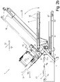
- FIGS. 1a , 1b show different perspective views of a multi-lane slicer 1 for the simultaneous slicing of several product calibers K on one lane SP1 to SP4 next to each other and depositing in shingled portions P each consisting of several slices S with a general direction of passage 10* through the slicer 1 from right to left .
- Figure 1c and Figure 2a show - without and with the caliber K inserted - a side view of this slicer 1, omitting covers and other parts that are not relevant to the invention and which, like all other units, are attached to the base frame 2, so that the functional parts, especially the conveyor belts, are better shown are recognizable.
- the longitudinal direction 10 is the feeding direction of the calibers K to the cutting unit 7 and thus also the longitudinal direction of the calibers K lying in the slicer 1.
- a slicer 1 the basic structure of a slicer 1 according to the prior art consists of a cutting unit 7 with several knives, in this case four, rotating about a knife axis 3′, such as a sickle knife 3, next to one another transversely to the feed direction 10
- Product caliber K lying on a feed conveyor 4 with spacers 15 of the feed conveyor 4 in between are fed by this feed unit 20, from the front ends of which the rotating knife 3 with its cutting edge 3a cuts off a slice S in one operation, i.e. almost simultaneously.
- the feed conveyor 4 is in the Figures 1a - 2a shown, in the side view at an angle, with a low-lying front end on the cutting side and a high-lying rear end, from which it can be folded down about a pivot axis 20' running in its width direction, the first transverse direction 11, which is located in the vicinity of the cutting unit 7 can be placed in an approximately horizontal loading position, as shown in Figure 2b is shown.
- each caliber K lying in the feed unit 20 is according to FIG Figure 2a each held by a gripper 14a - d in a form-fitting manner with the aid of gripper claws 16 .
- These grippers 14a-14d which can be activated and deactivated with regard to the position of the gripper claws 16, are attached to a common gripper carriage 13, which can be tracked along a gripper guide 18 in the feed direction 10.
- Both the feed of the gripper carriage 13 and the feed conveyor 4 can be driven in a controlled manner, although the specific feed speed of the calibers K is effected by a so-called upper and lower product guide 8, 9, which is also driven in a controlled manner and is located on the top and Attack the underside of the caliber K to be cut in the front end areas near the cutting unit 7:
- the front ends of the caliber K are each guided through a so-called spectacle opening 6a - d of a plate-shaped cutting spectacle 5, with the cutting plane 3" running directly in front of the front face of the cutting spectacle 5, which points downwards, and in which the knife 3 with its Cutting edge 3a rotates and thus separates the protruding caliber K from the cutting frame 5 as a disc S.
- the cutting plane 3" runs perpendicular to the upper run of the feed conveyor 4 and/or is spanned by the two transverse directions 11, 12 to the feed direction 10.
- the inner circumference of the spectacle openings 6a-d of the cutting edge 3a of the knife 3 serves as a shearbar.
- both product guides 8, 9 can be driven in a controlled manner, in particular independently of one another and/or possibly separately for each track SP1 to SP4, these determine the - continuous or clocked - feed rate of the calibers K through the cutting glasses 5.
- the upper product guide 8 is in the second transverse direction 12 - which is perpendicular to the surface of the upper run of the feed conveyor 4 - displaceable to adapt to the height H of the caliber K in this direction. Furthermore, at least one of the product guides 8, 9 can be designed to be pivotable about one of its deflection rollers in order to be able to change the direction of the strand of its guide belt resting on the caliber K to a limited extent.
- the slices S which stand at an angle in space during separation, fall onto a discharge unit 17 beginning below the cutting glasses 5 and running in the direction of passage 10*, which in this case consists of several discharge conveyors 17a, b, c, of which the first removal conveyor 17a in the throughput direction 10 can be designed as a portioning belt 17a and/or one can also be designed as a weighing unit.
- the slices S can hit the discharge unit 17 individually and at a distance from one another in the direction of passage 10*, or by appropriate control of the portioning belt 17a of the discharge unit 17 - the movement of which, like almost all moving parts, is controlled by the controller 1* - shingled or stacked Form portions P by stepwise forward movement of the portioning belt 17a.
- an approximately horizontally running residue conveyor 21 which begins with its front end below the cutting frame 5 and immediately below or behind the discharge unit 17 and with its upper strand there on it - by means of the drive of one of the discharge conveyors 17 against the flow direction 10 - falling residues are transported to the rear.
- Figure 3a shows a first embodiment of the drive and the guidance of the individual grippers 14.1 - 14.4 in the feed direction 10 in a plan view from above, i.e. perpendicular to the feed belt 4 of the feed unit 20:
- a carriage guide 18a, 18b in the form of a guide rod, for example.
- Two gripper slides are guided on each of the two slide guides 18a, b, namely on the slide guide 18a the two gripper slides 13.1, 13.2 arranged on this side of the longitudinal center 10', which are spaced apart in the feed direction 10 with their respective Guide part are guided on the guide 18a.
- the guide carriage 13.1 carries only one gripper 14.1, which is arranged on the track SP1 and holds the caliber K1 shown there as an example at its rear end, while the carriage 13.2 only carries the gripper 14.2, which can be moved along the track SP2 immediately next to it .
- Each of the gripper slides 13.1, 13.2 protrudes from the slide guide 18a only far enough in the direction of the longitudinal center 10' that it can carry the gripper 14.1 or 14.2 located on the corresponding track SP1 or SP2.
- a stationary carriage drive source 22a usually a carriage motor - for moving each of the gripper carriages 13.1, 13.2 assigned to this carriage guide 18a in the feed direction 10 and optionally a gripper activator 23a for activating and deactivating each gripper 14.1, 14.2 associated with this carriage guide 18a, if the gripper activation is not automatic when the caliber, for example K1, is contacted by the gripper, for example 14.1 takes place.
- a separate carriage drive source 22a for each carriage and a separate gripper activator 23a for each gripper for their independent operation.
- the corresponding drive sources for carriages and grippers can be arranged as far away as possible from the cutting unit 7 and, above all, stationary in order to be able to easily connect energy lines to these drive sources - not shown - at and To be able to supply signal lines that do not have to move along with the slides 13.1 to 13.4.
- each of the two gripper carriages 13.1, 13.2 guided on this carriage guide 18a can be driven independently of one another in the feed direction 10, apart from the fact that the two carriages running on this carriage guide 18a 13.1, 13.2 cannot overtake each other.
- the gripper carriage 13.1 is arranged with its guide part, with which it acts on the carriage guide 18a, in the direction of the cutting unit 7 in front of the carriage 13.2 on the carriage guide 18a, which is why the other carriage 13.2 on its gripper-side end has a support bracket pointing in the feed direction 10, at the front free end of which the gripper 14.2 is held, so that this gripper 14.2 can definitely also assume positions in the feed direction 10 before the gripper 14.1, whose gripper carriage 13.1 is guided on the same guide 18a.
- carriage guide 18a is not a guide rod encompassed by the guide parts of the carriages 13.1, 13.2, individual carriage guides, for example in the form of guide grooves, can be present on a guide beam on, for example, different sides of its circumference, on which one of the gripper slides 13.1, 13.2 can be guided, which can then also overtake each other.
- the carriage drive train connecting the carriage drive source 22a to the respective carriage can, for example, be formed integrally with the latter, for example in the form of a sliding shaft as a carriage guide 18a, or parallel to this, drive movements can be made along the carriage guide 18a into the respective gripper guided thereon -Carriage 13.1, 13.2, and also the gripper drive 23a in each of the two grippers 14.1, 14.2, in order to be able to operate them independently of one another, i.e. to be able to open and close them.
- one carriage here 13.2, as the master carriage, is set to its absolute target position relative to the stationary carriage drive source 22a by means of the carriage drive, while the other carriages 13.1, assigned to the same carriage guide 18a, are set as slave carriages only to a predetermined desired position relative to carriage 13.2 by means of an adjusting element 24a, which is preferably variable in length and is connected to the two carriages 13.1, 13.2 , controlled in turn by the carriage drive source 22a.
- the carriage drive train for the slave carriage thus preferably runs from the corresponding carriage drive source 22a along or by means of the carriage guide 18a and through or along the master carriage 13.2 to the slave carriage 13.1.
- both carriages 13.1, 13.2 are each guided with their guide part directly on the carriage guide 18a.
- grippers 14.3, 14.4 which are driven by the analog carriage drive source 22b and gripper activator 23b located there.
- Figure 3b shows a second solution according to the invention.
- the drive trains for the individual gripper carriage 13.1-13.4 are preferably as Figure 3a explained designed.
- the actuating element 24a, b can be controlled from the carriage drive source 22a via the respective master carriage 13.2, 13.3 in order to bring the gripper 14.1 or 14.4 into the desired desired position.
Applications Claiming Priority (1)
| Application Number | Priority Date | Filing Date | Title |
|---|---|---|---|
| DE102021101315.1A DE102021101315A1 (de) | 2021-01-22 | 2021-01-22 | Mehrspurige Aufschneide-Maschine mit unabhängig ansteuerbaren Greifern |
Publications (1)
| Publication Number | Publication Date |
|---|---|
| EP4032669A1 true EP4032669A1 (fr) | 2022-07-27 |
Family
ID=79927302
Family Applications (1)
| Application Number | Title | Priority Date | Filing Date |
|---|---|---|---|
| EP22152752.6A Pending EP4032669A1 (fr) | 2021-01-22 | 2022-01-21 | Machine à trancher à plusieurs pistes pourvue de pinces à commande indépendante |
Country Status (3)
| Country | Link |
|---|---|
| US (1) | US11945132B2 (fr) |
| EP (1) | EP4032669A1 (fr) |
| DE (1) | DE102021101315A1 (fr) |
Families Citing this family (1)
| Publication number | Priority date | Publication date | Assignee | Title |
|---|---|---|---|---|
| DE102020128533A1 (de) * | 2020-10-29 | 2022-05-05 | Weber Maschinenbau Gmbh Breidenbach | Aufschneidevorrichtung |
Citations (3)
| Publication number | Priority date | Publication date | Assignee | Title |
|---|---|---|---|---|
| DE19713163A1 (de) * | 1997-03-27 | 1998-10-15 | Biforce Anstalt | Vorrichtung zum Aufschneiden von Lebensmittelprodukten |
| DE102009039825A1 (de) * | 2009-09-02 | 2011-03-03 | Dipl.-Ing. Schindler & Wagner Kg | Schneidmaschine |
| DE102019123081A1 (de) * | 2019-08-28 | 2021-03-04 | Weber Maschinenbau Gmbh Breidenbach | Aufschneidevorrichtung und Verfahren zum Betreiben einer Aufschneidevorrichtung |
Family Cites Families (11)
| Publication number | Priority date | Publication date | Assignee | Title |
|---|---|---|---|---|
| JP4377572B2 (ja) | 2002-09-12 | 2009-12-02 | 菱和株式会社 | 食品原木スライス装置 |
| US20070214969A1 (en) * | 2003-10-15 | 2007-09-20 | Peter Mueller | Method and Device for Slicing Food Bars |
| JP4768643B2 (ja) | 2007-01-17 | 2011-09-07 | アサヒ技研株式会社 | ハム原木等のスライス装置 |
| EP2566670B1 (fr) | 2010-05-01 | 2016-07-06 | Formax, Inc. | Machine à trancher à grande vitesse |
| EP2420362B1 (fr) * | 2010-08-18 | 2015-04-15 | Weber Maschinenbau GmbH Breidenbach | Procédé et dispositif destinés à la coupe de produits alimentaires |
| DE102011111601A1 (de) * | 2011-07-08 | 2013-01-10 | Weber Maschinenbau Gmbh Breidenbach | Vorrichtung zum Aufschneiden von Lebensmittelprodukten |
| DE102014112800A1 (de) * | 2014-09-05 | 2016-03-10 | Weber Maschinenbau Gmbh Breidenbach | Aufschneidevorrichtung |
| DE102015107716A1 (de) * | 2015-05-18 | 2016-11-24 | Weber Maschinenbau Gmbh Breidenbach | Zuführvorrichtung |
| DE102015110534A1 (de) * | 2015-06-30 | 2017-01-05 | Weber Maschinenbau Gmbh Breidenbach | Zuführvorrichtung |
| DE102016112085A1 (de) | 2016-07-01 | 2018-01-04 | Weber Maschinenbau Gmbh Breidenbach | Vorrichtung zum aufschneiden von lebensmittelprodukten |
| DE102016120982A1 (de) * | 2016-11-03 | 2018-05-03 | Weber Maschinenbau Gmbh Breidenbach | Vorrichtung und Verfahren zum Aufschneiden von Produkten |
-
2021
- 2021-01-22 DE DE102021101315.1A patent/DE102021101315A1/de active Pending
-
2022
- 2022-01-21 EP EP22152752.6A patent/EP4032669A1/fr active Pending
- 2022-01-21 US US17/581,295 patent/US11945132B2/en active Active
Patent Citations (3)
| Publication number | Priority date | Publication date | Assignee | Title |
|---|---|---|---|---|
| DE19713163A1 (de) * | 1997-03-27 | 1998-10-15 | Biforce Anstalt | Vorrichtung zum Aufschneiden von Lebensmittelprodukten |
| DE102009039825A1 (de) * | 2009-09-02 | 2011-03-03 | Dipl.-Ing. Schindler & Wagner Kg | Schneidmaschine |
| DE102019123081A1 (de) * | 2019-08-28 | 2021-03-04 | Weber Maschinenbau Gmbh Breidenbach | Aufschneidevorrichtung und Verfahren zum Betreiben einer Aufschneidevorrichtung |
Also Published As
| Publication number | Publication date |
|---|---|
| US20220234236A1 (en) | 2022-07-28 |
| US11945132B2 (en) | 2024-04-02 |
| DE102021101315A1 (de) | 2022-07-28 |
Similar Documents
| Publication | Publication Date | Title |
|---|---|---|
| EP2468466B1 (fr) | Dispositif et procédé destinés à la coupe de plusieurs produits alimentaires | |
| EP2420362B1 (fr) | Procédé et dispositif destinés à la coupe de produits alimentaires | |
| EP2671829B1 (fr) | Dispositif d'écartement | |
| EP2420364B1 (fr) | Equipement destiné à compléter une portion lors de la coupe sur plusieurs voies | |
| EP3170632B1 (fr) | Dispositif et procédé destinés au découpage de produits alimentaires | |
| EP3416786B1 (fr) | Dispositif de préhension | |
| EP4032669A1 (fr) | Machine à trancher à plusieurs pistes pourvue de pinces à commande indépendante | |
| EP0634325B1 (fr) | Dispositif pour arranger des articles coupés en les répartissant comme des bardeaux | |
| EP0867263A2 (fr) | Système d'alimentation de produits dans une machine à débiter en tranches | |
| EP3277605B1 (fr) | Convoyeur à bande à auges pour transporter des poissons de manière transversale par rapport à leur extension longitudinale dans une direction de transport, ensemble et procédé | |
| DE102019123081A1 (de) | Aufschneidevorrichtung und Verfahren zum Betreiben einer Aufschneidevorrichtung | |
| EP3409125B1 (fr) | Dispositif d'extraction des arêtes latérales à partir de filets de poisson, machine de filetage avec un tel dispositif et procédé d'extraction des arêtes latérales à partir de filets de poisson | |
| EP4001187A1 (fr) | Procédé de positionnement transversal d'un article à transporter | |
| EP3380419B1 (fr) | Procédé et dispositif de mise en portions de tranches d'un produit alimentaire avec modification de forme, notamment pliage, de la portion | |
| EP4000829A1 (fr) | Procédé de positionnement d'un article à transporter, ainsi que dispositif de mise en uvre du procédé | |
| DE102006015346A1 (de) | Vorrichtung zum Schneiden von Lebensmittelprodukten | |
| DE102020133162A1 (de) | Aufschneide-Maschine | |
| EP0816028B1 (fr) | Dispositif ainsi que méthode pour le travail d'un matériau stratifié | |
| EP0133305A1 (fr) | Dispositif d'alimentation de produits en forme de barres | |
| EP0899197A2 (fr) | Procédé et dispositif de répartition d'un flot de produits | |
| EP3593965B1 (fr) | Dispositif de découpage en tranches de produits alimentaires | |
| DE10026759A1 (de) | Schneidmaschine zum Schneiden von Lebensmittelprodukten | |
| EP0956929B2 (fr) | Dispositif pour la coupe d'un produit en morceaux cunéiformes | |
| EP2848379B1 (fr) | Dispositif de coupe | |
| DE102021100897A1 (de) | Aufschneide-Maschine |
Legal Events
| Date | Code | Title | Description |
|---|---|---|---|
| PUAI | Public reference made under article 153(3) epc to a published international application that has entered the european phase |
Free format text: ORIGINAL CODE: 0009012 |
|
| STAA | Information on the status of an ep patent application or granted ep patent |
Free format text: STATUS: THE APPLICATION HAS BEEN PUBLISHED |
|
| AK | Designated contracting states |
Kind code of ref document: A1 Designated state(s): AL AT BE BG CH CY CZ DE DK EE ES FI FR GB GR HR HU IE IS IT LI LT LU LV MC MK MT NL NO PL PT RO RS SE SI SK SM TR |
|
| STAA | Information on the status of an ep patent application or granted ep patent |
Free format text: STATUS: REQUEST FOR EXAMINATION WAS MADE |
|
| 17P | Request for examination filed |
Effective date: 20230120 |
|
| RBV | Designated contracting states (corrected) |
Designated state(s): AL AT BE BG CH CY CZ DE DK EE ES FI FR GB GR HR HU IE IS IT LI LT LU LV MC MK MT NL NO PL PT RO RS SE SI SK SM TR |
|
| P01 | Opt-out of the competence of the unified patent court (upc) registered |
Effective date: 20230519 |