EP0952412B1 - Refrigerating system and method of operating the same - Google Patents
Refrigerating system and method of operating the same Download PDFInfo
- Publication number
- EP0952412B1 EP0952412B1 EP99106297A EP99106297A EP0952412B1 EP 0952412 B1 EP0952412 B1 EP 0952412B1 EP 99106297 A EP99106297 A EP 99106297A EP 99106297 A EP99106297 A EP 99106297A EP 0952412 B1 EP0952412 B1 EP 0952412B1
- Authority
- EP
- European Patent Office
- Prior art keywords
- pressure
- refrigerant
- compressor
- refrigerating system
- lower evaporating
- Prior art date
- Legal status (The legal status is an assumption and is not a legal conclusion. Google has not performed a legal analysis and makes no representation as to the accuracy of the status listed.)
- Expired - Lifetime
Links
Images
Classifications
-
- F—MECHANICAL ENGINEERING; LIGHTING; HEATING; WEAPONS; BLASTING
- F25—REFRIGERATION OR COOLING; COMBINED HEATING AND REFRIGERATION SYSTEMS; HEAT PUMP SYSTEMS; MANUFACTURE OR STORAGE OF ICE; LIQUEFACTION SOLIDIFICATION OF GASES
- F25B—REFRIGERATION MACHINES, PLANTS OR SYSTEMS; COMBINED HEATING AND REFRIGERATION SYSTEMS; HEAT PUMP SYSTEMS
- F25B49/00—Arrangement or mounting of control or safety devices
- F25B49/02—Arrangement or mounting of control or safety devices for compression type machines, plants or systems
- F25B49/022—Compressor control arrangements
-
- F—MECHANICAL ENGINEERING; LIGHTING; HEATING; WEAPONS; BLASTING
- F04—POSITIVE - DISPLACEMENT MACHINES FOR LIQUIDS; PUMPS FOR LIQUIDS OR ELASTIC FLUIDS
- F04B—POSITIVE-DISPLACEMENT MACHINES FOR LIQUIDS; PUMPS
- F04B27/00—Multi-cylinder pumps specially adapted for elastic fluids and characterised by number or arrangement of cylinders
- F04B27/08—Multi-cylinder pumps specially adapted for elastic fluids and characterised by number or arrangement of cylinders having cylinders coaxial with, or parallel or inclined to, main shaft axis
- F04B27/14—Control
- F04B27/16—Control of pumps with stationary cylinders
- F04B27/18—Control of pumps with stationary cylinders by varying the relative positions of a swash plate and a cylinder block
- F04B27/1804—Controlled by crankcase pressure
-
- F—MECHANICAL ENGINEERING; LIGHTING; HEATING; WEAPONS; BLASTING
- F25—REFRIGERATION OR COOLING; COMBINED HEATING AND REFRIGERATION SYSTEMS; HEAT PUMP SYSTEMS; MANUFACTURE OR STORAGE OF ICE; LIQUEFACTION SOLIDIFICATION OF GASES
- F25B—REFRIGERATION MACHINES, PLANTS OR SYSTEMS; COMBINED HEATING AND REFRIGERATION SYSTEMS; HEAT PUMP SYSTEMS
- F25B41/00—Fluid-circulation arrangements
- F25B41/20—Disposition of valves, e.g. of on-off valves or flow control valves
- F25B41/22—Disposition of valves, e.g. of on-off valves or flow control valves between evaporator and compressor
-
- F—MECHANICAL ENGINEERING; LIGHTING; HEATING; WEAPONS; BLASTING
- F25—REFRIGERATION OR COOLING; COMBINED HEATING AND REFRIGERATION SYSTEMS; HEAT PUMP SYSTEMS; MANUFACTURE OR STORAGE OF ICE; LIQUEFACTION SOLIDIFICATION OF GASES
- F25B—REFRIGERATION MACHINES, PLANTS OR SYSTEMS; COMBINED HEATING AND REFRIGERATION SYSTEMS; HEAT PUMP SYSTEMS
- F25B9/00—Compression machines, plants or systems, in which the refrigerant is air or other gas of low boiling point
- F25B9/002—Compression machines, plants or systems, in which the refrigerant is air or other gas of low boiling point characterised by the refrigerant
- F25B9/008—Compression machines, plants or systems, in which the refrigerant is air or other gas of low boiling point characterised by the refrigerant the refrigerant being carbon dioxide
-
- F—MECHANICAL ENGINEERING; LIGHTING; HEATING; WEAPONS; BLASTING
- F04—POSITIVE - DISPLACEMENT MACHINES FOR LIQUIDS; PUMPS FOR LIQUIDS OR ELASTIC FLUIDS
- F04B—POSITIVE-DISPLACEMENT MACHINES FOR LIQUIDS; PUMPS
- F04B27/00—Multi-cylinder pumps specially adapted for elastic fluids and characterised by number or arrangement of cylinders
- F04B27/08—Multi-cylinder pumps specially adapted for elastic fluids and characterised by number or arrangement of cylinders having cylinders coaxial with, or parallel or inclined to, main shaft axis
- F04B27/14—Control
- F04B27/16—Control of pumps with stationary cylinders
- F04B27/18—Control of pumps with stationary cylinders by varying the relative positions of a swash plate and a cylinder block
- F04B27/1804—Controlled by crankcase pressure
- F04B2027/1809—Controlled pressure
- F04B2027/1813—Crankcase pressure
-
- F—MECHANICAL ENGINEERING; LIGHTING; HEATING; WEAPONS; BLASTING
- F04—POSITIVE - DISPLACEMENT MACHINES FOR LIQUIDS; PUMPS FOR LIQUIDS OR ELASTIC FLUIDS
- F04B—POSITIVE-DISPLACEMENT MACHINES FOR LIQUIDS; PUMPS
- F04B27/00—Multi-cylinder pumps specially adapted for elastic fluids and characterised by number or arrangement of cylinders
- F04B27/08—Multi-cylinder pumps specially adapted for elastic fluids and characterised by number or arrangement of cylinders having cylinders coaxial with, or parallel or inclined to, main shaft axis
- F04B27/14—Control
- F04B27/16—Control of pumps with stationary cylinders
- F04B27/18—Control of pumps with stationary cylinders by varying the relative positions of a swash plate and a cylinder block
- F04B27/1804—Controlled by crankcase pressure
- F04B2027/1822—Valve-controlled fluid connection
- F04B2027/1827—Valve-controlled fluid connection between crankcase and discharge chamber
-
- F—MECHANICAL ENGINEERING; LIGHTING; HEATING; WEAPONS; BLASTING
- F04—POSITIVE - DISPLACEMENT MACHINES FOR LIQUIDS; PUMPS FOR LIQUIDS OR ELASTIC FLUIDS
- F04B—POSITIVE-DISPLACEMENT MACHINES FOR LIQUIDS; PUMPS
- F04B27/00—Multi-cylinder pumps specially adapted for elastic fluids and characterised by number or arrangement of cylinders
- F04B27/08—Multi-cylinder pumps specially adapted for elastic fluids and characterised by number or arrangement of cylinders having cylinders coaxial with, or parallel or inclined to, main shaft axis
- F04B27/14—Control
- F04B27/16—Control of pumps with stationary cylinders
- F04B27/18—Control of pumps with stationary cylinders by varying the relative positions of a swash plate and a cylinder block
- F04B27/1804—Controlled by crankcase pressure
- F04B2027/184—Valve controlling parameter
- F04B2027/1854—External parameters
-
- F—MECHANICAL ENGINEERING; LIGHTING; HEATING; WEAPONS; BLASTING
- F04—POSITIVE - DISPLACEMENT MACHINES FOR LIQUIDS; PUMPS FOR LIQUIDS OR ELASTIC FLUIDS
- F04B—POSITIVE-DISPLACEMENT MACHINES FOR LIQUIDS; PUMPS
- F04B27/00—Multi-cylinder pumps specially adapted for elastic fluids and characterised by number or arrangement of cylinders
- F04B27/08—Multi-cylinder pumps specially adapted for elastic fluids and characterised by number or arrangement of cylinders having cylinders coaxial with, or parallel or inclined to, main shaft axis
- F04B27/14—Control
- F04B27/16—Control of pumps with stationary cylinders
- F04B27/18—Control of pumps with stationary cylinders by varying the relative positions of a swash plate and a cylinder block
- F04B27/1804—Controlled by crankcase pressure
- F04B2027/1886—Open (not controlling) fluid passage
- F04B2027/1895—Open (not controlling) fluid passage between crankcase and suction chamber
-
- F—MECHANICAL ENGINEERING; LIGHTING; HEATING; WEAPONS; BLASTING
- F25—REFRIGERATION OR COOLING; COMBINED HEATING AND REFRIGERATION SYSTEMS; HEAT PUMP SYSTEMS; MANUFACTURE OR STORAGE OF ICE; LIQUEFACTION SOLIDIFICATION OF GASES
- F25B—REFRIGERATION MACHINES, PLANTS OR SYSTEMS; COMBINED HEATING AND REFRIGERATION SYSTEMS; HEAT PUMP SYSTEMS
- F25B2309/00—Gas cycle refrigeration machines
- F25B2309/06—Compression machines, plants or systems characterised by the refrigerant being carbon dioxide
- F25B2309/061—Compression machines, plants or systems characterised by the refrigerant being carbon dioxide with cycle highest pressure above the supercritical pressure
-
- F—MECHANICAL ENGINEERING; LIGHTING; HEATING; WEAPONS; BLASTING
- F25—REFRIGERATION OR COOLING; COMBINED HEATING AND REFRIGERATION SYSTEMS; HEAT PUMP SYSTEMS; MANUFACTURE OR STORAGE OF ICE; LIQUEFACTION SOLIDIFICATION OF GASES
- F25B—REFRIGERATION MACHINES, PLANTS OR SYSTEMS; COMBINED HEATING AND REFRIGERATION SYSTEMS; HEAT PUMP SYSTEMS
- F25B2341/00—Details of ejectors not being used as compression device; Details of flow restrictors or expansion valves
- F25B2341/06—Details of flow restrictors or expansion valves
- F25B2341/063—Feed forward expansion valves
-
- F—MECHANICAL ENGINEERING; LIGHTING; HEATING; WEAPONS; BLASTING
- F25—REFRIGERATION OR COOLING; COMBINED HEATING AND REFRIGERATION SYSTEMS; HEAT PUMP SYSTEMS; MANUFACTURE OR STORAGE OF ICE; LIQUEFACTION SOLIDIFICATION OF GASES
- F25B—REFRIGERATION MACHINES, PLANTS OR SYSTEMS; COMBINED HEATING AND REFRIGERATION SYSTEMS; HEAT PUMP SYSTEMS
- F25B2600/00—Control issues
- F25B2600/17—Control issues by controlling the pressure of the condenser
Definitions
- the present invention generally relates to a method of operating a refrigerating system. More particularly, the present invention relates to a method of operating a refrigerating system wherein at least a compressor, a heat-dissipation type heat exchanger, a throttling means and a heat-absorption type heat exchanger are connected in series to form a closed circuit, which includes a first refrigerant circuit section having a higher pressure and a second refrigerant circuit section having a lower evaporating pressure, so that the higher pressure in the closed circuit becomes the supercritical pressure of the refrigerant circulating in the closed circuit.
- the method of operating a refrigerating system according to the present invention can be suitably used in an air-conditioner for an automobile.
- JP 10 089785 A discloses a method of operating a refrigerating system which includes at least a compressor, a heat-dissipation type heat exchanger, throttling means and a heat-absorption type heat exchanger which are connected in series with each other to form a closed circuit for circulating a refrigerant, said closed circuit including a first refrigerant circuit section having a higher pressure and a second refrigerant circuit section having a lower evaporating pressure, wherein the method comprises the steps of: operating said refrigerating system so that the higher pressure in said closed circuit becomes the supercritical pressure of said refrigerant circulating in said closed circuit; and controlling said refrigerating system so that the lower evaporating pressure increases as the higher pressure increases.
- the refrigerating system disclosed in Japanese Unexamined Patent Publication (Kohyo) No. 6-510111 on the basis of PCT/No91/00119 includes a compressor, a heat-dissipation type heat exchanger (gas cooler), a throttling means, a heat-absorption type heat exchanger (evaporator) and a vapor-liquid separator (accumulator), which are connected in series with each other to form a closed circuit, the refrigerating system being operated so that the higher pressure in the closed circuit becomes the supercritical pressure of the refrigerant circulating in the closed circuit.
- the higher pressure is adjusted by detecting at least one operating condition such as the exit temperature of the gas cooler disposed on the higher pressure side as a heat-dissipation type heat exchanger and controlling the throttling means disposed downstream from the gas cooler in accordance with the detected operation condition(s), to minimize an energy consumption in the refrigerating system.
- at least one operating condition such as the exit temperature of the gas cooler disposed on the higher pressure side as a heat-dissipation type heat exchanger
- COP Q/W
- the value of COP is determined from both the refrigerating performance (Q) and the compression work (W).
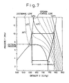
- a supercritical cycle refrigerating system In a refrigerating system operated under conditions where the higher pressure in the closed circuit constituting the refrigerating system becomes the supercritical pressure of refrigerant (such an system may properly be referred to as "a supercritical cycle refrigerating system” hereinafter), it is possible to increase the above-mentioned value of COP by increasing the higher pressure in the closed circuit constituting the refrigerating system and thereby increasing the above-mentioned refrigerating performance (Q), provided the refrigerant is maintained generally at a constant temperature at the exit of the gas cooler.
- a pressure-enthalpy diagram of Fig. 7 which is a P-H diagram or Mollier diagram in a supercritical cycle using carbon dioxide (CO 2 ) as a refrigerant
- the enthalpy (H c ) at the exit of the gas cooler (point C) is reduced as the higher pressure increases, as is apparent from an isothermal curve for 40°C shown in the P-H diagram of Fig. 7.
- the refrigerant temperature and pressure are detected at the exit of the gas cooler (point C), and the optimum value of the higher pressure at the detected temperature is determined based on the above-mentioned optimum control curve. Thereafter, the throttling means is controlled in accordance with an actual higher pressure so that the actual pressure becomes the optimum pressure thus determined, whereby the COP value is maximized and the energy consumption in the refrigerating system is minimized.
- variable displacement type compressor capable of varying a discharge capacity by detecting a suction pressure (a refrigerant pressure at the exit of the evaporator) or a refrigerant temperature at the exit of the evaporator, so that the discharge capacity of the compressor becomes smaller when the engine rotational speed increases, it must be expected that the refrigerant temperature increases in the evaporator due to the decrease in the refrigerant circulation rate and the increase in the suction pressure (i.e., the increase in the refrigerant pressure in the evaporator) due to the reduction in the discharge capacity, which can effectively prevent excessive refrigeration from occurring when the rotational speed increases.
- the above-mentioned supercritical cycle refrigerating system has several problems. For example, when the discharge capacity of the compressor is modulated with the same control characteristic as that of the refrigerating system of subcritical cycle, it is difficult to quickly carry out the capacity control of the compressor when the engine rotational speed increases, because the action of the throttling means is different in the supercritical cycle from that in the subcritical cycle.
- the refrigerant temperature is detected at the exit of the evaporator, and the optimum pressure corresponding to this detected temperature is compared with the actual refrigerant pressure at the exit of the evaporator to control the throttling means so that the actual refrigerant pressure at the exit of the evaporator becomes optimum.
- the optimum pressure at the exit of the evaporator means a pressure under which the degree of superheating of the refrigerant is constant at the exit of the evaporator.
- the circulation rate of the refrigerant through the evaporator is adjusted by controlling the opening degree of the throttling means so that the actual refrigerant pressure at the exit of the evaporator becomes the optimum pressure.
- the throttling means operates in such a manner, the refrigerant is not completely vaporized in the evaporator due to the increase in the circulation rate of the refrigerant supplied to the evaporator from the compressor, and the refrigerant temperature is lowered at the exit of the evaporator in correspondence to the degree of superheating. If the refrigerant temperature is lowered at the exit of the evaporator, the optimum pressure is also lowered in accordance with the refrigerant temperature.
- the opening degree of the throttling means is reduced in order to lower the actual refrigerant pressure, at the exit of the evaporator, to the above-mentioned optimum pressure. Since the resistance against the refrigerant flow increases due to the throttling action of the throttling means, the circulation rate of the refrigerant through the evaporator is reduced. Also, since the refrigerant pressure in the evaporator is lowered, in accordance with the reduction in the circulation rate of the refrigerant, to lower the suction pressure of the compressor, the volumetric efficiency of the compressor deteriorates.
- the refrigerating performance is lowered to prevent excessive refrigeration.
- the suction pressure of the compressor and the refrigerant temperature at the exit of the evaporator are quickly lowered due to the throttling action of the throttling means, it is possible, by detecting such values, to quickly carry out the volumetric control of the compressor, which also prevents excessive refrigeration.
- the throttling means quickly acts in the throttling direction, even if the rotational speed excessively increases, excessive refrigeration is assuredly prevented by reducing the circulation rate of the refrigerant and other measures. Also, since the throttling means acts in the throttling direction to quickly lower the suction pressure of the compressor, it is possible to quickly and assuredly carry out the volumetric control of the compressor by detecting such a suction pressure and other measures and, as a result, to prevent excessive refrigeration from occurring.
- the maximization of COP and therefore the minimization of the energy consumption in the refrigerating system is achieved by adjusting the opening degree of the throttling means based on the detected refrigerant temperature and pressure at the exit of the gas cooler (point C), as stated above, so that the actual refrigerant pressure at the exit of the gas cooler (point C) becomes the optimum pressure at the detected temperature.
- a mass flow rate of the refrigerant supplied to the gas cooler also increases, whereby a refrigerant pressure in the gas cooler (a higher pressure; a discharge pressure) becomes also higher.
- the opening degree of the throttling means is adjusted so that the refrigerant pressure at the exit of the gas cooler is maintained at a constant value as stated above, the opening degree of the throttling means is made large to suppress the increase of the refrigerant pressure at the exit of the gas cooler.
- a method of operating a refrigerating system which includes at least a compressor, a heat-dissipation type heat exchanger, throttling means and a heat-absorption type heat exchanger which are connected in series with each other to form a closed circuit for circulating a refrigerant, the closed circuit including a first refrigerant circuit section having a higher pressure and a second refrigerant circuit section having a lower evaporating pressure
- the method comprising the steps of: operating the refrigerating system so that the higher pressure in the closed circuit becomes the supercritical pressure of the refrigerant circulating in the closed circuit; and controlling the refrigerating system so that the lower evaporating pressure increases as the higher pressure increases; wherein a variable displacement type compressor capable of varying a discharge capacity is used as said compressor and the discharge capacity of said variable displacement type compressor is reduced as the higher pressure in said first circuit section increases.
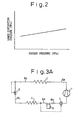
- This operating method is based on a control characteristic property represented by an upwardly slanted straight line or curve of a predetermined inclination angle in coordinates defined by x axis representing the higher pressure and y axis representing the lower evaporating pressure.
- the refrigerant circulation rate is controlled in a variable manner while using the lower evaporating pressure as a preset pressure, or more concretely when the control is carried out in such a manner that if the evaporating temperature becomes lower than a first preset temperature, t 1 , the electromagnetic clutch of the compressor is turned off, and if the evaporating temperature becomes higher than a second preset value t 2 (> t 1 ), the electromagnetic clutch of the compressor is turned on, the control characteristic property being such that the preset temperature t 1 becomes higher as the higher pressure increases).
- the discharge capacity of the compressor is variably controlled or the opening degree of a suction throttle valve provided at a position upstream from the compressor may be variably controlled.
- a variable displacement type compressor capable of varying a discharge capacity is used as the compressor.
- the discharge capacity of the compressor is variable while using the lower evaporating pressure as a preset pressure. That is, when the lower evaporating pressure becomes lower than the preset pressure, the discharge capacity of the compressor is reduced, which results in the reduction in the circulation rate of the refrigerant through the evaporator and thus in the reduction of the refrigerating performance.
- the method of operating a refrigerating system is conducted, wherein the discharge capacity of the variable displacement type compressor is reduced as the higher pressure in the first circuit section increases.
- variable displacement type compressor is capable of increasing the interior pressure in the crank chamber thereof as the higher pressure increases and capable of reducing the discharge rate based on the increase in the interior pressure in the crank chamber. Accordingly, as the higher pressure increases, the interior pressure in the crank chamber also is increased to reduce the discharge capacity of the compressor, whereby the lower evaporating pressure increases based thereon.
- the method of operating a refrigerating system may further comprise the steps of: detecting a refrigerant pressure prior to compression as the lower evaporating pressure and a refrigerant pressure after compression as the higher pressure, respectively; predetermining a control characteristic property so that a target value for the lower evaporating pressure in the closed circuit increases as the higher pressure in the closed circuit increases; determining the target value for the lower evaporating pressure corresponding to the detected higher pressure based on the predetermined control characteristic property; and reducing the discharge rate from the compressor so that the lower evaporating pressure coincides with the target value, when the detected lower evaporating pressure is lower than the determined target value for the lower evaporating pressure.
- the lower evaporating pressure and the higher pressure are detected. Based on the control characteristic property predetermined so that the lower evaporating pressure increases as the higher pressure increases, the target value for the lower evaporating pressure is determined in correspondence with the detected higher pressure. If the actual detected value of the lower evaporating pressure is lower than the target value, the discharge capacity of the compressor is made to reduce so that the lower evaporating pressure coincides with the target value. Therefore, it is possible to carry out the operation of the refrigerating system having the control characteristic property wherein the lower evaporating pressure becomes higher as the higher pressure increases.
- control characteristic property represents an upwardly inclined generally straight line shown in coordinates defined by an ordinate representing the lower evaporating pressure and an obscissa representing the higher pressure.
- the lower evaporating pressure of the refrigerant is a detected pressure of the refrigerant prior to being taken into the compressor, while the higher pressure of the refrigerant is a detected pressure of the refrigerant discharged from the compressor.
- the method of operating a refrigerating system is provided, wherein the refrigerant is carbon dioxide.
- the refrigerant is carbon dioxide.
- ethylene (C 2 H 4 ), diborane (B 2 H 6 ), ethane (C 2 H 6 ), nitrogen oxide or others may be employed as the refrigerant, besides carbon dioxide (CO 2 ).
- a refrigerating system for operating the method according to the invention includes at least a compressor, a heat-dissipation type heat exchanger, throttling means and a heat-absorption type heat exchanger which are connected in series with each other to form a closed circuit for circulating a refrigerant, the closed circuit including a first refrigerant circuit section having a higher pressure and a second refrigerant circuit section having a lower evaporating pressure, wherein the refrigerating system is adapted so that the higher pressure of the closed circuit becomes the supercritical pressure of the refrigerant circulating in the closed circuit, and further includes a control means operative to increase the lower evaporating pressure of the second circuit section in accordance with a predetermined control characteristic property when the higher pressure of the first circuit section increases.
- the compressor of the refrigerating system is a variable displacement type compressor adapted so that the discharge capacity of the variable displacement type compressor is adjustably controlled by the control means.
- variable displacement type compressor of the refrigerating system is controlled by the control means so that the discharge capacity thereof is reduced as the higher pressure of the first circuit section increases.
- the compressor of the refrigerating system further includes a first sensor for detecting a pressure of the refrigerant prior to being compressed by the compressor; and a second sensor for detecting a pressure of the refrigerant after being compressed; and the control means determines a target value for the lower evaporating pressure in correspondence to the higher pressure detected by the second sensor, based on the predetermined control characteristic property defined to increase the target value for the lower evaporating pressure detected by the first sensor as the higher pressure detected by the second sensor increases, and reduces the discharge capacity of the compreesor so that the lower evaporating pressure coincides with the target value when the value of the lower evaporating pressure is detected by the first sensor lower than the target value.
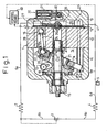
- a refrigerating system shown in Fig. 1 is used for an air-conditioner for an automobile, and includes a closed circuit including a compressor 1, a gas cooler 2 used as a heat-dissipation type heat exchanger, an expansion valve 3 used as a throttling means, an evaporator 4 used as a heat-absorption type heat exchanger and an accumulator 5 used as a vapor-liquid separator, which are connected in series with each other.
- a discharge chamber 26 of the compressor 1 is connected via a pipe 6a to the gas cooler 2 which is connected via a pipe 6b to the expansion valve 3 which in turn is connected via a pipe 6c to the evaporator 4 which is then connected via a pipe 6d to the accumulator 5 which is again connected via a pipe 6e to a suction chamber 27 of the compressor 1, so that a closed refrigerant circuit is completed.
- the closed circuit includes a first refrigerant circuit section having a higher pressure and a second refrigerant circuit section having a lower evaporating pressure.
- This refrigerating system operates so that the higher pressure in the refrigeration circuit becomes the supercritical pressure of a refrigerant circulating in the circuit.
- Carbon dioxide (CO 2 ) is used as a refrigerant.
- the opening degree of the expansion valve 3 is controlled based on the detected temperature and pressure of the refrigerant at the exit of the gas cooler 2 so that the relationship between the refrigerant temperature and pressure corresponds to the above-mentioned optimum control curve; i.e., the COP value becomes a maximum.
- the compressor 1 is of a variable displacement type capable of varying its discharge flow rate, wherein the discharge rate is reduced in accordance with the increase in the interior pressure of a crank chamber 14 of the compressor 1, while the pressure in the crank chamber 14 becomes higher as the higher pressure increases.
- a front housing 11 is coupled to a front end of a cylinder block 10, and a rear housing 13 is coupled via a valve plate 12 or others to a rear end of the cylinder block 10.
- a driving shaft 15 one end of which extends from the front housing 11 and is secured to an armature of an electromagnetic clutch not shown.
- the driving shaft 15 is supported for rotation by a sealing device and a radial bearing provided between the front housing 11 and the cylinder block 10.
- a thrust bearing and a leaf spring not shown are interposed between the other end of the driving shaft 15 and the valve plate 12 or others.
- a plurality of bores 10a are provided in the cylinder block 10 at positions encircling the driving shaft 15, and accommodate therein pistons 16, respectively.
- a rotor 18 is fixed to the driving shaft 15 via a thrust bearing at a distance from the front housing 11 to be rotatable in synchronism with the driving shaft 15, and a rotary swash plate 20 is pivoted behind the rotor 18 via a hinge mechanism 19 to be rotatable in synchronism with the rotor 18.
- a sleeve 21 is slidably fitted onto the circumference of the driving shaft 15 in the crank chamber 14, and the rotary swash plate 20 is rockably pivoted on a pin 21a projected from the sleeve 21.
- a rocking swash plate 23 On the rotary swash plate 20 is held, via a thrust bearing 22 or the like, a rocking swash plate 23, to which an anti-rotation pin, not shown, movable solely in the axial direction in an anti-rotation groove 11a of the front housing, is fixed.
- a rod 24 is provided between the rocking swash plate 23 and the respective piston 16 to be held thereby, so that the respective piston is reciprocated within the respective bore 10a in accordance with inclination angles of the rocking swash plate 23.
- a compressive spring 25 is provided between the sleeve 21 and a circlip fixed onto the driving shaft 15 on the side of the cylinder block 10.
- the rotary swash plate 20 is capable of abutting to the rotor 18, whereby the rocking swash plate 23 is maintained at the maximum angle at the starting point.
- the compressive spring 25 is compressed to the maximum extent, the rocking swash plate 23 is kept at the minimum inclination angle.
- the discharge chamber 26 is formed in a central region, and the suction chamber 27 is formed outside the discharge chamber 26.
- Each of compression chambers defined by an end surface of the respective piston 16 and the respective bore 10a communicates with the discharge chamber 26 through each of discharge ports formed in the valve plate 12.
- the respective discharge port is openable and closable by the action of a discharge valve, the opening degree of which is controllable on the side of discharge chamber 26 by a retainer 26a.
- the respective compression chamber communicates with the suction chamber 27 through each of suction ports formed in the valve plate 12, wherein the respective suction port is openable and closable on the side of the respective compression chamber by the action of a suction valve.
- An air-extraction path 28 for communicating the crank chamber 14 with the suction chamber 27 is provided in the rear housing 13, the valve plate 12, the cylinder block 10 or others. Also, an air-feeding path 29 is formed as a control path for communicating the discharge chamber 26 with the crank chamber 14. In this regard, a volumetric control valve 30 is provided in the rear housing 13 at a position midway of the air-feeding path 29.
- a ball-like valve body 32 is displaceable upward/downward by the action of a solenoid 31 to adjust the opening degree of the air-feeding path 29.
- the solenoid 31 controllable by a control means 40.
- a value of a lower evaporating pressure detected by a pressure sensor 41 provided in the pipe 6e upstream from the compressor 1 and a value of a higher pressure detected by a pressure sensor 42 provided in the pipe 6a downstream from the compressor 1 are input to the control means 40.
- a control characteristic property defined so that, as the higher pressure increases, the lower evaporating pressure becomes higher is preliminarily stored in the control means 40 (such a control characteristic property is shown as a straight line in Fig.
- the rotation of an engine is transmitted as a driving source to the driving shaft 15 of the compressor 1 via an electromagnetic clutch.
- the rotary swash plate 20 is made to rotate at a predetermined inclination angle in synchronism with the rotor 18 by the rotation of the driving shaft 15, wherein solely a rocking motion of the rotary swash plate 20 is transmitted to the rocking swash plate 23.
- the piston 16 reciprocates within the cylinder 10a via the rod 24 due to the rocking motion of the rocking swash plate 23.
- the refrigerant in the suction chamber 27 is compressed in the compression chamber, and then discharged into the discharge chamber 26.
- the refrigerant discharged into the discharge chamber 26 is supplied to the gas cooler 2 via the pipe 6a.
- the refrigerant at a high temperature and at a high pressure is cooled by the gas cooler 2 to a temperature approximately equal to that of environmental air, and the cooled refrigerant is supplied to the expansion valve 3 via the pipe 6b.
- the refrigerant supplied to the expansion valve 3 is decompressed by the above-mentioned control, based on the refrigerant temperature and pressure, at the exit of the gas cooler 2 and is converted into a mist of low temperature and low pressure (in a vapor-liquid phase).
- the refrigerant thus converted into the mist phase is supplied to the evaporator 4 through the pipe 6c and vaporized thereby.
- an environmental air is cooled by heat of evaporation whereby the interior of a car cabin is cooled.
- the refrigerant is supplied via the pipe 6d to the accumulator 5, wherein a liquid-phase refrigerant is retained in the accumulator 5, while a vapor-phase refrigerant is again taken into the suction chamber 27 of the compressor 1 through the pipe 6e.
- the reduction of discharge capacity is achieved by increasing the opening degree of the air-feeding path 29 by the displacement of the ball-like valve body 32 due to the operation of the solenoid 31 based on a signal from the control means 40 to increase a supply rate of refrigerant at a discharge pressure Pd in the discharge chamber 26 into the crank chamber 14 so that a pressure Pc in the crank chamber 14 becomes higher.
- a back pressure applied on the piston 16 increases to reduce the inclination angle of the rotary swash plate 20 and the rocking swash plate 23, whereby the stroke of the piston 16 becomes smaller to reduce the discharge capacity. If the discharge capacity of the piston 16 is reduced, the lower evaporating pressure increases based thereon.
- the relationship represented by the equation y ⁇ ax + b is satisfied between the higher pressure and the lower evaporating pressure. If the discharge capacity of the compressor 1 is variable while the lower evaporating pressure is used as a preset pressure, the control characteristic property is achievable, wherein the higher the higher pressure, the higher the lower evaporating pressure; i.e., the preset pressure.
- the higher pressure quickly increases while the lowering of the lower evaporating pressure is delayed because of the delay of the throttling operation of the throttling means 3.
- the lower evaporating pressure quickly lowers below the preset value, whereby it is possible to promptly reduce the circulation rate of refrigerant to quickly regulate the refrigerating performance so that excessive refrigeration is assuredly avoidable even though the refrigerating system is operated at a high rotational speed.
- the volumetric control valve 30 is provided in the air-feeding path 29 for communicating the crank chamber 14 with the discharge chamber 26 to regulate the interior pressure Pc in the crank chamber 14 in accordance with a supply rate of the discharge pressure Pd into the crank chamber 14.
- means for regulating the interior pressure Pc of the crank chamber 14 is no limited thereto.
- the volumetric control valve 30 may be provided in the air-extraction path 28 for communicating the crank chamber 14 with the suction chamber 27 to regulate the interior pressure Pc in the crank chamber 14 by controlling the air-extraction rate from the crank chamber 14 to the suction chamber 27.
- the straight line shown in Fig. 2 is employed as a control characteristic property, but lines other than a straight line may be employed.
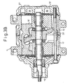
- a refrigerating system shown in Fig. 3A is similar to that of the first embodiment mentioned above, but a fixed displacement type compressor as shown in Fig. 3B is used as a compressor 1', a suction throttle valve 7 is provided upstream from the compressor 1' in a pipe 6e between the compressor 1' and an accumulator 5, and the control means 40 and the pressure sensors 41, 42 are eliminated.
- a swash plate 23' in which the inclination angle is fixed is used in the fixed displacement type compressor shown in Fig. 3B.
- the same parts as in Fig. 1 are indicated by the same reference numerals while adding a dash (') to differentiate them.
- the opening degree of the suction throttle valve 7 is controlled based on a detected value of a refrigerant pressure at the exit of evaporator 4, i.e., the lower evaporating pressure. If the lower evaporating pressure is higher than the preset value, the opening degree thereof is made to increase, while if the lower evaporating pressure is lower than the preset value, the opening degree is made to reduce.
- the opening degree of the suction throttle valve 7 increases, the suction pressure of the compressor 1' increase to lower the lower evaporating pressure so that the refrigerating performance becomes higher.
- the opening degree of the throttle valve 7 is reduced, the suction pressure of the compressor 1' lowers to increase the lower evaporating pressure so that the refrigerating performance becomes lower. In such a manner, the refrigerating performance is adjustable in accordance with the lower evaporating pressure.
- a refrigerating system shown in Fig. 4 has the same structure as that of the first embodiment, except that a fixed displacement type compressor is used as the compressor 1' and controlled in an ON-OFF manner in accordance with the detected results of the evaporating pressure, and the control means 40 and the pressure sensors 41, 42 are eliminated.
- the refrigerant temperature is detected at the exit of the evaporator 4.
- a first preset temperature t 1 an electromagnetic clutch of the compressor 1' is turned off, while when an evaporating temperature is higher than a second preset temperature t 2 (> t 1 ), the electromagnetic clutch of the compressor 1' is turned on.
- the evaporating temperature corresponds to the evaporating pressure.
Landscapes
- Engineering & Computer Science (AREA)
- Mechanical Engineering (AREA)
- General Engineering & Computer Science (AREA)
- Physics & Mathematics (AREA)
- Thermal Sciences (AREA)
- Chemical & Material Sciences (AREA)
- Chemical Kinetics & Catalysis (AREA)
- Air-Conditioning For Vehicles (AREA)
- Compression-Type Refrigeration Machines With Reversible Cycles (AREA)
- Compressors, Vaccum Pumps And Other Relevant Systems (AREA)
Applications Claiming Priority (2)
| Application Number | Priority Date | Filing Date | Title |
|---|---|---|---|
| JP10672198A JP4075129B2 (ja) | 1998-04-16 | 1998-04-16 | 冷房装置の制御方法 |
| JP10672198 | 1998-04-16 |
Publications (3)
| Publication Number | Publication Date |
|---|---|
| EP0952412A2 EP0952412A2 (en) | 1999-10-27 |
| EP0952412A3 EP0952412A3 (en) | 2002-01-16 |
| EP0952412B1 true EP0952412B1 (en) | 2005-11-16 |
Family
ID=14440826
Family Applications (1)
| Application Number | Title | Priority Date | Filing Date |
|---|---|---|---|
| EP99106297A Expired - Lifetime EP0952412B1 (en) | 1998-04-16 | 1999-04-16 | Refrigerating system and method of operating the same |
Country Status (4)
| Country | Link |
|---|---|
| US (1) | US6105380A (ja) |
| EP (1) | EP0952412B1 (ja) |
| JP (1) | JP4075129B2 (ja) |
| DE (1) | DE69928317T2 (ja) |
Families Citing this family (37)
| Publication number | Priority date | Publication date | Assignee | Title |
|---|---|---|---|---|
| JP2000111176A (ja) * | 1998-10-05 | 2000-04-18 | Toyota Autom Loom Works Ltd | 空調装置 |
| JP2001191789A (ja) * | 2000-01-14 | 2001-07-17 | Toyota Autom Loom Works Ltd | 容量可変型圧縮機および空調装置 |
| JP3917347B2 (ja) * | 2000-05-18 | 2007-05-23 | 株式会社豊田自動織機 | 車両用空調装置 |
| JP2001328424A (ja) * | 2000-05-19 | 2001-11-27 | Toyota Industries Corp | 空調装置 |
| US6357242B1 (en) * | 2000-07-20 | 2002-03-19 | Delphi Technologies, Inc. | Control system and method for suppressing head pressure spikes in a vehicle air conditioning system |
| JP2003002048A (ja) * | 2000-08-28 | 2003-01-08 | Denso Corp | 車両用空調装置 |
| NO20005974D0 (no) * | 2000-11-24 | 2000-11-24 | Sinvent As | Kjöle- eller varmepumpesystem med varmeavgivelse ved endring i temperatur |
| JP2002274147A (ja) * | 2001-01-12 | 2002-09-25 | Japan Climate Systems Corp | 車両用空調装置 |
| WO2003019085A1 (en) * | 2001-08-31 | 2003-03-06 | Mærsk Container Industri A/S | A vapour-compression-cycle device |
| US6840054B2 (en) | 2001-12-21 | 2005-01-11 | Visteon Global Technologies, Inc. | Control strategy of a variable displacement compressor operating at super critical pressures |
| US6568199B1 (en) | 2002-01-22 | 2003-05-27 | Carrier Corporation | Method for optimizing coefficient of performance in a transcritical vapor compression system |
| US6715995B2 (en) | 2002-01-31 | 2004-04-06 | Visteon Global Technologies, Inc. | Hybrid compressor control method |
| US6694763B2 (en) * | 2002-05-30 | 2004-02-24 | Praxair Technology, Inc. | Method for operating a transcritical refrigeration system |
| US6631617B1 (en) | 2002-06-27 | 2003-10-14 | Tecumseh Products Company | Two stage hermetic carbon dioxide compressor |
| US6626000B1 (en) | 2002-10-30 | 2003-09-30 | Visteon Global Technologies, Inc. | Method and system for electronically controlled high side pressure regulation in a vapor compression cycle |
| JP4143434B2 (ja) * | 2003-02-03 | 2008-09-03 | カルソニックカンセイ株式会社 | 超臨界冷媒を用いた車両用空調装置 |
| DE10306394A1 (de) * | 2003-02-15 | 2004-08-26 | Volkswagen Ag | Kältemittelkreislauf mit einem geregelten Taumelscheibenkompressor |
| DE102004041251A1 (de) * | 2003-09-02 | 2005-03-24 | Luk Fahrzeug-Hydraulik Gmbh & Co Kg | Kompressor oder Klimaanlage |
| JP2005265278A (ja) * | 2004-03-18 | 2005-09-29 | Daikin Ind Ltd | 冷凍装置 |
| WO2006108056A1 (en) * | 2005-04-05 | 2006-10-12 | The Product Group, Llc | Intelligent controller for refrigerating and air conditioning systems |
| US20060230773A1 (en) * | 2005-04-14 | 2006-10-19 | Carrier Corporation | Method for determining optimal coefficient of performance in a transcritical vapor compression system |
| DE102005031511A1 (de) * | 2005-07-06 | 2007-01-11 | Daimlerchrysler Ag | Steuerungsventil für einen Kältemittelverdichter und Kältemittelverdichter |
| US7584625B2 (en) * | 2005-10-21 | 2009-09-08 | Emerson Climate Technologies, Inc. | Compressor capacity modulation system and method |
| JP2008057497A (ja) * | 2006-09-01 | 2008-03-13 | Toyota Industries Corp | 電磁クラッチ付回転装置 |
| US20080196425A1 (en) * | 2006-11-14 | 2008-08-21 | Temple Keith A | Method for evaluating refrigeration cycle performance |
| US8087256B2 (en) * | 2007-11-02 | 2012-01-03 | Cryomechanics, LLC | Cooling methods and systems using supercritical fluids |
| US8720213B2 (en) * | 2008-02-19 | 2014-05-13 | Delphi Technologies, Inc. | Variable displacement compressor with a compensated suction shufoff valve |
| FR2938050B1 (fr) * | 2008-11-06 | 2013-01-18 | Valeo Systemes Thermiques Branche Thermique Habitacle | Boucle de climatisation comprenant une vanne en entree du compresseur |
| DE102011006165B4 (de) * | 2011-03-25 | 2014-10-09 | Bruker Biospin Ag | Kühlvorrichtung mit einstellbarer Verdampfungstemperatur |
| US20130091874A1 (en) * | 2011-04-07 | 2013-04-18 | Liebert Corporation | Variable Refrigerant Flow Cooling System |
| JP6398897B2 (ja) * | 2015-07-23 | 2018-10-03 | 株式会社豊田自動織機 | 遠心圧縮機 |
| US10472072B2 (en) * | 2015-11-25 | 2019-11-12 | Hamilton Sundstrand Corporation | Supply tube for sensor |
| US10323870B2 (en) * | 2016-04-06 | 2019-06-18 | Heatcraft Refrigeration Products Llc | Optimizing liquid temperature and liquid pressure in a modular outdoor refrigeration system |
| BE1026036B1 (nl) * | 2018-02-23 | 2019-09-20 | Atlas Copco Airpower Nv | Werkwijze voor het aansturen van een compressorinrichting en compressorinrichting |
| KR20220131598A (ko) * | 2021-03-22 | 2022-09-29 | 현대자동차주식회사 | 컴프레서 제어 장치 및 제어 방법 |
| US20230076358A1 (en) * | 2021-09-09 | 2023-03-09 | Haier Us Appliance Solutions, Inc. | Indoor garden center environmental control system |
| WO2023170848A1 (ja) * | 2022-03-10 | 2023-09-14 | 三菱電機株式会社 | 冷凍サイクル装置の制御装置、室外ユニットおよび冷凍サイクル装置 |
Family Cites Families (18)
| Publication number | Priority date | Publication date | Assignee | Title |
|---|---|---|---|---|
| GB1544804A (en) * | 1977-05-02 | 1979-04-25 | Commercial Refrigeration Ltd | Apparatus for and methods of transferring heat between bodies of fluid or other substance |
| JPS60171989U (ja) * | 1984-04-25 | 1985-11-14 | 株式会社ボッシュオートモーティブ システム | カ−ク−ラ用ベ−ン型圧縮機 |
| US4732544A (en) * | 1986-06-12 | 1988-03-22 | Diesel Kiki Co., Ltd. | Variable capacity wobble plate compressor |
| JPH01102256A (ja) * | 1987-10-13 | 1989-04-19 | Toyota Autom Loom Works Ltd | 圧縮機の運転制御方法 |
| JPH01142276A (ja) * | 1987-11-27 | 1989-06-05 | Sanden Corp | 容量可変型斜板式圧縮機 |
| US5245836A (en) * | 1989-01-09 | 1993-09-21 | Sinvent As | Method and device for high side pressure regulation in transcritical vapor compression cycle |
| JP2780301B2 (ja) * | 1989-02-02 | 1998-07-30 | 株式会社豊田自動織機製作所 | スクロール型圧縮機における容量可変機構 |
| CA2119015C (en) | 1991-09-16 | 2002-07-09 | Gustav Lorentzen | Method of high-side pressure regulation in transcritical vapor compression cycle device |
| NO915127D0 (no) * | 1991-12-27 | 1991-12-27 | Sinvent As | Kompresjonsanordning med variabelt volum |
| JP3082485B2 (ja) * | 1992-12-11 | 2000-08-28 | 株式会社豊田自動織機製作所 | 揺動斜板式可変容量圧縮機 |
| NO175830C (no) * | 1992-12-11 | 1994-12-14 | Sinvent As | Kompresjonskjölesystem |
| US5577894A (en) * | 1993-11-05 | 1996-11-26 | Kabushiki Kaisha Toyoda Jidoshokki Seisakusho | Piston type variable displacement compressor |
| DE4432272C2 (de) * | 1994-09-09 | 1997-05-15 | Daimler Benz Ag | Verfahren zum Betreiben einer Kälteerzeugungsanlage für das Klimatisieren von Fahrzeugen und eine Kälteerzeugungsanlage zur Durchführung desselben |
| CH690189A5 (de) * | 1995-03-10 | 2000-05-31 | Daimler Benz Ag | Verfahren zur Regelung der Leistung einer Anlage für die Kühlung des Fahrgastraumes eines Kraftfahrzeuges. |
| CH689826A5 (de) * | 1995-05-10 | 1999-12-15 | Daimler Benz Ag | Fahrzeug-Klimaanlage. |
| JPH09329087A (ja) * | 1996-06-11 | 1997-12-22 | Toyota Autom Loom Works Ltd | 可変容量型圧縮機の制御装置 |
| JP3467989B2 (ja) * | 1996-09-13 | 2003-11-17 | 株式会社日本自動車部品総合研究所 | 蒸気圧縮式冷凍サイクル |
| JP3900669B2 (ja) * | 1998-04-16 | 2007-04-04 | 株式会社豊田自動織機 | 制御弁及び可変容量型圧縮機 |
-
1998
- 1998-04-16 JP JP10672198A patent/JP4075129B2/ja not_active Expired - Fee Related
-
1999
- 1999-04-15 US US09/292,409 patent/US6105380A/en not_active Expired - Lifetime
- 1999-04-16 EP EP99106297A patent/EP0952412B1/en not_active Expired - Lifetime
- 1999-04-16 DE DE69928317T patent/DE69928317T2/de not_active Expired - Lifetime
Also Published As
| Publication number | Publication date |
|---|---|
| US6105380A (en) | 2000-08-22 |
| JP4075129B2 (ja) | 2008-04-16 |
| DE69928317D1 (de) | 2005-12-22 |
| DE69928317T2 (de) | 2006-08-10 |
| JPH11294876A (ja) | 1999-10-29 |
| EP0952412A2 (en) | 1999-10-27 |
| EP0952412A3 (en) | 2002-01-16 |
Similar Documents
| Publication | Publication Date | Title |
|---|---|---|
| EP0952412B1 (en) | Refrigerating system and method of operating the same | |
| EP0309242B1 (en) | Refrigerating system having a compressor with an internally and externally controlled variable displacement mechanism | |
| US5823000A (en) | Refrigerant circuit with fluid flow control mechanism | |
| US4905477A (en) | Refrigerant circuit with passageway control mechanism | |
| US6260369B1 (en) | Flow control valve for a variable displacement refrigerant compressor | |
| EP0935107B1 (en) | Method and apparatus for controlling variable displacement compressor | |
| US5189886A (en) | Refrigerating system having a compressor with an internally and externally controlled variable displacement mechanism | |
| US5027612A (en) | Refrigerating system having a compressor with an internally and externally controlled variable displacement mechanism | |
| US6250093B1 (en) | Air conditioning system and compressor | |
| US6848262B2 (en) | Compressor device and control method for the same | |
| JP2001012358A (ja) | 冷凍サイクルの可変容量制御装置 | |
| US6321545B1 (en) | Control apparatus for variable displacement type compressor | |
| US20030035733A1 (en) | Compression capacity control device for refrigeration cycle | |
| JPH01190972A (ja) | 可変容量式斜板型圧縮機 | |
| US5168716A (en) | Refrigeration system having a compressor with an internally and externally controlled variable displacement mechanism | |
| JP3752816B2 (ja) | 可変容量型圧縮機の動作制御方法及び動作制御装置 | |
| JPH03134268A (ja) | 可変容量式斜板型圧縮機 | |
| JPH03199677A (ja) | 可変容量式斜板型圧縮機 | |
| EP1014016A2 (en) | Air conditioning systems | |
| JPH08165987A (ja) | 可変容量型圧縮機の動作制御システム | |
| JP4118413B2 (ja) | 容量可変斜板式コンプレッサ | |
| JPH11223179A (ja) | 可変容量型圧縮機の動作制御方法及び動作制御装置 | |
| JPH01101219A (ja) | 車両用空調装置のコンプレツサ構造 | |
| JP3319652B2 (ja) | 可変容量型圧縮機を用いた冷凍回路 | |
| JP3319653B2 (ja) | クラッチレス可変容量型圧縮機を用いた冷凍回路 |
Legal Events
| Date | Code | Title | Description |
|---|---|---|---|
| PUAI | Public reference made under article 153(3) epc to a published international application that has entered the european phase |
Free format text: ORIGINAL CODE: 0009012 |
|
| 17P | Request for examination filed |
Effective date: 19990416 |
|
| AK | Designated contracting states |
Kind code of ref document: A2 Designated state(s): AT BE CH CY DE DK ES FI FR GB GR IE IT LI LU MC NL PT SE Kind code of ref document: A2 Designated state(s): DE FR IT |
|
| AX | Request for extension of the european patent |
Free format text: AL;LT;LV;MK;RO;SI |
|
| PUAL | Search report despatched |
Free format text: ORIGINAL CODE: 0009013 |
|
| RAP1 | Party data changed (applicant data changed or rights of an application transferred) |
Owner name: DENSO CORPORATION Owner name: KABUSHIKI KAISHA TOYOTA JIDOSHOKKI |
|
| AK | Designated contracting states |
Kind code of ref document: A3 Designated state(s): AT BE CH CY DE DK ES FI FR GB GR IE IT LI LU MC NL PT SE |
|
| AX | Request for extension of the european patent |
Free format text: AL;LT;LV;MK;RO;SI |
|
| AKX | Designation fees paid |
Free format text: DE FR IT |
|
| 17Q | First examination report despatched |
Effective date: 20031009 |
|
| GRAP | Despatch of communication of intention to grant a patent |
Free format text: ORIGINAL CODE: EPIDOSNIGR1 |
|
| GRAS | Grant fee paid |
Free format text: ORIGINAL CODE: EPIDOSNIGR3 |
|
| GRAA | (expected) grant |
Free format text: ORIGINAL CODE: 0009210 |
|
| RAP1 | Party data changed (applicant data changed or rights of an application transferred) |
Owner name: KABUSHIKI KAISHA TOYOTA JIDOSHOKKI |
|
| RAP1 | Party data changed (applicant data changed or rights of an application transferred) |
Owner name: KABUSHIKI KAISHA TOYOTA JIDOSHOKKI |
|
| AK | Designated contracting states |
Kind code of ref document: B1 Designated state(s): DE FR IT |
|
| REF | Corresponds to: |
Ref document number: 69928317 Country of ref document: DE Date of ref document: 20051222 Kind code of ref document: P |
|
| ET | Fr: translation filed | ||
| PLBE | No opposition filed within time limit |
Free format text: ORIGINAL CODE: 0009261 |
|
| STAA | Information on the status of an ep patent application or granted ep patent |
Free format text: STATUS: NO OPPOSITION FILED WITHIN TIME LIMIT |
|
| 26N | No opposition filed |
Effective date: 20060817 |
|
| PGFP | Annual fee paid to national office [announced via postgrant information from national office to epo] |
Ref country code: DE Payment date: 20120425 Year of fee payment: 14 |
|
| PGFP | Annual fee paid to national office [announced via postgrant information from national office to epo] |
Ref country code: FR Payment date: 20120504 Year of fee payment: 14 |
|
| PGFP | Annual fee paid to national office [announced via postgrant information from national office to epo] |
Ref country code: IT Payment date: 20120418 Year of fee payment: 14 |
|
| PG25 | Lapsed in a contracting state [announced via postgrant information from national office to epo] |
Ref country code: DE Free format text: LAPSE BECAUSE OF NON-PAYMENT OF DUE FEES Effective date: 20131101 |
|
| REG | Reference to a national code |
Ref country code: FR Ref legal event code: ST Effective date: 20131231 |
|
| REG | Reference to a national code |
Ref country code: DE Ref legal event code: R119 Ref document number: 69928317 Country of ref document: DE Effective date: 20131101 |
|
| PG25 | Lapsed in a contracting state [announced via postgrant information from national office to epo] |
Ref country code: IT Free format text: LAPSE BECAUSE OF NON-PAYMENT OF DUE FEES Effective date: 20130416 Ref country code: FR Free format text: LAPSE BECAUSE OF NON-PAYMENT OF DUE FEES Effective date: 20130430 |