EP0950593A2 - Hydraulisches Bremssystem mit einem druckunterstüzten Bremszylinderkolben - Google Patents
Hydraulisches Bremssystem mit einem druckunterstüzten Bremszylinderkolben Download PDFInfo
- Publication number
- EP0950593A2 EP0950593A2 EP99106961A EP99106961A EP0950593A2 EP 0950593 A2 EP0950593 A2 EP 0950593A2 EP 99106961 A EP99106961 A EP 99106961A EP 99106961 A EP99106961 A EP 99106961A EP 0950593 A2 EP0950593 A2 EP 0950593A2
- Authority
- EP
- European Patent Office
- Prior art keywords
- chamber
- pressure
- fluid
- assisting
- pressurizing
- Prior art date
- Legal status (The legal status is an assumption and is not a legal conclusion. Google has not performed a legal analysis and makes no representation as to the accuracy of the status listed.)
- Granted
Links
Images


Classifications
-
- B—PERFORMING OPERATIONS; TRANSPORTING
- B60—VEHICLES IN GENERAL
- B60T—VEHICLE BRAKE CONTROL SYSTEMS OR PARTS THEREOF; BRAKE CONTROL SYSTEMS OR PARTS THEREOF, IN GENERAL; ARRANGEMENT OF BRAKING ELEMENTS ON VEHICLES IN GENERAL; PORTABLE DEVICES FOR PREVENTING UNWANTED MOVEMENT OF VEHICLES; VEHICLE MODIFICATIONS TO FACILITATE COOLING OF BRAKES
- B60T13/00—Transmitting braking action from initiating means to ultimate brake actuator with power assistance or drive; Brake systems incorporating such transmitting means, e.g. air-pressure brake systems
- B60T13/74—Transmitting braking action from initiating means to ultimate brake actuator with power assistance or drive; Brake systems incorporating such transmitting means, e.g. air-pressure brake systems with electrical assistance or drive
-
- B—PERFORMING OPERATIONS; TRANSPORTING
- B60—VEHICLES IN GENERAL
- B60T—VEHICLE BRAKE CONTROL SYSTEMS OR PARTS THEREOF; BRAKE CONTROL SYSTEMS OR PARTS THEREOF, IN GENERAL; ARRANGEMENT OF BRAKING ELEMENTS ON VEHICLES IN GENERAL; PORTABLE DEVICES FOR PREVENTING UNWANTED MOVEMENT OF VEHICLES; VEHICLE MODIFICATIONS TO FACILITATE COOLING OF BRAKES
- B60T8/00—Arrangements for adjusting wheel-braking force to meet varying vehicular or ground-surface conditions, e.g. limiting or varying distribution of braking force
- B60T8/32—Arrangements for adjusting wheel-braking force to meet varying vehicular or ground-surface conditions, e.g. limiting or varying distribution of braking force responsive to a speed condition, e.g. acceleration or deceleration
- B60T8/34—Arrangements for adjusting wheel-braking force to meet varying vehicular or ground-surface conditions, e.g. limiting or varying distribution of braking force responsive to a speed condition, e.g. acceleration or deceleration having a fluid pressure regulator responsive to a speed condition
- B60T8/36—Arrangements for adjusting wheel-braking force to meet varying vehicular or ground-surface conditions, e.g. limiting or varying distribution of braking force responsive to a speed condition, e.g. acceleration or deceleration having a fluid pressure regulator responsive to a speed condition including a pilot valve responding to an electromagnetic force
- B60T8/3615—Electromagnetic valves specially adapted for anti-lock brake and traction control systems
- B60T8/3655—Continuously controlled electromagnetic valves
- B60T8/366—Valve details
- B60T8/367—Seat valves, e.g. poppet valves
-
- B—PERFORMING OPERATIONS; TRANSPORTING
- B60—VEHICLES IN GENERAL
- B60T—VEHICLE BRAKE CONTROL SYSTEMS OR PARTS THEREOF; BRAKE CONTROL SYSTEMS OR PARTS THEREOF, IN GENERAL; ARRANGEMENT OF BRAKING ELEMENTS ON VEHICLES IN GENERAL; PORTABLE DEVICES FOR PREVENTING UNWANTED MOVEMENT OF VEHICLES; VEHICLE MODIFICATIONS TO FACILITATE COOLING OF BRAKES
- B60T13/00—Transmitting braking action from initiating means to ultimate brake actuator with power assistance or drive; Brake systems incorporating such transmitting means, e.g. air-pressure brake systems
- B60T13/10—Transmitting braking action from initiating means to ultimate brake actuator with power assistance or drive; Brake systems incorporating such transmitting means, e.g. air-pressure brake systems with fluid assistance, drive, or release
- B60T13/66—Electrical control in fluid-pressure brake systems
- B60T13/68—Electrical control in fluid-pressure brake systems by electrically-controlled valves
- B60T13/686—Electrical control in fluid-pressure brake systems by electrically-controlled valves in hydraulic systems or parts thereof
-
- B—PERFORMING OPERATIONS; TRANSPORTING
- B60—VEHICLES IN GENERAL
- B60T—VEHICLE BRAKE CONTROL SYSTEMS OR PARTS THEREOF; BRAKE CONTROL SYSTEMS OR PARTS THEREOF, IN GENERAL; ARRANGEMENT OF BRAKING ELEMENTS ON VEHICLES IN GENERAL; PORTABLE DEVICES FOR PREVENTING UNWANTED MOVEMENT OF VEHICLES; VEHICLE MODIFICATIONS TO FACILITATE COOLING OF BRAKES
- B60T8/00—Arrangements for adjusting wheel-braking force to meet varying vehicular or ground-surface conditions, e.g. limiting or varying distribution of braking force
- B60T8/32—Arrangements for adjusting wheel-braking force to meet varying vehicular or ground-surface conditions, e.g. limiting or varying distribution of braking force responsive to a speed condition, e.g. acceleration or deceleration
- B60T8/321—Arrangements for adjusting wheel-braking force to meet varying vehicular or ground-surface conditions, e.g. limiting or varying distribution of braking force responsive to a speed condition, e.g. acceleration or deceleration deceleration
- B60T8/3255—Systems in which the braking action is dependent on brake pedal data
- B60T8/3275—Systems with a braking assistant function, i.e. automatic full braking initiation in dependence of brake pedal velocity
-
- B—PERFORMING OPERATIONS; TRANSPORTING
- B60—VEHICLES IN GENERAL
- B60T—VEHICLE BRAKE CONTROL SYSTEMS OR PARTS THEREOF; BRAKE CONTROL SYSTEMS OR PARTS THEREOF, IN GENERAL; ARRANGEMENT OF BRAKING ELEMENTS ON VEHICLES IN GENERAL; PORTABLE DEVICES FOR PREVENTING UNWANTED MOVEMENT OF VEHICLES; VEHICLE MODIFICATIONS TO FACILITATE COOLING OF BRAKES
- B60T8/00—Arrangements for adjusting wheel-braking force to meet varying vehicular or ground-surface conditions, e.g. limiting or varying distribution of braking force
- B60T8/32—Arrangements for adjusting wheel-braking force to meet varying vehicular or ground-surface conditions, e.g. limiting or varying distribution of braking force responsive to a speed condition, e.g. acceleration or deceleration
- B60T8/34—Arrangements for adjusting wheel-braking force to meet varying vehicular or ground-surface conditions, e.g. limiting or varying distribution of braking force responsive to a speed condition, e.g. acceleration or deceleration having a fluid pressure regulator responsive to a speed condition
- B60T8/44—Arrangements for adjusting wheel-braking force to meet varying vehicular or ground-surface conditions, e.g. limiting or varying distribution of braking force responsive to a speed condition, e.g. acceleration or deceleration having a fluid pressure regulator responsive to a speed condition co-operating with a power-assist booster means associated with a master cylinder for controlling the release and reapplication of brake pressure through an interaction with the power assist device, i.e. open systems
- B60T8/441—Arrangements for adjusting wheel-braking force to meet varying vehicular or ground-surface conditions, e.g. limiting or varying distribution of braking force responsive to a speed condition, e.g. acceleration or deceleration having a fluid pressure regulator responsive to a speed condition co-operating with a power-assist booster means associated with a master cylinder for controlling the release and reapplication of brake pressure through an interaction with the power assist device, i.e. open systems using hydraulic boosters
-
- B—PERFORMING OPERATIONS; TRANSPORTING
- B60—VEHICLES IN GENERAL
- B60T—VEHICLE BRAKE CONTROL SYSTEMS OR PARTS THEREOF; BRAKE CONTROL SYSTEMS OR PARTS THEREOF, IN GENERAL; ARRANGEMENT OF BRAKING ELEMENTS ON VEHICLES IN GENERAL; PORTABLE DEVICES FOR PREVENTING UNWANTED MOVEMENT OF VEHICLES; VEHICLE MODIFICATIONS TO FACILITATE COOLING OF BRAKES
- B60T8/00—Arrangements for adjusting wheel-braking force to meet varying vehicular or ground-surface conditions, e.g. limiting or varying distribution of braking force
- B60T8/32—Arrangements for adjusting wheel-braking force to meet varying vehicular or ground-surface conditions, e.g. limiting or varying distribution of braking force responsive to a speed condition, e.g. acceleration or deceleration
- B60T8/34—Arrangements for adjusting wheel-braking force to meet varying vehicular or ground-surface conditions, e.g. limiting or varying distribution of braking force responsive to a speed condition, e.g. acceleration or deceleration having a fluid pressure regulator responsive to a speed condition
- B60T8/48—Arrangements for adjusting wheel-braking force to meet varying vehicular or ground-surface conditions, e.g. limiting or varying distribution of braking force responsive to a speed condition, e.g. acceleration or deceleration having a fluid pressure regulator responsive to a speed condition connecting the brake actuator to an alternative or additional source of fluid pressure, e.g. traction control systems
- B60T8/4809—Traction control, stability control, using both the wheel brakes and other automatic braking systems
- B60T8/4827—Traction control, stability control, using both the wheel brakes and other automatic braking systems in hydraulic brake systems
- B60T8/4845—Traction control, stability control, using both the wheel brakes and other automatic braking systems in hydraulic brake systems using a booster or a master cylinder for traction control
Definitions
- the present invention relates in general to a hydraulically operated braking system, and more particularly to a hydraulically operated braking system including an assisting device for boosting a drive force to be applied to a pressurizing piston of a master cylinder.
- This braking system includes (1) a master cylinder having a pressurizing piston operatively connected to a brake operating member to pressurize a working fluid in a pressurizing chamber, (2) a brake cylinder for actuating a brake device based on the pressure of the pressurized fluid, and (3) an assisting device for applying to the pressurizing piston an assisting drive force which is different than a primary drive force to be applied to the pressurizing piston on the basis of a brake operating force acting on the brake operating member.
- the fluid pressure in the pressurizing chamber can be boosted, permitting the brake device to produce an increased braking force for a given value of the brake operating force.
- the assisting drive force to be generated by the assisting device is simply proportional to the brake operating force. That is, the assisting device disclosed in the above-identified publication is not capable of producing the assisting drive force which is not proportional to the brake operating force.
- It is therefore an object of this invention to provide a hydraulically operated braking system comprising an assisting device capable of producing an assisting drive force in a non-proportional relationship with the brake operating force.
- the hydraulically braking system shown therein includes a normal braking system and a servo system which are independent of each other.
- the normal braking system includes a brake operating member in the form of a brake pedal 10, a master cylinder 12, and wheel brake cylinders 22, 24, 26, 28 for respective wheels 14, 16, 18, 20 of an automotive vehicle.
- the master cylinder 12 is a tandem type cylinder having two pressurizing chambers 30 and 32. A pressure of a working fluid in these pressurizing chambers 30, 32 are pressurized by an advancing movement of a pressurizing piston 34 operatively connected to the brake pedal 10. The fluid pressure in the pressurizing chambers 30, 32 changes with an operating force acting on the brake pedal 10.
- Two fluid passages 36, 38 are connected to the respective pressurizing chambers 30, 32.
- Each of the fluid passages 36, 38 is split into two branches.
- the wheel brake cylinders 22, 24 are connected to the ends of the two branches of the fluid passage 36, while the wheel brake cylinders 26, 28 are connected to the ends of the two branches of the fluid passage 38.
- a pressure holding valve in the form of a solenoid-operated shut-off valve 44.
- the branches of each fluid passage 36, 38 are connected to a reservoir 46 through fluid passages 47.
- a check valve 49 is provided in a by-pass passage which by-passes each of the foul pressure holding shut-off valves 44.
- Each of the check valves 49 allows a fluid flow in a direction from the corresponding wheel brake cylinder 22, 24, 26, 28 towards the master cylinder 12, and inhibits a fluid flow in the opposite direction.
- the check valves 49 permit the fluid to be rapidly returned from the wheel brake cylinders 22, 24, 26, 28 to the master cylinder 12 when the brake pedal 10 is released from an operated position towards the non-operated position while the pressure holding shut-off valves 44 are placed in their closed positions.
- the two reservoirs 46 are connected to the respective fluid passages 36, 38 also through respective fluid passages 50.
- the pump 56 is disposed between the two check valves 52, 54.
- the damper 58 functions to reduce pressure pulsation of the fluid delivered from the pump 56.
- the two pumps 56 are driven by a common electric motor 60.
- shut-off valve 62 In a portion of the fluid passage 36 between the pressurizing chamber 30 and the point of branching, there is provided a solenoid-operated shut-off valve 62.
- a stroke adjusting cylinder 64 is connected to a portion of the fluid passage 36 between the shut-off valve 62 and the point of branching.
- the servo system of the present hydraulically operated braking system includes a pump 70, an accumulator 72, a pressure increase control valve 74, a pressure reduction control valve 76, a master reservoir 76 and an assisting cylinder 78.
- the pressure increase control valve 74 and the pressure reduction control valve 75 are controlled by a pressure control device 80 which is constituted principally by a computer. It will be understood from the following description that the above-indicated elements 70-78 and a portion of the pressure control device 80 assigned to control the control valves 74, 75 cooperate to constitute an assisting device 81 for boosting a drive force to be applied to the pressurizing piston 32 of the master cylinder 10. It will also be understood that the pressure increase control valve 74 and the pressure reduction control valve 75 constitute a major portion of a solenoid-operated pressure control valve device 82 of the assisting device 81.
- the working fluid in the master reservoir 76 is pumped up and pressurized by the pump 70, and the pressurized fluid is stored in the accumulator 72.
- a pressure switch 83 is provided to monitor whether the pressure of the fluid stored in the accumulator 72 falls within a predetermined range.
- An electric motor 84 for driving the pump 70 is controlled according to an output signal of the pressure switch 83, so that the fluid pressure in the accumulator 72 is held substantially within the predetermined range.
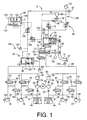
- the pressure switch 83 has a plurality of switching portions, so that the pressure switch 83 is turned OFF when the fluid pressure in the accumulator 72 (hereinafter referred to as "accumulator pressure") is lowered below a predetermined lower limit, and is turned ON when the accumulator pressure rises above a predetermined upper limit, as indicated in the graph of Fig. 7.
- the electric motor 84 is turned ON when the pressure switch 83 is turned OFF, and is turned OFF when the pressure switch 83 is turned ON.
- the electric motor 84 is kept operated while the pressure switch 83 is OFF, so that the accumulator pressure is held within the predetermined range defined by the lower and upper limits indicated above.
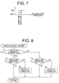
- the electric motor 84 is controlled by the pressure control device 80 depending upon the output signal of the pressure switch 83, according to a motor control routine illustrated in the flow chart of Fig. 8. This routine is initiated with step S1 to determine whether the electric motor 84 is in operation. If a negative decision (NO) is obtained in step S1, the control flow goes to step S2 to determine whether the pressure switch 83 is in the ON state. If the pressure switch 83 is in the ON state, the electric motor 84 is held OFF. If the pressure switch 83 is in the OFF state, that is, if the accumulator pressure is lower than the lower limit, a negative decision (NO) is obtained in step S2, and the control flow goes to step S3 to turn ON the electric motor 84.
- NO negative decision
- step S4 is implemented to determine whether the pressure switch 83 is in the ON state. If the pressure switch 83 is in the ON state, that is, if the accumulator pressure is higher than the upper limit, a negative decision (NO) is obtained in step S4, and the control flow goes to step S4 to turn OFF the electric motor 60. If an affirmative decision (YES) is obtained in step S4, the electric motor 84 is held in operation.
- a pressure relief valve 86 is provided between the delivery side of the pump 70 and the reservoir 76, to prevent an excessive rise of the delivery pressure of the pump 70.
- the assisting cylinder 78 includes a cylinder housing 90, an assisting piston 92 fluid-tightly and slidably received in the cylinder housing 90, and a return spring 94 disposed between the assisting piston 92 and one of the opposite axial ends of the cylinder housing 90.
- the assisting piston 92 is operatively connected to the brake pedal 10 by a piston rod 95.
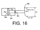
- the brake pedal 10 has a fulcrum 96 at an intermediate portion thereof between the lower end having a pedal pad 97 and the upper end.
- the piston rod 95 engages a portion of the brake pedal 10 between the fulcrum 96 and the upper end, more precisely, near the upper end.
- the pressurizing piston 34 of the master cylinder 12 is operatively connected by a piston rod 98 to a portion of the brake pedal 10 between the brake pad 97 and the fulcrum 96. As indicated in Fig.
- the points of engagement of the rods 95, 98 with the brake pedal 10 and the fulcrum 96 line on a straight line, and the fulcrum 96 is spaced from the center of the pedal pad 97 by a distance L F in the direction parallel to the straight line.
- the point of engagement of the rod 98 with the brake pedal 10 is spaced from the fulcrum 96 by a distance L M
- the point of engagement of the rod 95 with the brake pedal 10 is spaced from the fulcrum 96 by a distance L S .
- the brake pedal 10 has elongate two elongate holes 99a while the rods 98, 95 have respective pins 99b engaging the respective elongate holes 99a.
- the engaging ends of the rods 98, 95 are movable in the longitudinal direction of the brake pedal 10 while maintaining the predetermined constant distances L M , L S between the fulcrum 96 and the engaging ends.
- the cylinder housing 90 and the assisting piston 92 cooperate to define a spring chamber and an assisting pressure chamber 100 on the opposite sides of the assisting piston 92.
- the return spring 94 is disposed in the spring chamber, which communicates with the atmosphere.
- the assisting pressure chamber 100 communicates with the accumulator 72 and the master reservoir 76 through the pressure increase control valve 74 and the pressure reduction control valve 75, respectively.
- the fluid pressure in the assisting pressure chamber 100 is controllable by controlling the control valves 74, 75.
- the pressure increase and pressure reduction control valves 74 and 75 are identical in construction with each other. The following description of the pressure increase control valve 74 substantially applies to the pressure reduction control valve 75.
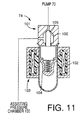
- Tile pressure reduction control valve 74 is disposed between the delivery side of the pump 70 and the assisting pressure chamber 100. As shown in Fig. 11, the pressure reduction control valve 74 includes an electromagnetic force generating device 103, and a spring 104.
- the electromagnetic force generating device 103 includes a seating valve 101 and a coil 102.
- the seating valve 101 has a valve member 105 and a valve seat 106. A force corresponding to a fluid pressure difference across the seating valve 101 acts on the valve member 105 in a direction that causes the valve member 105 to be spaced away from the valve seat 106.
- a biasing force of the spring 104 acts on the valve member 105 in a direction that causes the valve member 105 to be seated on the valve seat 106.
- an electromagnetic force generated by application of an electric current to the coil 102 of the electromagnetic force generating device 103 acts on the valve member 105 so as to move it away from the valve seat 106.
- the electromagnetic force can be controlled by controlling the electric current applied to the coil 102.
- the force based on the fluid pressure difference, the electromagnetic force and the biasing force of the spring 104 act on the valve member 105 of the pressure increase control valve 74.
- the force based on the fluid pressure difference and the electromagnetic force act on the valve member 105 in the same direction, so as to move the valve member 104 away from the valve seat 106, while the basing force of the spring 104 acts on the valve member 105 in the opposite direction, so as to move the valve member 105 to be seated on the valve seat 106. Therefore, the pressure increase control valve 74 is held open with the valve member 105 spaced apart from the valve seat 106 while a sum of the force based on the fluid pressure difference and the electromagnetic force is larger than the biasing force of the spring 104.
- the pressurized fluid delivered from the pump 70 is permitted to flow into the assisting pressure chamber 100 of the assisting cylinder 78, causing a rise of the fluid pressure in the chamber 100.
- the fluid pressure difference required to hold the pressure increase control valve 74 in the open state decreases with an increase in the electromagnetic force, that is, with an increase in the electric current applied to the coil 102.
- the pressure reduction control valve 75 is held open while the above-indicated sum is larger than the biasing force of the return spring 104. In this open state of the pressure reduction control valve 75, the pressurized fluid is permitted to be discharged from the assisting pressure chamber 100 into the master reservoir 76, causing a reduction of the fluid pressure in the chamber 100. The fluid pressure in the chamber 100 is reduced as the amount of electric current applied to the coil 102 of the control valve 75 is increased.
- the return spring 94 of the assisting cylinder 78 is provided in order to return the assisting piston 92 to its original position when the brake pedal 10 is released. Since the piston 92 is operatively connected to the brake pedal 10 through the rod 95, the brake pedal 10 is also returned to its original or non-operated position (fully released position) when the piston 92 is returned by the return spring 94. In this respect, the return spring 94 also functions to return the brake pedal 10.
- the non-operated position of the brake pedal 10 is defined by a suitable stop member.
- a normally-open solenoid-operated shut-off valve 108 is provided between the assisting pressure chamber 100 and the pressurizing chamber 32 of the master cylinder 12. While the assisting device 81 iS normally operable, this shut-off valve 108 is closed with an electric current applied to its solenoid coil when the brake pedal 10 is operated. While the assisting device 81 has any abnormality or defect, the shut-off valve 108 is held closed even if the brake pedal 10 is operated.
- the abnormality indicated above which will be referred to as "first kind of abnormality" is an electrical defect associated with the assisting device 81, such as a failure of normal operation of the electric motor 84, and a failure of application of an electric current to the solenoid coil of the pressure increase control valve 74 or pressure reduction control valve 75.
- first kind of abnormality no electric current is applied to the solenoid coil of the shut-off valve 108, whereby the shut-off valve 108 is opened.
- the assisting cylinder 78 is normally operable.
- a portion of the assisting device 81 assigned to control the fluid pressure in the assisting pressure chamber 100 functions as an assisting drive force control device 109 for controlling an assisting drive force which is generated by the assisting cylinder 78 and which is applied to the pressurizing piston 34.
- the first kind of abnormality indicated above may be considered to be an abnormality of the assisting drive force control device 109.
- This assisting drive force control device 109 may be considered to be an electrically operated hydraulic pressure source.
- the first kind of abnormality may be determined to be present if the fluid pressure in the assisting pressure chamber 100 is lowered below a predetermined threshold, or if the pressure switch 83 is held in the OFF state for more than a predetermined time. In this case, the first kind of abnormality includes a failure to control the fluid pressure in the assisting pressure chamber 100 due to a leakage of the fluid from the hydraulic system.
- the stroke adjusting cylinder 64 indicated above includes a cylinder housing 110, and a volume-changing piston or stroke adjusting piston 114 slidably received in the cylinder housing 110.
- the cylinder housing 110 and the stroke adjusting piston 114 cooperate to define two fluid chambers 116, 118.
- the fluid chamber 116 is connected to the fluid passage 36 indicated above, while the other fluid chamber 118 is connected to the accumulator 72 through a pressure increase control valve 122 and to the master reservoir 76 through a pressure reduction control valve 124.
- the fluid chamber 116 will be referred to as "a variable-volume chamber", while the fluid chamber 118 will be referred to as "a volume control chamber”.
- a return spring 126 is disposed in the variable-volume chamber 116, so that the stroke adjusting piston 114 is biased by the return spring 126 in a left direction as seen in Fig. 1, namely, in the direction that causes an increase in the volume of the variable-volume chamber 116.
- the pressure increase control valve 122 and the pressure reduction control valve 124 are identical in construction with the pressure increase and pressure reduction control valves 74, 75 described above. By controlling the electric currents applied to the solenoid coils of these control valves 122, 124, the fluid pressure in the volume control chamber 118 of the stroke adjusting cylinder 64 can be controlled.
- the operating stroke of the brake pedal 10 can be adjusted by controlling the fluid pressure in the volume control chamber 118, that is, by controlling the fluid pressure in the volume control chamber 118 to control the volume of the fluid in the variable-volume chamber 114 when the brake pedal 10 is depressed, that is, when the pressurising piston 34 is moved in left direction. Described more specifically, the operating stroke of the brake pedal 10 is reduced with an increase in the amount of the fluid which is supplied from the variable-volume chamber 116 to the pressurizing chamber 30 so as to move the pressurising piston 34 in the right direction. Conversely, the operating stroke of the brake pedal 10 is increased with a decrease in the amount of the fluid supplied to the pressurizing chamber 30.
- the operating stroke of the brake pedal 10 can be controlled by controlling the fluid pressure in the volume control chamber 118 to control the volume of the variable-volume chamber 116 and the amount of the fluid in the pressurizing chamber 30 when the brake pedal 10 is depressed.
- the original or neutral position of the stroke adjusting piston 114 when the brake pedal 10 is in the non-operated or fully released position is determined by equilibrium between a force acting on the piston 114 based on the fluid pressure in the volume control chamber 118 and a biasing force of the return spring 126 acting on the piston 114.
- a stroke adjusting device 128 is constituted by the stroke adjusting cylinder 64, pressure increase control valve 122, pressure reduction control valve 124, accumulator 72, pump 70, electric motor 84, master reservoir 76, and a portion of the pressure control device 80 assigned to control the control valves 122, 124.
- the solenoid-operated shut-off valve 62 is a normally-open valve, which is held open while the assisting device 81 is normally operable.
- the shut-off valve 62 is closed. In this event, the fluid pressure in the assisting pressure chamber 100 of the assisting cylinder 78 cannot be controlled, but the fluid pressure in the volume control chamber 118 of the stroke adjusting cylinder 64 can be controlled by controlling the pressure increase and pressure reduction control valves 122, 124, since the accumulator 72 and the pump 70 are normally operable.
- the fluid pressure in the variable-volume chamber 116 can be made higher than that in the pressurizing chamber 30, by reducing the volume of the variable-volume chamber 116 by increasing the fluid pressure in the volume control chamber 118.
- the abnormality of the control valves 74, 75 indicated above will be referred to as "a second kind of abnormality" of the assisting device 81. This second kind of abnormality can be detected by detecting that the fluid pressure in the assisting pressure chamber 100 is lower than a predetermined lower limit even while the pressure switch 83 is in the ON state.
- the fluid pressures in the wheel brake cylinders 22, 24 can be made higher than the fluid pressure in the pressurizing chamber 30, owing to the fluid pressure in the variable-volume chamber 116 of the stroke adjusting cylinder 64 which is disconnected from the pressurizing chamber 30 by the shut-off valve 62.
- the fluid pressure in the pressurizing chamber 32 is applied to the wheel brake cylinders 26, 28.
- the pressure control device 80 is principally constituted by a computer incorporating a central processing unit (CPU) 130, a random-access memory (RAM) 131, a read-only memory (ROM) 132, an input portion 133 and an output portion 134.
- the input portion 133 receives output signals of wheel speed sensors 140, 142 144, 146 for the wheels 13, 16, 18, 20, a force sensor 148 for detecting the operating force F acting on the brake pedal 10, a stroke sensor 150 for detecting the operating stroke S of the brake pedal 10, an assisting pressure sensor 152 for detecting the fluid pressure in the assisting pressure chamber 100, a stroke control pressure sensor 154 for detecting the fluid pressure in the variable-volume chamber 118, and a master cylinder pressure sensor 156 for detecting the fluid pressure in the pressurizing chamber 30 of the master cylinder 12.
- CPU central processing unit
- RAM random-access memory
- ROM read-only memory
- the input portion 133 receives output signals of wheel speed sensors 140, 142 144, 146 for the wheels 13, 16, 18,
- the ROM 132 stores various control programs including the control program for the motor control routine illustrated in the flow chart of Fig.
- an anti-lock braking pressure control program an assisting drive force control program for controlling the fluid pressure in the assisting pressure chamber 100, a stroke adjusting control program for controlling the fluid pressure in the volume control chamber 118, and control programs for controlling the various solenoid-operated shut-off valves such as the shut-off valves 62, 74, 75, 108, 122, 124.
- the ROM 132 further stores control data maps represented by the graphs of Figs. 3 and 4, which are used to control the fluid pressure in the assisting pressure chamber 100.
- the force sensor 148 detects the operating or depression force F acting on the pedal pad 97 of the brake pedal 10. For instance, the force sensor 148 uses an elastic member attached to the pedal pad 97, so that the operating force F is detected based on an amount of elastic deformation or strain of the elastic member.
- the master cylinder pressure sensor 156 which detects the fluid pressure in the pressurizing chamber 30, is disposed in a portion of the fluid passage 36 which is located downstream of the solenoid-operated shut-off valve 62. Accordingly, the pressure sensor 156 cannot detect the fluid pressure in the chamber 30 when the shut-off valve 62 is in the closed position. In this case, the output of the pressure sensor 156 represents the fluid pressure applied to the wheel brake cylinders 22, 24.
- An assisting pressure force acting on the assisting piston 92 can be obtained on the basis of the fluid pressure in the assisting pressure chamber 100. Based on this assisting pressure force, an assisting drive force is applied to the pressurizing piston 34 through the brake pedal 10.
- the operating stroke S of the brake pedal 10 is determined by the amounts of the fluid in the pressurising chamber 30 and the variable-volume chamber 116, which amounts are determined by the fluid pressure In the volume control chamber 118 and the pressurizing chamber 30.
- the fluid pressure in the assisting pressure chamber 100 is controlled so that the master cylinder pressure P M (fluid pressure in the pressurizing chamber 30) changes with the operating force F of the brake pedal 10, according to a predetermined relationship between the master cylinder pressure P M and the operating force F, as indicated in the graph of Fig. 3.
- the fluid pressure in the volume control chamber 118 is controlled so that the master cylinder pressure P M changes with the operating stroke S of the brake pedal 10, according to a predetermined relationship between the master cylinder pressure P M and the operating stroke S, as indicated in the graph of Fig. 4.
- an estimated running speed of the automotive vehicle is obtained, and the slipping speed or locking condition of each wheel is estimated on the basis of the detected wheel speeds and the estimated vehicle running speed.
- the pressure holding and pressure reducing shut-off valves 44, 48 are controlled to control the fluid pressures in the wheel brake cylinders 22-28 in an anti-lock fashion, according to the estimated locking conditions of the wheels 14-20.
- the solenoid-operated shut-off valve 108 When the brake pedal 10 is depressed with the operating force F, the solenoid-operated shut-off valve 108 is brought to the closed position while the solenoid-operated shut-off valve 62 is held in its open position, where the assisting device 81 is normal.
- the fluid pressure in the assisting pressure chamber 100 is controlled to control the assisting drive force.
- the fluid pressure in the volume control chamber 118 has been controlled to adjust the operating stroke S of the brake pedal.
- the pressurizing piston 34 has a pressure-receiving surface area S M which is larger than a pressure-receiving surface area S S of the assisting piston 92. That is, S M > S S . Further, a product of the pressure-receiving surface area S M and the distance L M (between the fulcrum 96 and the engaging end of the rod 98) is larger than a product of the pressure-receiving surface area S S and the distance L S (between the fulcrum 96 and the engaging end of the rod 95). That is, S M x L M > S S x L S .
- the force F S is the assisting pressure force acting on the assisting piston 92 based on the fluid pressure P S in the assisting pressure chamber 100.
- This assisting pressure force F S is applied to the brake pedal 10.
- the force F M which is a wheel braking force, is a reaction force which is applied to the brake pedal 10 based on the fluid pressure P M in the pressurizing chambers 30, 32.
- the first term (F S x L S /L M ) in the right member of the above equation is a force to be applied to the pressurizing piston 34 based on the assisting pressure force F S .
- the force (F S x L S /L M ) is referred to as the assisting drive force.
- the second term (F x L F /L M ) is a force to be applied to the pressurizing piston 34 based on the operating force F.
- the force (F x L F /L M ) is referred to as the primary drive force.
- the assisting drive force in addition to the primary drive force is applied to the pressurizing piston 34, so that the wheel braking force is made larger in the present braking system than that in a braking system not provided with the assisting device 81.
- the master cylinder pressure P M is determined on the basis of the detected operating force F and according to the P M -F relationship of Fig. 3 represented by a data map stored in the ROM 132. Accordingly, a target value of the fluid pressure P S in the assisting pressure chamber 100 is determined according to the above equation, and the pressure increase control valve 74 and the pressure reduction control valve 75 are controlled so as to establish the determined target value of the fluid pressure P S .
- the fluid pressure P S in the assisting pressure chamber 100 is controlled so that the master cylinder pressure P M increases with the operating force F, according to the predetermined P M -F relationship as indicated in the graph of Fig. 3.
- This arrangement permits a rapid rise of the master cylinder pressure P M and a rapid increase of the wheel braking force.
- the accuracy of control of the wheel braking force is relatively high, but the braking sensitivity is relatively low, while the operating force F is in the medium range.
- the operating force F is considerably large, the wheel braking force is sufficiently large, and the braking sensitivity is relatively high, that is, the amount of increase of the wheel braking force per a given amount of increase of the operating force F is relatively large.
- the fluid pressure in the volume control chamber 118 of the stroke adjusting cylinder 64 is controlled so that the master cylinder pressure P M increases with the operating stroke S according to the predetermined P M -S relationship as indicated in the graph of Fig. 4.
- the accuracy of control of the wheel braking force is relatively high while the operating stroke S is relatively small, and the rate of increase of the master cylinder pressure P M with the operating stroke S is relatively high while the operating stroke S is relatively large.
- the operating stroke S is detected by the stroke sensor 150.
- a relationship between the master cylinder pressure P M and a power (efficiency) of the operating force F, and a relationship between the master cylinder pressure P M and an operating stiffness of the brake pedal 10 can be controlled by controlling the relationship between the master cylinder pressure P M and the operating force F and the relationship between the master cylinder pressure P M and the operating stroke S.
- the power of the operating force F is represented by dP M /(F x dS + S x dF)
- the operating stiffness is represented by dF/dS.
- k and k' are constants, which may be changed as desired by controlling the fluid pressure P S in the assisting pressure chamber 100.
- the power dP M /(F x dS + S x dF) is held constant at ⁇ (kk'), as indicated in the graph of Fig. 5, and the operating stiffness dF/dS is also held constant at ⁇ (k'/k).
- the operating stiffness dF/dS is also held constant, so that the vehicle operator operating the brake pedal 10 has a highly consistent brake operating feel.
- the constant values ⁇ (kk') and ⁇ (k'/k) of the power and operating stiffness can be changed to change the braking effect characteristic, by changing the constants k and k'.
- the power changes as a function of P M -1 that is, the power is represented by ⁇ (k 3 k')/2P M ⁇
- the operating stiffness changes as a function of P M as indicated in Fig. 6, that is, the operating stiffness is represented by ⁇ 3 ⁇ (k'/k 3 ) x P M ⁇ .
- the power dP M /(F x dS + S x dF) is larger when the wheel braking force is relatively small than when it is relatively large, so that the rate of increase of the wheel braking force with the braking effort of the vehicle operator applied to the brake pedal 10 is higher when the wheel braking force (braking effort) is relatively small than when it is relatively large. Accordingly, the vehicle operator feels a relatively high rate of increase of the braking effect with an increase in the braking effort applied to the brake pedal 10. Further, the operating stiffness of the brake pedal 10 increases with the braking effort at a relatively high rate, so that the vehicle operator feels a relatively high degree of operating stiffness of the brake pedal 10.
- a, b, c and d are constants, which can be changed as desired by controlling the fluid pressure P S in the assisting pressure chamber 100.
- the operating stiffness dF/dS is represented by ⁇ k'(P M - d)/k(P M - b) ⁇ .
- the constant b is equal to the constant d
- the value ⁇ k'(P M - d)/k(P M - b) ⁇ is constant at ⁇ (k'/k).
- the power dP M /(F x dS + S x dF) is represented by 2 ⁇ (kk')XY/(X 2 + Y 2 + a ⁇ kX +c ⁇ k'Y) , where X represents ⁇ (P M - b) while Y represents ⁇ (P M - d).
- dF/dS 3 ⁇ (k'/k 3 ) x ⁇ P M (P M - d) ⁇ .
- the power dP M /(F x dS + S x dF) is represented by 2k ⁇ (kk')M/N 3 + ak 3/2 + 3c ⁇ k'MN + 3M 2 N) , where M represents ⁇ (P M - d) while N represents ⁇ P M . Where the constants c and d are zero, the power is represented by 2k ⁇ (kk')/(4P M + ak 3/2 / ⁇ P M ) .
- While the present embodiment is adapted to control the fluid pressures in the assisting pressure chamber 100 and volume control chamber 118 according to the specific P M -F and P M -S relationships shown in Figs. 3 and 4, it is to be understood that the fluid pressures may be controlled according to other relationships. For instance, a plurality of different P M -F and/or P M -S relationships may be used corresponding to respective ranges of the operating force F and/or operating stroke S.
- the fluid pressure P S in the assisting pressure chamber 100 may be controlled so that the master cylinder pressure P M (wheel braking force) increases with the vehicle running speed V, such that the rate of increase of the pressure P M increases with an increase of the vehicle running speed V, as indicated by solid line in the graph of Fig. 9, in which broken line indicates the P M -V relationship where the pressure P S is controlled so that the master cylinder pressure P M increases with the operating force F according to the P M -F relationship as indicated in the graph of Fig. 3.
- the wheel braking force is sufficiently increased when the vehicle is running at a relatively high speed, making it possible to reduce the required stopping distance of the vehicle upon brake application at the relatively high speed.
- the vehicle running speed V used may be a speed during or upon brake application to the vehicle.
- the fluid pressure P S may be controlled so that the master cylinder pressure P M (wheel braking force) increases with the operating speed dF/dt of the brake pedal 10, such that the rate of increase of the pressure P M increases with an increase in the operating speed dF/dt, as indicated by solid line in the graph of Fig. 10.
- the operating speed dF/dt of the brake pedal 10 is relatively high, it means an emergency brake application, or a desire of the vehicle operator to abruptly stopping or decelerating the running vehicle.
- the operating speed dF/dt may be obtained on the basis of a rate of change of the level of the output signal of the force sensor 148, or alternatively on the bases of a rate of change of the master cylinder pressure P M while the fluid pressure P S in the assisting pressure chamber 100 is held constant. Further, the operating speed dF/dt may be obtained on the basis of a rate of change of the level of the output signal of the stroke sensor 150. In this case, however, it is desirable to obtain the operating speed while the fluid pressure in the volume control chamber 118 is held constant.
- the fluid pressure P S may be controlled so that the rate of increase of the wheel braking force with the friction coefficient ⁇ decreases with a decrease in the friction coefficient ⁇ , or so that the assisting drive force F S x L S /L M decreases with a decrease in the friction coefficient ⁇ .
- the fluid pressure P S may be controlled so that the assisting drive force increases to increase the master cylinder pressure P M with an increase in the viscosity of the working fluid, since the force transmitting velocity decreases with the increase in the fluid viscosity.
- both of the fluid pressures in the assisting pressure chamber 100 and volume control chamber 118 need not be controlled. Namely, only the fluid pressure in the assisting pressure chamber 100 or the volume control chamber 118 may be controlled.
- the fluid in the assisting pressure chamber 100 is returned to the master reservoir 76 through the pressure reduction control valve 75. That is, the control valve 75 is held in the open position for a predetermined time after the brake pedal 10 has been released.
- the assisting device 81 may be used as an automatic braking device, which is automatically activated without an operation of the brake pedal 10, when a predetermined condition is satisfied. For instance, where the vehicle has a sensor for detecting a distance between the vehicle front and any object such as a person in front of the vehicle, the fluid pressure P S in the assisting pressure chamber 100 is raised to apply a brake to the vehicle to avoid a collision of the vehicle with the object, when the detected distance has become smaller than a predetermined threshold.
- the force based on the fluid pressure in the assisting pressure chamber 100 is transmitted to the pressurizing piston 34 through the brake pedal 10, so that the piston 34 is automatically advanced to increase the master cylinder pressure P M , namely, the pressure in the pressurizing chambers 30, 32, for applying an automatic brake to the vehicle, without the vehicle operator depressing the brake pedal 10.
- an anti-lock braking pressure control operation is performed by controlling the solenoid-operated pressure holding and reducing shut-off valves 44, 48, so as to regulate the fluid pressure in each of the wheel brake cylinders 22, 24, 26, 28 so that the amount of slip of each wheel 14, 16, 18, 20 is held within an optimum value.
- the anti-lock braking pressure control operation for each wheel is initiated when the amount of slip of the wheel on the road surface during brake application to the vehicle has become excessive with respect to the friction coefficient of the road surface.
- the fluid pressure P S in the assisting pressure chamber 100 is controlled to be held at a predetermined level which is low enough to reduce an influence of the pressure P S on the anti-lock braking pressure control operation.
- the pressurized fluid is returned from the assisting pressure chamber 100 back to the pressurizing chamber 32, and to the master reservoir 76. If the pressurizing chamber 32 were not communicated with the assisting pressure chamber 100 through the shut-off valve 108, the fluid flows into and from the assisting pressure chamber 100 would be inhibited, preventing a movement of the assisting piston 92, and therefore a movement of the brake pedal 10. In the present embodiment wherein the shut-off valve 108 is opened in the event of occurrence of the first kind of abnormality of the assisting device 81, the brake pedal 10 can be depressed even in that event.
- the fluid pressure in the assisting pressure chamber 100 is made equal to the fluid pressure P M ' in the pressurizing chamber 32.
- the fluid pressure P M ' is prevented from being a negative pressure. That is, although the communication between the pressurizing chamber 32 and the assisting pressure chamber 100 causes the working fluid to flow from the pressurizing chamber 32 into the assisting pressure chamber 100, the fluid pressure in the pressurizing chamber 32 will not fall below the atmospheric pressure, so that the fluid will not be discharged from the wheel brake cylinders 26, 28 into the pressurizing chamber 32. Accordingly, the wheel brake cylinders 26, 28 can be actuated by the fluid pressure pressurized in the pressurizing chamber 32.
- the fluid pressure P M ' when the pressurizing chamber 32 is in communication with the assisting pressure chamber 100 is represented by the following equation including the fluid pressure P M :
- P M ' P M x L M x S M /(L M x S M - L S x S S )
- the solenoid-operated shut-off valve 62 is held in the open state, and the fluid pressure in the volume control chamber 118 is held constant.
- the solenoid coils of the pressure increase control valve 122 and the pressure reduction control valve 124 are de-energized, and the stroke adjusting cylinder 64 is not operable to adjust the operating stroke S.
- the shut-off valve 62 is brought to the closed state, and the solenoid coils of the pressure increase and pressure reduction control valves 74, 75 are de-energized, while the shut-off valve 108 is brought to the open state as in the event of occurrence of the first kind of abnormality.
- the fluid pressure in the variable-volume changer 116 can be made higher than that in the pressurizing chamber 32, by controlling the fluid pressure in the volume control chamber 118 while the variable-volume chamber 116 is disconnected from the master cylinder 12 by the closed shut-off valve 62.
- the fluid pressure in the wheel brake cylinders 22, 24 can be made higher than the fluid pressure in the master cylinder 12.
- the stroke adjusting cylinder 64 also functions as a device for increasing the fluid pressure in the wheel brake cylinders 22, 24 in the event of occurrence of the second kind of abnormality.
- the shut-off valve 62 may be brought to the closed state also when the assisting cylinder 78 has an abnormality, such as a failure to move the assisting piston 92.
- the pressurized fluid can be supplied from the stroke adjusting cylinder 64 to the wheel brake cylinders 22, 24.
- This abnormality can be detected if the master cylinder pressure P M or the assisting pressure drive force F S is lower or smaller than a predetermined threshold while the operating force F is larger than a predetermined value.
- the present hydraulically operated braking system is constructed to electrically control the fluid pressure in the assisting pressure chamber 100, permitting an electrical control of the assisting drive force to be applied to the pressurizing piston 34 of the master cylinder 12, so that the master cylinder pressure P M can be controlled to a level in a non-proportional relationship with the operating force F of the brake pedal 10. That is, the relationship between the master cylinder pressure and the brake pedal operating force can be changed as desired.
- the present braking system is equipped with the stroke adjusting device 128 including the stroke adjusting cylinder 64 having the volume control chamber 118 whose fluid pressure can also be electrically controlled, so that the relationship between the master cylinder pressure and the brake pedal operating stroke can also be changed as desired.
- the stroke adjusting device 128 can be utilized as a device for activating the wheel brake cylinders 22, 24 with a relatively high fluid pressure, in the event of abnormality of the assisting device 81.
- the utilization of the stroke adjusting device 128 makes it possible to apply a relatively high braking pressure to the wheel brake cylinders 22, 24, without increasing the structural complexity of the braking system.
- the electrical control to close the shut-off valve 62 permits the stroke adjusting cylinder 64 to activate the wheel brake cylinders 22, 24 with the pressurized fluid supplied from the accumulator 72.
- the electrical control to open the shut-off valve 108 in the event of an abnormality of the assisting drive force control device 109 permits the brake pedal operating force to be boosted.
- a portion of the pressure control device 80 assigned to control the pressure increase and pressure reduction control valves 74, 75 constitutes a major portion of a control valve control device for controlling the control valves 74, 75, while the solenoid-operated shut-off valve 108 and a portion of the pressure control device 80 assigned to open the shut-off valve 108 constitute an emergency fluid communicating device for effecting fluid communication between the pressurizing chamber 32 and the assisting pressure chamber 100 in the event of an abnormality of the assisting device 81.
- the stroke adjusting device 128 may be considered to be one form of a master cylinder characteristic control device for controlling the fluid pressurizing characteristic of the master cylinder 12. Since the fluid pressurizing characteristic of the master cylinder 12 can also be controlled by controlling the assisting drive force produced by the assisting device 81, the assisting device 81 including the assisting drive force control device 108 may be considered to be another form of the master cylinder characteristic control device.
- each of these two devices 81, 128 may be considered to be the master cylinder characteristic control device, since either the device 81 or the device 128 alone can change the fluid pressurizing characteristic of the master cylinder 12.
- the stroke adjusting cylinder 64 having the volume control chamber 118 and a portion of the pressure control device 80 assigned to control the fluid pressure in the chamber 118 constitute a master cylinder fluid amount control device for controlling the amount of the fluid in the master cylinder 12 to adjust the operating stroke S of the brake pedal 10, and that the shut-off valve 62 and a portion of the pressure control device 80 assigned to close the shut-off valve 62 constitute an emergency master cylinder disconnecting device for disconnecting the variable-volume chamber 116 and the master cylinder 12 from each other in the event of an abnormality of the assisting drive force control device 109.
- the fluid pressures in the assisting pressure chamber 100 and volume control chamber 118 are controlled so that the master cylinder -pressure P M changes in the predetermined relationships with the operating force F and stroke S as indicated in the graph of Figs. 3 and 4, respectively.
- the fluid pressures may be controlled so that the deceleration value of the vehicle during an operation of the brake pedal 10 coincides with a value corresponding to the operating force F and stroke S.
- the braking system is provided with a sensor for detecting the vehicle deceleration value.
- the vehicle deceleration sensor may be a sensor for detecting the fluid pressure in the wheel brake cylinders. That is, the fluid pressures in the chambers 100, 118 may be controlled In a predetermined relationship with the fluid pressure in the wheel brake cylinders.
- the present embodiment is further arranged such that the fluid pressure in the volume control chamber 118 of the stroke adjusting cylinder 64 while the brake pedal 10 is in the non-operated position is held at a value necessary to hold the stroke adjusting piston 114 at its original position. That is, the fluid pressure in the chamber 118 when the brake pedal 10 is In the non-operated position is determined such that a force acting on the piston 114 based on that fluid pressure is equal to the blazing force of the return spring 126. However, a spring whose blazing force is equal to that of the return spring 126 may be disposed on the volume control chamber 118 to hold the piston 114 at its original position when the brake pedal 10 is in the non-operated position.
- the fluid pressure in the chamber 118 may be held at the atmospheric pressure while the brake pedal 10 is in the non-operated position. Described in detail, the fluid pressure in the chamber 118 is lowered to the atmospheric pressure upon releasing of the brake pedal 10, by holding the pressure reduction control solenoid-operated shut-off valve 124 in its fully open position with the maximum electric current applied to its solenoid coil, for a predetermined time after the releasing of the brake pedal 10, to return the fluid from the chamber 118 to the master reservoir 76.
- This arrangement eliminates a need of controlling the fluid pressure in the chamber 118 so as to hold the piston 114 at its original position against the blazing force of the return spring 126 after the brake pedal 10 is released.
- variable-volume chamber 116 of the stroke adjusting cylinder 64 is connected to the pressurizing chamber 30 of the master cylinder 12 through a fluid passage 165, and to the fluid passage 36 through a fluid passage 166.
- a normally-open solenoid-operated shut-off valve 168 is provided in the fluid passage 165.
- the shut-off valve 168 is closed, to disconnect the variable-volume chamber 116 from the pressurizing chamber 30, so that the fluid pressure in the chamber 116 can be made higher than the fluid pressure in the pressurizing chamber 30 upon depression of the brake pedal 10, in order to activate the wheel brake cylinders 22, 24 with the pressurized fluid supplied thereto through the fluid passages 166, 63.
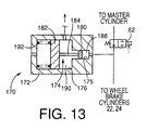
- a stroke adjusting cylinder 170 as shown in Fig. 13 is used in place of the stroke adjusting cylinder 64.
- This stroke adjusting cylinder 170 includes a cylinder housing 172, and a volume-changing piston or stroke adjusting piston 174 slidably received in the cylinder housing 172.
- the cylinder housing 172 has a stepped bore consisting of a small-diameter portion 175 and a large-diameter portion 176 having a larger diameter than the small-diameter portion 175.
- a small-diameter piston 180 and a large-diameter piston 182 are slidably received in the respective small-diameter and large-diameter portions 174, 175, and these two pistons 180, 182 are connected to each other by a connecting rod 184, so that the pistons 180, 182 are movable as a unit.
- the stroke adjusting piston 174 consists of the small-diameter and large-diameter pistons 180, 182 and the connecting rod 184.
- the small-diameter portion 175 cooperates with the small-diameter piston 180 to define a variable-volume chamber 188 communicating with the pressurizing chamber 30.
- the cylinder housing 172 cooperates with the small-diameter and large-diameter pistons 180, 182 to define a volume control chamber 190 between the two pistons 180, 182.
- the volume control chamber 190 is connected to the accumulator 72 and the master reservoir 76 through the pressure increase control valve 122 and the pressure reduction control valve 124, respectively.
- the large diameter portion 175 cooperates with the large-diameter piston 182 to define an atmospheric chamber on the side of the piston 182 remote from the volume control chamber 190.
- the atmospheric chamber is held in communication with the atmosphere.
- a sprang 192 is disposed in the atmospheric chamber to bias the stroke adjusting piston 174 in a direction of reduction of the volume of the variable-volume chamber 188.
- the stroke adjusting piston 174 While the brake pedal 10 is in the non-operated position, the stroke adjusting piston 174 is placed in its original or neutral position in which a force acting on the piston 174 based on the fluid pressure in the volume control chamber 190 is equal to the biasing force of the spring 192. As the fluid pressure in the volume control chamber 190 is increased, the stroke adjusting piston 174 is moved from the original position in the left direction as seen in Fig. 13, causing an increase in the volume of the variable-volume chamber 188, and resulting a flow of the fluid from the pressurizing chamber 30 into the variable-volume chamber 188.
- the piston 174 As the fluid pressure in the volume control chamber 190 is reduced, the piston 174 is moved from the original position in the right direction, causing a decrease in the volume of the variable-volume chamber 188, resulting in a flow of the fluid from the variable-volume chamber 188 into the pressuring chamber 30.
- the volume of the variable-volume chamber 188 is changed, so that the amount of the fluid In the pressurizing chamber 30 is accordingly changed to adjust the operating stroke of the brake pedal 10.
- the stroke adjusting device 128 and the solenoid-operated shut-off valve 62 are not essential.
- the fluid pressurizing characteristic of the master cylinder 12, that is, the relationship between the operating force F of the brake pedal 10 and the master cylinder pressure P M can be controlled as desired, without the provision of the stroke adjusting device 128.
- the fluid pressuring characteristic of the master cylinder 12 can be controlled, without the provision of the assisting device 81.
- the solenoid-operated shut-off valve 108 between the assisting pressure chamber 100 and the pressurizing chamber 32 is not essential.
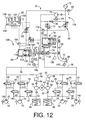
- a hydraulically operated braking system constructed according to a fourth embodiment of this invention, wherein a solenoid-operated shut-off valve 210 is provided between the master reservoir 76 and the assisting pressure chamber 100, in place of the shut-off valve 108 provided between the assisting pressure chamber 100 and the pressurizing chamber 32.
- This shut-off valve 210 is normally placed in the open position.
- the shut-off valve 210 is brought to its closed position, so that the fluid pressure in the assisting pressure chamber 100 is controlled by controlling the pressure increase and pressure reduction control valves 74, 75.
- the solenoid coil of the shut-off valve 210 is de-energized to place the shut-off valve 210 in the open position for fluid communication of the assisting pressure chamber 100 with the master reservoir 76, so that an operation of the brake pedal 10 causes the fluid to be supplied from the master reservoir 76 into the assisting pressure chamber 100, permitting the pressurizing piston 92 to be moved as the brake pedal 10 is depressed.
- the brake pedal 10 can be operated even in the event of occurrence of the first kind of abnormality of the assisting device 81.
- the fluid is returned from the pressurizing pressure chamber 100 back to the master reservoir 76 through the shut-off valve 210.
- the assisting drive force applied to the pressurizing piston 34 is zero, the fluid pressure generated in the pressurizing chambers 30, 32 is based solely on the primary drive force based on the operating force F of the brake pedal 10.
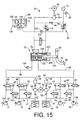
- a hydraulically operated braking system will be described by reference to Fig. 15, wherein the master cylinder 12 incorporates an assisting cylinder within a single cylinder housing.
- This arrangement has an advantage of a reduced number of parts of the braking system.
- the master cylinder 12 has a pressurizing piston 220 and a piston rod 221 which is fixed to the piston 220 and connected to the brake pedal 10.
- the piston 220 cooperates with the cylinder housing to define a pressurizing chamber 222 on one side of the piston 220 remote from the piston rod 221, and an assisting pressure chamber 224 on the other side of the piston 220.
- the assisting pressure chamber 224 is connected to the accumulator 72 through the pressure increase control valve 75, as in the first embodiment of Fig. 1.
- An increase of the fluid pressure In the assisting pressure chamber 224 will causes an increase in the force acting on the pressurizing piston 220.
- Reference numeral 225 denotes a stop which determines a fully retracted position of the pressurizing piston 220.
- the pressurizing piston 220 functions also as an assisting piston, and the distance L M between the fulcrum 96 of the brake pedal 10 and the rod 221 of the pressurizing piston 220 is equal to the distance L S between the fulcrum 96 and the rod 221 of the assisting piston 220.
- the assisting cylinder 78 may be disposed in series with the master cylinder 12 such that these cylinders 78, 12 have separate housings.
- a hydraulically operated braking system according to a sixth embodiment of this invention, wherein a check valve 230 is provided between the assisting pressure chamber 100 and the master reservoir 76.
- the check valve 230 allows a flow of the working fluid in a direction from the master reservoir 76 towards the assisting pressure chamber 100, and inhibits a flow of the fluid in the opposite direction.
- the shut-off valve 108 is opened permitting the fluid communication between the assisting pressure chamber 100 and the pressurizing chamber 32.
- the shut-off valve 108 may be held in its closed state due to an abnormality thereof such as sticking due to a foreign matter contained in the working fluid.
- the assisting pressure chamber 100 Is disconnected from both of the accumulator 72 and the master reservoir 76, and the fluid flows into and from the assisting pressure chamber 100 are inhibited.
- the check valve 230 is provided to prevent this drawback.
- the check valve 230 permits the fluid to be supplied from the master reservoir 76 to the assisting pressure chamber 100, thereby permitting an operation of the brake pedal 10 even if the shut-off valve 108 is kept closed due to its abnormality.
- the spring 104 of the pressure reduction control valve 75 has a considerably small biasing force, so that the fluid can be returned from the assisting pressure chamber 100 back to the master reservoir 76 through the pressure reduction control valve 75, without an energization of the coil 102 of the control valve 75, when the brake pedal 10 is released.
- the solenoid-operated shut-off valve 108 may be replaced by a pilot-operated switch valve which is mechanically switched from its closed state to its open state, when the fluid pressure in the accumulator 72 falls below a predetermined lower limit, that is, falls down to an abnormally low level.
- a flow restrictor device may be provided in series with the shut-off valve 108 or the pilot-operated switch valve.
- a pilot-operated switch valve 242 and a flow restrictor device 244 as indicated above are provided in series In a fluid passage 240 connecting the assisting pressure chamber 100 and the pressurizing chamber 32.
- the flow restrictor device 244 includes a check valve 246, a differential shut-off valve 248 and an orifice 250.
- the check valve 246 allows a flow of the fluid in a direction from the assisting pressure chamber 100 towards the pressurizing chamber 32, and inhibits a flow of the fluid in the opposite direction.
- the differential shut-off valve 248 allows a flow of the fluid in the direction from the pressurizing chamber 32 towards the assisting pressure chamber 100 when the fluid pressure in the pressurizing chamber 32 becomes higher than that in the assisting pressure chamber 100 by a predetermined amount P1.
- the orifice 250 is disposed in series connection with the differential shut-off valve 248. The series connection of the shut-off valve 248 and the orifice 250 is parallel with the check valve 246.
- the switch valve 242 When the fluid pressure in the accumulator 72 falls below the predetermined lower limit, the switch valve 242 is brought to the open state. However, the assisting pressure chamber 100 is disconnected from the master reservoir 32 by the flow restrictor device 244 while the fluid pressure difference of these chambers 100, 32 is smaller than the predetermined amount P1. When the brake pedal 10 is operated in this condition, the fluid is supplied from the master reservoir 76 into the assisting pressure chamber 100, thereby permitting the assisting piston 92 to be moved.
- the pressurized fluid is fed from the pressurizing chamber 32 into the assisting pressure chamber 100 through the differential shut-off valve 248, whereby the braking operating force F is boosted.
- the fluid communication of the assisting pressure chamber 100 with the pressurising chamber 32 through the switch valve 242 and the shut-off valve 248 will cause an increase in the operating stroke S of the brake pedal 10.
- the pressurizing fluid is not supplied from the pressurizing chamber 32 into the assisting pressure chamber 100 immediately after the switch valve 242 has been opened. Accordingly, the operating stroke is more or less restricted by this time delay.
- the master cylinder pressure P M changes with the operating stroke S, as indicated by one-dot chain line in the graph of Fig. 19, when the pressurizing chamber 32 and the assisting pressure chamber 100 are disconnected from each other, and as indicated by broken line in the graph of Fig. 19, when these chambers 32, 100 are connected to each other.
- the present embodiment is adapted such that the master cylinder pressure P M changes with the operating stroke S, along the one-dot chain line as long as the differential shut-off valve 248 is held in the closed state, and along the broken line after the shut-off valve 248 has been brought to the open position.
- the provision of the orifice 250 provides a delay for the braking effect to be provided when the operating speed of the brake pedal 10 is relatively high. That is, although the shut-off valve 248 is relatively quickly opened when the operating speed of the brake pedal 10 is relatively high, the rate of flow of the fluid from the pressurizing chamber 32 towards the assisting pressure chamber 100 is restricted by the orifice 250.
- the fluid is returned from the assisting pressure chamber 100 to the pressurizing chamber 32 through the switch valve 242 and the check valve 246, and then to the master reservoir 76 through the pressurizing chamber 32.
- the differential shut-off valve 248 may be a solenoid-operated shut-off valve whose opening pressure difference is controllable, like the pressure increase control valve 74.
- the predetermined amount P1 (indicated in the graph of Fig. 19) at which the curve along which the master cylinder pressure P M changes with the operating stroke S is changed from the one-dot chain line to the broken line can be changed.
- the switch valve 242 may be replaced by a mechanically operated or solenoid-operated switch valve which is brought to its open state when the fluid pressure in the pressurizing chamber 32 has become higher than that in the assisting pressure chamber 100 by a predetermined amount while the fluid pressure in the accumulator 72 is lower than the predetermined lower limit.
- the master cylinder pressure P M changes with the operating stroke S along the broken line of Fig. 19 after the chambers 32, 100 has been brought into communication with each other through the mechanically operated or solenoid-operated switch valve. It is also noted that the orifice 250 is not essential. An increase in the operating stroke S is limited since the shut-off valve 248 is not opened immediately after the switch valve 242 has been opened.
- the pump 70 and the accumulator 72 are used commonly for both of the stroke adjusting device 128 and the assisting device 81, two sets of pump and accumulator may be provided for the two devices 128, 81, respectively.
- the operating stroke S when the chambers 100, 32 are communicated with each other can be restricted by the stroke adjusting device 128.
- At least one of the assisting device 81 and the stroke adjusting device 128 includes an electric motor for activating these devices 81, 128.
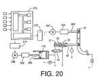
- a hydraulically operated braking system according to an eighth embodiment of this invention shown in Fig. 20 includes two electric motors 262, 268.
- the electric motor 262 is connected to an assisting rod 260 through a motion converting device 264.
- the assisting rod 260 engages the brake pedal 10.
- the electric motor 268 is connected to a volume-changing piston or stroke adjusting piston 266 through a motion converting device 269.
- the motion converting devices 264, 269 are adapted to convert rotary motions of the electric motors 262, 268 into linear motions of the assisting rod 260 and stroke adjusting piston 266, respectively.
- the electric motors 262, 268 are connected to a motor control device 270 through respective driver circuits 272, 274, so that the motors 262, 268 are controlled by the motor control device 270.
- An assisting electric drive force to be applied to the assisting rod 260 is controlled by controlling the electric motor 262, and the volume of the variable-volume chamber 116 is controlled by controlling the electric motor 268.
- the present eighth embodiment does not require the pump 70, accumulator 72, pressure increase control valves 74, 122 and pressure reduction control valves 75, 124. Accordingly, the space required for installing the braking system is reduced.
- the solenoid-operated shut-off valve 62 is closed, so that the braking pressure to be applied to the wheel brake cylinders 22, 24 can be increased by reducing the volume of the variable-volume chamber 116.
- the electric motors 262, 268 may be replaced by electric actuators each including a piezoelectric element or elements. In this case, the motion converting devices are not necessary. However, forces generated by the piezoelectric elements may be applied to the assisting rod 260 and stroke adjusting piston 266 through respective motion converting devices.
- the solenoid-operated shut-off valve 62 may be brought to its closed state when the master cylinder 12 is not normally operable to generate the fluid pressure in the pressurizing chamber 30. For instance, the shut-off valve 62 may be closed when the fluid pressure detected by the master cylinder pressure sensor 156 is lower than a predetermined lower limit.
- the rods 95, 98 of the assisting and pressurizing pistons 92, 34 engage the brake pedal 10 such that the engaging ends of the rods 95, 98 are movable relative to the brake pedal 10 in the longitudinal direction of the brake pedal 10.
- this arrangement is not essential. That is, where the rods 95, 98 are connected to the pistons 92, 34 pivotably relative to the pistons 92, 34, the rods 95, 98 are pivotable relative to the brake pedal 10 provided the rods 95, 98 engage the brake pedal 10 pivotably thereto.
- a hydraulically operated braking system constructed according to a ninth embodiment of the present invention, wherein the master cylinder and the assisting cylinder are provided in a single integral housing, in series connection with each other.
- This braking system is designed for a rear-drive vehicle wherein the rear wheels 14, 16 are drive wheels (driven by a drive power source) while the front wheels 18, 20 are driven wheels.
- the braking system of Fig. 21 includes a master cylinder 300 having two pressurizing chambers 302, 304.
- the first pressurizing chamber 302 is connected through a fluid passage 306 to the wheel brake cylinders 26, 28 for the front wheels 18, 20, while the second pressurizing chamber 304 is connected through a fluid passage 308 to the wheel brake cylinders 22, 24 for the rear wheels 14, 16.
- the solenoid-operated shut-off valves 44 are provided in the fluid passages 306, 308.
- normally-open solenoid-operated shut-off valves 312 are provided in a fluid passage connecting the wheel brake cylinders 22, 24 and the reservoir 76
- normally-closed solenoid-operated shut-off valves 316 are provided in a fluid passage 314 connecting the wheel brake cylinders 26, 28 and the reservoir 76.
- shut-off valves 312, 316 are closed to increase the fluid pressures in the wheel brake cylinders 22, 24, 26, 28, and are opened to reduce the fluid pressures in these wheel brake cylinders.
- these shut-off valves 312, 316 are opened to return the fluid from the wheel brake cylinders 22-28 to the reservoir 76.
- the normally-closed shut-off valves 316 are kept open for a predetermined time suitable for the fluid to be able to be completely returned to the reservoir 76, and are then held in the closed state.
- the solenoid coils of the shut-off valves 312, 316 are connected through respective driver circuits to both of the pressure control device 80 and an emergency control device 318.
- the shut-off valves 312, 316 are controlled by the pressure control device 80.
- the shut-off valves 312, 316 are controlled by the emergency control device 318, so that the wheel brake cylinders 22-28 can be normally activated even in the event of an electrical defect associated with the pressure control device 80.
- the master cylinder 300 has a cylinder housing 320 which houses a first pressurizing piston 322 movable relative to the cylinder housing 320, and a second pressurizing piston 324 movable to the first pressurizing piston 322.
- the first pressurizing piston 322 is operatively connected to the brake pedal 10, so that the piston 322 is moved in response to an operation of the brake pedal 10.
- the second piston 324 divides the interior space of the cylinder housing 320 into the first and second pressurizing chambers 302, 304.
- the second pressurizing piston 324 includes two cylindrical pistons 330, 332 each of which is closed at one of its opposite ends and is open at the other end.
- the cylindrical piston 330 which is remote from the first pressurizing piston 322 functions as a partition member separating the first and second pressurizing chambers 302, 304 from each other will be referred to as "a front second pressurizing piston” while the other cylindrical piston 332 will be referred to as "a rear second pressurizing piston”.
- the outer circumferential surface of the front second pressurizing piston 330 fluid-tightly and slidably engages an annular radial wall 334 formed on the inner circumferential surface of the cylinder housing 320.
- the rear second pressurizing piston 332 has two annular radial walls 336, 337 formed on its outer circumferential surface such that the annular radial walls 336, 337 are spaced apart from each other in the axial direction of the piston 332. At these annular radial walls 336, 337, the rear second pressurizing piston 332 fluid-tightly and slidably engages the inner circumferential surface of the cylinder housing 320.
- the second pressurizing chamber 304 is formed in front of the front second pressurizing piston 330 with the annular radial wall 334 fluid-tightly engaging the inner circumferential surface of the cylinder housing 320.
- a spring 338 is disposed in the second pressurizing chamber 304, to bias the front second pressurizing piston 330 in the rear direction toward the rear second pressurizing piston 332, so that the bottom wall 340 of the front second pressurizing piston 330 is held in abutting contact with an annular axial protrusion 343 formed on the bottom wall 342 of the rear second pressurizing piston 332, whereby the pistons 330, 332 are axially movable as a unit (second pressurizing piston 324).
- the fully retracted position of the second pressurizing piston 324 is determined by abutting contact of a rear open end face 346 of the rear second pressurizing piston 332 with a rear end face 347 of the cylinder housing 320.
- the first pressurizing piston 322 fluid-tightly and slidably engages the inner circumferential surface of the rear second pressurizing piston 332.
- the first pressurizing piston 322 and the rear second pressurizing piston 332 cooperate to define a fluid chamber 348 in front of the first pressurizing piston 322.
- the bottom wall 342 of the rear second pressurizing piston 332 has an orifice 350 for fluid communication between the fluid chamber 348 and an annular chamber 344 which is defined by the inner circumferential surface of the cylinder body 320, the outer circumferential surface of the second pressurizing piston 324, the annular radial walls 334, 336 and the annular axial protrusion 343.
- the orifice 350 permits the fluid pressures in the fluid chamber 348 and the annular chamber 344 to be equal to each other.
- the first pressurizing chamber 302 consists of the annular chamber 344 and the fluid chamber 348.
- the volume of the first pressurizing chamber 302 (volume of the fluid chamber 348) is reduced and the fluid pressure in the first pressurizing chamber 302 is increased, as the first pressurizing piston 322 is moved toward the second pressurizing piston 324.
- the volume of the second pressurizing chamber 304 is reduced and the fluid pressure in the second pressurizing chamber 304 is increased, as the second pressurizing piston 324 is advanced.
- the volume of the annular chamber 344 is also reduced to thereby reduce the volume of the first pressurizing chamber 302.
- a spring 352 is disposed in the fluid chamber 348, to bias the first pressurizing piston 322 in the rear direction.
- the first pressurizing piston 322 cooperates with the cylinder body 320 to define an assisting pressure chamber 360 on the side of the first pressurizing piston 322 remote from the fluid chamber 348.
- the assisting pressure chamber 360 is connected to the assisting drive force control device 109 through a fluid passage 361.
- An assisting drive force based on the fluid pressure in the assisting pressure chamber 360 acts on the first pressurizing piston 322 in the forward direction so as to boost the operating force F of the brake pedal 10.
- the first pressurizing piston 322 also functions as an assisting piston.
- the first pressurizing piston 322 has a large-diameter portion 362 slidably engaging the cylinder body 320, and rear and front axial sections of this large-diameter portion 362 are considered to be the assisting piston and the pressurizing piston, respectively.
- a normally-open solenoid-operated shut-off valve 363 is provided in the fluid passage 361.
- This shut-off valve 363 is placed in its closed state when the braking system is operated to perform a traction control of the rear drive wheels 14, 16 (by activating the wheel brake cylinders 22, 24 to control the drive forces of the rear drive wheels 14, 16 so as to prevent excessive slipping of these drive wheels, during starting of the vehicle, for example), or to perform a vehicle turning stability control (by activating a selected one or ones of the wheel brake cylinders 22-28 so as to improve the turning stability of the vehicle during turning).
- the shut-off valve 363 is held in its open state when the brake pedal 10 is operated.
- a pressurized fluid is supplied from the second pressurizing chamber 304, while inhibiting this fluid to be supplied to the assisting pressure chamber 360, during the traction control or the vehicle turning stability control.
- a stop 364 is provided in the assisting pressure chamber 360, to determine the fully retracted position of the first pressurizing piston 322.
- the first pressurizing chamber 302 and the assisting pressure chamber 370 are connected to each other through a fluid passage 370.
- a solenoid-operated shut-off valve 372 and a flow restrictor device 374 are provided in the fluid passage 370, in series with each other.
- the flow restrictor device 374 includes a differential shut-off valve 376, an orifice 377 and a check valve 378.
- the shut-off valve 372 is a normally-open valve which Is held open while the solenoid coil is in a de-energized state.
- This shut-off valve 372 is closed when the brake pedal 10 is operated, when the fluid pressures in the wheel brake cylinders 22, 24 for the drive wheels 14, 16 are increased to perform the traction control or to apply a brake to one of the drive wheels 14, 16 during the vehicle turning stability control.
- the shut-off valve 372 is held in its closed state with the solenoid coil kept de-energized, even when the brake pedal 10 is operated or the traction or vehicle turning stability control is commanded to be effected.
- the pressurized fluid in the first pressurizing chamber 302 is supplied to the assisting pressure chamber 360 through the differential shut-off valve 376, orifice 377 and shut-off valve 372.
- the second pressurizing chamber 304 and the assisting pressure chamber 370 are connected to each other through a fluid passage 380 in which a solenoid-operated shut-off valve 382 and a flow restrictor device 384 are provided.
- the shut-off valve 382 is closed when the brake pedal 10 is operated, but is held in its open state when the traction control or the vehicle turning stability control is effected.
- shut-off valve 382 is held in the open state while the above-indicated shut-off valve 372 is held in its closed state, so that the pressurized fluid controlled by the assisting drive force control device 109 is not supplied to the first pressurizing chamber 302, but is supplied to the second pressurizing chamber 304 through the shut-off valve 382 and the check valve 386.
- the shut-off valve 382 is returned to the open state, causing the pressurized fluid in the second pressurizing chamber 304 to be supplied to the assisting pressure chamber 360 through the differential shut-off valve 388, orifice 389 and shut-off valve 382.
- the operating force F of the brake pedal 10 is detected by a force sensor 390, and the fluid pressure in the assisting pressure chamber 360 is detected by an assisting pressure sensor 392, while the fluid pressure in the first pressurizing chamber 302 is detected by a master cylinder pressure sensor 394.
- the force sensor 390 is a relatively inexpensive sensor which is capable of detecting the operating force with a relatively high degree of accuracy when the operating force is relatively small, but with a relatively low degree of accuracy when the operating force is relatively large.
- the operating force of the brake petal 10 is estimated on the basis of the fluid pressures in the assisting pressure chamber 360 and the first pressurizing chamber 302.
- the force sensor 390 is adapted to detect as the operating force F a reaction force F' which is applied from the first pressurizing piston 322 to the brake pedal 10.
- L M represents the distance between the fulcrum 96 of the brake pedal 10 and the engaging end of the assisting piston 322, while L F represents the distance between the pedal pad 97 and the fulcrum 96.
- the first and second pressurizing chambers 302, 304 are connected to the reservoir 76 through respective fluid passages 398, 399, while a fluid passage 400 connected to the suction side of the pump 70 is also connected to the reservoir 76.
- the interior of the reservoir 76 is divided by partition members 401a and 401b into three fluid chambers to which the three fluid passages 398, 399 and 400 are connected, respectively, so that an abnormality of one of three hydraulic circuit systems associated with the chambers 302, 304 and pump 70 will not have an influence on the other hydraulic circuit systems.
- check valves 402a, 402b In the fluid passage 398, there are provided two check valves 402a, 402b in series with each other. These check valves 402a, 402b inhibit a flow of the fluid in a direction from the first pressurizing chamber 302 towards the reservoir 76, but permit a flow the fluid in the opposite direction. In the presence of the check valves 402a, 402b inhibiting the fluid flow from the chamber 302 towards the reservoir 76, the fluid pressure in the chamber 302 can be increased with high stability when the first pressurizing piston 322 is advanced.
- check valves 402a, 402b permitting the fluid flow from the reservoir 76 into the chamber 302 when the volume of the chamber 302 is increased, the fluid pressure in the chamber 302 is prevented from being lowered below the atmospheric pressure, when the first and second pressurizing pistons 322, 324 are retracted.
- the provision of the fluid passage 398 and check valves 402a, 402b eliminates a need of providing the pressurizing pistons 322, 324 with primary cups or inlet valves, and a need of giving the pressurizing pistons 322, 324 relatively large operating strokes for opening and closing such primary cups or inlet valves, whereby the longitudinal dimension of the master cylinder 300 can be reduced.
- two check valves 404a, 404b are provided in series with each other in the fluid passage 399 connected to the second pressurizing chamber 304.
- the cylinder housing 320 has two openings 406, 407 which are open in the respective first and second pressurizing chambers 302, 304 and to which the respective fluid passage 398, 399 are connected. These openings 406, 407 are always open in the chambers 302, 304 irrespective of the axial position of the second pressurizing piston 324 relative to the cylinder housing 320.
- the second pressurizing piston 324 consists of the front second pressurizing piston 330 whose outer circumferential surface fluid-tightly and slidably engages the annular radial wall 334 formed on the inner circumferential surface of the cylinder housing 320, and the rear second pressurizing piston 332 whose annular radial walls 336, 337 fluid-tightly and slidably engages the Inner circumferential surface of the cylinder housing 320.
- the opening 406 is positioned so as to avoid closure of the opening 406 by the annular radial wall 336.
- the fluid passage 400 and the fluid passage 361 are connected to each other through a fluid passage 410 which by-passes the pressure increase and pressure reduction control valves 74, 75.
- a fluid passage 410 which by-passes the pressure increase and pressure reduction control valves 74, 75.
- the fluid passage 410 there are provided two check valves 412, 413 which permit a fluid flow in a direction from the reservoir 76 towards the assisting pressure chamber 360, inhibit a fluid flow in the opposite direction.
- the fluid passage 410 permits the fluid to be supplied from the reservoir 76 to the assisting pressure chamber 360, to thereby prevent the fluid pressure in the chamber 360 to be lowered below the atmospheric level, when the brake pedal 10 is operated in the event of an electrical abnormality that prevents energization of the solenoid coils of the control valves 74, 75 and causes these control valves to be held in the closed state.
- a solenoid-operated shut-off valve 418 is provided between the pressure reduction control valve 75 and the reservoir 76a. This shut-off valve 418 is opened when the fluid pressure in the assisting pressure chamber 360 is reduced, that is, when the fluid is returned from the chamber 360 to the reservoir 76 through the pressure reduction control valve 75. In the other condition, the shut-oft- valve 418 is held in the closed state. The shut-off valve 418 functions to prevent a discharge flow of the fluid from the assisting pressure chamber 360 through the control valve 75, and permits the fluid to be discharged from the assisting pressure chamber 360 to the reservoir 76 when the control valve 74 is open.
- shut-off valve 418 may be considered to be a pressure reduction responsive shut-off valve which is opened when the pressure reduction control valve 75 is opened.
- the shut-off valve 418 may be positioned between the pressure reduction control valve 74 and a point of connection 419 of the pressure increase control valve 74 with the fluid passage 361.
- the ROM 132 of the pressure control device 80 stores a traction control program for performing the traction control of the drive wheels 14, 16, a vehicle turning detecting program for detecting a turning of the vehicle, a vehicle turning stability control program for performing the vehicle turning stability control, and an operating force estimating program for estimating the operating force F of the brake pedal 10, in addition to the motor control program for executing the motor control routine illustrated in the flow chart of Fig. 8, and the assisting drive force control program for controlling the fluid pressure in the assisting pressure chamber 360.
- the accelerator operation sensor 420 detects an operation of an accelerator pedal of the vehicle, and a turning of the vehicle is detected on the bases of the yaw rate of the vehicle detected by the yaw rate sensor 422 and the wheel speeds detected by the wheel speed sensors 140-146.
- the rear and front second pressurizing pistons 332, 330 are advanced against the biasing force of the spring 338, so that the volume of the annular chamber 344 is reduced, and the fluid pressure in the first pressurizing chamber 302 is accordingly increased.
- the fluid pressurized in the first pressurizing chamber 302 is supplied to the wheel brake cylinders 26, 28, while the fluid pressurized in the second pressurizing chamber 304 is supplied to the wheel brake cylinders 22, 24.
- the fluid pressure in the assisting pressure chamber 360 is controlled by controlling the pressure increase and pressure reduction control valves 74, 75, as described above with respect to the first embodiment of Fig. 1.
- shut-off valves 312, 316 are opened to return the pressurized fluid from the wheel brake cylinders 22-28 to the reservoir 76.
- the shut-off valves 312 for the rear wheels 14, 16 are held in the open state, while the shut-off valves 316 for the front wheels 18, 20 are held in the open state for a predetermined time and are then restored to the closed state.
- the pressurized fluid in the assisting pressure chamber 360 is returned partly to the reservoir 76 through the normally-open pressure reduction control valve 75, partly to the first pressurizing chamber 302 through the opened shut-off valve 372 and the check valve 378, and partly to the second pressurizing chamber 304 through the opened shut-off valve 382 and the check valve 386.
- the fluid is supplied from the reservoir 76 to the chambers 302, 304 through the fluid passages 398, 399, so that the fluid pressures in the chambers 302, 304 are prevented from being lowered below the atmospheric level.
- the brake pedal 10 is operated at a relatively high speed so as to reduce the volume of the fluid chamber 348
- the fluid pressure in the fluid chamber 348 is rapidly increased due to a fluid flow restricting function of the orifice 350, so that a relatively large fluid pressure difference is generated between the fluid chamber 348 and the annular chamber 346.
- the second pressurising piston 324 is advanced by this fluid pressure difference, and the volumes of the first and second pressurizing chambers 302, 304 are reduced so as to rapidly increase the fluid pressures in these chambers 302, 304 and the fluid pressures in the wheel brake cylinders 22-28.
- This arrangement is effective to reduce a delay in the braking effect in an initial portion of the operation of the brake pedal 10 at a relatively high speed.
- the operating force F' as detected by the force sensor 390 is increased, and the fluid pressure in the assisting pressure chamber 360 is controlled so as to increase with the detected operating force F', so that the fluid pressure in the fluid chamber 348 is further increased to increase the fluid pressure in the wheel brake cylinders 22-28.
- the shut-off valves 382 When the amount of slip of the drive wheels 22, 24 has become excessively large with respect to the friction coefficient of the road surface, that is, when the predetermined condition for initiating the traction control of the drive wheels 22, 24 is satisfied, the shut-off valves 382 is held in the open state, and the shut-off valves 372 and 363 are closed.
- the pressurized fluid whose pressure is controlled by the assisting drive force control device 109 is supplied to the second pressurizing chamber 304, but is not supplied to the assisting pressure chamber 360 and the first pressurising chamber 302.
- the fluid pressure in the wheel brake cylinders 22, 24 is controlled by controlling the shut-off valves 44, 312, so as to hold the slipping amount of the drive wheels 14, 16 within an optimum range.
- the second pressurising piston 324 is placed in its fully retracted position, so that the pressurized fluid supplied to the second pressurizing chamber 304 will not causes a retracting movement of the second pressurizing piston 324.
- the fluid pressure in the second pressurizing chamber 304 can be increased while the volume of the first pressurizing chamber 302 is held constant. In other words, only the fluid pressure in the wheel brake cylinders 22, 24 for the drive wheels 14, 16 can be increased, without increasing the fluid pressure in the wheel brake cylinders 26, 28 for the driven wheels 18, 20.
- the first pressurizing piston 322 is permitted to be advanced while the second pressurizing piston 324 is placed in the fully retracted position.
- the fluid pressure in the first pressurizing chamber 302 can be increased immediately after an operation of the brake pedal 10 during the traction control, so that the driven wheels 18, 20 can also be braked with a high response to the operation of the brake pedal 10 during the traction control.
- the operation of the brake pedal 10 during the traction control causes the shut-off valve 363 to be opened to supply the pressurized fluid from the assisting drive force control device 108 to the assisting pressure chamber 360.
- An increase in the operating stroke of the brake pedal 10 operated during the traction control can be restricted by closing the shut-off valve 382.
- the vehicle turning stability control is initiated to remove this tendency.
- the vehicle turning stability control is effected to generate a difference between the fluid pressures in the wheel brake cylinders 22, 24 for the right and left drive wheels 14, 16, so as to give a yaw moment to the vehicle for thereby eliminating the excessive spinning or drift-out tendency of the turning vehicle.
- the shut-off valves 372, 373 are closed while the shut-off valve 382 is held open, as in the traction control.
- the fluid pressures in the wheel brake cylinders 22, 23 for the drive wheels 14, 16 are controlled independently of each other, by controlling the shut-off valves 44, 312.
- the solenoid-operated shut-off valves 363, 372, 382 are opened, and the pressurized fluid is supplied from the accumulator 72 to the assisting pressure chamber 360 and the first and second pressurizing chambers 302, 304.
- the pressurized fluid in the second pressurizing chamber 304 is supplied to the assisting pressure chamber 360 through the differential shut-off valve 388, orifice 389 and shut-off valve 382.
- the fluid pressures in the wheel brake cylinders 22-28 can be increased while restricting an increase in the operating stroke of the brake pedal 10.
- the shut-off valve 418 is in the closed state, the pressurized fluid in the assisting pressure chamber 360 is prevented from being discharged into the reservoir 76 through the pressure reduction control valve 74.
- the provision of the orifices 377, 389 is effective to reduce a delay of the braking effect when the operating speed of the brake pedal 10 is relatively high.
- the solenoid-operated shut-off valves 312, 316 is controlled by the emergency control device 318, so that the braking system can be operated.
- the assisting device 81 provides a second pressurizing chamber pressurizing device for pressurizing the fluid in the second pressurizing chamber 304, and the rear open end face 346 of the second pressurizing piston 324 and the rear end face of the cylinder housing 320 cooperate to provide a volume reduction preventing device for preventing reduction of the volume of the first pressurizing chamber 302 when the fluid pressure in the second pressurizing chamber 304 is increased by the second pressurizing chamber pressurizing device.
- the assisting pressure sensor 392, master cylinder pressure sensor 394 and a portion of the pressure control device 80 assigned to estimate the operating force F' of the brake pedal 10 on the basis of the outputs of these pressure sensors 392, 394 cooperate to provide a brake operating force estimating device for estimating the operating force F' of the brake pedal 10.
- the shut-off valves 312 for the rear drive wheels 14, 16 are normally open, while the shut-off valves 316 for the front driven wheels 18, 20 are normally closed.
- the shut-off valves 312 are normally closed while the shut-off valves 316 are normally open.
- the shut-off valve 363 is not essential, since the fluid pressurized in the first pressurizing chamber 302 as a result of an advancing movement of the first pressurizing piston 322 by the pressurized fluid supplied to the assisting pressure chamber 360 during the traction control is returned to the reservoir 76 through the normally open shut-off valves 316, so that the wheel brake cylinders 26, 28 are not activated during the traction control.
- the configuration of the second pressurizing piston 324 is not limited to the details of the illustrated ninth embodiment.
- the front and rear second pressurizing pistons 330, 332 may be formed integrally with each other, or the front second pressurizing piston 330 may take the form of a circular disc.
- the fully retracted position of the second pressurizing piston 324 need not be defined by the rear end of the cylinder housing 320.
- the first and second pressurizing pistons 322, 324 may be disposed in series, and may have the same pressure-receiving surface areas. It is needless to say that the master cylinder and the assisting cylinder may be provided as separate units.
- the stroke adjusting device 128 may be provided in the present braking system of Fig. 21.
- FIG. 22 showing a hydraulically operated braking system constructed according to a tenth embodiment of this invention.
- the braking system of Fig. 22 uses a master cylinder 500 including a cylinder body 502 in which there are fluid-tightly and slidably received a first and a second pressurizing piston 504, 506.
- the cylinder body 502 and the two pressurizing pistons 504, 506 define a first and a second pressurizing piston 508, 510 in front of the two pistons 504, 506, respectively.
- the cylinder body 502 and the first pressurizing piston 504 cooperate to define an assisting pressure chamber 512 on the side of the piston 504 remote from the first pressurizing chamber 508.
- the first pressurizing piston 504 also functions as an assisting piston.
- the cylinder housing 502 is provided with a pair of primary cups 514 and a pair of primary cups 516, and has a port 520 formed between the primary cups 514.
- the second pressurising chamber 510 is connected to the reservoir 76 through the port 520 and a fluid passage 522.
- the second pressurizing piston 506 has a communication hole 524 open in the second pressurizing chamber 510.
- the communication hole 524 is positioned such that the second pressurizing chamber 510 communicates with the port 520 through the hole 524 when the second pressurizing piston 506 is placed in the original or fully retracted position with the brake pedal 10 placed in the non-operated position.
- the communication hole 524 is closed by the cylinder housing 502 and is disconnected from the port 520, so that the fluid pressure in the chamber 510 can be increased when the brake pedal 10 is operated.
- the second pressurizing piston 506 When the brake pedal 10 is released, the second pressurizing piston 506 is returned to the fully retracted position in which the communication hole 520 communicates with the port 520, to permit the pressurized fluid to be discharged from the second pressurizing chamber 520 into the reservoir 76 through the fluid passage 522.
- the fluid As the volumes of the first and second pressurizing chambers 508, 510 are increased, the fluid is supplied from the reservoir 76 through the fluid passage 522 into the chambers 508, 510 with elastic deformation of the primary cups 514, so that the fluid pressures in the chambers 508, 510 are prevented from being lowered below the atmospheric level.
- the first pressurizing chamber 508 and the assisting pressure chamber 512 are fluid-tightly separated from each other by the pair of primary cups 516.
- the master cylinder 500 of the present embodiment is not a piston type cylinder, but is a Girling or plunger type cylinder using the primary cups 514, 516 held by the cylinder housing 502.
- a spring 517 is disposed in the second pressurizing chamber 510, to bias the second pressuring piston 506 towards the fully retracted position, while a spring 518 is disposed in the first pressurizing chamber 508, to bias the first pressuring piston 504 towards the fully retracted position via retainers 519a, 519b.
- the cylinder housing 502 has ports 526, 530 and 534 in addition to the port 520 indicated above.
- the port 526 is open to the second pressurizing chamber 310 and is connected to a fluid passage 528, which is connected to a fluid passage 536 connected to the port 534 open to the assisting pressure chamber 512.
- the second pressurizing chamber 510 is connected to the assisting pressure chamber 512 through the port 526, fluid passages 528, 536 and port 534.
- the port 530 is open to the first pressurizing chamber 508 and is connected to a fluid passage 531 which is connected to the fluid passage 528.
- the first and second pressurizing chambers 508, 510 and the assisting pressure chamber 512 are connected to each other through the fluid passages 528, 530, 536.
- the fluid passage 531 is connected also to a fluid passage 532 connected to the reservoir 76.
- a check valve 533 is provided in the fluid passage 532. This check valve 533 allows a flow of the fluid in a direction from the reservoir 76 towards the first pressurizing chamber 508, but inhibits a flow of the fluid in the opposite direction.
- the assisting pressure chamber 512 is connected to an assisting drive force control device 538 through the port 534 and the fluid passage 536.
- a normally-open solenoid-operated shut-off valve 542 is provided in a portion of the fluid passage 528 between the second pressurizing chamber 510 and a point of connection to the fluid passage 531 connected to the first pressurizing chamber 508.
- a normally-open solenoid-operated shut-off valve 546 and a flow restrictor device 547 are provided in a portion of the fluid passage 528 between the above-indicated point of connection and the fluid passage 536 connected to the assisting pressure chamber 512.
- the flow restrictor device 547 includes a differential shut-off valve 548 and a check valve 550.
- the assisting drive force control device 538 includes the pressure increase control valve 74, pressure reduction control valve 74, pump 70 and accumulator 72.
- the flow restirctor device 538 further includes two normally-closed solenoid-operated shut-off valves 560, 562.
- the shut-off valve 560 which functions as an emergency closure valve, is disposed between the assisting pressure chamber 512 and the solenoid-operated pressure control valve device 82 which includes the pressure increase and pressure reduction control valves 74, 75. While the brake pedal 10 is in operation, the shut-off valve 560 is held in the open state if the solenoid-operated pressure control valve device 82 is normal, but is restored to the closed state if the valve device 82 becomes abnormal.
- the shut-off valve 560 placed in the closed state prevents a continuous discharge flow of the pressurized fluid from the assisting pressure chamber 512 into the reservoir 76 through the pressure reduction control valve 75, and a continuous supply flow of the pressurized fluid from the accumulator 72 into the assisting pressure chamber 512 through the pressure increase control valve 74.
- the assisting pressure chamber 512 is connected to the reservoir 76 through a reservoir passage 564 which by-passes the solenoid-operated pressure control valve device 82 and the shut-off valve 560.
- the check valves 412, 412 are provided in the reservoir passage 564.
- the solenoid-operated shut-off valve 562 which functions as an emergency high-pressure source communicating device, is disposed in a by-pass passage 570 which connects the assisting pressure chamber 512 and the accumulator 72, while by-passing the solenoid-operated pressure control valve device 82 and the shut-off valve 560.
- the shut-off valve 562 is normally held in the closed state, but is brought to the open state if at least one of the pressure increase and pressure reduction control valves 74, 75 cannot be opened while the electrical system is normal.
- the shut-off valve 562 placed in the open state permits the pressurized fluid to be supplied from the accumulator 72 to the assisting pressure chamber 512.
- the shut-off valve 562 may be disposed in a by-pass passage which connects the delivery side of the pump 70 and the assisting pressure chamber 512 while by-passing the solenoid-operated pressure control valve device 82 and the shut-off valve 560.
- the shut-off valve 562 is opened in the event of occurrence of an abnormality of the pressure control valve device 82 or the shut-off valve 560, so that the fluid delivered from the pump 70 is supplied to the assisting pressure chamber 512.
- the control valves 74, 75 and the solenoid-operated shut-off valves 542, 546, 560, 562 are controlled as indicated in the table of Fig. 23.
- the pressure increase and pressure reduction control valves 74, 75 are controlled to control the fluid pressure in the assisting pressure chamber 512, in the same manner as described with respect to the embodiment of Fig. 1, and the shut-off valve 560 is held in the open state while the shut-off valve 546, is held in the closed state.
- the shut-off valve 542 When the wheel braking pressures are increased, the shut-off valve 542 is closed, and the pressurized fluid from the accumulator 72 is controlled by the pressure increase control valve 74 and supplied to the assisting pressure chamber 512 through the shut-off valve 560.
- the shut-off valve 542 When the wheel braking pressures are reduced, the shut-off valve 542 is restored to the open state, and the pressurized fluid in the assisting pressure chamber 512 is returned to the reservoir 76 through the pressure reduction control valve 75, while the pressurized fluid in the first pressurizing chamber 508 is returned to the reservoir 76 through the shut-off valve 542 and the second pressurizing chamber 510.
- the pressure reduction control valve 75 is held in the fully open state for a predetermined time with the maximum electric current being applied to the solenoid coil.
- the fluid is supplied from the reservoir 76 into the first pressurising chamber 508 through the fluid passages 532, 531, so that the fluid pressure in the chamber 508 is prevented from being lowered below the atmospheric level.
- the pressure increase and pressure reduction control valves 74, 75 are controlled to control the fluid pressure in the assisting pressure chamber 512, as in the normal braking operation.
- the shut-off valve 542 is closed, and the shut-off valve 546 is opened, so that the pressurized fluid whose pressure is controlled by the assisting drive force control device 538 is supplied to not only the assisting pressure chamber 512 but also the first pressurizing chamber 508.
- the pressurized fluid in the assisting pressure chamber 512 is returned to the reservoir 76 partly through the pressure reduction control valve 76, and partly through the shut-off valve 546, check valve 550, shut-off valve 542 and second pressurizing chamber 510. It is noted that the shut-off valve 542 may be opened when the wheel braking pressures are increased. In this case, the pressurized fluid whose pressure is controlled by the assisting drive force control device 538 is also supplied to the second pressurizing chamber 510.
- the differential shut-off valve 548 When the fluid pressure in the first and second pressurizing chambers 508, 510 has become higher than that in the assisting pressure chamber 512 by the opening pressure difference of the differential shut-off valve 548 or more, the differential shut-off valve 548 is opened, so that the pressurized fluid is supplied from the pressurizing chambers 508, 510 to the assisting pressure chamber 512, whereby the wheel braking pressures are increased.
- the shut-off valve 560 is returned to the closed state, to prevent a continuous discharge flow of the fluid from the assisting pressure chamber 512 through the pressure reduction control valve 75, and a continuous supply flow of the fluid from the accumulator 72 into the assisting pressure chamber 512 through the pressure increase control valve 74.
- shut-off valve 560 in the closed state prevents or minimizes a variation in the fluid pressure in the chamber 512.
- the fluid is fed from the assisting pressure chamber 512 to the second pressurizing chamber 510 through the shut-off valve 546, check valve 550 and shut-off valve 542, and is returned to the reservoir 76.
- the shut-off valve 562 is opened.
- the control valve 74 or the shut-off valve 560 cannot be opened due to sticking of a valve member due to a foreign matter contained in the fluid.
- the shut-off valve 562 is opened to permit the pressurized fluid to be supplied from the accumulator 72 to the chamber 512 through the by-pass passage 570, for increasing the wheel braking pressures.
- the abnormality of at least one of the valves 74, 560 can be detected if the fluid pressure in the assisting pressure chamber 512 as detected by the assisting pressure sensor 392 is lower than the predetermined lower limit even when the valves 74, 560 are commanded to be open.
- the above abnormality may also be detected if the actual value of the fluid pressure in the assisting pressure chamber 512 as detected by the sensor 392 is lower than the desired or target value by more than a predetermined value, and if the absolute value of the fluid pressure difference is not reduced.
- the shut-off valves 542 and 546 as well as the shut-off valve 562 may be opened.
- the shut-off valve 562 may be closed if at least one of the pressure increase and pressure reduction control valves 74, 75 cannot be closed while the electrical system is normal.
- This abnormality of the pressure increase control valve 74 can be detected if the detected fluid pressure in the assisting pressure chamber 512 is higher than a predetermined upper limit even when the pressure increase control valve 74 is commanded to be closed.
- the abnormality can also be detected if the detected fluid pressure in the assisting pressure chamber 512 is higher than the desired or target value by more than a predetermined value, and if the absolute value of this pressure difference is increasing.
- the abnormality of the pressure reduction control valve 75 can be detected.
- the shut-off valve 562 placed in the closed state prevents an abrupt variation of the fluid pressure in the assisting pressure chamber 512 in the event of occurrence of the abnormality of at least one of the control valves 74, 75.
- the shut-off valve 562 and the by-pass passage 570 are not essential, since an abnormality of the solenoid-operated pressure control valve device 82 can be dealt with in the same manner as in the event of an electrical abnormality described above. Further, the shut-off valve 560 is not essential, since the amount of fluid pressure variation in the assisting fluid chamber 512 due to the fluid leakage through the solenoid-operated pressure control valve device 82 is small where the fluid leakage is not serious. Further, the fluid passage 532 may be connected to a portion of the fluid passage 528 between the check valve 550 and the shut-off valve 546, rather than to the fluid passage 531. In this case, the reservoir 76 and the first pressurizing chamber 508 are connected to each other through the fluid passages 532, 528 and the two check valves 533, 550.
- the cylinder housing 502 may have a port which is formed between the primary cups 516, to connect the first pressurizing chamber 508 to the reservoir 76 through a fluid passage connected to that port.
- the first pressurising piston 504 has a communication hole communicating with the first pressurizing chamber 508 and the above-indicated port when the piston 504 is in the fully retracted position.
- the fluid is supplied from the reservoir 76 to the first pressurising chamber 508 with elastic deformation of the primary cups 516, and the fluid is returned from the chamber 508 to the reservoir 76 through the above-indicated communication hole, port and fluid-passage when the brake pedal 10 is released. Accordingly, it is not necessary to open the shut-off valve 542 when the brake pedal 10 is released to reduce the wheel braking pressures.
- FIG. 24 there is illustrated an example of the above arrangement according to an eleventh embodiment of this invention.
- This embodiment uses a master cylinder 600 wherein the cylinder housing 502 has a port 602 formed between the pair of primary cups 516.
- the port 602 is connected to a fluid passage 604, which is connected to the reservoir 76.
- the first pressurising piston 504 has a communication hole 606 which is open to the first pressurizing chamber 508 and which communicates with the port 602 when the piston 504 is in the fully retracted position of fig. 24. Accordingly, the fluid is returned from the first pressurizing chamber 508 to the reservoir 76 through the communication hole 606, port 602 and fluid passage 604 when the piston 504 is returned to its fully retracted position.
- a normally-open solenoid-operated shut-off valve 607 is provided in the fluid passage 604. This shut-off valve 607 is closed when the fluid pressure in the assisting pressure chamber 512 is increased while the brake pedal 10 is in the non-operated position.
- the first pressurizing chamber 508 is connected to the assisting pressure chamber 512 through a fluid passage 608 in which a normally-closed solenoid-operated shut-off valve 610 is disposed.
- a flow restrictor device is not provided in the fluid passage 608.
- the present braking system has an assisting drive force control device 612 which includes an emergency high-pressure source communication device 616 as well as the pump 70, solenoid-operated pressure control valve device 82 and shut-off valves 560.
- the emergency high-pressure source communicating device 616 includes a regulator 614 and a change valve 615.
- the regulator 614 is provided in a fluid passage 618 which connects the accumulator 62 and the assisting pressure chamber 512 while by-passing the solenoid-operated pressure control valve device 82 and the shut-off valve 560.
- the regulator 614 is connected to the change valve 615, reservoir 76 and accumulator 72.
- the regulator 614 is operated on the basis of the fluid pressure in the first pressurizing chamber 508, to supply the fluid from the reservoir 76 to the change valve 615, or supply the pressurized fluid from the accumulator 72 to the change valve 615.
- the change valve 615 is connected to the fluid passages 618, 536, and to the port 534 communicating with the assisting pressure chamber 512.
- the change valve 615 functions to apply to the assisting pressure chamber 512 the fluid pressure as controlled by the regulator 614 or the fluid pressure as controlled by the solenoid-operated pressure control valve device 82 (as applied to the first pressurizing chamber 508).
- the regulator 614 includes a valve member 620, a valve seat 622, and a drive member 624. These elements 620, 622, 624 cooperate with the valve housing to define a first fluid chamber 626, a second fluid chamber 628 and a third fluid chamber 630.
- the first fluid chamber 626 is connected to the accumulator 72 through a solenoid-operated shut-off valve 632, and the second fluid chamber 628 is connected to the change valve 615, while the third fluid chamber 630 is connected to the first pressurising chamber 508.
- Pa, Pc, and P M represent the fluid pressures in the first, second and third fluid chambers 626, 628, 630, respectively, that is, the fluid pressure in the accumulator 72, the fluid pressure to be applied to the change valve 615, and the fluid pressure in the first pressurizing chamber 508 (master cylinder pressure), respectively
- S 1 , S 2 and S 3 represent the cross sectional area of the small-diameter portion of the valve member 624, the cross sectional area of a communication passage 642 between the first and second fluid chambers 626, 628, and the cross sectional area of the large-diameter portion of the drive member 624. It is noted that the biasing forces of the springs 636, 638 are ignored in the above inequality.
- the second fluid chamber 628 is disconnected from the reservoir 76, and is communicated with the first fluid chamber 626, so that the pressurized fluid of the accumulator 72 is supplied to the change valve 615.
- the fluid pressure in the assisting pressure chamber 512 (the fluid pressure to be applied to the change valve 615) is controlled depending upon the fluid pressure in the first pressurizing chamber 508.
- the change valve 615 has a first port 650 communicating with the assisting pressure chamber 512, a second port 652 connected to the regulator 614, a third port 654 connected to the fluid passage 536 (connected to the solenoid-operated pressure control valve device 82 and the first pressurizing chamber 508), and a spool which is moved such that the first port 650 is connected to one of the second and third ports 652, 654 whole fluid pressure is higher, and is disconnected to the other port 642, 654 whose fluid pressure is lower.
- the spool is placed in a neutral position in which the first port 650 is connected to both of the second and third ports 652, 654.
- the fluid pressure controlled by the regulator 614 is applied to the assisting pressure chamber 512.
- the hydraulically operated braking system constructed as described above is operated as indicated in the table of Fig. 26.
- the regulator 614 When the brake pedal 10 is in the non-operated position, the regulator 614 is placed in the original position of Fig. 24, and the spool of the change valve 615 is placed in its neutral position.
- the fluid When the brake pedal 10 is depressed, the fluid is supplied from the reservoir 76 to the assisting pressure chamber 512 through the regulator 614, change valve 615, or alternatively through the check valves 412, 413 and the change valve 615.
- the fluid pressure in the assisting pressure chamber 512 is prevented from being lowered below the atmospheric level.
- the pressure increase and pressure reduction control valves 74, 75 are controlled as described above with the tenth embodiment of Fig. 22.
- the shut-off valve 632 is held in the closed state, so that the pressurized fluid of the accumulator 72 is not supplied to the regulator 614.
- the change valve 615 is is held in a state in which the first port 6450 is connected to the third port 654, so that the assisting pressure chamber 512 is communicated with the solenoid-operated pressure control valve device 82.
- the fluid pressure controlled by the valve device 82 is applied to the assisting pressure chamber 512.
- the pressurized fluid is returned from the assisting pressure chamber 512 to the reservoir 76 through the pressure reduction control valve 75. Since the shut-off valve 607 is placed in the open state, the pressurized fluid in the first pressurizing chamber 508 is returned to the reservoir 76 through the fluid passage 704, while the pressurized fluid in the second pressurizing chamber 510 is returned to the reservoir 76 through the fluid passage 522.
- the control valves 74, 75 are controlled to control the wheel braking pressures in the same manner as in the normal braking operation.
- the shut-off valve 610 is opened in the automatic braking operation, the fluid pressure controlled by the pressure control valve device 82 is applied to not only the assisting pressure chamber 512 but also the first pressurizing chamber 508.
- the shut-off valve 607 is closed, so that the pressurized fluid in the first pressurizing chamber 508 is prevented from being returned to the reservoir 76, and the fluid pressure in the first pressurizing chamber 508 can be increased.
- the shut-off valve 607 is returned to the open state, to return the pressurized fluid from the first pressurizing chamber 508 to the reservoir 76 through the fluid passage 604.
- the fluid pressure controlled by the regulator 614 is applied to the second port 652 of the change valve 615, and the regulator 615 is operated to connect the regulator 614 to the assisting pressure chamber 512, so that the fluid pressure controlled by the regulator 614 is applied to the assisting pressure chamber 512.
- the fluid pressure in the assisting pressure chamber 512 can be increased to a level corresponding to the operating force F of the brake pedal 10, by utilizing the fluid pressure in the accumulator 72, since the pressure in the accumulator 72 will not be lowered immediately after the occurrence of the electrical abnormality.
- the pressurized fluid in the assisting pressure chamber 512 is returned to the reservoir 76 through the regulator 614.
- shut-off valves 632, 610 are opened. Since the fluid pressure in the accumulator 72 is relatively low, the fluid pressure applied to the change valve 615 through the opened shut-off valve 632 and the regulator 614 is not so high, even when the fluid pressure in the first pressurizing chamber 508 is increased by depression of the brake pedal 10. On the other hand, the fluid pressure in the first pressurising chamber 508 is applied to the third port 654 of the change valve 615 through the open shut-off valve 610, so that the change valve 615 is operated to connect the first port 650 to the third port 654.
- the fluid pressure in the first pressurizing chamber 508 is applied to the assisting pressure chamber 512, whereby the wheel braking pressures can be increased.
- the fluid in the assisting pressure chamber 512 is returned to the reservoir 76 through the shut-off valve 610 and the first pressurizing chamber 508.
- the present braking system is arranged such that the regulator 614 is operated to control the fluid pressure in the assisting pressure chamber 512 to a level depending upon the fluid pressure in the first pressurizing chamber 508, even in the event of occurrence of an electrical abnormality of the braking system.
- control of the control valves 74, 75 and shut-off valves 560, 607, 610, 632 is not limited to that of Fig. 26, which is provided by way of example only.
- the master cylinder 600 is not limited to the Girling type, but may be of a type in which primary cups are provided on the pistons 504, 506.
- the shut-off valve 632 is not essential, and may be eliminated provided the first fluid chamber 626 of the regulator 614 is held in communication with the accumulator 72.
- the change valve 615 is operated to connect the first port 650 to one of the second and third ports 652, 653 at which the fluid pressure is higher, so that the higher fluid pressure is applied to the assisting Pressure chamber 512.
- the regulator 614 When the brake pedal 10 is released, and the fluid pressure in the first pressurizing chamber 508 is reduced, the regulator 614 is operated to connect the change valve 615 to the reservoir 76, so that the pressurized fluid is returned from the assisting pressure chamber 512 to the reservoir 76 through the change valve 615 and the regulator 614.
Landscapes
- Engineering & Computer Science (AREA)
- Physics & Mathematics (AREA)
- Transportation (AREA)
- Mechanical Engineering (AREA)
- Fluid Mechanics (AREA)
- Electromagnetism (AREA)
- Braking Systems And Boosters (AREA)
- Regulating Braking Force (AREA)
- Valves And Accessory Devices For Braking Systems (AREA)
Applications Claiming Priority (6)
| Application Number | Priority Date | Filing Date | Title |
|---|---|---|---|
| JP10751798 | 1998-04-17 | ||
| JP10751798 | 1998-04-17 | ||
| JP32024798 | 1998-11-11 | ||
| JP32024798 | 1998-11-11 | ||
| JP36457598A JP3496549B2 (ja) | 1998-04-17 | 1998-12-22 | 液圧ブレーキ装置 |
| JP36457598 | 1998-12-22 |
Publications (3)
| Publication Number | Publication Date |
|---|---|
| EP0950593A2 true EP0950593A2 (de) | 1999-10-20 |
| EP0950593A3 EP0950593A3 (de) | 2001-05-09 |
| EP0950593B1 EP0950593B1 (de) | 2003-10-29 |
Family
ID=27310999
Family Applications (1)
| Application Number | Title | Priority Date | Filing Date |
|---|---|---|---|
| EP99106961A Expired - Lifetime EP0950593B1 (de) | 1998-04-17 | 1999-04-08 | Hydraulisches Bremssystem mit einem druckunterstüzten Bremszylinderkolben |
Country Status (5)
| Country | Link |
|---|---|
| US (1) | US6945610B1 (de) |
| EP (1) | EP0950593B1 (de) |
| JP (1) | JP3496549B2 (de) |
| KR (1) | KR100326820B1 (de) |
| DE (1) | DE69912344T8 (de) |
Cited By (3)
| Publication number | Priority date | Publication date | Assignee | Title |
|---|---|---|---|---|
| US7290841B2 (en) * | 2000-08-16 | 2007-11-06 | Toyota Jidosha Kabushiki Kaisha | Hydraulic braking system including power-operated pressure source device, and device for controlling pressure output of the pressure source device |
| EP1975023A3 (de) * | 2007-03-30 | 2010-11-10 | Nissin Kogyo Co., Ltd. | Fahrzeugbremsvorrichtung |
| CN107117152A (zh) * | 2017-05-12 | 2017-09-01 | 吉林东光奥威汽车制动系统有限公司 | 一种汽车线控制动系统用电动泵 |
Families Citing this family (31)
| Publication number | Priority date | Publication date | Assignee | Title |
|---|---|---|---|---|
| US6604795B2 (en) * | 2000-12-28 | 2003-08-12 | Toyota Jidosha Kabushiki Kaisha | Braking system including high-pressure source between master cylinder and brake cylinder |
| US6953229B2 (en) | 2000-12-28 | 2005-10-11 | Toyota Jidosha Kabushiki Kaisha | Hydraulic braking system and method with flow control device |
| DE10318850A1 (de) * | 2003-04-25 | 2004-11-18 | Lucas Automotive Gmbh | Bremsanlage für ein Kraftfahrzeug |
| JP4670349B2 (ja) * | 2004-03-10 | 2011-04-13 | 株式会社アドヴィックス | 車両用制動装置 |
| JP4622328B2 (ja) | 2004-06-16 | 2011-02-02 | トヨタ自動車株式会社 | フィルアップ機能付マスタシリンダ |
| KR100954555B1 (ko) | 2004-11-23 | 2010-04-23 | 주식회사 만도 | 피에조 액추에이터 장착 전자제어식 브레이크 시스템 |
| US7395667B2 (en) * | 2006-04-28 | 2008-07-08 | Arnold Jeffrey T | Electrically driven power brake booster |
| JP5103924B2 (ja) * | 2007-02-09 | 2012-12-19 | 株式会社アドヴィックス | 車両の運動制御装置 |
| JP5123543B2 (ja) * | 2007-03-27 | 2013-01-23 | 本田技研工業株式会社 | ブレーキ装置 |
| JP4974766B2 (ja) * | 2007-05-30 | 2012-07-11 | 本田技研工業株式会社 | 車両用ブレーキ液圧制御装置 |
| JP5066004B2 (ja) * | 2008-06-06 | 2012-11-07 | 日立オートモティブシステムズ株式会社 | ブレーキシステム |
| JP5211921B2 (ja) * | 2008-07-31 | 2013-06-12 | 株式会社アドヴィックス | 制動力保持制御装置 |
| DE102010042990A1 (de) * | 2010-10-27 | 2012-05-03 | Robert Bosch Gmbh | Bremssystem für ein Fahrzeug und Verfahren zum Betreiben eines Bremssystems eines Fahrzeugs |
| DE102011080404B4 (de) * | 2011-08-04 | 2024-09-26 | Robert Bosch Gmbh | Verfahren zum Festlegen eines Funktionszustands eines Druckaufbauventils und Funktionsüberwachungsvorrichtung für ein Druckaufbauventil einer hydraulischen Bremskraftverstärkervorrichtung |
| CN102410375B (zh) * | 2011-08-23 | 2014-08-20 | 中国北方车辆研究所 | 一种两栖车辆水上密封装置 |
| US20150158476A1 (en) * | 2012-08-31 | 2015-06-11 | Toyota Jidosha Kabushiki Kaisha | Vehicle brake apparatus |
| DE112012007142T5 (de) * | 2012-11-16 | 2015-08-13 | Toyota Jidosha Kabushiki Kaisha | Fahrzeugbremsregelungs- bzw. -Steuerungsvorrichtung |
| JP6358626B2 (ja) * | 2013-03-29 | 2018-07-18 | ヴィオニア日信ブレーキシステムジャパン株式会社 | 車両用ブレーキ液圧制御装置 |
| US20150260247A1 (en) | 2014-03-11 | 2015-09-17 | Caterpillar Inc. | Braking system |
| US9707950B2 (en) * | 2014-05-16 | 2017-07-18 | Bayerische Motoren Werke Aktiengesellschaft | System and method for measurement and evaluation of brake pedal performance |
| CN106458167B (zh) * | 2014-05-20 | 2021-04-27 | 爱皮加特股份公司 | 用于车辆制动器的操纵系统和用于运行该操纵系统的方法 |
| DE102014117727A1 (de) * | 2014-12-02 | 2016-06-02 | Ipgate Ag | Betätigungsanlage für zumindest eine hydraulisch betätigbare Einrichtung, insbesondere Fahrzeugbremse |
| US10392977B2 (en) | 2016-02-11 | 2019-08-27 | Slw Automotive Inc. | Automotive lubricant pumping system with two piece relief valve |
| JP6512148B2 (ja) * | 2016-03-25 | 2019-05-15 | 株式会社アドヴィックス | 車両用制動装置 |
| ITUA20162677A1 (it) * | 2016-04-18 | 2017-10-18 | Freni Brembo Spa | Impianto frenante a controllo automatico per veicoli |
| JP7088680B2 (ja) * | 2018-01-24 | 2022-06-21 | 株式会社シマノ | 制動制御装置および制動システム |
| JP7167740B2 (ja) | 2019-01-31 | 2022-11-09 | 株式会社豊田自動織機 | ブレーキシステム |
| KR102810110B1 (ko) * | 2020-03-26 | 2025-05-20 | 에이치엘만도 주식회사 | 전자식 브레이크 시스템 |
| KR102847248B1 (ko) * | 2020-03-26 | 2025-08-18 | 에이치엘만도 주식회사 | 전자식 브레이크 시스템 |
| KR102416289B1 (ko) * | 2019-04-18 | 2022-07-05 | 현대모비스 주식회사 | 전자식 유압 브레이크 장치 |
| KR102173983B1 (ko) * | 2019-04-18 | 2020-11-04 | 현대모비스 주식회사 | 전자식 유압 브레이크 장치 |
Family Cites Families (26)
| Publication number | Priority date | Publication date | Assignee | Title |
|---|---|---|---|---|
| US3659905A (en) * | 1970-11-23 | 1972-05-02 | Gen Motors Corp | Modulated hydraulic anti-lock brake booster |
| EP0065345B1 (de) | 1981-05-01 | 1985-05-02 | Automotive Products Public Limited Company | Fahrzeugbremsverstärker |
| JPS596556U (ja) | 1982-07-06 | 1984-01-17 | 日産自動車株式会社 | ブレ−キ装置 |
| DE3240680A1 (de) | 1982-11-04 | 1984-05-10 | Robert Bosch Gmbh, 7000 Stuttgart | Hauptbremszylinder |
| JPS59149851A (ja) | 1983-02-17 | 1984-08-27 | Nippon Air Brake Co Ltd | ブレ−キ装置 |
| GB2201743B (en) * | 1987-03-06 | 1991-05-01 | Teves Gmbh Alfred | Brake system with anti-skid control and/or traction slip control |
| DE3717547A1 (de) * | 1987-05-25 | 1988-12-15 | Teves Gmbh Alfred | Bremsbetaetigungsvorrichtung fuer kraftfahrzeuge |
| DE3737727C2 (de) * | 1987-11-06 | 1996-05-02 | Teves Gmbh Alfred | Bremsdruckregelvorrichtung |
| DE3809099C2 (de) * | 1988-03-18 | 1996-04-04 | Teves Gmbh Alfred | Schaltungsanordnung zur Steuerung einer Bremsanlage mit sequentieller Bremsdruckmodulation |
| IT1219376B (it) * | 1988-06-14 | 1990-05-11 | Fiat Auto Spa | Servofreno idraulico a strizione |
| US5066077A (en) * | 1989-04-10 | 1991-11-19 | Lucas Industries Public Limited Company | Hydraulic systems for vehicles |
| DE3925649A1 (de) * | 1989-08-03 | 1991-02-07 | Bosch Gmbh Robert | Verfahren zur regelung eines bremsdruckes in einer bremskammer |
| JPH045159A (ja) | 1990-04-20 | 1992-01-09 | Jidosha Kiki Co Ltd | 液圧倍力システム |
| US5193885A (en) * | 1990-05-01 | 1993-03-16 | Jidosha Kiki Co., Ltd. | Hydraulic pressure booster system |
| JPH0431160A (ja) | 1990-05-25 | 1992-02-03 | Nissan Motor Co Ltd | 車両用制動装置 |
| JPH0450069A (ja) | 1990-06-19 | 1992-02-19 | Kayaba Ind Co Ltd | 油圧ブースト式ブレーキ装置 |
| JP2898777B2 (ja) | 1991-04-30 | 1999-06-02 | 株式会社リズム | 車両用ブレーキの液圧倍力装置 |
| DE4310061A1 (de) | 1993-03-27 | 1994-09-29 | Teves Gmbh Alfred | Hydraulische Bremsanlage mit Schlupfregelung |
| JPH0717388A (ja) | 1993-05-31 | 1995-01-20 | Akebono Brake Res & Dev Center Ltd | ブレーキ用液圧倍力装置 |
| DE4430168B4 (de) * | 1994-08-25 | 2004-12-02 | Robert Bosch Gmbh | Fahrzeugbremsanlage |
| US5484193A (en) | 1994-10-21 | 1996-01-16 | Kelsey-Hayes | Single channel best effort anti-lock brake system |
| DE19510525A1 (de) * | 1995-03-23 | 1996-09-26 | Bosch Gmbh Robert | Verfahren und Vorrichtung zur Steuerung bzw. Regelung der Bremsanlage eines Fahrzeugs |
| US5549361A (en) * | 1995-06-02 | 1996-08-27 | Kelsey-Hayes Corporation | Electronic-hydraulic brake boost using a power steering supply |
| DE19542654A1 (de) | 1995-11-15 | 1997-05-22 | Lucas Ind Plc | Elektronische steuerbare Bremsanlage für Kraftfahrzeuge |
| US6053582A (en) * | 1996-08-14 | 2000-04-25 | Kelsey-Hayes Company | Integrated ABS/TC/VSC braking system with separate boost valve |
| DE19710862A1 (de) * | 1997-03-15 | 1998-09-17 | Itt Mfg Enterprises Inc | Hydraulische, mit Fremdkraft betätigbare Bremsanlage |
-
1998
- 1998-12-22 JP JP36457598A patent/JP3496549B2/ja not_active Expired - Lifetime
-
1999
- 1999-04-07 US US09/287,707 patent/US6945610B1/en not_active Expired - Lifetime
- 1999-04-08 EP EP99106961A patent/EP0950593B1/de not_active Expired - Lifetime
- 1999-04-08 DE DE1999612344 patent/DE69912344T8/de active Active
- 1999-04-16 KR KR1019990013537A patent/KR100326820B1/ko not_active Expired - Lifetime
Cited By (4)
| Publication number | Priority date | Publication date | Assignee | Title |
|---|---|---|---|---|
| US7290841B2 (en) * | 2000-08-16 | 2007-11-06 | Toyota Jidosha Kabushiki Kaisha | Hydraulic braking system including power-operated pressure source device, and device for controlling pressure output of the pressure source device |
| EP1975023A3 (de) * | 2007-03-30 | 2010-11-10 | Nissin Kogyo Co., Ltd. | Fahrzeugbremsvorrichtung |
| US8186772B2 (en) | 2007-03-30 | 2012-05-29 | Nissin Kogyo Co., Ltd. | Vehicle brake apparatus |
| CN107117152A (zh) * | 2017-05-12 | 2017-09-01 | 吉林东光奥威汽车制动系统有限公司 | 一种汽车线控制动系统用电动泵 |
Also Published As
| Publication number | Publication date |
|---|---|
| US6945610B1 (en) | 2005-09-20 |
| KR100326820B1 (ko) | 2002-03-04 |
| EP0950593A3 (de) | 2001-05-09 |
| DE69912344D1 (de) | 2003-12-04 |
| DE69912344T2 (de) | 2004-08-12 |
| DE69912344T8 (de) | 2004-11-18 |
| EP0950593B1 (de) | 2003-10-29 |
| KR19990083250A (ko) | 1999-11-25 |
| JP3496549B2 (ja) | 2004-02-16 |
| JP2000203413A (ja) | 2000-07-25 |
Similar Documents
| Publication | Publication Date | Title |
|---|---|---|
| EP0950593B1 (de) | Hydraulisches Bremssystem mit einem druckunterstüzten Bremszylinderkolben | |
| EP1106461B1 (de) | Fahrzeugbremsanlage mit Flüssigkeitsströmungssteuermittel zwischen Druckerzeuger- und Verstärkerkammern eines Hauptzylinders, einer Druckquelle und einem Speicher | |
| USRE44677E1 (en) | Electronic brake management system with manual fail safe | |
| US7325884B2 (en) | Modular regenerative braking | |
| US8544962B2 (en) | Hydraulic brake system with controlled boost | |
| EP1755933B1 (de) | Schlupfregelungsverstärkungsbremssystem | |
| US5261730A (en) | Brake pressure control device | |
| US4957330A (en) | Braking device having an automatic fluid pressure regulating function | |
| US9221443B2 (en) | Slip control boost braking system | |
| JPS6320256A (ja) | マニユアル・電気二系統ブレ−キ装置 | |
| CN102248937A (zh) | 制动装置 | |
| JP2008137654A (ja) | 手動フェールセーフを備えた電子式ブレーキ管理システム | |
| US5658057A (en) | Hydraulic braking apparatus having hydraulic pressure control valve and electrically controlled device to control the pressure control valve | |
| US20060220451A1 (en) | Electrohydraulic brake system for motor vehicles | |
| JPH0757597B2 (ja) | 路面車両用液圧制動装置 | |
| US10793125B2 (en) | Vehicle braking device | |
| WO1997032766A9 (en) | Electronic brake management system with manual fail safe | |
| US7201455B2 (en) | Hydraulic brake system and method for controlling same | |
| JP2009513411A (ja) | 自動車用電気油圧式ブレーキシステム | |
| JP2995968B2 (ja) | 電子制御ブレーキ装置 | |
| JP4512933B2 (ja) | 液圧ブレーキ装置 | |
| JPH09150731A (ja) | 液圧ブレーキ制御装置 | |
| JP2001122104A (ja) | バキュームブースタ |
Legal Events
| Date | Code | Title | Description |
|---|---|---|---|
| PUAI | Public reference made under article 153(3) epc to a published international application that has entered the european phase |
Free format text: ORIGINAL CODE: 0009012 |
|
| 17P | Request for examination filed |
Effective date: 19990408 |
|
| AK | Designated contracting states |
Kind code of ref document: A2 Designated state(s): DE FR GB IT SE |
|
| AX | Request for extension of the european patent |
Free format text: AL;LT;LV;MK;RO;SI |
|
| PUAL | Search report despatched |
Free format text: ORIGINAL CODE: 0009013 |
|
| AK | Designated contracting states |
Kind code of ref document: A3 Designated state(s): AT BE CH CY DE DK ES FI FR GB GR IE IT LI LU MC NL PT SE |
|
| AX | Request for extension of the european patent |
Free format text: AL;LT;LV;MK;RO;SI |
|
| RIC1 | Information provided on ipc code assigned before grant |
Free format text: 7B 60T 13/68 A, 7B 60T 8/32 B |
|
| AKX | Designation fees paid |
Free format text: DE FR GB IT SE |
|
| 17Q | First examination report despatched |
Effective date: 20020103 |
|
| GRAH | Despatch of communication of intention to grant a patent |
Free format text: ORIGINAL CODE: EPIDOS IGRA |
|
| GRAS | Grant fee paid |
Free format text: ORIGINAL CODE: EPIDOSNIGR3 |
|
| GRAA | (expected) grant |
Free format text: ORIGINAL CODE: 0009210 |
|
| AK | Designated contracting states |
Kind code of ref document: B1 Designated state(s): DE FR GB IT SE |
|
| REG | Reference to a national code |
Ref country code: GB Ref legal event code: FG4D |
|
| REF | Corresponds to: |
Ref document number: 69912344 Country of ref document: DE Date of ref document: 20031204 Kind code of ref document: P |
|
| REG | Reference to a national code |
Ref country code: SE Ref legal event code: TRGR |
|
| ET | Fr: translation filed | ||
| PLBE | No opposition filed within time limit |
Free format text: ORIGINAL CODE: 0009261 |
|
| STAA | Information on the status of an ep patent application or granted ep patent |
Free format text: STATUS: NO OPPOSITION FILED WITHIN TIME LIMIT |
|
| 26N | No opposition filed |
Effective date: 20040730 |
|
| REG | Reference to a national code |
Ref country code: GB Ref legal event code: 746 Effective date: 20130128 |
|
| REG | Reference to a national code |
Ref country code: DE Ref legal event code: R084 Ref document number: 69912344 Country of ref document: DE Effective date: 20130125 |
|
| REG | Reference to a national code |
Ref country code: FR Ref legal event code: PLFP Year of fee payment: 18 |
|
| REG | Reference to a national code |
Ref country code: FR Ref legal event code: PLFP Year of fee payment: 19 |
|
| REG | Reference to a national code |
Ref country code: FR Ref legal event code: PLFP Year of fee payment: 20 |
|
| PGFP | Annual fee paid to national office [announced via postgrant information from national office to epo] |
Ref country code: GB Payment date: 20180329 Year of fee payment: 20 |
|
| PGFP | Annual fee paid to national office [announced via postgrant information from national office to epo] |
Ref country code: FR Payment date: 20180315 Year of fee payment: 20 |
|
| PGFP | Annual fee paid to national office [announced via postgrant information from national office to epo] |
Ref country code: DE Payment date: 20180327 Year of fee payment: 20 |
|
| PGFP | Annual fee paid to national office [announced via postgrant information from national office to epo] |
Ref country code: IT Payment date: 20180420 Year of fee payment: 20 |
|
| PGFP | Annual fee paid to national office [announced via postgrant information from national office to epo] |
Ref country code: SE Payment date: 20180411 Year of fee payment: 20 |
|
| REG | Reference to a national code |
Ref country code: DE Ref legal event code: R071 Ref document number: 69912344 Country of ref document: DE |
|
| REG | Reference to a national code |
Ref country code: GB Ref legal event code: PE20 Expiry date: 20190407 |
|
| REG | Reference to a national code |
Ref country code: SE Ref legal event code: EUG |
|
| PG25 | Lapsed in a contracting state [announced via postgrant information from national office to epo] |
Ref country code: GB Free format text: LAPSE BECAUSE OF EXPIRATION OF PROTECTION Effective date: 20190407 |