This application is based on Japanese Patent
Applications Nos. 10-137517, 10-320247 and 10-364575 filed
April 17, November 11 and December 22, 1998, respectively,
the contents of which are incorporated hereinto by
reference.
BACKGROUND OF THE INVENTION
Field of the invention
The present invention relates in general to a
hydraulically operated braking system, and more particularly
to a hydraulically operated braking system including an
assisting device for boosting a drive force to be applied to
a pressurizing piston of a master cylinder.
Discussion of the Related Art
An example of a hydraulically operated braking
system including such an assisting device as described above
is disclosed in JP-A-4-328064. This braking system includes
(1) a master cylinder having a pressurizing piston
operatively connected to a brake operating member to
pressurize a working fluid in a pressurizing chamber, (2) a
brake cylinder for actuating a brake device based on the
pressure of the pressurized fluid, and (3) an assisting
device for applying to the pressurizing piston an assisting
drive force which is different than a primary drive force to
be applied to the pressurizing piston on the basis of a
brake operating force acting on the brake operating member.
In this braking system wherein the primary drive force and
the assisting drive force are both applied to the
pressurizing piston, the fluid pressure in the pressurizing
chamber can be boosted, permitting the brake device to
produce an increased braking force for a given value of the
brake operating force. However, the assisting drive force to
be generated by the assisting device is simply proportional
to the brake operating force. That is, the assisting device
disclosed in the above-identified publication is not capable
of producing the assisting drive force which is not
proportional to the brake operating force.
SUMMARY OF THE INVENTION
It is therefore an object of this invention to
provide a hydraulically operated braking system comprising
an assisting device capable of producing an assisting drive
force in a non-proportional relationship with the brake
operating force.
The above object may be achieved according to any
one of the following modes of the present invention, each of
which is numbered like the appended claims and depends from
the other mode or modes, where appropriate, so as to
indicate various technical features and possible
combinations of elements in preferred forms of the
invention. However, it is to be understood that the present
invention is not limited to those specific modes, features
or combinations which will be described.
- SS:
- pressure-receiving surface area of the assisting
piston,
- LS:
- distance between the fulcrum of the brake operating
member and the point of connection of the assisting
piston to the brake operating member,
- SM:
- pressure-receiving surface area of the pressurizing
piston,
- LM :
- distance between the fulcrum of the brake operating
member and the point of connection of the
pressurizing piston to the brake operating member,
- F:
- operating force applied to the brake operating
member by the operator, and
- LF:
- Distance between the fulcrum and the point at which
the operating force acts on the brake operating
member.
Since SS x LS is smaller than SM x LM, as
described above, the master cylinder pressure PM' will not
be a negative pressure, so that the fluid is prevented from
being discharged from the brake cylinder into the
pressurizing chamber. On the other hand, the master cylinder pressure PM
when the assisting drive force is zero is expressed by the
following equation (2):
PM = F x LF/(LM x SM)By using the above equation (2), the above
equation (1) can be converted into the following equation
(3):
PM' = PM x (LM x SM)/(LM x SM - LS x SS)It will be understood from the above equation (3)
that a ratio of the master cylinder pressure PM' when the
assisting pressure chamber and the pressurizing chamber are
communicated with each other to the master cylinder pressure
PM when the assisting drive force is zero is expressed by
the following equation (4):
PM'/PM = 1/{1 - (LS x SS/LM x SM)}Since SS x LS < SM x LM , the ratio PM'/PM is
larger than 1. Thus, the braking force can be made larger
when the assisting pressure chamber and the pressurizing
chamber are communicated with each other than when these two
chambers are not communicated with each other. As the brake
operating member is operated, the fluid pressurized in the
pressurizing chamber is supplied to the assisting pressure
chamber, resulting in an increase in the fluid pressure in
the assisting pressure chamber, and a force based on the
fluid pressure in the assisting pressure chamber acts on the
assisting piston, so that the assisting drive force based on
the force acting on the assisting piston is applied to the
pressurizing piston through the brake operating member. (10) A hydraulically operated braking system according
to any one of the above modes (3) and (5)-(8), wherein the
master cylinder and the assisting cylinder are disposed in
series with each other, and the assisting piston has a
pressure-receiving surface area smaller than that of the
pressurising piston, the braking system further comprising
an emergency communicating device disposed between the
assisting pressure chamber and the pressurizing chamber, the
emergency fluid communicating device being placed in a
closed state disconnecting the assisting pressure chamber
and the pressurizing chamber from each other during an
operation of the braking system when the assisting device is
normally operable, and brought to an open position for fluid
communication between the assisting pressure chamber and the
pressuring chamber in the event of occurrence of an
abnormality of the assisting device during the operation of
the braking system.
The braking system according to the above mode
(10) is substantially identical with the braking system
according to the above mode (9) as modified such that the
distance LM is made equal to the distance LS. In both of
these modes (9) and (10), the assisting cylinder is arranged
so that the assisting piston produces a moment that acts on
the brake operating member in the direction in which the
brake operating force acts on the brake operating member. (11) A hydraulically operated braking system according
to the above mode (9) or (10), wherein the emergency fluid
communicating device includes a mechanically operated switch
valve which is switched from a closed state for
disconnecting the assisting pressure chamber and the
pressurizing chamber, to an open state for fluid
communication between the assisting pressure chamber and the
pressurizing chamber when the fluid pressure in the
high-pressure source is lowered below a predetermined lower
limit.
When the fluid pressure in the high-pressure
source is lowered below the predetermined lower limit due to
an abnormality of the high-pressure source, the assisting
pressure chamber is generated disconnected from both the
high-pressure source and the reservoir, by the
solenoid-operated pressure control valve device. In this
case, the fluid flows into and from the assisting pressure
chamber are not possible. However, the mechanically operated
switch vale placed in the open state permits the fluid
communication between the assisting pressure chamber and the
pressurizing chamber, namely, permits the fluid flows
between these two chambers. The mechanically operated switch
valve is more reliable than a solenoid-operated switch
valve, and is typically a pilot-operated switch valve which
receives the fluid pressure of the high-pressure source as a
pilot pressure. (12) A hydraulically operated braking system according
to the above mode (9) or (10), wherein the emergency fluid
communicating device includes an electrically operated
switch valve which is switched from a closed state for
disconnecting the assisting pressure chamber and the
pressurizing chamber, to an open state for fluid
communication between the assisting pressure chamber and the
pressurizing chamber in the even of occurrence of an
abnormality of the assisting device. (13) A hydraulically operated braking system according
to any one of the above modes (9)-(12), wherein the
emergency fluid communicating device is brought to the open
state in the event of occurrence of the abnormality of the
assisting device, if the fluid pressure in the pressurizing
chamber is higher than the fluid pressure in the assisting
pressure chamber by more than a predetermined amount.
In the braking system according to the above mode
(13), the pressurizing chamber of the master cylinder and
the assisting pressure chamber of the assisting cylinder are
communicated with each other when the fluid pressure in the
pressurizing chamber is higher than the fluid pressure the
assisting pressure chamber by more than the predetermined
amount, due to the abnormality of the assisting device. The
communication between the pressurizing chamber and the
assisting pressure chamber with each other through the
emergency fluid communicating device has substantially the
same effect as a reduction in the inside diameter of the
master cylinder. Accordingly, the operating stroke of the
pressurizing piston of the master cylinder is increased.
However, the communication is not effected immediately after
the assisting device has become abnormal, but is effected
only after the fluid pressure in the pressurizing chamber
has become higher than that in the assisting pressure
chamber by more than the predetermined amount. This
arrangement results in a reduction of the operating stroke
of the pressurizing piston. For instance, the predetermined
amount may be determined that the emergency fluid
communicating device is held closed disconnecting the
pressurizing chamber and the assisting pressure chamber
until the brake cylinder has been filled with the fluid and
started to provide a braking effect. This arrangement is
effective to reduce the required operating stroke of the
pressurizing piston and therefore the required operating
stroke of the brake operating member, with substantially no
deterioration of the function of the assisting device. (14) A hydraulically operated braking system according
to any one of the above modes (9)-(13), wherein the
emergency fluid communicating device includes (a) a fluid
passage connecting the assisting pressure chamber and the
pressurizing chamber, (b) a switch valve which is disposed
in the fluid passage and which is switched from a closed
state disconnecting the assisting pressure chamber and the
pressurizing chamber, to an open state for communication
between the assisting pressure chamber and the pressurizing
chamber, in the event of the abnormality of the assisting
device, and (c) a differential shut-off valve which is
disposed in the fluid passage in series with the switch
valve and which permits a flow of the fluid from the
pressurizing chamber towards the assisting pressure chamber
when the fluid pressure in the pressurizing chamber has
become higher than the fluid pressure in the assisting
pressure chamber by more than the predetermined amount.
In the braking system according to the above mode
(13), a flow of the fluid from the pressurizing chamber
towards the assisting pressure chamber is inhibited even
after the switch valve is switched to the open state, as
long as the fluid pressure in the pressurizing pressure
chamber is not higher than the fluid pressure in the
assisting pressure chamber by more than the predetermined
amount, that is, as long as the differential shut-off valve
is held closed. In this respect, the differential shut-off
valve may be considered to be a flow restrictor device, or a
device for limiting the flow of the fluid from the
pressurizing chamber into the assisting pressure chamber.The predetermined amount indicated above, that is,
the opening pressure difference of the differential shut-off
valve may be a fixed value determined by a biasing force of
a spring incorporated in the differential shut-off valve, or
may be variable depending upon an electric energy applied to
a coil incorporated in the valve. Where the opening pressure
difference is variable, the relationship between the
operating stroke of the pressurizing piston and the fluid
pressure of the pressurizing chamber can be controlled.A check valve which inhibits a fluid flow from the
pressurizing chamber towards the assisting pressure chamber
and allows a fluid flow in the opposite direction may be
disposed in parallel with the differential shut-off valve.
The check valve permits the fluid to be returned from the
assisting pressure chamber to the pressurizing chamber when
the brake operating member is released. (15) A hydraulically operated braking system according
to the above modes (9), (10), (12) and (13), wherein the
emergency fluid communicating device includes an
electrically operated switch valve which is disposed between
the assisting pressure chamber and the pressurizing chamber
and which is switchable between a closed state disconnecting
the assisting pressure chamber and the pressurizing chamber
and an open state for communication between the assisting
pressure chamber and the pressurizing chamber, and a switch
valve control means for switching the electrically operated
switch valve from the closed state to the open state when
the assisting device is not normally operable and when the
fluid pressure in the pressurizing chamber is higher than
the fluid pressure in the assisting pressure chamber by more
than the predetermined amount.
The braking system according to the above mode
(15) also permits the fluid in the pressurizing chamber to
be sufficiently pressurized while reducing the operating
stroke of the pressurizing piston, in the event of an
abnormality of the assisting device.The electrically operated switch valve indicated
above may be replaced by a mechanically operated switch
valve which is switched from the closed state to the open
state when the fluid pressure in the pressurizing chamber
has become higher than the fluid pressure in the assisting
pressure chamber by more than the predetermined amount while
the fluid pressure in the high-pressure source is lower than
a predetermined lower limit. For instance, the mechanically
operated switch valve may be adapted to be opened when a
force based on the pressure difference of the pressurizing
chamber and the assisting pressure chamber has become larger
than a force based on the fluid pressure in the
high-pressure source. (16) A hydraulically operated braking system according
to any one of the above modes (3), (5)-(8) and (13)-(15),
further comprising an emergency reservoir communicating
device disposed between the assisting pressure chamber and
the reservoir, the emergency reservoir communicating device
being placed in a closed state disconnecting the assisting
pressure chamber and the reservoir from each other during an
operation of the braking system when the assisting device is
normally operable, and brought to an open state for fluid
communication between the assisting pressure chamber and the
reservoir in the event of occurrence of an abnormality of
the assisting device during the operation of the braking
system.
In the braking system according to the above mode
(16), the assisting pressure chamber and the reservoir are
communicated with each other through the emergency reservoir
communicating device to permit the fluid flows between the
assisting pressure chamber and the reservoir, in the event
of an abnormality of the assisting device, that is, when the
fluid flows between the assisting pressure chamber into and
from the high-pressure source or the reservoir are
impossible. When the brake operating member is operated, the
fluid is supplied from the reservoir into the assisting
pressure chamber. When the brake operating member is
released, the fluid is returned from the assisting pressure
chamber back to the reservoir. The reservoir with which the
assisting pressure chamber is communicated with the
emergency reservoir communicating device may be a master
reservoir used for the master cylinder, or may be a
reservoir separate from the master reservoir. The assisting
cylinder is usually disposed near the master cylinder (or
may be formed integrally with the master cylinder). In this
respect, the emergency reservoir communicating device is
desirably disposed in a fluid passage connecting the
assisting pressure chamber and the master reservoir, so that
the fluid passage may be shortened.Where the emergency reservoir communicating device
is provided in the braking system according to any one of
the above modes (13)-(15), this device permits the fluid
flows between the assisting pressure chamber and the
reservoir, even if the fluid flows between the assisting
pressure chamber and the pressurizing chamber are restricted
by the emergency fluid communicating device, differential
shut-off valve or electrically operated switch valve
indicated above, in the event of an abnormality of the
assisting device. (17) A hydraulically operated braking system according
to any one of the above modes (1)-(16), further comprising;
a master reservoir; a fluid passage for fluid communication
between the master reservoir and the pressurizing chamber of
the master cylinder, irrespective of a position of the
pressurizing piston; and a check valve disposed in the fluid
passage, the check valve inhibiting a flow of the fluid from
the pressurizing chamber towards the master reservoir and
allowing a flow of the fluid from the master reservoir
towards the pressurizing chamber.
In the conventional master cylinder, the
pressurizing chamber is connected and disconnected to and
from the master reservoir, depending upon the position of
the pressurizing piston. For instance, the conventional
master cylinder has a port which is formed in its cylinder
housing and which communicates with the master reservoir
through a fluid passage, and includes a cup seal provided on
the pressurizing piston. In this conventional master
cylinder, the port is open for fluid communication of the
pressurizing chamber with the master reservoir when the
pressurizing piston is placed in the original or fully
retracted position. When the pressurizing piston is advanced
from the original position, the port is closed by the cup
seal, and the pressurizing chamber is disconnected from the
master reservoir, so that the fluid pressure in the
pressurizing chamber is increased as the pressurizing piston
is advanced. As the volume of the pressurizing chamber
increases with a retracting movement of the pressurizing
piston towards the original position, the fluid is permitted
to flow from the master reservoir into the pressurizing
chamber, to thereby prevent the fluid pressure in the
pressurizing chamber from being lowered below the
atmospheric level. When the pressurizing piston has been
returned to its original position, the port is opened to the
pressurizing chamber, for communicating the pressurizing
chamber with the master reservoir.Another type of conventional master cylinder has
an inlet check valve disposed between the cylinder housing
and the pressurizing piston, or between pressurizing
pistons. In this type of master cylinder, the inlet check
valve is operated from the open state to the closed state
when the pressurizing piston is advanced. In the closed
state of the inlet check valve, the pressurizing chamber is
disconnected from the master reservoir, so that the fluid
pressure in the pressurizing chamber can be increased as the
pressurizing piston is advanced. When the pressurizing
piston is retracted, the inlet check valve is brought to the
open state, the fluid is supplied from the master reservoir
to the pressurizing chamber, to prevent the fluid pressure
in the pressurizing chamber from being lowered below the
atmospheric level. When the pressurizing piston has been
returned to its original position, the inlet check valve is
restored to its open state for fluid communication of the
pressurizing chamber with the master reservoir.In the master cylinder of the braking system
according to the above mode (17), the pressurizing chamber
and the master reservoir are held in communication with each
other through the fluid passage, irrespective of the
position of the pressurizing piston. Namely, the
pressurizing chamber is not disconnected from the master
reservoir depending upon the position of the pressurizing
piston, but the pressurizing chamber is always held in
communication with the master reservoir through the fluid
passage. However, the check valve is provided in this fluid
passage, so as to permit the flow of the fluid from the
master reservoir towards the pressurizing chamber, and
inhibit the fluid flow in the opposite direction. Since the
fluid is prevented by the check valve from being discharged
from the pressurizing chamber into the master reservoir, the
fluid pressure in the pressurizing chamber can be increased
as the pressurizing piston is advanced. Further, since the
fluid is permitted to be fed from the master reservoir into
the pressurizing chamber, the fluid pressure in the
pressurizing chamber is prevented from being lowered below
the atmospheric level when the pressurizing piston is
retracted to its original or fully retracted position. This
arrangement eliminates an increase in the operating stroke
of the pressurizing piston, which is required in the
conventional master cylinder, to selectively open and close
the cup seal or the inlet check valve. Accordingly, the
required longitudinal or axial dimension of the master
cylinder can be reduced in the present braking system. Where
the master cylinder is provided in series with the assisting
cylinder, the required overall length of the master cylinder
and the assisting cylinder is relatively large. Therefore,
the feature of the above mode (17) is particularly
advantageous when it is provided in combination of the
series arrangement of the master cylinder and the assisting
cylinder.The assisting device in the braking system
according to the above mode (17) may utilize the master
reservoir, or employs an exclusive reservoir different from
the master reservoir.The feature of the above mode (17) is available
independently of the feature of any one of the above modes
(1) -(16) of the present invention. (18) A hydraulically operated braking system according
to the above mode (17), wherein the master cylinder includes
a cylinder housing having a port connected to the fluid
passage and communicating with the pressurizing chamber, the
master cylinder further including a device for preventing
the port from being closed by the pressurizing piston.
In the braking system according to the above mode
(18), the port is held in communication with the
pressurizing chamber, so that the pressurizing chamber is
held in communication with the master reservoir. For
instance, the device for preventing the port from being
closed by the pressurizing piston includes annular radial
walls which are formed on the inner circumferential surface
of the cylinder housing and with which the pressurizing
piston fluid-tightly and slidably engages. In this case, the
port will not be closed by the pressurizing piston,
irrespective of the position of the pressurizing piston
relative to the cylinder housing. (19) A hydraulically operated braking system according
to any one of the above modes (1)-(19), wherein the master
cylinder includes (a) a first pressurizing piston
operatively connected to the brake operating member
partially defining a first pressurizing chamber whose volume
decreases as the first pressurizing piston is moved, (b) a
second pressurizing piston which the partially defines the
first pressurizing chamber and a second pressurizing chamber
in front of the first pressurizing chamber, so as to
separate the first and second pressurizing chambers from
each other, and which is movable relative to the first
pressurizing piston, (c) a second pressurizing chamber
pressurizing device for pressurizing the fluid in the second
pressurizing chamber by supplying a pressurized fluid from a
pressure source external to the master cylinder, into the
second pressurizing chamber, and (d) a volume reduction
preventing device for permitting the volume of the first
pressurizing chamber to be increased as the first
pressurizing piston is advanced from an original position
thereof while said second pressurizing piston is placed in
an original position thereof, and for preventing the volume
of the first pressurizing chamber from being reduced when
the fluid pressure in the second pressurizing chamber is
increased by the second pressurizing chamber pressurizing
device while said second pressurizing piston is placed in
said original position.
In the master cylinder of the braking system
according to the above mode (19), the first and second
pressurizing chambers of the master cylinder are separated
from each other by the second pressurizing piston. As the
brake operating member is operated, the first pressurizing
piston is advanced, and the volume of the first pressurizing
chamber is reduced so as to increase the fluid pressure in
the first pressurizing chamber. As a result, the second
pressurizing piston is advanced so as to increase the fluid
pressure in the second pressurizing chamber. The volume
reduction preventing device prevents reduction of the volume
of the first pressurizing chamber due to an increase in the
fluid pressure in the second pressurizing chamber with an
advancing movement of the first pressurizing piston from the
original position while the first pressurizing piston is
placed in the original position. Therefore, the fluid
pressure in the second pressurizing chamber can be increased
by the second pressurizing chamber pressurizing device by
supplying the pressurized fluid from the external pressure
source to the second pressurizing chamber, without
increasing the fluid pressure in the first pressurizing
chamber. Thus, the fluid pressure in the brake cylinder
communicating with the second pressurizing chamber can be
increased without increasing the fluid pressure in the brake
cylinder communicating with the first pressurizing chamber.
When the brake operating member is operated in this
condition, the first pressurizing piston is permitted to be
advanced by the operated brake operating member, so that the
fluid pressure in the first pressurizing chamber is
increased, to increase the fluid pressure in the brake
cylinder communicating with the first pressurizing chamber.
When the brake operating member is operated while the fluid
pressure in the second pressurizing chamber is relatively
high, a sufficient amount of the pressurized fluid can be
supplied from the first pressurizing chamber to the
corresponding brake cylinder, so that this brake cylinder
can be actuated without a trouble.The second pressurizing chamber pressurizing
device may be a device exclusively used for pressurizing the
second pressurizing chamber independently of the assisting
device. Alternatively, the assisting device may be utilized
as the second pressurizing chamber pressurizing device.The feature of the above mode (19) may be
available independently of the feature of any one of the
above modes (1) -(18). (20) A hydraulically operated braking system according
to the above mode (19), wherein the original position of the
second pressurizing piston is a fully retracted position
thereof, and the volume reduction preventing device is a
stopper device for preventing a movement of the second
pressurizing piston from the fully retracted position in a
direction opposite to a direction of an advancing movement
of the second pressurizing piston.
When the second pressurizing piston is placed in
the fully retracted position, the second pressurizing piston
is not moved from the fully retracted position in the
retracting direction even when the fluid pressure in the
second pressurizing chamber is increased. Accordingly, an
increase in the fluid pressure in the second pressurizing
chamber will not cause the volume of the first pressurizing
chamber to be reduced. The stopper device may be provided at
an intermediate portion or rear end portion of the master
cylinder. (21) A hydraulically operated braking system according
to the above mode (19) or (20), wherein the second
pressurizing piston includes a partition portion for
dividing an interior of a cylinder housing of the master
cylinder into the first and second pressurizing chambers,
and a cylindrical portion disposed on one side of the
partition portion which is on the side of the first
pressurizing piston, the original position of the second
pressurizing piston being defined by an abutting contact of
a rear open end face of the cylindrical portion with a rear
end face of the cylinder housing, the stopper device
including said rear open end face of said cylindrical
portion and said rear end face of said cylinder housing, and
wherein the first pressurizing piston is slidably fitted in
the cylindrical portion of the second pressurizing piston.
The fully retracted position of the second
pressurizing piston is defined by the abutting contact of
the rear open end face of the cylindrical portion of the
second pressurizing piston and the rear end face of the
cylinder housing of the master cylinder.While the second pressurizing piston is movable
relative to the cylinder housing of the master cylinder, it
is not desirable that the relative movement of the second
pressurizing piston and the cylinder housing is effected
such that the outer circumferential surface of the
cylindrical portion is in contact with the inner
circumferential surface of the cylinder housing. In this
respect, it is desirable to form an annular radial wall on
one of the outer circumferential surface of the cylindrical
portion and the inner circumferential surface of the
cylinder housing, so that the other of those outer and inner
circumferential surfaces fluid-tightly and slidably engages
the annular radial wall. The annular radial wall may be
formed on both of those outer and inner circumferential
surfaces so that the annular radial walls formed on these
circumferential surfaces engage the circumferential
surfaces.The partition portion of the second pressurizing
piston indicated above may take the form of a cylinder or a
circular disc. The partition portion may be formed either
integrally with or separately from the cylindrical portion
which has the rear open end face indicated above. For
instance, the second pressurizing piston may consist of two
integrally formed cylindrical portions one of which has the
rear open end face indicated above and the other of which
has a bottom wall serving as the partition portion. (22) A hydraulically operated braking system according
to the above mode (21), wherein the first pressuring chamber
includes an inner fluid chamber formed within the
cylindrical portion of the second pressurizing piston and in
front of the first pressurizing piston, and an outer annular
fluid chamber formed between an outer circumferential
surface of the second pressurizing piston and an inner
circumferential surface of the cylinder housing, the
cylindrical portion having a communication passage for fluid
communication between the inner fluid chamber and the outer
annular fluid chamber.
In the braking system according to the above mode
(22), the fluid is supplied from the first pressurizing
chamber into the outer annular fluid chamber, and then into
the brake cylinder. The outer annular fluid chamber may be a
variable-volume fluid chamber whose volume is reduced as the
second pressurizing chamber is advanced, or a
constant-volume fluid chamber whose volume is held constant.
However, the fluid pressure in the outer annular fluid
chamber can be made higher when this fluid chamber is a
variable-volume fluid chamber.The variable-volume outer annular fluid chamber
may be defined by the inner circumferential surface of the
cylinder housing, the outer circumferential surface of the
second pressurizing piston, a first annular radial wall
formed on the inner circumferential surface of the cylinder
housing, and a second annular radial wall formed on the
outer circumferential surface of the second pressurizing
piston. The first annular radial wall is formed in front of
the second annular radial wall. The partition wall
fluid-tightly and slidably engages the first annular radial
wall, while the cylindrical portion fluid-tightly and
slidably engages the second annular radial wall. In this
arrangement, the volume of the variable-volume outer annular
fluid chamber is reduced as the second pressurizing piston
is advanced. Where the partition portion takes the form of a
cylinder, the maximum operating stroke of the second
pressurizing piston can be made comparatively large, so that
the amount of change of the volume of the variable-volume
outer annular fluid chamber can be made relatively large,
and the weight of the partition portion can be reduced. (23) A hydraulically operated braking system according
to the above mode (22), wherein the outer annular fluid
chamber has a volume which is reduced as the second
pressuring piston is advanced, and the communication passage
functions as a fluid flow restrictor for restricting a flow
of the fluid between the inner fluid chamber and the outer
annular fluid chamber.
In the braking system according to the above mode
(23), there may arise a difference between the fluid
pressures in the inner fluid chamber and the outer annular
fluid chamber, in the presence of the fluid flow restrictor
therebetween. When the brake operating member is operated at
a relatively high speed so as to rapidly reduce the volume
of the inner fluid chamber, the fluid flow from the inner
fluid chamber into the variable-volume outer annular fluid
chamber is restricted by the fluid flow restrictor, so that
the fluid pressure in the inner fluid chamber is increased,
thereby causing a fluid pressure difference between the
outer and inner fluid chambers. On the basis of this fluid
pressure difference, the second pressurizing piston having a
larger pressure-receiving surface area is advanced, and the
volume of the variable-volume outer annular fluid chamber is
reduced. As a result, the fluid pressure in the brake
cylinder can be increased at a higher rate when the second
pressuring piston is advanced, than when the first
pressurizing piston whose pressure-receiving surface area is
smaller than that of the second pressurizing piston is
advanced relative to the second pressurizing piston. (24) A hydraulically operated braking system according
to any one of the above modes (19)-(23), wherein the second
pressurizing chamber is connected to a wheel brake cylinder
as the brake cylinder for braking a drive wheel of an
automotive vehicle, the braking system further comprising a
solenoid-operated shut-off valve which is disposed between
the second pressurizing chamber pressurizing device and the
second pressurizing chamber and which has an open position
for fluid communication between the second pressurizing
chamber pressurizing device and the second pressurizing
chamber, and a closed position for disconnecting the second
pressurizing chamber pressuring device and the second
pressurizing chamber from each other, and a drive wheel
braking pressure control device for controlling the fluid
pressure in the drive wheel brake cylinder while the
solenoid-operated shut-off valve is held in said open state.
In the braking system according to the above mode
(24), the fluid can be supplied from the second pressurizing
chamber pressurizing device to the second pressurizing
chamber through the solenoid-operated shut-off valve held in
the open state, so that the fluid pressure in the drive
wheel brake cylinder can be increased. The pressure of the
fluid delivered from the second pressurizing chamber
pressurizing device may be controllable or may be held
constant. Where the output pressure of the second
pressurizing chamber pressurizing device is held constant,
it is preferable to provide a fluid pressure control valve
device between the second pressurizing chamber and the drive
wheel brake cylinder, for controlling the fluid pressure to
be applied to the drive wheel brake cylinder.The drive wheel braking pressure control device
may include at least one of a drive wheel traction control
device and a vehicle running or turning stability control
device. In a drive wheel traction control effected by the
drive wheel traction control device, the pressurizing fluid
can be supplied to the drive wheel brake cylinder with the
solenoid-operated shut-off valve held in the open state,
without an operation of the brake operating member, and the
fluid pressure in the drive wheel brake cylinder can be
controlled to optimize the slipping state of the drive wheel
being driven. In this condition, the first pressurizing
piston can be advanced, so that the fluid pressure in the
first pressurizing chamber can be rapidly increased by an
operation of the brake operating member. Thus, the vehicle
can be braked with a high response to the operation of the
brake operating member, even while the drive wheel traction
control is effected. A vehicle turning stability control for
braking the wheel brake cylinder so as to control the yaw
moment of the vehicle can be similarly effected under the
control of the vehicle turning stability control device. The assisting device described above with respect
to the above mode (3) can be utilized as the second
pressurizing chamber pressurizing device, and a
solenoid-operated shut-off valve which may be included in
the emergency fluid communicating device described with
respect to the above mode (9), (10), (12) or (14) may be
utilized as the solenoid-operated shut-off valve in the
braking system of the above mode (24). The solenoid-operated
shut-off valve may be considered to be included in the
second pressurizing chamber pressurizing device or in the
drive wheel braking pressure control device. (25) A hydraulically operated braking system according
to any one of the above modes (1)-(24), further comprising a
brake operating force estimating device for estimating an
operating force acting on the brake operating member, on the
basis of the fluid pressure in the pressurizing chamber and
the assisting drive force produced by the assisting device.
In the hydraulically operated braking system
according to the above mode (25), the operating force acting
on the brake operating member is estimated by the brake
operating force estimating device, on the basis of the fluid
pressure in the pressurizing chamber of the master cylinder
and the assisting drive force produced by the assisting
device. Therefore, the instant braking system eliminates a
brake operating force detecting device for detecting the
operating force of the brake operating member, so that the
cost of manufacture of the present braking system can be
reduced. To control the assisting device, it is required to
use a master cylinder pressure detecting device for
detecting the fluid pressure in the pressurizing chamber,
and an assisting drive force detecting device for detecting
the assisting drive force produced by the assisting device.
Where the assisting drive force corresponds to the fluid
pressure in the assisting pressure chamber described above
with respect to the above mode (3), the assisting drive
force detecting device may be adapted to detect the fluid
pressure in the assisting pressure chamber. These master
cylinder pressure detecting device and the assisting drive
force detecting device may be utilized to estimate the
operating force of the brake operating member, so that the
operating force detecting device may be eliminated. Even
where the operating force detecting device is used, it is
not required to be an expensive one that is capable of
accurately detecting the brake operating force over a
sufficiently wide range. That is, the brake operating force
estimating device may be used together with a relatively
inexpensive brake operating force detecting device. In this
case, the output of the brake operating force detecting
device is used where the output is sufficiently accurate,
and the output of the brake operating force estimating
device is used where the output of the brake operating force
detecting device is not sufficiently accurate. In this case,
too, the braking system is available at a relatively low
cost. As described in detail in the DETAILED DESCRIPTION
OF THE PREFERRED EMBODIMENTS, the brake operating force can
be estimated as described below, by way of example. Where
the master cylinder and the assisting cylinder are disposed
in parallel with each other, as illustrated in Fig. 2, the
operating force F can be estimated according to the
following equation:
F = FM x LM/LF - FS x LS/LF
where,
- FS:
- assisting drive force,
- FM:
- force (which may be considered a braking force)
based on the fluid pressure in the pressurizing
chamber of the master cylinder,
- LS:
- distance between the fulcrum of the brake
operating member and a point at which a force
based on the fluid pressure in the assisting
pressure chamber acts on the brake operating
member,
- LM:
- distance between the fulcrum and a point at
which the force based on the fluid pressure in
the pressurizing chamber acts on the brake
operating member,
- LF:
- distance between the fulcrum and a point at
which the brake operating force F acts on the
brake pedal.
The force FM is equal to a product of the fluid
pressure PM in the pressurizing chamber of the master
cylinder and a pressure-receiving surface area SM of the
pressurizing piston. That is, FM = PM·SM . The assisting
drive force FS is a product of the fluid pressure PS in the
assisting pressure chamber and a pressure-receiving surface
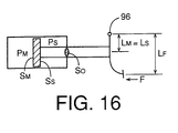
area SS of the assisting piston. That is, FS = PS·SS.Where the master cylinder and the assisting
cylinder are disposed in series with each other, as
illustrated in Fig. 16, the distances LS and LM are equal to
each other, and the brake operating force F can be estimated
according to the following equation:
F = (FM - FS) x LM/LF The pressure-receiving surface area SS of the
assisting piston is equal to (SM - S0), which is smaller
than the pressure-receiving surface area SM of the
pressurizing piston.Where the brake operating force detecting device
is adapted to detect, as the brake operating force F, a
reaction force F' applied from the pressurizing piston to
the brake operating member, the reaction force F' and the
brake operating force F have a relationship represented by
the following equation:
F' = F x LF/LM Therefore, the reaction force F' can be estimated
according to the following equation:
F' = FM - FS The feature of the above mode (25) is available
independently of the feature of any one of the above modes
(1)-(24). (26) A hydraulically operated braking system according
to any one of the above modes (1)-(25), wherein the master
cylinder includes a cylinder housing which cooperates with
the pressurizing piston to define the pressuring chamber,
the braking system further comprising a master cylinder
characteristic control device for controlling an amount of
the fluid in the pressurizing chamber of the master
cylinder, to thereby control a relationship between a
position of the pressurizing piston relative to the cylinder
housing and the fluid pressure in the pressurizing chamber.
In the braking system according to the above mode
(26), the amount of the fluid in the pressurizing chamber of
the master cylinder can be changed by the master cylinder
characteristic control device, so that the relative position
of the pressurizing piston and the cylinder housing can be
changed, whereby the relationship between this relative
position and the fluid pressure in the pressurizing chamber
can be changed by the master cylinder characteristic control
device. That is, the fluid pressurizing characteristic of
the master cylinder can be controlled by the master cylinder
characteristic control device. When the brake operating
member is operated, the pressurizing piston is advanced so
as to reduce the volume of the pressurizing chamber. When
the fluid is supplied from the master cylinder
characteristic control device to the pressurizing chamber,
upon operation of the brake operating member, the operating
stroke of the pressurizing piston is reduced by an amount
corresponding to the amount of the fluid supplied to the
pressurizing chamber. When the fluid is discharged from the
pressurizing chamber into the master cylinder characteristic
control device, the operating stroke of the pressurizing
piston is increased by an amount corresponding to the amount
of the fluid discharged from the pressurizing chamber.
Namely, the operating stroke of the pressurizing piston
decreases with an increase in the amount of the fluid
supplied to the pressurizing chamber, and increases with a
decrease in the amount of the fluid discharged from the
pressurizing chamber. Thus, the operating stroke of the
pressurizing piston can be controlled by controlling the
amount of the fluid in the pressurizing chamber, so that the
relationship between the operating stroke and the fluid
pressure in the pressuring chamber (hereinafter referred to
as "master cylinder pressure") can be controlled by the
master cylinder characteristic control device.The master cylinder characteristic control device
may be adapted to control the amount of the fluid in the
pressurizing piston, depending upon the operating stroke of
the pressurizing piston, or irrespective of the operating
stroke. The amount of the fluid to be supplied to or
discharged from the pressurizing chamber may be controlled
such that the master cylinder pressure linearly increases
with an increase in the operating stroke of the pressurizing
piston. Alternatively, a predetermined amount of the fluid
may be rapidly supplied from the master cylinder
characteristic control device to the pressurizing chamber
during an initial idling stroke of the brake operating
member following the initiation of an operation of the brake
operating member detected by a suitable switch. In the
former case, the master cylinder pressure is controlled to
correspond to the operating stroke of the brake operating
member, that is, the amount of operation of the brake
operating member by the operator. In the latter case, the
predetermined amount of the fluid to be suppled to the
pressurizing chamber may be equal to the amount of the fluid
required for the so-called "fast filling" of the master
cylinder, or a portion of the "fast filling" amount. In this
case, the required operating stroke of the brake operating
member can be reduced. Further, a predetermined constant
amount of the fluid may be supplied to the pressurizing
chamber for a unit amount of increase of the operating
stroke of the pressurizing piston. The required operating
stroke can be reduced with an increase in this constant
amount of the fluid. When the fluid is discharged from the
pressurizing chamber into the master cylinder characteristic
control device, the required operating stroke increases with
an increase in the amount of the fluid discharged from the
pressurizing chamber.As described above, the master cylinder
characteristic control device permits the operating stroke
of the pressurizing piston to be controlled with respect to
the master cylinder pressure. In this respect, the master
cylinder characteristic control device may be considered to
be a device for controlling the operating stroke of the
pressurizing piston. The control of the operating stroke
will become more apparent by the following explanation.The master cylinder pressure increases with an
operating force acting on the brake operating member as the
pressurizing piston is advanced with an operation of the
brake operating member by the operating force. If a certain
amount of the fluid is supplied from the master cylinder
characteristic control device to the pressurizing chamber
while the operating force is held constant, the pressurizing
piston is retracted by a distance corresponding to the
amount of the fluid supplied to the pressurizing chamber, so
that the required operating stroke of the pressurizing
piston is reduced. Conversely, if a certain amount of the
fluid is discharged from the pressurizing chamber into the
master cylinder characteristic control device, the required
operating stroke is increased. Thus, the master cylinder
characteristic control device is capable of controlling the
required operating stroke of the pressurizing piston.The feature of the above mode (26) is available
independently of the feature of any one of the features of
the above modes (1)-(25). (27) A hydraulically operated braking system according
to the above mode (26) , wherein the master cylinder
characteristic control device comprises: a cylinder housing;
a volume-changing piston received in the cylinder housing of
the master cylinder characteristic control device such that
the volume-changing piston is movable relative to the
cylinder housing of the master cylinder characteristic
control device, the volume-changing piston cooperating with
the cylinder housing of the master cylinder characteristic
control device to define a variable-volume chamber
communicating with the pressurizing chamber; and a fluid
amount control device for controlling a relative position of
the volume-changing piston and the cylinder housing of the
master cylinder characteristic control device, to control a
volume of the variable-volume chamber, for thereby
controlling the amount of the fluid in the pressurizing
chamber.
In the braking system according to the above mode
(27) wherein the pressurizing chamber and the
variable-volume chamber communicate with each other, the
amount of the fluid in the pressurizing chamber can be
controlled by controlling the volume of the variable-volume
chamber. The fluid is supplied into the pressurizing chamber
when the volume of the variable-volume chamber is reduced,
and the fluid is discharged from the pressurising chamber
when the volume of the variable-volume chamber is increased.
Thus, by controlling the amount of change of the volume of
the variable-volume chamber, the amount of the fluid to be
supplied to the pressurizing chamber and the amount of the
fluid to be discharged from the pressurizing chamber can be
controlled.The volume of the variable-volume chamber is
changed by moving the volume-changing piston. The
volume-changing piston may be moved by a fluid pressure or
an electric actuator such as an electric motor and a
piezoelectric device.Where the volume-changing piston is moved by a
fluid pressure, the cylinder housing of the master cylinder
characteristic control device cooperates with the
volume-changing piston to define a volume control chamber on
one side of the volume-changing piston which is remote from
the variable-volume chamber. The volume-changing piston is
moved to a position of equilibrium between the fluid
pressure in the volume control chamber and the fluid
pressure in the variable-volume chamber. In this case, the
fluid amount control device includes a high-pressure source,
a reservoir, a solenoid-operated pressure control valve
device connected to the high-pressure source, reservoir and
volume control chamber, and a control valve control device
for controlling the solenoid-operated pressure control valve
device to control the fluid pressure in the volume control
chamber. The cylinder housing and the volume control piston
which define the variable-volume chamber and the volume
control chamber are considered to constitute a master
cylinder characteristic control cylinder for controlling the
pressurizing characteristic of the master cylinder. This
master cylinder characteristic control cylinder may be
considered to be a stroke adjusting cylinder for adjusting
the operating stroke of the pressurizing piston and the
operating stroke of the brake operating member. The stroke
adjusting cylinder may be used to reduce the required
operating stroke of the pressurizing piston.Where the volume control piston is moved by a
drive force produced by an electric actuator. The position
of the volume control piston and the velocity of movement of
this piston can be controlled by controlling the electric
actuator. The fluid amount control device may include such
an electric actuator, a motion converting or transmitting
mechanism for transmitting a motion or displacement of the
electric actuator to the volume-changing piston, and an
actuator control device for controlling the electric
actuator. (28) A hydraulically operated braking system according
to the above mode (27), wherein the fluid amount control
device includes a master cylinder pressurizing control means
for controlling the amount of the fluid in the pressurizing
chamber, on the basis of an operating stroke of the
pressurizing piston and according to a predetermined rule.
In the braking system according to the above mode
(28), the fluid in the pressurizing chamber is controlled to
control the fluid pressurizing characteristic of the master
cylinder, on the basis of the operating stroke of the
pressurizing piston and according to the predetermined rule.
The relationship between the operating stroke of the
pressurizing piston and the amount of the fluid in the
pressurising chamber can be changed by changing the rule.
For instance, the predetermined rule may be a predetermined
relationship between the operating stroke S of the
pressurizing piston and the fluid pressure PM (master
cylinder pressure) in the pressurizing chamber of the master
cylinder. An example of this relationship is indicated by
solid line in Fig. 4, which relationship is represented by an
equation PM = k·S2 . The relationship may be represented by
an equation PM = k(S - a)2 + b.If the assisting drive force is controlled by the
assisting device force control device as described above with
respect to the above mode (2) of this invention, a
relationship between one power of the brake operating force
and the master cylinder pressure PM may be controlled as
indicated in the graph of Fig. 5, and a relationship between
the operating stiffness of the brake operating member and
the master cylinder pressure PM may be controlled as
indicated in the graph of Fig. 6. Each of these
relationships may be considered to be an example of the
fluid pressurizing characteristic of the master cylinder,
and may also be considered to be a characteristic of the
braking effect to be provided by the present braking system.
The power is a ratio of an amount of change of the master
cylinder pressure PM to an amount of change of a product of
the operating stroke S and force F of the brake operating
member. That is, the power is represented by [dPM/(S·dF =
F·dS)]. On the other hand, the operating stiffness is a
ratio of an amount of change of the operating force F to an
amount of change of the operating stroke S, that is, dF/dS. (29) A hydraulically operated braking system according
to any one of the above modes (26)-(28), wherein the master
cylinder characteristic control device has a variable-volume
chamber connected to a braking fluid chamber in the brake
cylinder and the pressurizing chamber of the master
cylinder, and includes a fluid amount control device for
controlling a volume of the variable-volume chamber to
control the amount of the fluid in the pressurizing chamber,
the braking system further comprising an emergency master
cylinder disconnecting device disposed between the
variable-volume chamber and the pressurizing chamber, the
emergency master cylinder disconnecting device being
normally placed in an open state for fluid communication
between the variable-volume chamber and the pressurizing
chamber, and brought to a closed state for disconnecting the
variable-volume chamber and the pressurising chamber from
each other in the event of an abnormality of the assisting
device.
The volume of the variable-volume chamber can be
controlled by the fluid amount control device. However, if
the volume of the variable-volume chamber is reduced while
the variable-volume chamber is disconnected from the
pressurizing chamber, the fluid pressure in the
variable-volume chamber is increased, Accordingly, the fluid
pressure in the braking fluid chamber in the brake cylinder
can be made higher than that in the pressurizing chamber, by
disconnecting the variable-volume chamber from the
pressurizing chamber, even in the event of abnormality of
the assisting device, that is, even if the fluid pressure in
the pressurizing chamber cannot be sufficiently increased
with the assisting drive force being Zero or extremely
small.The assisting device may include the assisting
cylinder, high-pressure source, reservoir, solenoid-operated
pressure control valve device and control valve control
device, as described above with respect to the above mode
(3), and the master cylinder characteristic control device
may include a master cylinder characteristic control
cylinder, and another set of a high-pressure source, a
reservoir, a solenoid-operated pressure control valve device
and a control valve control device, so that the volume of
the variable-volume chamber is controlled by the fluid
pressure in the master cylinder characteristic control
cylinder. In this case, a single high-pressure source may be
commonly used by the assisting device and the master
cylinder characteristic control device. If the pressure of
the pressurized fluid of the single high-pressure source is
lowered below a predetermined lower limit due to an
abnormality of the high-pressure source, it is difficult to
sufficiently pressurize the fluid in the variable-volume
chamber even when the emergency master cylinder
disconnecting device is switched to the closed state. In
this case, it is difficult to increase the fluid pressure in
the brake cylinder to be higher than that in the master
cylinder pressure. However, the pressurized fluid can be
supplied from the high-pressure source to the
variable-volume chamber of the master cylinder
characteristic control device, while the high-pressure
source is normal, even in the event of an abnormality of the
solenoid-operated pressure control valve device or control
valve control device of the assisting device, a fluid
leakage from the fluid passages connected to the
high-pressure source, reservoir, solenoid-operated pressure
control valve device and assisting pressure chamber, or a
failure of the assisting cylinder. Since the variable-volume
chamber can be pressurized by the high-pressure source, the
fluid pressure in the brake cylinder can be made higher than
that in the pressurizing chamber of the master cylinder.Where two high-pressure sources are provided for
the assisting device and the master cylinder characteristic
control device, respectively, or where the assisting device
includes the high-pressure source described above while the
master cylinder characteristic control device includes an
electric actuator such as an electric motor to control the
volume of the variable-volume chamber, it is also effective
to switch the emergency master cylinder disconnecting device
to the closed state in the event of an abnormality of the
high-pressure source of the assisting device.It is also effective to switch the emergency
master cylinder disconnecting device to the closed state in
the event of an abnormality of the assisting device, where
the assisting device is adapted to control the assisting
drive force by controlling an electric motor, as described
above with respect to the above made (4) while the master
cylinder characteristic control device includes the
high-pressure source, or where the assisting device and the
master cylinder characteristic control device have
respective electric actuators. (30) A hydraulically operated braking system
comprising: (a) a brake operating member operable by an
operator; (b) a master cylinder including a cylinder housing
and a pressurizing piston operatively connected to the brake
operating member and cooperating with the cylinder housing
to define a pressurizing chamber, the pressurizing piston
being moved by the brake operating member to pressurize a
fluid in the pressurizing chamber; (c) a brake cylinder
actuated by the pressurized fluid received from the master
cylinder; and (d) a master cylinder characteristic control
device for controlling an amount of the fluid in the
pressurizing chamber of the master cylinder, to thereby
control a relationship between a position of the
pressurizing piston relative to the cylinder housing and the
fluid pressure in the pressurizing chamber, for controlling
a fluid pressurizing characteristic of the master cylinder.
BRIEF DESCRIPTION OF THE DRAWINGS
The above and optional objects, features,
advantages and technical and industrial significance of this
invention will be further clarified by reading the following
detailed description of presently preferred embodiments or
forms of the invention, by reference to the accompanying
drawings, in which:
DETAILED DESCRIPTION OF THE PREFERRED EMBODIMENTS
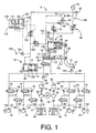
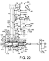
Referring first to Fig. 1, the hydraulically
braking system shown therein includes a normal braking
system and a servo system which are independent of each
other. The normal braking system includes a brake operating
member in the form of a brake pedal 10, a master cylinder
12, and wheel brake cylinders 22, 24, 26, 28 for respective
wheels 14, 16, 18, 20 of an automotive vehicle. The master
cylinder 12 is a tandem type cylinder having two
pressurizing chambers 30 and 32. A pressure of a working
fluid in these pressurizing chambers 30, 32 are pressurized
by an advancing movement of a pressurizing piston 34
operatively connected to the brake pedal 10. The fluid
pressure in the pressurizing chambers 30, 32 changes with an
operating force acting on the brake pedal 10. Two fluid
passages 36, 38 are connected to the respective pressurizing
chambers 30, 32.
Each of the fluid passages 36, 38 is split into
two branches. The wheel brake cylinders 22, 24 are connected
to the ends of the two branches of the fluid passage 36,
while the wheel brake cylinders 26, 28 are connected to the
ends of the two branches of the fluid passage 38. In each of
the four branches of the fluid passages 36, 38, there is
provided a pressure holding valve in the form of a
solenoid-operated shut-off valve 44. The branches of each
fluid passage 36, 38 are connected to a reservoir 46 through
fluid passages 47. Four pressure reducing valves in the form
of solenoid-operated shut-off valves 48 are provided in the
fluid passages 47 so that the fluid can be discharged from
the wheel brake cylinders 22, 24, 26, 28 into the reservoirs
46 through the respective pressure reducing shut-off valves
48 and the respective fluid passages 47. A check valve 49 is
provided in a by-pass passage which by-passes each of the
foul pressure holding shut-off valves 44. Each of the check
valves 49 allows a fluid flow in a direction from the
corresponding wheel brake cylinder 22, 24, 26, 28 towards
the master cylinder 12, and inhibits a fluid flow in the
opposite direction. The check valves 49 permit the fluid to
be rapidly returned from the wheel brake cylinders 22, 24,
26, 28 to the master cylinder 12 when the brake pedal 10 is
released from an operated position towards the non-operated
position while the pressure holding shut-off valves 44 are
placed in their closed positions.
The two reservoirs 46 are connected to the
respective fluid passages 36, 38 also through respective
fluid passages 50. In each of the fluid passages 50, there
are provided two check valves 52, 54, a pump 56 and a damper
58. The pump 56 is disposed between the two check valves 52,
54. The damper 58 functions to reduce pressure pulsation of
the fluid delivered from the pump 56. The two pumps 56 are
driven by a common electric motor 60.
In a portion of the fluid passage 36 between the
pressurizing chamber 30 and the point of branching, there is
provided a solenoid-operated shut-off valve 62. A stroke
adjusting cylinder 64 is connected to a portion of the fluid
passage 36 between the shut-off valve 62 and the point of
branching. These shut-off valve 62 and the stroke adjusting
cylinder 64 will be described.
The servo system of the present hydraulically
operated braking system includes a pump 70, an accumulator
72, a pressure increase control valve 74, a pressure
reduction control valve 76, a master reservoir 76 and an
assisting cylinder 78. The pressure increase control valve
74 and the pressure reduction control valve 75 are
controlled by a pressure control device 80 which is
constituted principally by a computer. It will be understood
from the following description that the above-indicated
elements 70-78 and a portion of the pressure control device
80 assigned to control the control valves 74, 75 cooperate
to constitute an assisting device 81 for boosting a drive
force to be applied to the pressurizing piston 32 of the
master cylinder 10. It will also be understood that the
pressure increase control valve 74 and the pressure
reduction control valve 75 constitute a major portion of a
solenoid-operated pressure control valve device 82 of the
assisting device 81.
The working fluid in the master reservoir 76 is
pumped up and pressurized by the pump 70, and the
pressurized fluid is stored in the accumulator 72. A
pressure switch 83 is provided to monitor whether the
pressure of the fluid stored in the accumulator 72 falls
within a predetermined range. An electric motor 84 for
driving the pump 70 is controlled according to an output
signal of the pressure switch 83, so that the fluid pressure
in the accumulator 72 is held substantially within the
predetermined range.
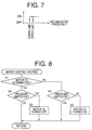
The pressure switch 83 has a plurality of
switching portions, so that the pressure switch 83 is turned
OFF when the fluid pressure in the accumulator 72
(hereinafter referred to as "accumulator pressure") is
lowered below a predetermined lower limit, and is turned ON
when the accumulator pressure rises above a predetermined
upper limit, as indicated in the graph of Fig. 7. The
electric motor 84 is turned ON when the pressure switch 83
is turned OFF, and is turned OFF when the pressure switch 83
is turned ON. The electric motor 84 is kept operated while
the pressure switch 83 is OFF, so that the accumulator
pressure is held within the predetermined range defined by
the lower and upper limits indicated above.
The electric motor 84 is controlled by the
pressure control device 80 depending upon the output signal
of the pressure switch 83, according to a motor control
routine illustrated in the flow chart of Fig. 8. This
routine is initiated with step S1 to determine whether the
electric motor 84 is in operation. If a negative decision
(NO) is obtained in step S1, the control flow goes to step
S2 to determine whether the pressure switch 83 is in the ON
state. If the pressure switch 83 is in the ON state, the
electric motor 84 is held OFF. If the pressure switch 83 is
in the OFF state, that is, if the accumulator pressure is
lower than the lower limit, a negative decision (NO) is
obtained in step S2, and the control flow goes to step S3 to
turn ON the electric motor 84. If an affirmative decision
(YES) is obtained in step S1, that is, if the electric motor
84 is in operation or in the ON state, step S4 is
implemented to determine whether the pressure switch 83 is
in the ON state. If the pressure switch 83 is in the ON
state, that is, if the accumulator pressure is higher than
the upper limit, a negative decision (NO) is obtained in
step S4, and the control flow goes to step S4 to turn OFF
the electric motor 60. If an affirmative decision (YES) is
obtained in step S4, the electric motor 84 is held in
operation.
A pressure relief valve 86 is provided between the
delivery side of the pump 70 and the reservoir 76, to
prevent an excessive rise of the delivery pressure of the
pump 70.
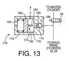
The assisting cylinder 78 includes a cylinder
housing 90, an assisting piston 92 fluid-tightly and
slidably received in the cylinder housing 90, and a return
spring 94 disposed between the assisting piston 92 and one
of the opposite axial ends of the cylinder housing 90.
As shown in Fig. 2, the assisting piston 92 is
operatively connected to the brake pedal 10 by a piston rod
95. The brake pedal 10 has a fulcrum 96 at an intermediate
portion thereof between the lower end having a pedal pad 97
and the upper end. The piston rod 95 engages a portion of
the brake pedal 10 between the fulcrum 96 and the upper end,
more precisely, near the upper end. On the other hand, the
pressurizing piston 34 of the master cylinder 12 is
operatively connected by a piston rod 98 to a portion of the
brake pedal 10 between the brake pad 97 and the fulcrum 96.
As indicated in Fig. 2, the points of engagement of the rods
95, 98 with the brake pedal 10 and the fulcrum 96 line on a
straight line, and the fulcrum 96 is spaced from the center
of the pedal pad 97 by a distance LF in the direction
parallel to the straight line. The point of engagement of
the rod 98 with the brake pedal 10 is spaced from the
fulcrum 96 by a distance LM, while the point of engagement
of the rod 95 with the brake pedal 10 is spaced from the
fulcrum 96 by a distance LS.
The rods 98 of the pressurizing piston 34 of the
master cylinder 12 and the rod 95 of the assisting piston 92
of the assisting cylinder 78 engage the brake pedal 10 such
that the rods 98, 95 are pivotable relative to the brake
pedal 10 and such that the engaging ends of the rods 98, 95
are movable relative to the brake pedal 10 in the
longitudinal direction of the brake pedal 10 (in the
direction parallel to the straight line indicated above). To
this end, the brake pedal 10 has elongate two elongate holes
99a while the rods 98, 95 have respective pins 99b engaging
the respective elongate holes 99a. In this arrangement, the
engaging ends of the rods 98, 95 are movable in the
longitudinal direction of the brake pedal 10 while
maintaining the predetermined constant distances LM, LS
between the fulcrum 96 and the engaging ends.
Referring back to Fig. 1, the cylinder housing 90
and the assisting piston 92 cooperate to define a spring
chamber and an assisting pressure chamber 100 on the
opposite sides of the assisting piston 92. The return spring
94 is disposed in the spring chamber, which communicates
with the atmosphere. The assisting pressure chamber 100
communicates with the accumulator 72 and the master
reservoir 76 through the pressure increase control valve 74
and the pressure reduction control valve 75, respectively.
The fluid pressure in the assisting pressure chamber 100 is
controllable by controlling the control valves 74, 75.
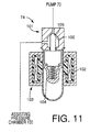
The pressure increase and pressure reduction
control valves 74 and 75 are identical in construction with
each other. The following description of the pressure
increase control valve 74 substantially applies to the
pressure reduction control valve 75. Tile pressure reduction
control valve 74 is disposed between the delivery side of
the pump 70 and the assisting pressure chamber 100. As shown
in Fig. 11, the pressure reduction control valve 74 includes
an electromagnetic force generating device 103, and a spring
104. The electromagnetic force generating device 103
includes a seating valve 101 and a coil 102. The seating
valve 101 has a valve member 105 and a valve seat 106. A
force corresponding to a fluid pressure difference across
the seating valve 101 acts on the valve member 105 in a
direction that causes the valve member 105 to be spaced away
from the valve seat 106. On the other hand, a biasing force
of the spring 104 acts on the valve member 105 in a
direction that causes the valve member 105 to be seated on
the valve seat 106. Further, an electromagnetic force
generated by application of an electric current to the coil
102 of the electromagnetic force generating device 103 acts
on the valve member 105 so as to move it away from the valve
seat 106. The electromagnetic force can be controlled by
controlling the electric current applied to the coil 102.
As described above, the force based on the fluid
pressure difference, the electromagnetic force and the
biasing force of the spring 104 act on the valve member 105
of the pressure increase control valve 74. The force based
on the fluid pressure difference and the electromagnetic
force act on the valve member 105 in the same direction, so
as to move the valve member 104 away from the valve seat
106, while the basing force of the spring 104 acts on the
valve member 105 in the opposite direction, so as to move
the valve member 105 to be seated on the valve seat 106.
Therefore, the pressure increase control valve 74 is held
open with the valve member 105 spaced apart from the valve
seat 106 while a sum of the force based on the fluid
pressure difference and the electromagnetic force is larger
than the biasing force of the spring 104. With the control
valve 74 placed in the open state, the pressurized fluid
delivered from the pump 70 is permitted to flow into the
assisting pressure chamber 100 of the assisting cylinder 78,
causing a rise of the fluid pressure in the chamber 100. The
fluid pressure difference required to hold the pressure
increase control valve 74 in the open state decreases with
an increase in the electromagnetic force, that is, with an
increase in the electric current applied to the coil 102.
Similarly, the pressure reduction control valve 75
is held open while the above-indicated sum is larger than
the biasing force of the return spring 104. In this open
state of the pressure reduction control valve 75, the
pressurized fluid is permitted to be discharged from the
assisting pressure chamber 100 into the master reservoir 76,
causing a reduction of the fluid pressure in the chamber
100. The fluid pressure in the chamber 100 is reduced as the
amount of electric current applied to the coil 102 of the
control valve 75 is increased.
The return spring 94 of the assisting cylinder 78
is provided in order to return the assisting piston 92 to
its original position when the brake pedal 10 is released.
Since the piston 92 is operatively connected to the brake
pedal 10 through the rod 95, the brake pedal 10 is also
returned to its original or non-operated position (fully
released position) when the piston 92 is returned by the
return spring 94. In this respect, the return spring 94 also
functions to return the brake pedal 10. The non-operated
position of the brake pedal 10 is defined by a suitable stop
member.
In the present first embodiment of this invention,
a normally-open solenoid-operated shut-off valve 108 is
provided between the assisting pressure chamber 100 and the
pressurizing chamber 32 of the master cylinder 12. While the
assisting device 81 iS normally operable, this shut-off
valve 108 is closed with an electric current applied to its
solenoid coil when the brake pedal 10 is operated. While the
assisting device 81 has any abnormality or defect, the
shut-off valve 108 is held closed even if the brake pedal 10
is operated. The abnormality indicated above, which will be
referred to as "first kind of abnormality", is an electrical
defect associated with the assisting device 81, such as a
failure of normal operation of the electric motor 84, and a
failure of application of an electric current to the
solenoid coil of the pressure increase control valve 74 or
pressure reduction control valve 75. In the event of
occurrence of the first kind of abnormality, no electric
current is applied to the solenoid coil of the shut-off
valve 108, whereby the shut-off valve 108 is opened. Even in
the presence of the first kind of abnormality, the assisting
cylinder 78 is normally operable.
A portion of the assisting device 81 assigned to
control the fluid pressure in the assisting pressure chamber
100 functions as an assisting drive force control device 109
for controlling an assisting drive force which is generated
by the assisting cylinder 78 and which is applied to the
pressurizing piston 34. The first kind of abnormality
indicated above may be considered to be an abnormality of
the assisting drive force control device 109. This assisting
drive force control device 109 may be considered to be an
electrically operated hydraulic pressure source. The first
kind of abnormality may be determined to be present if the
fluid pressure in the assisting pressure chamber 100 is
lowered below a predetermined threshold, or if the pressure
switch 83 is held in the OFF state for more than a
predetermined time. In this case, the first kind of
abnormality includes a failure to control the fluid pressure
in the assisting pressure chamber 100 due to a leakage of
the fluid from the hydraulic system.
The stroke adjusting cylinder 64 indicated above
includes a cylinder housing 110, and a volume-changing
piston or stroke adjusting piston 114 slidably received in
the cylinder housing 110. The cylinder housing 110 and the
stroke adjusting piston 114 cooperate to define two fluid
chambers 116, 118. The fluid chamber 116 is connected to the
fluid passage 36 indicated above, while the other fluid
chamber 118 is connected to the accumulator 72 through a
pressure increase control valve 122 and to the master
reservoir 76 through a pressure reduction control valve 124.
The fluid chamber 116 will be referred to as "a
variable-volume chamber", while the fluid chamber 118 will
be referred to as "a volume control chamber". A return
spring 126 is disposed in the variable-volume chamber 116,
so that the stroke adjusting piston 114 is biased by the
return spring 126 in a left direction as seen in Fig. 1,
namely, in the direction that causes an increase in the
volume of the variable-volume chamber 116.
The pressure increase control valve 122 and the
pressure reduction control valve 124 are identical in
construction with the pressure increase and pressure
reduction control valves 74, 75 described above. By
controlling the electric currents applied to the solenoid
coils of these control valves 122, 124, the fluid pressure
in the volume control chamber 118 of the stroke adjusting
cylinder 64 can be controlled.
When the stroke adjusting piston 114 is moved in
the right direction as seen in Fig. 1 with an increase in
the fluid pressure in the volume control chamber 118, the
volume of the variable-volume chamber 116 decreases, causing
an increase in the fluid pressure in the variable-volume
chamber 116, so that the pressurized fluid is fed from the
variable-volume chamber 116 into the pressurizing chamber 30
of the master cylinder 12. When the stroke adjusting piston
114 is moved in the left direction with a decrease in the
fluid pressure in the volume control chamber 118, the fluid
in the pressurizing chamber 30 is discharged into the
variable-volume chamber 116. Thus, the operating stroke of
the brake pedal 10 can be adjusted by controlling the fluid
pressure in the volume control chamber 118, that is, by
controlling the fluid pressure in the volume control chamber
118 to control the volume of the fluid in the
variable-volume chamber 114 when the brake pedal 10 is
depressed, that is, when the pressurising piston 34 is moved
in left direction. Described more specifically, the
operating stroke of the brake pedal 10 is reduced with an
increase in the amount of the fluid which is supplied from
the variable-volume chamber 116 to the pressurizing chamber
30 so as to move the pressurising piston 34 in the right
direction. Conversely, the operating stroke of the brake
pedal 10 is increased with a decrease in the amount of the
fluid supplied to the pressurizing chamber 30.
As described above, the operating stroke of the
brake pedal 10 can be controlled by controlling the fluid
pressure in the volume control chamber 118 to control the
volume of the variable-volume chamber 116 and the amount of
the fluid in the pressurizing chamber 30 when the brake
pedal 10 is depressed. The original or neutral position of
the stroke adjusting piston 114 when the brake pedal 10 is
in the non-operated or fully released position is determined
by equilibrium between a force acting on the piston 114
based on the fluid pressure in the volume control chamber
118 and a biasing force of the return spring 126 acting on
the piston 114. It will be understood that a stroke
adjusting device 128 is constituted by the stroke adjusting
cylinder 64, pressure increase control valve 122, pressure
reduction control valve 124, accumulator 72, pump 70,
electric motor 84, master reservoir 76, and a portion of the
pressure control device 80 assigned to control the control
valves 122, 124.
The solenoid-operated shut-off valve 62 is a
normally-open valve, which is held open while the assisting
device 81 is normally operable. When the assisting device 81
has any abnormality, that is, when either of the pressure
increase and pressure reduction control valves 74, 75 has
any abnormality, with the accumulator 72 and pump 70 being
normally operable, the shut-off valve 62 is closed. In this
event, the fluid pressure in the assisting pressure chamber
100 of the assisting cylinder 78 cannot be controlled, but
the fluid pressure in the volume control chamber 118 of the
stroke adjusting cylinder 64 can be controlled by
controlling the pressure increase and pressure reduction
control valves 122, 124, since the accumulator 72 and the
pump 70 are normally operable. Accordingly, the fluid
pressure in the variable-volume chamber 116 can be made
higher than that in the pressurizing chamber 30, by reducing
the volume of the variable-volume chamber 116 by increasing
the fluid pressure in the volume control chamber 118. The
abnormality of the control valves 74, 75 indicated above
will be referred to as "a second kind of abnormality" of the
assisting device 81. This second kind of abnormality can be
detected by detecting that the fluid pressure in the
assisting pressure chamber 100 is lower than a predetermined
lower limit even while the pressure switch 83 is in the ON
state. Even in the presence of the second kind of
abnormality, the fluid pressures in the wheel brake
cylinders 22, 24 can be made higher than the fluid pressure
in the pressurizing chamber 30, owing to the fluid pressure
in the variable-volume chamber 116 of the stroke adjusting
cylinder 64 which is disconnected from the pressurizing
chamber 30 by the shut-off valve 62. In this case, the fluid
pressure in the pressurizing chamber 32 is applied to the
wheel brake cylinders 26, 28.
The pressure control device 80 is principally
constituted by a computer incorporating a central processing
unit (CPU) 130, a random-access memory (RAM) 131, a
read-only memory (ROM) 132, an input portion 133 and an
output portion 134. The input portion 133 receives output
signals of wheel speed sensors 140, 142 144, 146 for the
wheels 13, 16, 18, 20, a force sensor 148 for detecting the
operating force F acting on the brake pedal 10, a stroke
sensor 150 for detecting the operating stroke S of the brake
pedal 10, an assisting pressure sensor 152 for detecting the
fluid pressure in the assisting pressure chamber 100, a
stroke control pressure sensor 154 for detecting the fluid
pressure in the variable-volume chamber 118, and a master
cylinder pressure sensor 156 for detecting the fluid
pressure in the pressurizing chamber 30 of the master
cylinder 12.
To the output portion 134, there are connected
driver circuits for energizing the solenoid coils of the
pressure increase control valves 74, 122, pressure reduction
control valves 75, 124, pressure holding and increasing
shut-off valves 44, 48, and shut-off valves 62, 108, and
driver circuits for energizing the electric motors 60, 84.
The ROM 132 stores various control programs including the
control program for the motor control routine illustrated in
the flow chart of Fig. 8 described above, an anti-lock
braking pressure control program, an assisting drive force
control program for controlling the fluid pressure in the
assisting pressure chamber 100, a stroke adjusting control
program for controlling the fluid pressure in the volume
control chamber 118, and control programs for controlling
the various solenoid-operated shut-off valves such as the
shut-off valves 62, 74, 75, 108, 122, 124. The ROM 132
further stores control data maps represented by the graphs
of Figs. 3 and 4, which are used to control the fluid
pressure in the assisting pressure chamber 100.
The force sensor 148 detects the operating or
depression force F acting on the pedal pad 97 of the brake
pedal 10. For instance, the force sensor 148 uses an elastic
member attached to the pedal pad 97, so that the operating
force F is detected based on an amount of elastic
deformation or strain of the elastic member.
The master cylinder pressure sensor 156, which
detects the fluid pressure in the pressurizing chamber 30,
is disposed in a portion of the fluid passage 36 which is
located downstream of the solenoid-operated shut-off valve
62. Accordingly, the pressure sensor 156 cannot detect the
fluid pressure in the chamber 30 when the shut-off valve 62
is in the closed position. In this case, the output of the
pressure sensor 156 represents the fluid pressure applied to
the wheel brake cylinders 22, 24.
An assisting pressure force acting on the
assisting piston 92 can be obtained on the basis of the
fluid pressure in the assisting pressure chamber 100. Based
on this assisting pressure force, an assisting drive force
is applied to the pressurizing piston 34 through the brake
pedal 10. On the other hand, the operating stroke S of the
brake pedal 10 is determined by the amounts of the fluid in
the pressurising chamber 30 and the variable-volume chamber
116, which amounts are determined by the fluid pressure In
the volume control chamber 118 and the pressurizing chamber
30. In the present embodiment, the fluid pressure in the
assisting pressure chamber 100 is controlled so that the
master cylinder pressure PM (fluid pressure in the
pressurizing chamber 30) changes with the operating force F
of the brake pedal 10, according to a predetermined
relationship between the master cylinder pressure PM and the
operating force F, as indicated in the graph of Fig. 3. On
the other hand, the fluid pressure in the volume control
chamber 118 is controlled so that the master cylinder
pressure PM changes with the operating stroke S of the brake
pedal 10, according to a predetermined relationship between
the master cylinder pressure PM and the operating stroke S,
as indicated in the graph of Fig. 4.
On the basis of the rotating speeds of the wheels
14-20 detected by the wheel speed sensors 140-146, an
estimated running speed of the automotive vehicle is
obtained, and the slipping speed or locking condition of
each wheel is estimated on the basis of the detected wheel
speeds and the estimated vehicle running speed. The pressure
holding and pressure reducing shut-off valves 44, 48 are
controlled to control the fluid pressures in the wheel brake
cylinders 22-28 in an anti-lock fashion, according to the
estimated locking conditions of the wheels 14-20.
An operation of the present hydraulically operated
braking system constructed as described above will be
described.
When the brake pedal 10 is depressed with the
operating force F, the solenoid-operated shut-off valve 108
is brought to the closed position while the
solenoid-operated shut-off valve 62 is held in its open
position, where the assisting device 81 is normal. The fluid
pressure in the assisting pressure chamber 100 is controlled
to control the assisting drive force. The fluid pressure in
the volume control chamber 118 has been controlled to adjust
the operating stroke S of the brake pedal.
Initially, an operation to control the fluid
pressure PS in the assisting pressure chamber 100 to control
the fluid pressure PM in the pressurizing chambers 20, 32
will be described, by reference to Fig. 2. In the present
embodiments, the pressurizing piston 34 has a
pressure-receiving surface area SM which is larger than a
pressure-receiving surface area SS of the assisting piston
92. That is, SM > SS. Further, a product of the
pressure-receiving surface area SM and the distance LM
(between the fulcrum 96 and the engaging end of the rod 98)
is larger than a product of the pressure-receiving surface
area SS and the distance LS (between the fulcrum 96 and the
engaging end of the rod 95). That is, SM x LM > SS x LS .
An equilibrium of moments about the fulcrum 96 of
the brake pedal 10 is expressed by the following equation:
FS x LS + F x LF = FM x LM
The force FS is the assisting pressure force
acting on the assisting piston 92 based on the fluid
pressure PS in the assisting pressure chamber 100. This
assisting pressure force FS is applied to the brake pedal
10. The force FM, which is a wheel braking force, is a
reaction force which is applied to the brake pedal 10 based
on the fluid pressure PM in the pressurizing chambers 30,
32. The wheel braking force FM is expressed by the following
equation:
FM = FS x LS/LM + F x LF/LM
The first term (FS x LS/LM) in the right member of
the above equation is a force to be applied to the
pressurizing piston 34 based on the assisting pressure force
FS. The force (FS x LS/LM) is referred to as the assisting
drive force. On the other hand, the second term (F x LF/LM)
is a force to be applied to the pressurizing piston 34 based
on the operating force F. The force (F x LF/LM) is referred
to as the primary drive force. Thus, the assisting drive
force in addition to the primary drive force is applied to
the pressurizing piston 34, so that the wheel braking force
is made larger in the present braking system than that in a
braking system not provided with the assisting device 81.
On the other hand, the assisting pressure force FS
is expressed by the following equation:
FS = PS x SS
The wheel braking force FM is also expressed by
the following equation:
FM = PM x SM
Therefore, the fluid pressure PM in the master
cylinder 12 is expressed by the following equation:
PM = PS x SS x LS/(LM x SM) + F x LF/(LM x SM)
The master cylinder pressure PM is determined on
the basis of the detected operating force F and according to
the PM-F relationship of Fig. 3 represented by a data map
stored in the ROM 132. Accordingly, a target value of the
fluid pressure PS in the assisting pressure chamber 100 is
determined according to the above equation, and the pressure
increase control valve 74 and the pressure reduction control
valve 75 are controlled so as to establish the determined
target value of the fluid pressure PS.
When the fluid pressure PS in the assisting
pressure chamber 100 is α times the fluid pressure PM of the
master cylinder 12, that is, when PS = α x PM , the master
cylinder pressure PM and the wheel braking force FM are
expressed by the following equations, respectively:
PM = F x LF/(LM x SM - α x LS x SS) FM = F x LF x SM/(LM x SM - α x LS x SS)
It will be understood that the boosting ratio of
the master cylinder pressure PM and the wheel braking force
FM increase with the value of α.
As described above, the fluid pressure PS in the
assisting pressure chamber 100 is controlled so that the
master cylinder pressure PM increases with the operating
force F, according to the predetermined PM-F relationship as
indicated in the graph of Fig. 3. According to this
relationship, the master cylinder pressure PM increases with
the operating force F according to an equation PM = k x F1/2
or PM = k x F2/3 , while the operating force F is considerably
small. This arrangement permits a rapid rise of the master
cylinder pressure PM and a rapid increase of the wheel
braking force. While the operating force F is relatively
large, the master cylinder pressure PM increases as a
quadratic function of the operating force F, that is,
according to an equation PM = k x F2 , so that the rate of
increase of the master cylinder pressure PM (wheel braking
force) with the operating force F is comparatively low while
the operating force F is in a medium range as indicated in
Fig. 3, and so that the rate of increase of the master
cylinder pressure PM is comparatively high while the
operating force F is considerably large. In this
arrangement, the accuracy of control of the wheel braking
force is relatively high, but the braking sensitivity is
relatively low, while the operating force F is in the medium
range. While the operating force F is considerably large,
the wheel braking force is sufficiently large, and the
braking sensitivity is relatively high, that is, the amount
of increase of the wheel braking force per a given amount of
increase of the operating force F is relatively large.
The fluid pressure in the volume control chamber
118 of the stroke adjusting cylinder 64 is controlled so
that the master cylinder pressure PM increases with the
operating stroke S according to the predetermined PM-S
relationship as indicated in the graph of Fig. 4. According
to this relationship, the master cylinder pressure PM
increases as a quadratic function of the operating stroke S,
namely, according to an equation PM = k' x S2 . In this
arrangement, the accuracy of control of the wheel braking
force is relatively high while the operating stroke S is
relatively small, and the rate of increase of the master
cylinder pressure PM with the operating stroke S is
relatively high while the operating stroke S is relatively
large. The operating stroke S is detected by the stroke
sensor 150.
It is also noted that a relationship between the
master cylinder pressure PM and a power (efficiency) of the
operating force F, and a relationship between the master
cylinder pressure PM and an operating stiffness of the brake
pedal 10 can be controlled by controlling the relationship
between the master cylinder pressure PM and the operating
force F and the relationship between the master cylinder
pressure PM and the operating stroke S.
The power of the operating force F is represented
by dPM/(F x dS + S x dF), while the operating stiffness is
represented by dF/dS. The power dPM/(F x dS + S x dF) and
the operating stiffness dF/dS will be considered in a case
where the fluid pressure PS in the assisting pressure
chamber 100 is controlled so that the master cylinder
pressure PM increases with the operating force F according
to the equation PM = k x F2, while the fluid pressure in the
volume control chamber 118 is controlled so that the master
cylinder pressure PM increases with the operating stroke S
according to the equation PM = k' x S2 . In these equations,
k and k' are constants, which may be changed as desired by
controlling the fluid pressure PS in the assisting pressure
chamber 100. In the present case, the power dPM/(F x dS + S
x dF) is held constant at √(kk'), as indicated in the graph
of Fig. 5, and the operating stiffness dF/dS is also held
constant at √(k'/k).
By controlling the fluid pressure PS in the
assisting pressure chamber 100 and the fluid pressure in the
volume control chamber 118 of the stroke adjusting cylinder
64 according to the above equations PM = = k x F2 , and PM =
k' x S2 , as described above, the power dPM/(F x dS + S x dF)
is held constant, so that the rate of increase of the wheel
braking force with the braking effort of the vehicle
operator applied to the brake pedal 10 is held constant,
making it possible to give the vehicle operator a brake
operating feel that the braking effect increases linearly
with an increase in the braking effort by the vehicle
operator. Further, the operating stiffness dF/dS is also
held constant, so that the vehicle operator operating the
brake pedal 10 has a highly consistent brake operating feel.
In addition, the constant values √(kk') and √(k'/k) of the
power and operating stiffness can be changed to change the
braking effect characteristic, by changing the constants k
and k'.
Then, the power dPM/(F x dS + S x dF) and the
operating stiffness dF/dS will be considered in another case
where the fluid pressure PS in the assisting pressure
chamber 100 and the fluid pressure in the volume control
chamber 118 are controlled so that the master cylinder
pressure PM increases with the operating force F and the
operating stroke S according to the equations PM = k x F2/3
and PM = k' x S2 , respectively. In this case, the power
changes as a function of PM -1 that is, the power is
represented by {√(k3k')/2PM}, while the operating stiffness
changes as a function of PM, as indicated in Fig. 6, that
is, the operating stiffness is represented by {3√(k'/k3) x
PM }.
By controlling the fluid pressure PS in the
assisting pressure chamber 100 and the fluid pressure in the
volume control chamber 118 of the stroke adjusting cylinder
64 according to the above equations PM = = k x F2/3 , and PM =
k' x S2 , as described above, the power dPM/(F x dS + S x dF)
is larger when the wheel braking force is relatively small
than when it is relatively large, so that the rate of
increase of the wheel braking force with the braking effort
of the vehicle operator applied to the brake pedal 10 is
higher when the wheel braking force (braking effort) is
relatively small than when it is relatively large.
Accordingly, the vehicle operator feels a relatively high
rate of increase of the braking effect with an increase in
the braking effort applied to the brake pedal 10. Further,
the operating stiffness of the brake pedal 10 increases with
the braking effort at a relatively high rate, so that the
vehicle operator feels a relatively high degree of operating
stiffness of the brake pedal 10.
The power and the operating stiffness will be
further considered in a case where the fluid pressure PS in
the assisting pressure chamber 100 and the fluid pressure in
the volume control chamber 118 are controlled so that the
master cylinder pressure PM changes as ordinary quadratic
functions of the operating force F and the operating stroke
S, that is, according to the following equations,
respectively:
PM= k(F - a)2 + b PM = k'(S - c)2 + d
In the above equations, a, b, c and d are
constants, which can be changed as desired by controlling
the fluid pressure PS in the assisting pressure chamber 100.
In the present case, the operating stiffness dF/dS
is represented by √{k'(PM - d)/k(PM - b)}. Where the
constant b is equal to the constant d, the value √{k'(PM -
d)/k(PM - b)} is constant at √(k'/k). Further, the power
dPM/(F x dS + S x dF) is represented by 2√(kk')XY/(X2 + Y2 +
a√kX +c√k'Y), where X represents √(PM - b) while Y
represents √(PM - d). Where the constants a and c are zero,
and X is equal to Y (b = d), the value 2√(kk')XY/(X2 + Y2 +
a√kX +c√k'Y) is constant at √(kk'). Where the constants a, c
and d are zero, the power is represented by 2√(kk)√{PM(PM -
b)}/(2PM - b).
The power and the operating stiffness will be
further considered in a case where the fluid pressure PS in
the assisting pressure chamber 100 and the fluid pressure in
the volume control chamber 118 are controlled so that the
master cylinder pressure PM changes with the operating force
F and the operating stroke S, according to the following
equations, respectively:
PM = k(F - a) 2/3 PM = k'(S - c)2 + d
In the present case, the operating stiffness dF/dS
is represented by the following equation:
dF/dS = 3√(k'/k3) x √{PM(PM - d)}.
The above equation can be converted into the
following equation according to the Taylor's Theorem:
dF/dS ≒ 3√(k'/k3) x √{PM(PM - d/2}}
It will thus be understood that the operating
stiffness dF/dS changes linearly as a function of the master
cylinder pressure PM. This is true even where the constant d
is equal to zero. Accordingly, the operating stiffness
increases with an increase in the wheel braking force.
On the other hand, the power dPM/(F x dS + S x dF)
is represented by 2k√(kk')M/N3 + ak3/2 + 3c√k'MN + 3M2N),
where M represents √(PM - d) while N represents √PM. Where
the constants c and d are zero, the power is represented by
2k√(kk')/(4PM + ak3/2/√PM).
While the present embodiment is adapted to control
the fluid pressures in the assisting pressure chamber 100
and volume control chamber 118 according to the specific
PM-F and PM-S relationships shown in Figs. 3 and 4, it is to
be understood that the fluid pressures may be controlled
according to other relationships. For instance, a plurality
of different PM-F and/or PM-S relationships may be used
corresponding to respective ranges of the operating force F
and/or operating stroke S.
It is also possible to control the fluid pressures
in the assisting pressure chamber 100 and volume control
chamber 118, depending upon the vehicle running speed and
the operating speed of the brake pedal 10, rather than the
operating force F and stroke S. For instance, the fluid
pressure PS in the assisting pressure chamber 100 may be
controlled so that the master cylinder pressure PM (wheel
braking force) increases with the vehicle running speed V,
such that the rate of increase of the pressure PM increases
with an increase of the vehicle running speed V, as
indicated by solid line in the graph of Fig. 9, in which
broken line indicates the PM-V relationship where the
pressure PS is controlled so that the master cylinder
pressure PM increases with the operating force F according
to the PM-F relationship as indicated in the graph of Fig.
3. In the case of control indicated by the solid line of
Fig. 9, the wheel braking force is sufficiently increased
when the vehicle is running at a relatively high speed,
making it possible to reduce the required stopping distance
of the vehicle upon brake application at the relatively high
speed. The vehicle running speed V used may be a speed
during or upon brake application to the vehicle.
Further, the fluid pressure PS may be controlled
so that the master cylinder pressure PM (wheel braking
force) increases with the operating speed dF/dt of the brake
pedal 10, such that the rate of increase of the pressure PM
increases with an increase in the operating speed dF/dt, as
indicated by solid line in the graph of Fig. 10. When the
operating speed dF/dt of the brake pedal 10 is relatively
high, it means an emergency brake application, or a desire
of the vehicle operator to abruptly stopping or decelerating
the running vehicle. The operating speed dF/dt may be
obtained on the basis of a rate of change of the level of
the output signal of the force sensor 148, or alternatively
on the bases of a rate of change of the master cylinder
pressure PM while the fluid pressure PS in the assisting
pressure chamber 100 is held constant. Further, the
operating speed dF/dt may be obtained on the basis of a rate
of change of the level of the output signal of the stroke
sensor 150. In this case, however, it is desirable to obtain
the operating speed while the fluid pressure in the volume
control chamber 118 is held constant.
It is also possible to control the fluid pressures
in the assisting pressure chamber 100 and volume control
chamber 118, depending upon the friction coefficient µ of
the road surface and/or the viscosity of the working fluid.
For instance, the fluid pressure PS may be controlled so
that the rate of increase of the wheel braking force with
the friction coefficient µ decreases with a decrease in the
friction coefficient µ, or so that the assisting drive force
FS x LS/LM decreases with a decrease in the friction
coefficient µ. Further, the fluid pressure PS may be
controlled so that the assisting drive force increases to
increase the master cylinder pressure PM with an increase in
the viscosity of the working fluid, since the force
transmitting velocity decreases with the increase in the
fluid viscosity.
Further, both of the fluid pressures in the
assisting pressure chamber 100 and volume control chamber
118 need not be controlled. Namely, only the fluid pressure
in the assisting pressure chamber 100 or the volume control
chamber 118 may be controlled.
It is noted that upon releasing of the brake pedal
10, the fluid in the assisting pressure chamber 100 is
returned to the master reservoir 76 through the pressure
reduction control valve 75. That is, the control valve 75 is
held in the open position for a predetermined time after the
brake pedal 10 has been released.
It is also noted that the assisting device 81 may
be used as an automatic braking device, which is
automatically activated without an operation of the brake
pedal 10, when a predetermined condition is satisfied. For
instance, where the vehicle has a sensor for detecting a
distance between the vehicle front and any object such as a
person in front of the vehicle, the fluid pressure PS in the
assisting pressure chamber 100 is raised to apply a brake to
the vehicle to avoid a collision of the vehicle with the
object, when the detected distance has become smaller than a
predetermined threshold. In this case, the force based on
the fluid pressure in the assisting pressure chamber 100 is
transmitted to the pressurizing piston 34 through the brake
pedal 10, so that the piston 34 is automatically advanced to
increase the master cylinder pressure PM, namely, the
pressure in the pressurizing chambers 30, 32, for applying
an automatic brake to the vehicle, without the vehicle
operator depressing the brake pedal 10.
On the other hand, an anti-lock braking pressure
control operation is performed by controlling the
solenoid-operated pressure holding and reducing shut-off
valves 44, 48, so as to regulate the fluid pressure in each
of the wheel brake cylinders 22, 24, 26, 28 so that the
amount of slip of each wheel 14, 16, 18, 20 is held within
an optimum value. The anti-lock braking pressure control
operation for each wheel is initiated when the amount of
slip of the wheel on the road surface during brake
application to the vehicle has become excessive with respect
to the friction coefficient of the road surface. During the
anti-lock braking pressure control operation, the fluid
pressure PS in the assisting pressure chamber 100 is
controlled to be held at a predetermined level which is low
enough to reduce an influence of the pressure PS on the
anti-lock braking pressure control operation.
There will next be described an operation of the
present braking system in the event of occurrence of an
abnormality of the assisting device 81. When the first kind
of abnormality of the assisting device 81 explained above
occurs, the solenoid-operated shut-off valve 108 is brought
to its open state, and the solenoid-coils of the pressure
increase control valve 74 and pressure reduction control
valve 75 are de-energized, so that the assisting pressure
chamber 100 is disconnected from both of the accumulator 72
and the master reservoir 76, and is communicated with the
pressurizing chamber 32. When the brake pedal 10 is
depressed in this condition, the pressurized fluid in the
pressurizing chamber 32 is supplied to the assisting
pressure chamber 100, and the assisting piston 92 is moved.
When the brake pedal 10 is released, the pressurized fluid
is returned from the assisting pressure chamber 100 back to
the pressurizing chamber 32, and to the master reservoir 76.
If the pressurizing chamber 32 were not communicated with
the assisting pressure chamber 100 through the shut-off
valve 108, the fluid flows into and from the assisting
pressure chamber 100 would be inhibited, preventing a
movement of the assisting piston 92, and therefore a
movement of the brake pedal 10. In the present embodiment
wherein the shut-off valve 108 is opened in the event of
occurrence of the first kind of abnormality of the assisting
device 81, the brake pedal 10 can be depressed even in that
event.
With the assisting pressure chamber 100 held in
communication with the pressurizing chamber 32 through the
open solenoid-operated shut-off valve 108, the fluid
pressure in the assisting pressure chamber 100 is made equal
to the fluid pressure PM' in the pressurizing chamber 32.
The fluid pressure PM' is represented by the following
equation:
PM' = F x LF/(LM x SM - LS x SS)
In the present embodiment wherein the inequality
LM x SM > LS x SS is satisfied, the fluid pressure PM' is
prevented from being a negative pressure. That is, although
the communication between the pressurizing chamber 32 and
the assisting pressure chamber 100 causes the working fluid
to flow from the pressurizing chamber 32 into the assisting
pressure chamber 100, the fluid pressure in the pressurizing
chamber 32 will not fall below the atmospheric pressure, so
that the fluid will not be discharged from the wheel brake
cylinders 26, 28 into the pressurizing chamber 32.
Accordingly, the wheel brake cylinders 26, 28 can be
actuated by the fluid pressure pressurized in the
pressurizing chamber 32.
The fluid pressure PM in the pressurizing chamber
32 when the assisting drive force is zero is represented by
the following equation:
PM = F x LF/(LM x SM)
Therefore, the fluid pressure PM' when the
pressurizing chamber 32 is in communication with the
assisting pressure chamber 100 is represented by the
following equation including the fluid pressure PM:
PM' = PM x LM x SM/(LM x SM - LS x SS)
Thus, a ratio of the fluid pressure PM' when the
shut-off valve 108 is open to the fluid pressure PM when the
assisting drive force is zero is represented by the
following equation:
PM'/PM = 1/{ 1- (LS x SS/LM x SM )}
Since the value (LS x SS/LM x SM) is smaller than
1 as described above, it will be apparent that the
above-indicated ratio PM'/PM is larger than 1. Namely, the
wheel braking force when the pressurizing chamber 32 is in
communication with the assisting pressure chamber 100 in the
event of the first kind of abnormality of the assisting
device 81 is larger than when the assisting drive force is
zero.
On the other hand, the solenoid-operated shut-off
valve 62 is held in the open state, and the fluid pressure
in the volume control chamber 118 is held constant. In the
presence of an electrical abnormality the solenoid coils of
the pressure increase control valve 122 and the pressure
reduction control valve 124 are de-energized, and the stroke
adjusting cylinder 64 is not operable to adjust the
operating stroke S.
In the event of occurrence of the second kind of
abnormality of the assisting device 81 described above, the
shut-off valve 62 is brought to the closed state, and the
solenoid coils of the pressure increase and pressure
reduction control valves 74, 75 are de-energized, while the
shut-off valve 108 is brought to the open state as in the
event of occurrence of the first kind of abnormality. In
this condition, the fluid pressure in the variable-volume
changer 116 can be made higher than that in the pressurizing
chamber 32, by controlling the fluid pressure in the volume
control chamber 118 while the variable-volume chamber 116 is
disconnected from the master cylinder 12 by the closed
shut-off valve 62. Thus, the fluid pressure in the wheel
brake cylinders 22, 24 can be made higher than the fluid
pressure in the master cylinder 12. In this sense, the
stroke adjusting cylinder 64 also functions as a device for
increasing the fluid pressure in the wheel brake cylinders
22, 24 in the event of occurrence of the second kind of
abnormality.
The shut-off valve 62 may be brought to the closed
state also when the assisting cylinder 78 has an
abnormality, such as a failure to move the assisting piston
92. In this case, too, the pressurized fluid can be supplied
from the stroke adjusting cylinder 64 to the wheel brake
cylinders 22, 24. This abnormality can be detected if the
master cylinder pressure PM or the assisting pressure drive
force FS is lower or smaller than a predetermined threshold
while the operating force F is larger than a predetermined
value. In this case, it is desirable to hold the shut-off
valve 108 in the closed state, for preventing the fluid to
be discharged from the pressurizing chamber 32 into the
assisting pressure chamber 100.
As described above, the present hydraulically
operated braking system is constructed to electrically
control the fluid pressure in the assisting pressure chamber
100, permitting an electrical control of the assisting drive
force to be applied to the pressurizing piston 34 of the
master cylinder 12, so that the master cylinder pressure PM
can be controlled to a level in a non-proportional
relationship with the operating force F of the brake pedal
10. That is, the relationship between the master cylinder
pressure and the brake pedal operating force can be changed
as desired. Further, the present braking system is equipped
with the stroke adjusting device 128 including the stroke
adjusting cylinder 64 having the volume control chamber 118
whose fluid pressure can also be electrically controlled, so
that the relationship between the master cylinder pressure
and the brake pedal operating stroke can also be changed as
desired. The stroke adjusting device 128 can be utilized as
a device for activating the wheel brake cylinders 22, 24
with a relatively high fluid pressure, in the event of
abnormality of the assisting device 81. The utilization of
the stroke adjusting device 128 makes it possible to apply a
relatively high braking pressure to the wheel brake
cylinders 22, 24, without increasing the structural
complexity of the braking system. Even if the pressure
increase and pressure reduction control valves 74, 74 are
not normally operable, the electrical control to close the
shut-off valve 62 permits the stroke adjusting cylinder 64
to activate the wheel brake cylinders 22, 24 with the
pressurized fluid supplied from the accumulator 72. Further,
the electrical control to open the shut-off valve 108 in the
event of an abnormality of the assisting drive force control
device 109 permits the brake pedal operating force to be
boosted.
It will be understood from the foregoing
description of the present first embodiment of the invention
that a portion of the pressure control device 80 assigned to
control the pressure increase and pressure reduction control
valves 74, 75 constitutes a major portion of a control valve
control device for controlling the control valves 74, 75,
while the solenoid-operated shut-off valve 108 and a portion
of the pressure control device 80 assigned to open the
shut-off valve 108 constitute an emergency fluid
communicating device for effecting fluid communication
between the pressurizing chamber 32 and the assisting
pressure chamber 100 in the event of an abnormality of the
assisting device 81. Since the fluid pressurizing
characteristic of the master cylinder 12 is controlled by
adjusting the operating stroke S by the stroke adjusting
device 128, the stroke adjusting device 128 may be
considered to be one form of a master cylinder
characteristic control device for controlling the fluid
pressurizing characteristic of the master cylinder 12. Since
the fluid pressurizing characteristic of the master cylinder
12 can also be controlled by controlling the assisting drive
force produced by the assisting device 81, the assisting
device 81 including the assisting drive force control device
108 may be considered to be another form of the master
cylinder characteristic control device. While both of the
assisting device 81 and the stroke adjusting device 128 may
be considered to be the master cylinder characteristic
control device, each of these two devices 81, 128 may be
considered to be the master cylinder characteristic control
device, since either the device 81 or the device 128 alone
can change the fluid pressurizing characteristic of the
master cylinder 12. It will further be understood that the
stroke adjusting cylinder 64 having the volume control
chamber 118 and a portion of the pressure control device 80
assigned to control the fluid pressure in the chamber 118
constitute a master cylinder fluid amount control device for
controlling the amount of the fluid in the master cylinder
12 to adjust the operating stroke S of the brake pedal 10,
and that the shut-off valve 62 and a portion of the pressure
control device 80 assigned to close the shut-off valve 62
constitute an emergency master cylinder disconnecting device
for disconnecting the variable-volume chamber 116 and the
master cylinder 12 from each other in the event of an
abnormality of the assisting drive force control device 109.
In the present embodiment, the fluid pressures in
the assisting pressure chamber 100 and volume control
chamber 118 are controlled so that the master cylinder
-pressure
PM changes in the predetermined relationships with
the operating force F and stroke S as indicated in the graph
of Figs. 3 and 4, respectively. However, the fluid pressures
may be controlled so that the deceleration value of the
vehicle during an operation of the brake pedal 10 coincides
with a value corresponding to the operating force F and
stroke S. In this case, the braking system is provided with
a sensor for detecting the vehicle deceleration value. The
vehicle deceleration sensor may be a sensor for detecting
the fluid pressure in the wheel brake cylinders. That is,
the fluid pressures in the chambers 100, 118 may be
controlled In a predetermined relationship with the fluid
pressure in the wheel brake cylinders.
The present embodiment is further arranged such
that the fluid pressure in the volume control chamber 118 of
the stroke adjusting cylinder 64 while the brake pedal 10 is
in the non-operated position is held at a value necessary to
hold the stroke adjusting piston 114 at its original
position. That is, the fluid pressure in the chamber 118
when the brake pedal 10 is In the non-operated position is
determined such that a force acting on the piston 114 based
on that fluid pressure is equal to the blazing force of the
return spring 126. However, a spring whose blazing force is
equal to that of the return spring 126 may be disposed on
the volume control chamber 118 to hold the piston 114 at its
original position when the brake pedal 10 is in the
non-operated position. In this case, the fluid pressure in
the chamber 118 may be held at the atmospheric pressure
while the brake pedal 10 is in the non-operated position.
Described in detail, the fluid pressure in the chamber 118
is lowered to the atmospheric pressure upon releasing of the
brake pedal 10, by holding the pressure reduction control
solenoid-operated shut-off valve 124 in its fully open
position with the maximum electric current applied to its
solenoid coil, for a predetermined time after the releasing
of the brake pedal 10, to return the fluid from the chamber
118 to the master reservoir 76. This arrangement eliminates
a need of controlling the fluid pressure in the chamber 118
so as to hold the piston 114 at its original position
against the blazing force of the return spring 126 after the
brake pedal 10 is released.
Referring next to Fig. 12, a hydraulically
operated braking system according to a second embodiment of
this invention will be described. In this braking system,
the variable-volume chamber 116 of the stroke adjusting
cylinder 64 is connected to the pressurizing chamber 30 of
the master cylinder 12 through a fluid passage 165, and to
the fluid passage 36 through a fluid passage 166. A
normally-open solenoid-operated shut-off valve 168 is
provided in the fluid passage 165. In the event of
occurrence of the second kind of abnormality of the
assisting device 81, the shut-off valve 168 is closed, to
disconnect the variable-volume chamber 116 from the
pressurizing chamber 30, so that the fluid pressure in the
chamber 116 can be made higher than the fluid pressure in
the pressurizing chamber 30 upon depression of the brake
pedal 10, in order to activate the wheel brake cylinders 22,
24 with the pressurized fluid supplied thereto through the
fluid passages 166, 63.
In a third embodiment of the invention, a stroke
adjusting cylinder 170 as shown in Fig. 13 is used in place
of the stroke adjusting cylinder 64. This stroke adjusting
cylinder 170 includes a cylinder housing 172, and a
volume-changing piston or stroke adjusting piston 174
slidably received in the cylinder housing 172. Described
more specifically, the cylinder housing 172 has a stepped
bore consisting of a small-diameter portion 175 and a
large-diameter portion 176 having a larger diameter than the
small-diameter portion 175. A small-diameter piston 180 and
a large-diameter piston 182 are slidably received in the
respective small-diameter and large-diameter portions 174,
175, and these two pistons 180, 182 are connected to each
other by a connecting rod 184, so that the pistons 180, 182
are movable as a unit. Thus, the stroke adjusting piston 174
consists of the small-diameter and large-diameter pistons
180, 182 and the connecting rod 184. The small-diameter
portion 175 cooperates with the small-diameter piston 180 to
define a variable-volume chamber 188 communicating with the
pressurizing chamber 30. The cylinder housing 172 cooperates
with the small-diameter and large-diameter pistons 180, 182
to define a volume control chamber 190 between the two
pistons 180, 182. As in the first embodiment of Fig. 1, the
volume control chamber 190 is connected to the accumulator
72 and the master reservoir 76 through the pressure increase
control valve 122 and the pressure reduction control valve
124, respectively. The large diameter portion 175 cooperates
with the large-diameter piston 182 to define an atmospheric
chamber on the side of the piston 182 remote from the volume
control chamber 190. The atmospheric chamber is held in
communication with the atmosphere. A sprang 192 is disposed
in the atmospheric chamber to bias the stroke adjusting
piston 174 in a direction of reduction of the volume of the
variable-volume chamber 188.
While the brake pedal 10 is in the non-operated
position, the stroke adjusting piston 174 is placed in its
original or neutral position in which a force acting on the
piston 174 based on the fluid pressure in the volume control
chamber 190 is equal to the biasing force of the spring 192.
As the fluid pressure in the volume control chamber 190 is
increased, the stroke adjusting piston 174 is moved from the
original position in the left direction as seen in Fig. 13,
causing an increase in the volume of the variable-volume
chamber 188, and resulting a flow of the fluid from the
pressurizing chamber 30 into the variable-volume chamber
188. As the fluid pressure in the volume control chamber 190
is reduced, the piston 174 is moved from the original
position in the right direction, causing a decrease in the
volume of the variable-volume chamber 188, resulting in a
flow of the fluid from the variable-volume chamber 188 into
the pressuring chamber 30. Thus, by controlling the fluid
pressure in the volume control chamber 190, the volume of
the variable-volume chamber 188 is changed, so that the
amount of the fluid In the pressurizing chamber 30 is
accordingly changed to adjust the operating stroke of the
brake pedal 10.
In the present second embodiment wherein the
spring 192 biases the stroke adjusting piston 174 in the
direction of reduction of the volume of the variable-volume
chamber 188, as described above, a reduction of the fluid
pressure in the variable-volume chamber 190 will cause the
stroke adjusting piston 174 to be moved by the biasing force
in the right direction. In this arrangement, a reduction of
the fluid pressure in the chamber 190 due to an abnormality
of the pump 70, accumulator 72, pressure increase control
valve 122 or pressure reduction control valve 124 would not
cause an increase in the operating stroke of the brake pedal
10.
It is to be understood that the stroke adjusting
device 128 and the solenoid-operated shut-off valve 62 are
not essential. The fluid pressurizing characteristic of the
master cylinder 12, that is, the relationship between the
operating force F of the brake pedal 10 and the master
cylinder pressure PM can be controlled as desired, without
the provision of the stroke adjusting device 128. It is also
noted that the fluid pressuring characteristic of the master
cylinder 12 can be controlled, without the provision of the
assisting device 81. It is further noted that the
solenoid-operated shut-off valve 108 between the assisting
pressure chamber 100 and the pressurizing chamber 32 is not
essential.
Referring next to Fig. 14, there is shown a
hydraulically operated braking system constructed according
to a fourth embodiment of this invention, wherein a
solenoid-operated shut-off valve 210 is provided between the
master reservoir 76 and the assisting pressure chamber 100,
in place of the shut-off valve 108 provided between the
assisting pressure chamber 100 and the pressurizing chamber
32. This shut-off valve 210 is normally placed in the open
position. When the brake pedal 10 is operated while the
assisting device 82 is normal, the shut-off valve 210 is
brought to its closed position, so that the fluid pressure
in the assisting pressure chamber 100 is controlled by
controlling the pressure increase and pressure reduction
control valves 74, 75. In the event of occurrence of the
first kind of abnormality of the assisting device 81, the
solenoid coil of the shut-off valve 210 is de-energized to
place the shut-off valve 210 in the open position for fluid
communication of the assisting pressure chamber 100 with the
master reservoir 76, so that an operation of the brake pedal
10 causes the fluid to be supplied from the master reservoir
76 into the assisting pressure chamber 100, permitting the
pressurizing piston 92 to be moved as the brake pedal 10 is
depressed. Thus, the brake pedal 10 can be operated even in
the event of occurrence of the first kind of abnormality of
the assisting device 81. When the brake pedal 10 is
released, the fluid is returned from the pressurizing
pressure chamber 100 back to the master reservoir 76 through
the shut-off valve 210. In this event, the assisting drive
force applied to the pressurizing piston 34 is zero, the
fluid pressure generated in the pressurizing chambers 30, 32
is based solely on the primary drive force based on the
operating force F of the brake pedal 10.
A hydraulically operated braking system according
to a fifth embodiment of the present invention will be
described by reference to Fig. 15, wherein the master
cylinder 12 incorporates an assisting cylinder within a
single cylinder housing. This arrangement has an advantage
of a reduced number of parts of the braking system.
Described in detail, the master cylinder 12 has a
pressurizing piston 220 and a piston rod 221 which is fixed
to the piston 220 and connected to the brake pedal 10. The
piston 220 cooperates with the cylinder housing to define a
pressurizing chamber 222 on one side of the piston 220
remote from the piston rod 221, and an assisting pressure
chamber 224 on the other side of the piston 220. The
assisting pressure chamber 224 is connected to the
accumulator 72 through the pressure increase control valve
75, as in the first embodiment of Fig. 1. An increase of the
fluid pressure In the assisting pressure chamber 224 will
causes an increase in the force acting on the pressurizing
piston 220. Reference numeral 225 denotes a stop which
determines a fully retracted position of the pressurizing
piston 220.
In the present embodiment of Fig. 15, the
pressurizing piston 220 functions also as an assisting
piston, and the distance LM between the fulcrum 96 of the
brake pedal 10 and the rod 221 of the pressurizing piston
220 is equal to the distance LS between the fulcrum 96 and
the rod 221 of the assisting piston 220. It will also be
understood that a pressure-receiving surface area SS of the
assisting piston 220 is equal to the pressure-receiving
surface area SM of the pressurizing piston 220 minus a
transverse cross sectional area SO of the piston rod 221.
That is, SS = SM - SO .
Therefore, the master cylinder pressure PM is
expressed by the following equation:
PM = F x LF/(LM x SM) + PS x (SM - SO)/SM
It Is noted that the assisting cylinder 78 may be
disposed in series with the master cylinder 12 such that
these cylinders 78, 12 have separate housings.
Referring next to Fig. 17, there is shown a
hydraulically operated braking system according to a sixth
embodiment of this invention, wherein a check valve 230 is
provided between the assisting pressure chamber 100 and the
master reservoir 76. The check valve 230 allows a flow of
the working fluid in a direction from the master reservoir
76 towards the assisting pressure chamber 100, and inhibits
a flow of the fluid in the opposite direction.
In the event of occurrence of the first kind of
abnormality of the assisting device 81, the shut-off valve
108 is opened permitting the fluid communication between the
assisting pressure chamber 100 and the pressurizing chamber
32. However, the shut-off valve 108 may be held in its
closed state due to an abnormality thereof such as sticking
due to a foreign matter contained in the working fluid. In
this case, the assisting pressure chamber 100 Is
disconnected from both of the accumulator 72 and the master
reservoir 76, and the fluid flows into and from the
assisting pressure chamber 100 are inhibited. The check
valve 230 is provided to prevent this drawback. The check
valve 230 permits the fluid to be supplied from the master
reservoir 76 to the assisting pressure chamber 100, thereby
permitting an operation of the brake pedal 10 even if the
shut-off valve 108 is kept closed due to its abnormality. In
this embodiment, the spring 104 of the pressure reduction
control valve 75 has a considerably small biasing force, so
that the fluid can be returned from the assisting pressure
chamber 100 back to the master reservoir 76 through the
pressure reduction control valve 75, without an energization
of the coil 102 of the control valve 75, when the brake
pedal 10 is released.
The solenoid-operated shut-off valve 108 may be
replaced by a pilot-operated switch valve which is
mechanically switched from its closed state to its open
state, when the fluid pressure in the accumulator 72 falls
below a predetermined lower limit, that is, falls down to an
abnormally low level. Further, a flow restrictor device may
be provided in series with the shut-off valve 108 or the
pilot-operated switch valve.
Referring to Fig. 18, there will be described an
example of such a modification as indicated above, according
to a seventh embodiment of this invention. In this
embodiment, a pilot-operated switch valve 242 and a flow
restrictor device 244 as indicated above are provided in
series In a fluid passage 240 connecting the assisting
pressure chamber 100 and the pressurizing chamber 32. The
flow restrictor device 244 includes a check valve 246, a
differential shut-off valve 248 and an orifice 250. The
check valve 246 allows a flow of the fluid in a direction
from the assisting pressure chamber 100 towards the
pressurizing chamber 32, and inhibits a flow of the fluid in
the opposite direction. The differential shut-off valve 248
allows a flow of the fluid in the direction from the
pressurizing chamber 32 towards the assisting pressure
chamber 100 when the fluid pressure in the pressurizing
chamber 32 becomes higher than that in the assisting
pressure chamber 100 by a predetermined amount P1. The
orifice 250 is disposed in series connection with the
differential shut-off valve 248. The series connection of
the shut-off valve 248 and the orifice 250 is parallel with
the check valve 246.
When the fluid pressure in the accumulator 72
falls below the predetermined lower limit, the switch valve
242 is brought to the open state. However, the assisting
pressure chamber 100 is disconnected from the master
reservoir 32 by the flow restrictor device 244 while the
fluid pressure difference of these chambers 100, 32 is
smaller than the predetermined amount P1. When the brake
pedal 10 is operated in this condition, the fluid is
supplied from the master reservoir 76 into the assisting
pressure chamber 100, thereby permitting the assisting
piston 92 to be moved. When the fluid pressure in the
pressurizing chamber 32 has become higher than the fluid
- 1
pressure in the assisting pressure chamber 100 by the
predetermined amount P1 or more, as a result of increase of
the brake operating force F, the pressurized fluid is fed
from the pressurizing chamber 32 into the assisting pressure
chamber 100 through the differential shut-off valve 248,
whereby the braking operating force F is boosted.
The fluid communication of the assisting pressure
chamber 100 with the pressurising chamber 32 through the
switch valve 242 and the shut-off valve 248 will cause an
increase in the operating stroke S of the brake pedal 10.
However, the pressurizing fluid is not supplied from the
pressurizing chamber 32 into the assisting pressure chamber
100 immediately after the switch valve 242 has been opened.
Accordingly, the operating stroke is more or less restricted
by this time delay. The master cylinder pressure PM changes
with the operating stroke S, as indicated by one-dot chain
line in the graph of Fig. 19, when the pressurizing chamber
32 and the assisting pressure chamber 100 are disconnected
from each other, and as indicated by broken line in the
graph of Fig. 19, when these chambers 32, 100 are connected
to each other. The present embodiment is adapted such that
the master cylinder pressure PM changes with the operating
stroke S, along the one-dot chain line as long as the
differential shut-off valve 248 is held in the closed state,
and along the broken line after the shut-off valve 248 has
been brought to the open position. In addition, the
provision of the orifice 250 provides a delay for the
braking effect to be provided when the operating speed of
the brake pedal 10 is relatively high. That is, although the
shut-off valve 248 is relatively quickly opened when the
operating speed of the brake pedal 10 is relatively high,
the rate of flow of the fluid from the pressurizing chamber
32 towards the assisting pressure chamber 100 is restricted
by the orifice 250.
When the brake pedal 10 is released, the fluid is
returned from the assisting pressure chamber 100 to the
pressurizing chamber 32 through the switch valve 242 and the
check valve 246, and then to the master reservoir 76 through
the pressurizing chamber 32.
The differential shut-off valve 248 may be a
solenoid-operated shut-off valve whose opening pressure
difference is controllable, like the pressure increase
control valve 74. In this case, the predetermined amount P1
(indicated in the graph of Fig. 19) at which the curve along
which the master cylinder pressure PM changes with the
operating stroke S is changed from the one-dot chain line to
the broken line can be changed. Further, the switch valve
242 may be replaced by a mechanically operated or
solenoid-operated switch valve which is brought to its open
state when the fluid pressure in the pressurizing chamber 32
has become higher than that in the assisting pressure
chamber 100 by a predetermined amount while the fluid
pressure in the accumulator 72 is lower than the
predetermined lower limit. In this case, the master cylinder
pressure PM changes with the operating stroke S along the
broken line of Fig. 19 after the chambers 32, 100 has been
brought into communication with each other through the
mechanically operated or solenoid-operated switch valve. It
is also noted that the orifice 250 is not essential. An
increase in the operating stroke S is limited since the
shut-off valve 248 is not opened immediately after the
switch valve 242 has been opened.
While the pump 70 and the accumulator 72 are used
commonly for both of the stroke adjusting device 128 and the
assisting device 81, two sets of pump and accumulator may be
provided for the two devices 128, 81, respectively. In this
case, the operating stroke S when the chambers 100, 32 are
communicated with each other can be restricted by the stroke
adjusting device 128.
At least one of the assisting device 81 and the
stroke adjusting device 128 includes an electric motor for
activating these devices 81, 128. For instance, a
hydraulically operated braking system according to an eighth
embodiment of this invention shown in Fig. 20 includes two
electric motors 262, 268. The electric motor 262 is
connected to an assisting rod 260 through a motion
converting device 264. The assisting rod 260 engages the
brake pedal 10. The electric motor 268 is connected to a
volume-changing piston or stroke adjusting piston 266
through a motion converting device 269. The motion
converting devices 264, 269 are adapted to convert rotary
motions of the electric motors 262, 268 into linear motions
of the assisting rod 260 and stroke adjusting piston 266,
respectively. The electric motors 262, 268 are connected to
a motor control device 270 through respective driver
circuits 272, 274, so that the motors 262, 268 are
controlled by the motor control device 270. An assisting
electric drive force to be applied to the assisting rod 260
is controlled by controlling the electric motor 262, and the
volume of the variable-volume chamber 116 is controlled by
controlling the electric motor 268. The present eighth
embodiment does not require the pump 70, accumulator 72,
pressure increase control valves 74, 122 and pressure
reduction control valves 75, 124. Accordingly, the space
required for installing the braking system is reduced. In
the event of an abnormality of the electric motor 262 or an
abnormality associated with the electric motor 262, the
solenoid-operated shut-off valve 62 is closed, so that the
braking pressure to be applied to the wheel brake cylinders
22, 24 can be increased by reducing the volume of the
variable-volume chamber 116. The electric motors 262, 268
may be replaced by electric actuators each including a
piezoelectric element or elements. In this case, the motion
converting devices are not necessary. However, forces
generated by the piezoelectric elements may be applied to
the assisting rod 260 and stroke adjusting piston 266
through respective motion converting devices.
The solenoid-operated shut-off valve 62 may be
brought to its closed state when the master cylinder 12 is
not normally operable to generate the fluid pressure in the
pressurizing chamber 30. For instance, the shut-off valve 62
may be closed when the fluid pressure detected by the master
cylinder pressure sensor 156 is lower than a predetermined
lower limit.
In the embodiments described above, the rods 95,
98 of the assisting and pressurizing pistons 92, 34 engage
the brake pedal 10 such that the engaging ends of the rods
95, 98 are movable relative to the brake pedal 10 in the
longitudinal direction of the brake pedal 10. However, this
arrangement is not essential. That is, where the rods 95, 98
are connected to the pistons 92, 34 pivotably relative to
the pistons 92, 34, the rods 95, 98 are pivotable relative
to the brake pedal 10 provided the rods 95, 98 engage the
brake pedal 10 pivotably thereto.
Referring next to Fig. 21, there will be described
a hydraulically operated braking system constructed
according to a ninth embodiment of the present invention,
wherein the master cylinder and the assisting cylinder are
provided in a single integral housing, in series connection
with each other. This braking system is designed for a
rear-drive vehicle wherein the rear wheels 14, 16 are drive
wheels (driven by a drive power source) while the front
wheels 18, 20 are driven wheels.
The braking system of Fig. 21 includes a master
cylinder 300 having two pressurizing chambers 302, 304. The
first pressurizing chamber 302 is connected through a fluid
passage 306 to the wheel brake cylinders 26, 28 for the
front wheels 18, 20, while the second pressurizing chamber
304 is connected through a fluid passage 308 to the wheel
brake cylinders 22, 24 for the rear wheels 14, 16. As in the
embodiments described above, the solenoid-operated shut-off
valves 44 are provided in the fluid passages 306, 308.
Further, normally-open solenoid-operated shut-off valves 312
are provided in a fluid passage connecting the wheel brake
cylinders 22, 24 and the reservoir 76, while normally-closed
solenoid-operated shut-off valves 316 are provided in a
fluid passage 314 connecting the wheel brake cylinders 26,
28 and the reservoir 76.
These solenoid-operated shut-off valves 312, 316
are closed to increase the fluid pressures in the wheel
brake cylinders 22, 24, 26, 28, and are opened to reduce the
fluid pressures in these wheel brake cylinders. When the
brake pedal 10 is released, too, these shut-off valves 312,
316 are opened to return the fluid from the wheel brake
cylinders 22-28 to the reservoir 76. When the brake pedal 10
is released, the normally-closed shut-off valves 316 are
kept open for a predetermined time suitable for the fluid to
be able to be completely returned to the reservoir 76, and
are then held in the closed state. The solenoid coils of the
shut-off valves 312, 316 are connected through respective
driver circuits to both of the pressure control device 80
and an emergency control device 318. When the assisting
device 81 is normally operable, the shut-off valves 312, 316
are controlled by the pressure control device 80. In the
event of an abnormality of the pressure control device 80
due to some electrical defect thereof, the shut-off valves
312, 316 are controlled by the emergency control device 318,
so that the wheel brake cylinders 22-28 can be normally
activated even in the event of an electrical defect
associated with the pressure control device 80.
The master cylinder 300 has a cylinder housing 320
which houses a first pressurizing piston 322 movable
relative to the cylinder housing 320, and a second
pressurizing piston 324 movable to the first pressurizing
piston 322. The first pressurizing piston 322 is operatively
connected to the brake pedal 10, so that the piston 322 is
moved in response to an operation of the brake pedal 10. The
second piston 324 divides the interior space of the cylinder
housing 320 into the first and second pressurizing chambers
302, 304. The second pressurizing piston 324 includes two
cylindrical pistons 330, 332 each of which is closed at one
of its opposite ends and is open at the other end. These two
cylindrical pistons 330, 332 are disposed such that the
outer surfaces of their bottom walls 340, 342 are opposed to
each other in the axial direction. The cylindrical piston
330 which is remote from the first pressurizing piston 322
functions as a partition member separating the first and
second pressurizing chambers 302, 304 from each other will
be referred to as "a front second pressurizing piston" while
the other cylindrical piston 332 will be referred to as "a
rear second pressurizing piston".
The outer circumferential surface of the front
second pressurizing piston 330 fluid-tightly and slidably
engages an annular radial wall 334 formed on the inner
circumferential surface of the cylinder housing 320. The
rear second pressurizing piston 332 has two annular radial
walls 336, 337 formed on its outer circumferential surface
such that the annular radial walls 336, 337 are spaced apart
from each other in the axial direction of the piston 332. At
these annular radial walls 336, 337, the rear second
pressurizing piston 332 fluid-tightly and slidably engages
the inner circumferential surface of the cylinder housing
320.
The second pressurizing chamber 304 is formed in
front of the front second pressurizing piston 330 with the
annular radial wall 334 fluid-tightly engaging the inner
circumferential surface of the cylinder housing 320. A
spring 338 is disposed in the second pressurizing chamber
304, to bias the front second pressurizing piston 330 in the
rear direction toward the rear second pressurizing piston
332, so that the bottom wall 340 of the front second
pressurizing piston 330 is held in abutting contact with an
annular axial protrusion 343 formed on the bottom wall 342
of the rear second pressurizing piston 332, whereby the
pistons 330, 332 are axially movable as a unit (second
pressurizing piston 324). The fully retracted position of
the second pressurizing piston 324 is determined by abutting
contact of a rear open end face 346 of the rear second
pressurizing piston 332 with a rear end face 347 of the
cylinder housing 320. The first pressurizing piston 322
fluid-tightly and slidably engages the inner circumferential
surface of the rear second pressurizing piston 332. The
first pressurizing piston 322 and the rear second
pressurizing piston 332 cooperate to define a fluid chamber
348 in front of the first pressurizing piston 322. The
bottom wall 342 of the rear second pressurizing piston 332
has an orifice 350 for fluid communication between the fluid
chamber 348 and an annular chamber 344 which is defined by
the inner circumferential surface of the cylinder body 320,
the outer circumferential surface of the second pressurizing
piston 324, the annular radial walls 334, 336 and the
annular axial protrusion 343. The orifice 350 permits the
fluid pressures in the fluid chamber 348 and the annular
chamber 344 to be equal to each other. The first
pressurizing chamber 302 consists of the annular chamber 344
and the fluid chamber 348.
The volume of the first pressurizing chamber 302
(volume of the fluid chamber 348) is reduced and the fluid
pressure in the first pressurizing chamber 302 is increased,
as the first pressurizing piston 322 is moved toward the
second pressurizing piston 324. The volume of the second
pressurizing chamber 304 is reduced and the fluid pressure
in the second pressurizing chamber 304 is increased, as the
second pressurizing piston 324 is advanced. As the second
pressurizing piston 324 is advanced, the volume of the
annular chamber 344 is also reduced to thereby reduce the
volume of the first pressurizing chamber 302. A spring 352
is disposed in the fluid chamber 348, to bias the first
pressurizing piston 322 in the rear direction.
The first pressurizing piston 322 cooperates with
the cylinder body 320 to define an assisting pressure
chamber 360 on the side of the first pressurizing piston 322
remote from the fluid chamber 348. The assisting pressure
chamber 360 is connected to the assisting drive force
control device 109 through a fluid passage 361. An assisting
drive force based on the fluid pressure in the assisting
pressure chamber 360 acts on the first pressurizing piston
322 in the forward direction so as to boost the operating
force F of the brake pedal 10. Thus, the first pressurizing
piston 322 also functions as an assisting piston. That is,
the first pressurizing piston 322 has a large-diameter
portion 362 slidably engaging the cylinder body 320, and
rear and front axial sections of this large-diameter portion
362 are considered to be the assisting piston and the
pressurizing piston, respectively.
A normally-open solenoid-operated shut-off valve
363 is provided in the fluid passage 361. This shut-off
valve 363 is placed in its closed state when the braking
system is operated to perform a traction control of the rear
drive wheels 14, 16 (by activating the wheel brake cylinders
22, 24 to control the drive forces of the rear drive wheels
14, 16 so as to prevent excessive slipping of these drive
wheels, during starting of the vehicle, for example), or to
perform a vehicle turning stability control (by activating a
selected one or ones of the wheel brake cylinders 22-28 so
as to improve the turning stability of the vehicle during
turning). The shut-off valve 363 is held in its open state
when the brake pedal 10 is operated. As described below, a
pressurized fluid is supplied from the second pressurizing
chamber 304, while inhibiting this fluid to be supplied to
the assisting pressure chamber 360, during the traction
control or the vehicle turning stability control. A stop 364
is provided in the assisting pressure chamber 360, to
determine the fully retracted position of the first
pressurizing piston 322.
The first pressurizing chamber 302 and the
assisting pressure chamber 370 are connected to each other
through a fluid passage 370. A solenoid-operated shut-off
valve 372 and a flow restrictor device 374 are provided in
the fluid passage 370, in series with each other. The flow
restrictor device 374 includes a differential shut-off valve
376, an orifice 377 and a check valve 378. The shut-off
valve 372 is a normally-open valve which Is held open while
the solenoid coil is in a de-energized state. This shut-off
valve 372 is closed when the brake pedal 10 is operated,
when the fluid pressures in the wheel brake cylinders 22, 24
for the drive wheels 14, 16 are increased to perform the
traction control or to apply a brake to one of the drive
wheels 14, 16 during the vehicle turning stability control.
In the event of occurrence of the first kind of abnormality
of the assisting device 81 described above, the shut-off
valve 372 is held in its closed state with the solenoid coil
kept de-energized, even when the brake pedal 10 is operated
or the traction or vehicle turning stability control is
commanded to be effected. When the fluid pressure in the
first pressurizing chamber 302 has become higher than the
fluid pressure in the assisting pressure chamber 360 by a
predetermined amount, the pressurized fluid in the first
pressurizing chamber 302 is supplied to the assisting
pressure chamber 360 through the differential shut-off valve
376, orifice 377 and shut-off valve 372.
Similarly, the second pressurizing chamber 304 and
the assisting pressure chamber 370 are connected to each
other through a fluid passage 380 in which a
solenoid-operated shut-off valve 382 and a flow restrictor
device 384 are provided. The shut-off valve 382 is closed
when the brake pedal 10 is operated, but is held in its open
state when the traction control or the vehicle turning
stability control is effected. In the latter case, the
shut-off valve 382 is held in the open state while the
above-indicated shut-off valve 372 is held in its closed
state, so that the pressurized fluid controlled by the
assisting drive force control device 109 is not supplied to
the first pressurizing chamber 302, but is supplied to the
second pressurizing chamber 304 through the shut-off valve
382 and the check valve 386. In the event of occurrence of
the first kind of abnormality of the assisting device 81,
the shut-off valve 382 is returned to the open state,
causing the pressurized fluid in the second pressurizing
chamber 304 to be supplied to the assisting pressure chamber
360 through the differential shut-off valve 388, orifice 389
and shut-off valve 382.
In the present ninth embodiment of Fig. 21, the
operating force F of the brake pedal 10 is detected by a
force sensor 390, and the fluid pressure in the assisting
pressure chamber 360 is detected by an assisting pressure
sensor 392, while the fluid pressure in the first
pressurizing chamber 302 is detected by a master cylinder
pressure sensor 394. The force sensor 390 is a relatively
inexpensive sensor which is capable of detecting the
operating force with a relatively high degree of accuracy
when the operating force is relatively small, but with a
relatively low degree of accuracy when the operating force
is relatively large. In view of this fact, the operating
force of the brake petal 10 is estimated on the basis of the
fluid pressures in the assisting pressure chamber 360 and
the first pressurizing chamber 302. In the present
embodiment, the force sensor 390 is adapted to detect as the
operating force F a reaction force F' which is applied from
the first pressurizing piston 322 to the brake pedal 10.
The first pressurizing piston 322 receives the
operating force F = F' detected by the force sensor 390, an
assisting drive force FS based on the fluid pressure in the
assisting pressure chamber 360, and a force FM based on the
fluid pressure in the fluid chamber 348 of the first
pressurizing chamber 302. These forces F', FS and FM have a
relationship represented by the following equation:
F' + FS = FM
The force FM is a product of the master cylinder
pressure PM detected by the master cylinder pressure sensor
394 and a transverse cross sectional area SM of the
large-diameter portion 362 of the first pressurizing piston
322, that is, FM = PM x SM . On the other hand, the assisting
drive force FS is a product of the fluid pressure PS
detected by the assisting pressure sensor 392 and the cross
sectional area SM minus a cross sectional area SP of the
small-diameter portion of the piston 322, that is, FS = {PS
x (SM - SP)}. Therefore, the operating force F' can be
estimated according to the following equation:
F' = (PM x SM) - {PS x (SM - SP)}
On the other hand, the reaction force F' and the
operating force F acting on the pedal pad 97 have a
relationship represented by the following equation:
F = F' x LM/LF
Therefore, the operating force F can be estimated
according to the following equation, where the operating
force F acting on the pedal pad 97 is detected by a force
sensor:
F = [(PM x SM) - {PS x (SM - SP)}] x LM/LF
As described above with respect to the first
embodiment of Fig. 1, LM represents the distance between the
fulcrum 96 of the brake pedal 10 and the engaging end of the
assisting piston 322, while LF represents the distance
between the pedal pad 97 and the fulcrum 96.
The first and second pressurizing chambers 302,
304 are connected to the reservoir 76 through respective
fluid passages 398, 399, while a fluid passage 400 connected
to the suction side of the pump 70 is also connected to the
reservoir 76. In the present embodiment, the interior of the
reservoir 76 is divided by partition members 401a and 401b
into three fluid chambers to which the three fluid passages
398, 399 and 400 are connected, respectively, so that an
abnormality of one of three hydraulic circuit systems
associated with the chambers 302, 304 and pump 70 will not
have an influence on the other hydraulic circuit systems.
In the fluid passage 398, there are provided two
check valves 402a, 402b in series with each other. These
check valves 402a, 402b inhibit a flow of the fluid in a
direction from the first pressurizing chamber 302 towards
the reservoir 76, but permit a flow the fluid in the
opposite direction. In the presence of the check valves
402a, 402b inhibiting the fluid flow from the chamber 302
towards the reservoir 76, the fluid pressure in the chamber
302 can be increased with high stability when the first
pressurizing piston 322 is advanced. Further, the check
valves 402a, 402b permitting the fluid flow from the
reservoir 76 into the chamber 302 when the volume of the
chamber 302 is increased, the fluid pressure in the chamber
302 is prevented from being lowered below the atmospheric
pressure, when the first and second pressurizing pistons
322, 324 are retracted. In addition, the provision of the
fluid passage 398 and check valves 402a, 402b eliminates a
need of providing the pressurizing pistons 322, 324 with
primary cups or inlet valves, and a need of giving the
pressurizing pistons 322, 324 relatively large operating
strokes for opening and closing such primary cups or inlet
valves, whereby the longitudinal dimension of the master
cylinder 300 can be reduced. Similarly, two check valves
404a, 404b are provided in series with each other in the
fluid passage 399 connected to the second pressurizing
chamber 304.
The cylinder housing 320 has two openings 406, 407
which are open in the respective first and second
pressurizing chambers 302, 304 and to which the respective
fluid passage 398, 399 are connected. These openings 406,
407 are always open in the chambers 302, 304 irrespective of
the axial position of the second pressurizing piston 324
relative to the cylinder housing 320. As described above,
the second pressurizing piston 324 consists of the front
second pressurizing piston 330 whose outer circumferential
surface fluid-tightly and slidably engages the annular
radial wall 334 formed on the inner circumferential surface
of the cylinder housing 320, and the rear second
pressurizing piston 332 whose annular radial walls 336, 337
fluid-tightly and slidably engages the Inner circumferential
surface of the cylinder housing 320. The opening 406 is
positioned so as to avoid closure of the opening 406 by the
annular radial wall 336.
In the assisting drive force control device 108,
the fluid passage 400 and the fluid passage 361 are
connected to each other through a fluid passage 410 which
by-passes the pressure increase and pressure reduction
control valves 74, 75. In the fluid passage 410, there are
provided two check valves 412, 413 which permit a fluid flow
in a direction from the reservoir 76 towards the assisting
pressure chamber 360, inhibit a fluid flow in the opposite
direction. The fluid passage 410 permits the fluid to be
supplied from the reservoir 76 to the assisting pressure
chamber 360, to thereby prevent the fluid pressure in the
chamber 360 to be lowered below the atmospheric level, when
the brake pedal 10 is operated in the event of an electrical
abnormality that prevents energization of the solenoid coils
of the control valves 74, 75 and causes these control valves
to be held in the closed state.
A solenoid-operated shut-off valve 418 is provided
between the pressure reduction control valve 75 and the
reservoir 76a. This shut-off valve 418 is opened when the
fluid pressure in the assisting pressure chamber 360 is
reduced, that is, when the fluid is returned from the
chamber 360 to the reservoir 76 through the pressure
reduction control valve 75. In the other condition, the
shut-oft- valve 418 is held in the closed state. The shut-off
valve 418 functions to prevent a discharge flow of the fluid
from the assisting pressure chamber 360 through the control
valve 75, and permits the fluid to be discharged from the
assisting pressure chamber 360 to the reservoir 76 when the
control valve 74 is open. In this respect, the shut-off
valve 418 may be considered to be a pressure reduction
responsive shut-off valve which is opened when the pressure
reduction control valve 75 is opened. The shut-off valve 418
may be positioned between the pressure reduction control
valve 74 and a point of connection 419 of the pressure
increase control valve 74 with the fluid passage 361.
The ROM 132 of the pressure control device 80
stores a traction control program for performing the
traction control of the drive wheels 14, 16, a vehicle
turning detecting program for detecting a turning of the
vehicle, a vehicle turning stability control program for
performing the vehicle turning stability control, and an
operating force estimating program for estimating the
operating force F of the brake pedal 10, in addition to the
motor control program for executing the motor control
routine illustrated in the flow chart of Fig. 8, and the
assisting drive force control program for controlling the
fluid pressure in the assisting pressure chamber 360. To the
input portion 133 of the pressure control device 80, there
are connected the wheel speed sensors 140, 146, the
assisting pressure sensor 392, the master cylinder pressure
sensor 394, an accelerator operation sensor 420, and a yaw
rate sensor 422. The accelerator operation sensor 420
detects an operation of an accelerator pedal of the vehicle,
and a turning of the vehicle is detected on the bases of the
yaw rate of the vehicle detected by the yaw rate sensor 422
and the wheel speeds detected by the wheel speed sensors
140-146.
When the brake pedal 10 is operated in the braking
system of Fig. 21 constructed as described above, the
solenoid-operated shut-off valves 372, 382 are closed, and
the shut-off valves 312 for the rear drive wheels 14, 16 are
closed, while the shut-off valve 363 is held in the open
state. As the brake pedal 10 is depressed, the first
pressurizing piston 322 is advanced relative to the rear
second pressurizing piston 332 against the biasing force of
the spring 352. When the operating speed of the brake pedal
10 is not so high, the fluid in the fluid chamber 348 is fed
into the annular chamber 344 through the orifice 350. As the
fluid pressure in the fluid chamber 348 is increased, the
rear and front second pressurizing pistons 332, 330 are
advanced against the biasing force of the spring 338, so
that the volume of the annular chamber 344 is reduced, and
the fluid pressure in the first pressurizing chamber 302 is
accordingly increased. The fluid pressurized in the first
pressurizing chamber 302 is supplied to the wheel brake
cylinders 26, 28, while the fluid pressurized in the second
pressurizing chamber 304 is supplied to the wheel brake
cylinders 22, 24. The fluid pressure in the assisting
pressure chamber 360 is controlled by controlling the
pressure increase and pressure reduction control valves 74,
75, as described above with respect to the first embodiment
of Fig. 1.
When the brake pedal 10 is released, the shut-off
valves 312, 316 are opened to return the pressurized fluid
from the wheel brake cylinders 22-28 to the reservoir 76.
The shut-off valves 312 for the rear wheels 14, 16 are held
in the open state, while the shut-off valves 316 for the
front wheels 18, 20 are held in the open state for a
predetermined time and are then restored to the closed
state. In the meantime, the pressurized fluid in the
assisting pressure chamber 360 is returned partly to the
reservoir 76 through the normally-open pressure reduction
control valve 75, partly to the first pressurizing chamber
302 through the opened shut-off valve 372 and the check
valve 378, and partly to the second pressurizing chamber 304
through the opened shut-off valve 382 and the check valve
386. As the volumes of the first and second pressurizing
chambers 302, 304 are increased as a result of the movement
of the brake pedal 10 back to the non-operated position, the
fluid is supplied from the reservoir 76 to the chambers 302,
304 through the fluid passages 398, 399, so that the fluid
pressures in the chambers 302, 304 are prevented from being
lowered below the atmospheric level.
Where the brake pedal 10 is operated at a
relatively high speed so as to reduce the volume of the
fluid chamber 348, the fluid pressure in the fluid chamber
348 is rapidly increased due to a fluid flow restricting
function of the orifice 350, so that a relatively large
fluid pressure difference is generated between the fluid
chamber 348 and the annular chamber 346. Accordingly, the
second pressurising piston 324 is advanced by this fluid
pressure difference, and the volumes of the first and second
pressurizing chambers 302, 304 are reduced so as to rapidly
increase the fluid pressures in these chambers 302, 304 and
the fluid pressures in the wheel brake cylinders 22-28. This
arrangement is effective to reduce a delay in the braking
effect in an initial portion of the operation of the brake
pedal 10 at a relatively high speed.
As the fluid pressure in the fluid chamber 348 is
increased, the operating force F' as detected by the force
sensor 390 is increased, and the fluid pressure in the
assisting pressure chamber 360 is controlled so as to
increase with the detected operating force F', so that the
fluid pressure in the fluid chamber 348 is further increased
to increase the fluid pressure in the wheel brake cylinders
22-28.
When the amount of slip of the drive wheels 22, 24
has become excessively large with respect to the friction
coefficient of the road surface, that is, when the
predetermined condition for initiating the traction control
of the drive wheels 22, 24 is satisfied, the shut-off valves
382 is held in the open state, and the shut-off valves 372
and 363 are closed. The pressurized fluid whose pressure is
controlled by the assisting drive force control device 109
is supplied to the second pressurizing chamber 304, but is
not supplied to the assisting pressure chamber 360 and the
first pressurising chamber 302. Thus, only the fluid
pressure in the wheel brake cylinders 22, 24 for the rear
drive wheels 14, 16 is increased to brake the drive wheels
14, 16, without an operation of the brake pedal 10. The
fluid pressure in the wheel brake cylinders 22, 24 is
controlled by controlling the shut-off valves 44, 312, so as
to hold the slipping amount of the drive wheels 14, 16
within an optimum range.
In the traction control, the second pressurising
piston 324 is placed in its fully retracted position, so
that the pressurized fluid supplied to the second
pressurizing chamber 304 will not causes a retracting
movement of the second pressurizing piston 324. Thus, the
fluid pressure in the second pressurizing chamber 304 can be
increased while the volume of the first pressurizing chamber
302 is held constant. In other words, only the fluid
pressure in the wheel brake cylinders 22, 24 for the drive
wheels 14, 16 can be increased, without increasing the fluid
pressure in the wheel brake cylinders 26, 28 for the driven
wheels 18, 20. Further, the first pressurizing piston 322 is
permitted to be advanced while the second pressurizing
piston 324 is placed in the fully retracted position.
Therefore, the fluid pressure in the first pressurizing
chamber 302 can be increased immediately after an operation
of the brake pedal 10 during the traction control, so that
the driven wheels 18, 20 can also be braked with a high
response to the operation of the brake pedal 10 during the
traction control. The operation of the brake pedal 10 during
the traction control causes the shut-off valve 363 to be
opened to supply the pressurized fluid from the assisting
drive force control device 108 to the assisting pressure
chamber 360. An increase in the operating stroke of the
brake pedal 10 operated during the traction control can be
restricted by closing the shut-off valve 382.
If the vehicle has an excessive spinning or
drift-out tendency during turning, the vehicle turning
stability control is initiated to remove this tendency. The
vehicle turning stability control is effected to generate a
difference between the fluid pressures in the wheel brake
cylinders 22, 24 for the right and left drive wheels 14, 16,
so as to give a yaw moment to the vehicle for thereby
eliminating the excessive spinning or drift-out tendency of
the turning vehicle. In the vehicle turning stability
control, the shut-off valves 372, 373 are closed while the
shut-off valve 382 is held open, as in the traction control.
The fluid pressures in the wheel brake cylinders 22, 23 for
the drive wheels 14, 16 are controlled independently of each
other, by controlling the shut-off valves 44, 312.
When an automatic brake is applied to the vehicle
in an emergency, the solenoid-operated shut-off valves 363,
372, 382 are opened, and the pressurized fluid is supplied
from the accumulator 72 to the assisting pressure chamber
360 and the first and second pressurizing chambers 302, 304.
In the event of occurrence of an electrical
abnormality of the braking system, all of the
solenoid-operated shut-off valves are returned to their
original states shown in Fig. 21. When the brake pedal 10 is
operated in this condition, the fluid is supplied from the
reservoir 76 to the assisting pressure chamber 360 through
the check valves 412, 413, to prevent the fluid pressure in
the chamber 360 from being lowered below the atmospheric
pressure. When the fluid pressure in the first pressurizing
chamber 302 has become higher than that in the assisting
pressure chamber 360 by the opening pressure difference of
the differential shut-off valve 376 or more, the pressurized
fluid in the first pressurizing chamber 302 is supplied to
the assisting pressure chamber 360 through the differential
shut-off valve 376, orifice 377 and shut-off valve 372. When
the fluid pressure in the second pressurizing chamber 304
has become higher than that in the assisting pressure
chamber 360 by the opening pressure difference of the
differential shut-off valve 388 or more, the pressurized
fluid in the second pressurizing chamber 304 is supplied to
the assisting pressure chamber 360 through the differential
shut-off valve 388, orifice 389 and shut-off valve 382.
Thus, the fluid pressures in the wheel brake cylinders 22-28
can be increased while restricting an increase in the
operating stroke of the brake pedal 10. Further, since the
shut-off valve 418 is in the closed state, the pressurized
fluid in the assisting pressure chamber 360 is prevented
from being discharged into the reservoir 76 through the
pressure reduction control valve 74. In addition, the
provision of the orifices 377, 389 is effective to reduce a
delay of the braking effect when the operating speed of the
brake pedal 10 is relatively high. In the event of an
electric abnormality of the braking system, the
solenoid-operated shut-off valves 312, 316 is controlled by
the emergency control device 318, so that the braking system
can be operated.
In the present ninth embodiment of Fig. 21, the
assisting device 81 provides a second pressurizing chamber
pressurizing device for pressurizing the fluid in the second
pressurizing chamber 304, and the rear open end face 346 of
the second pressurizing piston 324 and the rear end face of
the cylinder housing 320 cooperate to provide a volume
reduction preventing device for preventing reduction of the
volume of the first pressurizing chamber 302 when the fluid
pressure in the second pressurizing chamber 304 is increased
by the second pressurizing chamber pressurizing device.
Further, the assisting pressure sensor 392, master cylinder
pressure sensor 394 and a portion of the pressure control
device 80 assigned to estimate the operating force F' of the
brake pedal 10 on the basis of the outputs of these pressure
sensors 392, 394 cooperate to provide a brake operating
force estimating device for estimating the operating force
F' of the brake pedal 10.
In the hydraulically operated braking system of
the ninth embodiment, the shut-off valves 312 for the rear
drive wheels 14, 16 are normally open, while the shut-off
valves 316 for the front driven wheels 18, 20 are normally
closed. However, it is possible that the shut-off valves 312
are normally closed while the shut-off valves 316 are
normally open. In this case, the shut-off valve 363 is not
essential, since the fluid pressurized in the first
pressurizing chamber 302 as a result of an advancing
movement of the first pressurizing piston 322 by the
pressurized fluid supplied to the assisting pressure chamber
360 during the traction control is returned to the reservoir
76 through the normally open shut-off valves 316, so that
the wheel brake cylinders 26, 28 are not activated during
the traction control. The configuration of the second
pressurizing piston 324 is not limited to the details of the
illustrated ninth embodiment. For instance, the front and
rear second pressurizing pistons 330, 332 may be formed
integrally with each other, or the front second pressurizing
piston 330 may take the form of a circular disc. Further,
the fully retracted position of the second pressurizing
piston 324 need not be defined by the rear end of the
cylinder housing 320. The first and second pressurizing
pistons 322, 324 may be disposed in series, and may have the
same pressure-receiving surface areas. It is needless to say
that the master cylinder and the assisting cylinder may be
provided as separate units. The stroke adjusting device 128
may be provided in the present braking system of Fig. 21.
Reference is now made to Fig. 22 showing a
hydraulically operated braking system constructed according
to a tenth embodiment of this invention.
The braking system of Fig. 22 uses a master
cylinder 500 including a cylinder body 502 in which there
are fluid-tightly and slidably received a first and a second
pressurizing piston 504, 506. The cylinder body 502 and the
two pressurizing pistons 504, 506 define a first and a
second pressurizing piston 508, 510 in front of the two
pistons 504, 506, respectively. The cylinder body 502 and
the first pressurizing piston 504 cooperate to define an
assisting pressure chamber 512 on the side of the piston 504
remote from the first pressurizing chamber 508. Thus, the
first pressurizing piston 504 also functions as an assisting
piston. The cylinder housing 502 is provided with a pair of
primary cups 514 and a pair of primary cups 516, and has a
port 520 formed between the primary cups 514. The second
pressurising chamber 510 is connected to the reservoir 76
through the port 520 and a fluid passage 522.
The second pressurizing piston 506 has a
communication hole 524 open in the second pressurizing
chamber 510. The communication hole 524 is positioned such
that the second pressurizing chamber 510 communicates with
the port 520 through the hole 524 when the second
pressurizing piston 506 is placed in the original or fully
retracted position with the brake pedal 10 placed in the
non-operated position. When the second pressurizing piston
506 is advanced by an operation of the brake pedal 10, the
communication hole 524 is closed by the cylinder housing 502
and is disconnected from the port 520, so that the fluid
pressure in the chamber 510 can be increased when the brake
pedal 10 is operated. When the brake pedal 10 is released,
the second pressurizing piston 506 is returned to the fully
retracted position in which the communication hole 520
communicates with the port 520, to permit the pressurized
fluid to be discharged from the second pressurizing chamber
520 into the reservoir 76 through the fluid passage 522. As
the volumes of the first and second pressurizing chambers
508, 510 are increased, the fluid is supplied from the
reservoir 76 through the fluid passage 522 into the chambers
508, 510 with elastic deformation of the primary cups 514,
so that the fluid pressures in the chambers 508, 510 are
prevented from being lowered below the atmospheric level.
The first pressurizing chamber 508 and the
assisting pressure chamber 512 are fluid-tightly separated
from each other by the pair of primary cups 516. The master
cylinder 500 of the present embodiment is not a piston type
cylinder, but is a Girling or plunger type cylinder using
the primary cups 514, 516 held by the cylinder housing 502.
A spring 517 is disposed in the second
pressurizing chamber 510, to bias the second pressuring
piston 506 towards the fully retracted position, while a
spring 518 is disposed in the first pressurizing chamber
508, to bias the first pressuring piston 504 towards the
fully retracted position via retainers 519a, 519b.
The cylinder housing 502 has ports 526, 530 and
534 in addition to the port 520 indicated above. The port
526 is open to the second pressurizing chamber 310 and is
connected to a fluid passage 528, which is connected to a
fluid passage 536 connected to the port 534 open to the
assisting pressure chamber 512. Thus, the second
pressurizing chamber 510 is connected to the assisting
pressure chamber 512 through the port 526, fluid passages
528, 536 and port 534. The port 530 is open to the first
pressurizing chamber 508 and is connected to a fluid passage
531 which is connected to the fluid passage 528. Therefore,
the first and second pressurizing chambers 508, 510 and the
assisting pressure chamber 512 are connected to each other
through the fluid passages 528, 530, 536. The fluid passage
531 is connected also to a fluid passage 532 connected to
the reservoir 76. A check valve 533 is provided in the fluid
passage 532. This check valve 533 allows a flow of the fluid
in a direction from the reservoir 76 towards the first
pressurizing chamber 508, but inhibits a flow of the fluid
in the opposite direction. The assisting pressure chamber
512 is connected to an assisting drive force control device
538 through the port 534 and the fluid passage 536.
A normally-open solenoid-operated shut-off valve
542 is provided in a portion of the fluid passage 528
between the second pressurizing chamber 510 and a point of
connection to the fluid passage 531 connected to the first
pressurizing chamber 508. A normally-open solenoid-operated
shut-off valve 546 and a flow restrictor device 547 are
provided in a portion of the fluid passage 528 between the
above-indicated point of connection and the fluid passage
536 connected to the assisting pressure chamber 512. Like
the flow restrictor devices 374, 384 in the ninth embodiment
of Fig. 21, the flow restrictor device 547 includes a
differential shut-off valve 548 and a check valve 550.
Like the assisting drive force control device 109
provided in the preceding embodiments, the assisting drive
force control device 538 includes the pressure increase
control valve 74, pressure reduction control valve 74, pump
70 and accumulator 72. The flow restirctor device 538
further includes two normally-closed solenoid-operated
shut-off valves 560, 562.
The shut-off valve 560, which functions as an
emergency closure valve, is disposed between the assisting
pressure chamber 512 and the solenoid-operated pressure
control valve device 82 which includes the pressure increase
and pressure reduction control valves 74, 75. While the
brake pedal 10 is in operation, the shut-off valve 560 is
held in the open state if the solenoid-operated pressure
control valve device 82 is normal, but is restored to the
closed state if the valve device 82 becomes abnormal. The
shut-off valve 560 placed in the closed state prevents a
continuous discharge flow of the pressurized fluid from the
assisting pressure chamber 512 into the reservoir 76 through
the pressure reduction control valve 75, and a continuous
supply flow of the pressurized fluid from the accumulator 72
into the assisting pressure chamber 512 through the pressure
increase control valve 74. The assisting pressure chamber
512 is connected to the reservoir 76 through a reservoir
passage 564 which by-passes the solenoid-operated pressure
control valve device 82 and the shut-off valve 560. The
check valves 412, 412 are provided in the reservoir passage
564.
The solenoid-operated shut-off valve 562, which
functions as an emergency high-pressure source communicating
device, is disposed in a by-pass passage 570 which connects
the assisting pressure chamber 512 and the accumulator 72,
while by-passing the solenoid-operated pressure control
valve device 82 and the shut-off valve 560. The shut-off
valve 562 is normally held in the closed state, but is
brought to the open state if at least one of the pressure
increase and pressure reduction control valves 74, 75 cannot
be opened while the electrical system is normal. The
shut-off valve 562 placed in the open state permits the
pressurized fluid to be supplied from the accumulator 72 to
the assisting pressure chamber 512.
The shut-off valve 562 may be disposed in a
by-pass passage which connects the delivery side of the pump
70 and the assisting pressure chamber 512 while by-passing
the solenoid-operated pressure control valve device 82 and
the shut-off valve 560. In this case, the shut-off valve 562
is opened in the event of occurrence of an abnormality of
the pressure control valve device 82 or the shut-off valve
560, so that the fluid delivered from the pump 70 is
supplied to the assisting pressure chamber 512. In this
case, it is desirable to provide the by-pass passage with a
check valve which allows a flow of the fluid in a direction
from the pump 70 towards the assisting pressure chamber 512
but inhibits a flow of the fluid in the opposite direction.
In the hydraulically operated braking system of
Fig. 22 constructed as described above, the control valves
74, 75 and the solenoid-operated shut-off valves 542, 546,
560, 562 are controlled as indicated in the table of Fig.
23. In a normal braking operation with the brake pedal 10
being depressed, the pressure increase and pressure
reduction control valves 74, 75 are controlled to control
the fluid pressure in the assisting pressure chamber 512, in
the same manner as described with respect to the embodiment
of Fig. 1, and the shut-off valve 560 is held in the open
state while the shut-off valve 546, is held in the closed
state. When the wheel braking pressures are increased, the
shut-off valve 542 is closed, and the pressurized fluid from
the accumulator 72 is controlled by the pressure increase
control valve 74 and supplied to the assisting pressure
chamber 512 through the shut-off valve 560. When the wheel
braking pressures are reduced, the shut-off valve 542 is
restored to the open state, and the pressurized fluid in the
assisting pressure chamber 512 is returned to the reservoir
76 through the pressure reduction control valve 75, while
the pressurized fluid in the first pressurizing chamber 508
is returned to the reservoir 76 through the shut-off valve
542 and the second pressurizing chamber 510. Where the
reduction of the wheel braking pressures is effected with
the brake pedal 10 being released, the pressure reduction
control valve 75 is held in the fully open state for a
predetermined time with the maximum electric current being
applied to the solenoid coil. As the volume of the first
pressurizing chamber 508 is increased during releasing of
the brake pedal 10, the fluid is supplied from the reservoir
76 into the first pressurising chamber 508 through the fluid
passages 532, 531, so that the fluid pressure in the chamber
508 is prevented from being lowered below the atmospheric
level.
In an automatic braking operation without an
operation of the brake pedal 10, such as a braking operation
to effect the vehicle turning stability control, the
pressure increase and pressure reduction control valves 74,
75 are controlled to control the fluid pressure in the
assisting pressure chamber 512, as in the normal braking
operation. When the wheel braking pressures are increased,
the shut-off valve 542 is closed, and the shut-off valve 546
is opened, so that the pressurized fluid whose pressure is
controlled by the assisting drive force control device 538
is supplied to not only the assisting pressure chamber 512
but also the first pressurizing chamber 508. When the wheel
braking pressures are reduced, the pressurized fluid in the
assisting pressure chamber 512 is returned to the reservoir
76 partly through the pressure reduction control valve 76,
and partly through the shut-off valve 546, check valve 550,
shut-off valve 542 and second pressurizing chamber 510. It
is noted that the shut-off valve 542 may be opened when the
wheel braking pressures are increased. In this case, the
pressurized fluid whose pressure is controlled by the
assisting drive force control device 538 is also supplied to
the second pressurizing chamber 510.
In the event of occurrence of an electrical
abnormality wherein no electric current can be applied to
the solenoid-operated valves 74, 75, 542, 546, 560, 562,
these valves are returned to their original states indicated
in Fig. 22. Upon depression of the brake pedal 10 in this
condition, the fluid is supplied from the reservoir 76 to
the assisting pressure chamber 512 through the fluid passage
564 (and the check valves 412, 413), so that the fluid
pressure in the chamber 512 is prevented from being lowered
below the atmospheric pressure. When the fluid pressure in
the first and second pressurizing chambers 508, 510 has
become higher than that in the assisting pressure chamber
512 by the opening pressure difference of the differential
shut-off valve 548 or more, the differential shut-off valve
548 is opened, so that the pressurized fluid is supplied
from the pressurizing chambers 508, 510 to the assisting
pressure chamber 512, whereby the wheel braking pressures
are increased. In this case, the shut-off valve 560 is
returned to the closed state, to prevent a continuous
discharge flow of the fluid from the assisting pressure
chamber 512 through the pressure reduction control valve 75,
and a continuous supply flow of the fluid from the
accumulator 72 into the assisting pressure chamber 512
through the pressure increase control valve 74. Thus, the
shut-off valve 560 in the closed state prevents or minimizes
a variation in the fluid pressure in the chamber 512. When
the brake pedal 10 is released, the fluid is fed from the
assisting pressure chamber 512 to the second pressurizing
chamber 510 through the shut-off valve 546, check valve 550
and shut-off valve 542, and is returned to the reservoir 76.
Where at least one of the pressure increase
control valve 74 and the shut-off valve 560 cannot be opened
and held in the closed state due to an abnormality while the
electric system is normal, the shut-off valve 562 is opened.
For instance, the control valve 74 or the shut-off valve 560
cannot be opened due to sticking of a valve member due to a
foreign matter contained in the fluid. In this instance in
which the pressurized fluid in the accumulator 72 cannot be
supplied to the assisting pressure chamber 512 through the
valves 74, 560, the shut-off valve 562 is opened to permit
the pressurized fluid to be supplied from the accumulator 72
to the chamber 512 through the by-pass passage 570, for
increasing the wheel braking pressures. The abnormality of
at least one of the valves 74, 560 can be detected if the
fluid pressure in the assisting pressure chamber 512 as
detected by the assisting pressure sensor 392 is lower than
the predetermined lower limit even when the valves 74, 560
are commanded to be open. The above abnormality may also be
detected if the actual value of the fluid pressure in the
assisting pressure chamber 512 as detected by the sensor 392
is lower than the desired or target value by more than a
predetermined value, and if the absolute value of the fluid
pressure difference is not reduced. In the event of
occurrence of the abnormality of the valve 74 and/or the
valve 560, the shut-off valves 542 and 546 as well as the
shut-off valve 562 may be opened.
The shut-off valve 562 may be closed if at least
one of the pressure increase and pressure reduction control
valves 74, 75 cannot be closed while the electrical system
is normal. This abnormality of the pressure increase control
valve 74 can be detected if the detected fluid pressure in
the assisting pressure chamber 512 is higher than a
predetermined upper limit even when the pressure increase
control valve 74 is commanded to be closed. The abnormality
can also be detected if the detected fluid pressure in the
assisting pressure chamber 512 is higher than the desired or
target value by more than a predetermined value, and if the
absolute value of this pressure difference is increasing.
Similarly, the abnormality of the pressure reduction control
valve 75 can be detected. The shut-off valve 562 placed in
the closed state prevents an abrupt variation of the fluid
pressure in the assisting pressure chamber 512 in the event
of occurrence of the abnormality of at least one of the
control valves 74, 75.
The shut-off valve 562 and the by-pass passage 570
are not essential, since an abnormality of the
solenoid-operated pressure control valve device 82 can be
dealt with in the same manner as in the event of an
electrical abnormality described above. Further, the
shut-off valve 560 is not essential, since the amount of
fluid pressure variation in the assisting fluid chamber 512
due to the fluid leakage through the solenoid-operated
pressure control valve device 82 is small where the fluid
leakage is not serious. Further, the fluid passage 532 may
be connected to a portion of the fluid passage 528 between
the check valve 550 and the shut-off valve 546, rather than
to the fluid passage 531. In this case, the reservoir 76 and
the first pressurizing chamber 508 are connected to each
other through the fluid passages 532, 528 and the two check
valves 533, 550.
The cylinder housing 502 may have a port which is
formed between the primary cups 516, to connect the first
pressurizing chamber 508 to the reservoir 76 through a fluid
passage connected to that port. In this case, the first
pressurising piston 504 has a communication hole
communicating with the first pressurizing chamber 508 and
the above-indicated port when the piston 504 is in the fully
retracted position. In this arrangement, the fluid is
supplied from the reservoir 76 to the first pressurising
chamber 508 with elastic deformation of the primary cups
516, and the fluid is returned from the chamber 508 to the
reservoir 76 through the above-indicated communication hole,
port and fluid-passage when the brake pedal 10 is released.
Accordingly, it is not necessary to open the shut-off valve
542 when the brake pedal 10 is released to reduce the wheel
braking pressures.
Referring to Fig. 24, there is illustrated an
example of the above arrangement according to an eleventh
embodiment of this invention. This embodiment uses a master
cylinder 600 wherein the cylinder housing 502 has a port 602
formed between the pair of primary cups 516. The port 602 is
connected to a fluid passage 604, which is connected to the
reservoir 76. The first pressurising piston 504 has a
communication hole 606 which is open to the first
pressurizing chamber 508 and which communicates with the
port 602 when the piston 504 is in the fully retracted
position of fig. 24. Accordingly, the fluid is returned from
the first pressurizing chamber 508 to the reservoir 76
through the communication hole 606, port 602 and fluid
passage 604 when the piston 504 is returned to its fully
retracted position. A normally-open solenoid-operated
shut-off valve 607 is provided in the fluid passage 604.
This shut-off valve 607 is closed when the fluid pressure in
the assisting pressure chamber 512 is increased while the
brake pedal 10 is in the non-operated position. The first
pressurizing chamber 508 is connected to the assisting
pressure chamber 512 through a fluid passage 608 in which a
normally-closed solenoid-operated shut-off valve 610 is
disposed. However, a flow restrictor device is not provided
in the fluid passage 608.
The present braking system has an assisting drive
force control device 612 which includes an emergency
high-pressure source communication device 616 as well as the
pump 70, solenoid-operated pressure control valve device 82
and shut-off valves 560. The emergency high-pressure source
communicating device 616 includes a regulator 614 and a
change valve 615.
The regulator 614 is provided in a fluid passage
618 which connects the accumulator 62 and the assisting
pressure chamber 512 while by-passing the solenoid-operated
pressure control valve device 82 and the shut-off valve 560.
The regulator 614 is connected to the change valve 615,
reservoir 76 and accumulator 72. The regulator 614 is
operated on the basis of the fluid pressure in the first
pressurizing chamber 508, to supply the fluid from the
reservoir 76 to the change valve 615, or supply the
pressurized fluid from the accumulator 72 to the change
valve 615. The change valve 615 is connected to the fluid
passages 618, 536, and to the port 534 communicating with
the assisting pressure chamber 512. The change valve 615
functions to apply to the assisting pressure chamber 512 the
fluid pressure as controlled by the regulator 614 or the
fluid pressure as controlled by the solenoid-operated
pressure control valve device 82 (as applied to the first
pressurizing chamber 508).
As shown in Fig. 25, the regulator 614 includes a
valve member 620, a valve seat 622, and a drive member 624.
These elements 620, 622, 624 cooperate with the valve
housing to define a first fluid chamber 626, a second fluid
chamber 628 and a third fluid chamber 630. The first fluid
chamber 626 is connected to the accumulator 72 through a
solenoid-operated shut-off valve 632, and the second fluid
chamber 628 is connected to the change valve 615, while the
third fluid chamber 630 is connected to the first
pressurising chamber 508.
In the state of Fig. 25, the drive member 624 is
held in its fully retracted position under the biasing force
of a spring 636, and the valve member 620 is held seated on
the valve seat 722 under the biasing force of a spring 638,
so that the second fluid chamber 628 is disconnected from
the first fluid chamber 626 and is communicated with the
reservoir 76 through a fluid passage 640 formed through the
valve member 620. In this state, the fluid is supplied from
the reservoir 76 to the change valve 615.
When the fluid pressure in the first pressurizing
chamber 508 of the master cylinder 600 is increased, the
drive member 624 is advanced against the biasing force of
the spring 636. When the fluid pressure in the first
pressurizing chamber 508 has been increased to a level at
which the following inequality is satisfied, the valve
member 620 is moved by the drive member 624 away from the
valve seat 622, and the fluid passage 640 is closed by the
drive member 624:
PM x S3 > Pa(S2 - S1) + Pc(S3 - S2)
In the above inequality, Pa, Pc, and PM represent
the fluid pressures in the first, second and third fluid
chambers 626, 628, 630, respectively, that is, the fluid
pressure in the accumulator 72, the fluid pressure to be
applied to the change valve 615, and the fluid pressure in
the first pressurizing chamber 508 (master cylinder
pressure), respectively, and S1, S2 and S3 represent the
cross sectional area of the small-diameter portion of the
valve member 624, the cross sectional area of a
communication passage 642 between the first and second fluid
chambers 626, 628, and the cross sectional area of the
large-diameter portion of the drive member 624. It is noted
that the biasing forces of the springs 636, 638 are ignored
in the above inequality.
As a result, the second fluid chamber 628 is
disconnected from the reservoir 76, and is communicated with
the first fluid chamber 626, so that the pressurized fluid
of the accumulator 72 is supplied to the change valve 615.
The regulator 614 is operated such that the fluid
pressure to be applied to the change valve 615 is controlled
as represented by the following equation:
Pc = PM x S3/(S3 - S2) - Pa(S2 - S1)/(S3 - S2)
Thus, the fluid pressure in the assisting pressure
chamber 512 (the fluid pressure to be applied to the change
valve 615) is controlled depending upon the fluid pressure
in the first pressurizing chamber 508.
The change valve 615 has a first port 650
communicating with the assisting pressure chamber 512, a
second port 652 connected to the regulator 614, a third port
654 connected to the fluid passage 536 (connected to the
solenoid-operated pressure control valve device 82 and the
first pressurizing chamber 508), and a spool which is moved
such that the first port 650 is connected to one of the
second and third ports 652, 654 whole fluid pressure is
higher, and is disconnected to the other port 642, 654 whose
fluid pressure is lower. When the fluid pressure at the
second port 652 is the same as that at the third port 654,
the spool is placed in a neutral position in which the first
port 650 is connected to both of the second and third ports
652, 654. When the fluid pressure at the second port 652 is
higher than that at the third port 654, the fluid pressure
controlled by the regulator 614 is applied to the assisting
pressure chamber 512.
The hydraulically operated braking system
constructed as described above is operated as indicated in
the table of Fig. 26.
When the brake pedal 10 is in the non-operated
position, the regulator 614 is placed in the original
position of Fig. 24, and the spool of the change valve 615
is placed in its neutral position. When the brake pedal 10
is depressed, the fluid is supplied from the reservoir 76 to
the assisting pressure chamber 512 through the regulator
614, change valve 615, or alternatively through the check
valves 412, 413 and the change valve 615. Thus, the fluid
pressure in the assisting pressure chamber 512 is prevented
from being lowered below the atmospheric level.
In a normal braking operation, the pressure
increase and pressure reduction control valves 74, 75 are
controlled as described above with the tenth embodiment of
Fig. 22. In this case, the shut-off valve 632 is held in the
closed state, so that the pressurized fluid of the
accumulator 72 is not supplied to the regulator 614. The
change valve 615 is is held in a state in which the first
port 6450 is connected to the third port 654, so that the
assisting pressure chamber 512 is communicated with the
solenoid-operated pressure control valve device 82. Thus,
the fluid pressure controlled by the valve device 82 is
applied to the assisting pressure chamber 512. When the
wheel braking pressures are reduced, the pressurized fluid
is returned from the assisting pressure chamber 512 to the
reservoir 76 through the pressure reduction control valve
75. Since the shut-off valve 607 is placed in the open
state, the pressurized fluid in the first pressurizing
chamber 508 is returned to the reservoir 76 through the
fluid passage 704, while the pressurized fluid in the second
pressurizing chamber 510 is returned to the reservoir 76
through the fluid passage 522.
In an automatic braking operation, the control
valves 74, 75 are controlled to control the wheel braking
pressures in the same manner as in the normal braking
operation. However, the shut-off valve 610 is opened in the
automatic braking operation, the fluid pressure controlled
by the pressure control valve device 82 is applied to not
only the assisting pressure chamber 512 but also the first
pressurizing chamber 508. When the wheel braking pressures
are increased, the shut-off valve 607 is closed, so that the
pressurized fluid in the first pressurizing chamber 508 is
prevented from being returned to the reservoir 76, and the
fluid pressure in the first pressurizing chamber 508 can be
increased. When the wheel braking pressures are reduced, the
shut-off valve 607 is returned to the open state, to return
the pressurized fluid from the first pressurizing chamber
508 to the reservoir 76 through the fluid passage 604.
In the event of an electrical abnormality of the
braking system, all of the solenoid-operated shut-off valves
and the solenoid-operated pressure control valve device 82
are returned to the original positions of Fig. 24. That is,
the shut-off valve 632 is returned to the open state, so
that the first fluid chamber 626 of the regulator 614 is
communicated with the accumulator 72. When the fluid
pressure in the first pressurising chamber 508 has been
increased to a level that satisfies the above-indicated
inequality, as a result of an operation of the brake pedal
10, the second fluid chamber 628 of the regulator 614 is
communicated with the first fluid chamber 626 (accumulator
72). The fluid pressure controlled by the regulator 614 is
applied to the second port 652 of the change valve 615, and
the regulator 615 is operated to connect the regulator 614
to the assisting pressure chamber 512, so that the fluid
pressure controlled by the regulator 614 is applied to the
assisting pressure chamber 512. Thus, the fluid pressure in
the assisting pressure chamber 512 can be increased to a
level corresponding to the operating force F of the brake
pedal 10, by utilizing the fluid pressure in the accumulator
72, since the pressure in the accumulator 72 will not be
lowered immediately after the occurrence of the electrical
abnormality. When the brake pedal 10 is released, the
pressurized fluid in the assisting pressure chamber 512 is
returned to the reservoir 76 through the regulator 614.
In the event of occurrence of an abnormality or
defect in the servo system such as a fluid leakage from the
accumulator 72, the shut-off valves 632, 610 are opened.
Since the fluid pressure in the accumulator 72 is relatively
low, the fluid pressure applied to the change valve 615
through the opened shut-off valve 632 and the regulator 614
is not so high, even when the fluid pressure in the first
pressurizing chamber 508 is increased by depression of the
brake pedal 10. On the other hand, the fluid pressure in the
first pressurising chamber 508 is applied to the third port
654 of the change valve 615 through the open shut-off valve
610, so that the change valve 615 is operated to connect the
first port 650 to the third port 654. As a result, the fluid
pressure in the first pressurizing chamber 508 is applied to
the assisting pressure chamber 512, whereby the wheel
braking pressures can be increased. When the brake pedal 10
is released, the fluid in the assisting pressure chamber 512
is returned to the reservoir 76 through the shut-off valve
610 and the first pressurizing chamber 508.
As described above, the present braking system is
arranged such that the regulator 614 is operated to control
the fluid pressure in the assisting pressure chamber 512 to
a level depending upon the fluid pressure in the first
pressurizing chamber 508, even in the event of occurrence of
an electrical abnormality of the braking system.
It is to be understood that the control of the
control valves 74, 75 and shut-off valves 560, 607, 610, 632
is not limited to that of Fig. 26, which is provided by way
of example only. The master cylinder 600 is not limited to
the Girling type, but may be of a type in which primary cups
are provided on the pistons 504, 506. It is also noted that
the shut-off valve 632 is not essential, and may be
eliminated provided the first fluid chamber 626 of the
regulator 614 is held in communication with the accumulator
72. In this case, the change valve 615 is operated to
connect the first port 650 to one of the second and third
ports 652, 653 at which the fluid pressure is higher, so
that the higher fluid pressure is applied to the assisting
Pressure chamber 512. When the brake pedal 10 is released,
and the fluid pressure in the first pressurizing chamber 508
is reduced, the regulator 614 is operated to connect the
change valve 615 to the reservoir 76, so that the
pressurized fluid is returned from the assisting pressure
chamber 512 to the reservoir 76 through the change valve 615
and the regulator 614.
While the several preferred embodiments of the
present invention have been described above in detail, for
illustrative purpose only, it is to be understood that the
present invention may be embodied with various changes,
modifications and improvements such as those described in
the SUMMARY OF THE INVENTION, which may occur to those
skilled in the art.