JP4512933B2 - Hydraulic brake device - Google Patents
Hydraulic brake device Download PDFInfo
- Publication number
- JP4512933B2 JP4512933B2 JP2001024224A JP2001024224A JP4512933B2 JP 4512933 B2 JP4512933 B2 JP 4512933B2 JP 2001024224 A JP2001024224 A JP 2001024224A JP 2001024224 A JP2001024224 A JP 2001024224A JP 4512933 B2 JP4512933 B2 JP 4512933B2
- Authority
- JP
- Japan
- Prior art keywords
- pressure
- chamber
- piston
- pump
- supply chamber
- Prior art date
- Legal status (The legal status is an assumption and is not a legal conclusion. Google has not performed a legal analysis and makes no representation as to the accuracy of the status listed.)
- Expired - Fee Related
Links
Images


Landscapes
- Braking Systems And Boosters (AREA)
Description
【0001】
【産業上の利用分野】
本発明は、倍力制御及び自動ブレーキ制御を可能にした液圧ブレーキ装置に関するものである。
【0002】
【従来の技術】
従来の自動車用液圧ブレーキ装置について、図10及び図11を参照して説明する。図10に示す液圧ブレーキ装置1は、最も簡単な構成で自動ブレーキ作動機能を設けた例である。図10を参照すると、マスタシリンダ2内に、大径のピストン3が摺動可能に嵌装され、ピストン3に一体的に連結された小径のロッド部4が外部へ延出されて、マスタシリンダ2内に加圧室5と圧力加算室6の2室が形成されている。ロッド部4には、ブレーキペダル7が連結され、加圧室5には、戻しばね8が設けられている。
【0003】
加圧室5は、ホイールシリンダ9に接続され、また、リザーバポート10を介してリザーバ11に接続されている。圧力加算室6は、ポンプ12を介してリザーバ11に接続されて、ポンプ12の吐出圧力によって加圧されるようになっている。圧力加算室6とリザーバ11との間には、ポンプ12と並列に電磁式圧力制御弁13が設けられている。
【0004】
液圧ブレーキ装置1の作動について、次に説明する。通常の運転者による操作力のみの場合、ブレーキペダル7が操作力Fで踏みこまれて、戻しばね8のばね力Fkに抗してピストン3が前進すると、リザーバポート10が閉じて、加圧室5が加圧されて、その圧力がホイールシリンダ9に作用する。このとき、加圧室5の圧力Paは、ピストン3の加圧室5に対する受圧面積をSaとすると、
Pa=(F−Fk)/Sa
となる。
【0005】
運転者による操作のない自動ブレーキ制御の場合、ポンプ12を起動させ、圧力加算室6を加圧して、戻しばね8のばね力に抗してピストン3を前進させて加圧室5を加圧する。圧力加算室6の圧力は、電磁式圧力制御弁13によってポンプ12の吐出圧力を調整することによって制御する。このとき、加圧室5の圧力Paは、ピストン3の圧力加算室6に対する有効受圧面積をSc、ポンプ12の吐出圧力をPcすると、
Pa=(Sc×Pc−Fk)/Sa
となる。
【0006】
運転者による操作力と自動ブレーキによる操作力が同時に作用する場合は、これらを加えて、
Pa=(F+Sc×Pc−Fk)/Sa
とすることができる。あるいは、加圧室5の圧力を圧力センサによって検知し、または、車両減速度を加速度センサによって検知して、自動ブレーキによる目標圧力または目標減速度を超えないように、ポンプ12の吐出圧力を調整することによって、運転者による操作力または自動ブレーキによる操作力の大きい方の要求圧力をホイールシリンダ9へ供給することにより、運転者によるブレーキ操作の違和感を軽減することができる。
【0007】
また、加圧室5及び圧力加算室6の両方の圧力を圧力センサによって検知し、
F=Sa×Pa−Sc×Pc+Fk
により、操作力Fを算出し、倍力比をαとして、
Pa=α×F/Sa
となるように、電磁式圧力制御弁13によってポンプ12の吐出圧力を調整して、圧力加算室6の圧力Pcを制御することにより、倍力制御を行なうことも可能である。
【0008】
しかしながら、このようにして倍力制御を行なう場合、高価な圧力センサを2個使用する必要があり、また、2つの圧力センサの出力に基づいて操作力Fを計算するため、精度を高めることが困難であるという問題を伴う。
【0009】
一方、図11に示す自動車用液圧ブレーキ装置は、簡単な構造で倍力制御を可能とした例である。なお、図10に示すものと同様の部分については、同一の符号を付して説明する。図11を参照すると、マスタシリンダ14内に、小径部15及び大径部16を有する段付のピストン17が摺動可能に嵌装されて、加圧室18と供給室19の2室が形成されている。ピストン17には、ロッド部20が連結されて、マスタシリンダ14の外部へ延出されており、ロッド部20には、ブレーキペダル7が連結されている。加圧室18には、戻しばね8が設けられている。
【0010】
加圧室18は、ホイールシリンダ9に接続され、また、ポート21を介して供給室19に連通されている。供給室19は、リザーバポート22を介してリザーバ11に接続されている。また、供給室19は、ポンプ23の吸込側に接続され、ポンプ23の吐出側は、ホイールシリンダ9に接続されている。ポンプ23の吸込側と吐出側とは、パイロット型の圧力制御弁24を介して接続されている。圧力制御弁24は、ポンプ23の吸込側、すなわち、供給室19の圧力がほぼ0より高いとき閉じ、低いとき開くようになっている。
【0011】
液圧ブレーキ装置14の作動について、次に説明する。ブレーキペダル7が操作力Fで踏みこまれて、戻しばね8のばね力Fkに抗してピストン17が前進すると、ポート21及びリザーバポート22が閉じて、加圧室18、供給室19及びホイールシリンダ9によって閉じた空間が形成され、これ以後は、ピストン17のストロークに応じてホイールシリンダ9への供給液量が決定される。
【0012】
ピストン17の前進によって、加圧室18及び供給室19が加圧されて、ホイールシリンダ9へブレーキ液が供給され、同時に、ポンプ23の起動によって、供給室19から加圧室18へブレーキ液が供給される。このとき、ピストン17の小径部15の加圧室18に対する有効受圧面積をSa、大径部16の供給室19に対する有効受圧面積をSb、加圧室18の圧力をPa、供給室19の圧力をPbとすると、ピストン17に作用する力のバランスから次式が成立つ。
F=Sa×Pa+Sb×Pb+Fk ▲1▼
【0013】
ここで、供給室19は、その圧力が正圧になると、圧力制御弁24が閉じて、ポンプ23の吸込によって減圧され、その圧力がほぼ0になると、圧力制御弁24が開いて、ポンプ23がアンロードされるので、その圧力がほぼ0になる。したがって、▲1▼式において、Pb=0とすると、加圧室18の圧力Paは、
Pa=(F−Fk)/Sa
となる。一方、ポンプ23及び圧力制御弁24がなく、ホイールシリンダ9をピストン17によって直接加圧する場合の加圧室18の圧力Pa´は、
Pa´=(F−Fk)/(Sa+Sb)
であるから、倍力比αは、
α=Pa/Pa´=(Sa+Sb)/Sa
となり、倍力制御を行なうことができる。なお、ホイールシリンダ9へのブレーキ液の供給量は、ピストン17のストロークをLとすると、
(Sa+Sb)×L
である。このようにして、倍力制御を行なうブレーキシステムは、例えば独国特許第19716404号に記載されている。
【0014】
【発明が解決しようとする課題】
しかしながら、図11に示す従来例では、非制動時(ブレーキペダル7に運転者による操作力が作用していない状態)においては、加圧室18及び供給室19が共にリザーバ11に連通されており、ポンプによってピストンに推力を作用させることができないことから、トラクション制御等の自動ブレーキ制御を行なうことができないという問題がある。
【0015】
本発明は、上記の点に鑑みてなされたものであり、簡単な構造で倍力制御及び自動ブレーキ制御を行なうことができる液圧ブレーキ装置を提供することを目的とする。
【0016】
【課題を解決するための手段】
上記の課題を解決するために、本発明の液圧ブレーキ装置は、小径部及び大径部を有する段付のピストン、該ピストンの前進によって前記小径部により加圧され第1の管路を介してホイールシリンダに接続される加圧室、前記ピストンの前進によって前記大径部により加圧される供給室、及び、前記大径部のピストン後退側に形成され第2の管路を介して前記ホイールシリンダに接続される圧力加算室、を有するマスタシリンダと、
前記第2の管路に設けられる開閉弁と、
吸込側が前記供給室に接続され、吐出側が前記第2の管路の前記圧力加算室と前記開閉弁との間に接続されるポンプと、
該ポンプの吸込側と前記第1の管路に接続する第3の管路との間に設けられ、前記供給室の圧力に基づいて前記ポンプの吸込側と前記第3の管路とを連通、遮断する圧力制御弁と、を備え、
前記ピストンの前記加圧室に対する有効受圧面積を前記圧力加算室に対する有効受圧面積より大きくし、
前記圧力制御弁は、前記供給室の圧力が正圧のときに前記第3の管路を閉鎖し、前記供給室の圧力が負圧のときに前記第3の管路を前記ポンプの吸込側に連通させ、
前記ポンプは、吸込により、前記ピストンの前進に伴って正圧になる前記供給室の圧力を0に近づけるように減圧することを特徴とする。
このように構成したことにより、ピストンに対する操作力に応じてポンプによってホイールシリンダに接続された加圧室及び圧力加算室を加圧して倍力制御を行うことができ、このとき、ピストンの加圧室に対する有効受圧面積と圧力加算室に対する有効受圧面積との差によって、倍力比が決定される。また、開閉弁を閉じると、ポンプの加圧によって、圧力加算室の圧力が加圧室の圧力よりも高くなり、ピストンが前進して自動ブレーキが作動する。
【0017】
【発明の実施の形態】
以下、本発明の実施形態を図面に基づいて詳細に説明する。
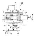
本発明の第1実施形態について図1を参照して説明する。図1に示すように、第1実施形態の液圧ブレーキ装置25は、マスタシリンダ26内に、先端の小径部27、中央の大径部28及び基端のロッド部29を有する段付のピストン30が摺動可能に嵌装されて、加圧室31、供給室32及び圧力加算室33の3室が形成されている。ロッド部29は、小径部27より大径、かつ、大径部28より小径で、マスタシリンダ26の外部へ延出された端部に、ブレーキペダル34が連結されている。ピストン30の小径部27の加圧室31に対する有効受圧面積Sa、大径部28の供給室32に対する有効受圧面積Sb及び大径部28の圧力加算室33に対する有効受圧面積Scの関係は、Sa>ScかつSb>Scとなっている。加圧室31内には、戻しばね35が設けられている。
【0018】
加圧室31は、リザーバポート36を介してリザーバRに接続されている。リザーバポート36は、ピストン30が非制動位置にあるとき開き、制動が開始されてピストン30が前進すると、小径部27によって閉じられるように配置されている。また、加圧室31は、管路37(第1の管路)を介してホイールシリンダ38に接続されている。
【0019】
圧力加算室33は、管路39(第2の管路)を介してホイールシリンダ38に接続されている。管路39には、比例電磁弁40(開閉弁)が設けられている。比例電磁弁40は、プッシュ型リニアソレノイドを備えたポペット構造の常開の電磁弁であって、通電電流に応じてその開度を調整できるようになっている。
【0020】
供給室32は、圧力制御弁42を介してポンプ41の吸込側に接続され、ポンプ41の吐出側は、管路39の圧力加算室33と比例電磁弁40との間に接続されている。ポンプ41は、通常は、停止されており、ブレーキペダル34の操作または後述の自動ブレーキの作動に連動して起動するようになっている。圧力制御弁42は、管路43(第3の管路)によって管路37に接続され、また、管路44によってリザーバRに接続されている。圧力制御弁42は、スプール式のパイロット型圧力制御弁であり、供給室32及びリザーバRの圧力を導入して、供給室32の圧力が、正圧の場合は、管路43を閉鎖して、供給室32側のブレーキ液をポンプ41によって管路39側へ吐出させ、供給室32の圧力が負圧の場合は、管路43をポンプ41の吸込側に連通させて、ポンプ41をアンロードすることにより、供給室32の圧力をほぼ0に保つようにしている(0に近づけるように調整している)。圧力制御弁42は、上記の機能を有するものであれば、他の形式のものでもよく、例えば、差圧検出ピストンを有するポペット形式のものとすることもできる。
【0021】
以上のように構成した、本実施形態の作用について、次に説明する。通常は、比例電磁弁40を全開とする。ブレーキペダル34が操作力Fで踏みこまれて、戻しばね35のばね力Fkに抗してピストン30が前進すると、小径部27によってリザーバポート36が閉じる。ポンプ41が起動すると、比例電磁弁40が開いているので、ポンプ41の吐出圧力によって、管路39及び管路37を介して、加圧室31、ホイールシリンダ38及び圧力加算室33が等しく加圧される。
【0022】
このとき、加圧室31の圧力をPa、供給室32の圧力をPb、圧力加算室33の圧力をPcとすると、ピストン30に作用する力のバランスから次式が成立つ。
F=Sa×Pa+Sb×Pb−Sc×Pc+Fk (2)
ここで、供給室32は、その圧力が正圧になると、圧力制御弁42が管路43を閉じるので、ポンプ23の吸込によって減圧され、その圧力がほぼ0になると、圧力制御弁42が管路43を吸込側に連通させてポンプ41をアンロードするので、その圧力がほぼ0となる。また、ポンプ41は、加圧室31及び圧力加算室33を等しく加圧する。しがって、(2)式において、Pb=0、Pa=Pcとすると、
Pa=(F−Fk)/(Sa−Sc)
となる。一方、ポンプ41を作動させず、ホイールシリンダ38をピストン30によって直接加圧する場合の加圧室31の圧力Pa´は、Pa=Pb=Pcから、
Pa´=(F−Fk)/(Sa+Sb−Sc)
であるから、倍力比αは、
α=Pa/Pa´=(Sa+Sb−Sc)/(Sa−Sc)
となり、倍力制御を行なうことができる。このとき、ブレーキペダル34への反力Fは、
F=(Sa−Sc)×Pa+Fk
となる。また、ホイールシリンダ38へのブレーキ液の供給量は、ピストン30のストロークをLとすると、
(Sa+Sb−Sc)×L
であり、Sa+Sb−Scは、ピストン30のロッド部29の断面積に等しい。なお、ポンプ41の故障等によって倍力機能が失われた場合にも、加圧室31、供給室32及び圧力加算室33の協働によって、上記圧力Pa´が得られるので、制動力を確保することができる。
【0023】
次に、自動ブレーキの作動について説明する。自動ブレーキとして作動させる場合は、ポンプ41を起動するとともに、比例電磁弁40を半閉状態にして、圧力加算室33を加圧する。圧力加算室33の圧力Pcが上昇して、Sc×Pc>Fkになると、ピストン30が前進して、リザーバポート36を閉じる。これ以後は、上記倍力制御時と同様、ポンプ41及び圧力制御弁42の作動によって、Pb=0となるから、加圧室31の圧力Paは、
Pa=(Sc×Pc−Fk)/Sa
となる。比例電磁弁40への通電電流を圧力加算室33と加圧室31との差圧
ΔP=Pc−Pa=(Sa/Sc−1)×Pa+Fk/Sc
に対応した電流値にすれば、目標のホイールシリンダ圧力Paが得られる。Sa>Scであるから、ΔPは、常に正であり、ホイールシリンダ圧力Paは、比例電磁弁40への通電電流の増加に対して、定数1/(Sa/Sc−1)で直線的に増大する。このとき、ホイールシリンダ38へのブレーキ液の供給量は、上記倍力制御時と同様である。
【0024】
自動ブレーキ作動時には、供給室32から圧力加算室33へブレーキ液を供給するので、上記倍力制御時と同様に制御するためには、Sb>Scであることが望ましいが、圧力制御弁42を供給室32の圧力Pbが0のとき、加圧室31側から供給室32側へブレーキ液が流れるように構成すれば、Sb<Scでも圧力加算室33を加圧することが可能となる。
【0025】
次に、本発明の第2実施形態について、図2を参照して説明する。第2実施形態は、上記第1実施形態に対して、マスタシリンダをタンデム化して2系統とし、各系統に2つのホイールシリンダを設けたものであるから、以下、上記第1実施形態と同様の部分については同一の符号を付して異なる部分についてのみ詳細に説明する。
【0026】
図2に示すように、第2実施形態の液圧ブレーキ装置45では、マスタシリンダ46は、セカンダリピストン47及びその戻しばね48が挿入されてタンデム化されて、第2加圧室49が形成されている。第2加圧室49は、リザーバポート50を介して、リザーバRに接続され、また、第2加圧室49は、管路51を介して、2つのホイールシリンダ52に接続されている。
【0027】
ピストン30は、大径部28の供給室32に対する有効受圧面積Sbと圧力加算室33に対する有効受圧面積Scとを等しくして、Sa+Sb−Sc=Saとなるようにしてある。また、セカンダリピストン47は、ピストン30(プライマリピストン)の小径部27と径を同一にしている。
【0028】
このように構成したことにより、加圧室31が加圧されると、セカンダリピストン47を介して第2加圧室49も同様に加圧されて、ホイールシリンダ52がホイールシリンダ38と同様に加圧されて制動力を発生させる。このとき、ピストン30の小径部27とセカンダリピストン47とを同径としたことにより、加圧室31と第2加圧室49との吐出量が等しくなる。また、シリンダ部の段差が少なくなり、加工及び組立を容易に行なうことができる。なお、プライマリ側とセカンダリ側で異なる吐出量が必要な場合には、Sb<Scとして、ロッド部29の径を大きくすることにより、プライマリ側の吐出量を大きくすることができる。
【0029】
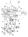
次に、本発明の第3実施形態について、図3を参照して説明する。なお、第3実施形態は、上記第1実施形態に対して、ホイールシリンダを2個設け、さらに、ABS(アンチロックブレーキシステム)を設けたものであるから、以下、上記第1実施形態と同様の部分については同一の符号を付して異なる部分についてのみ詳細に説明する。
【0030】
図3に示すように、第3実施形態の液圧ブレーキ装置53では、加圧室31に連通する管路37には、2つのホイールシリンダ38が接続されている。管路37には、それぞれのホイールシリンダ38に対して、増圧弁54(常開の電磁開閉弁)と、加圧室31側からホイールシリンダ側への流れのみを許容する逆止弁55とが並列に配置されている。また、各ホイールシリンダ38は、管路56によって減圧弁57(常閉の電磁開閉弁)を介して、アキュムレータ58に接続されており、アキュムレータ58は、逆止弁59を介してポンプ41の吸込側に接続されている。逆止弁59は、アキュムレータ58側からポンプ41側への流れのみを許容するものである。
【0031】
このように構成したことにより、上記第1実施形態のものと同様、倍力制御及び自動ブレーキ制御を行うことができる。
【0032】
また、ABSの作動は、ホイールシリンダ38によって発生した制動力が路面タイヤ間の摩擦力よりも大きくなり、タイヤがロックしたとき、常開の増圧弁54を閉じ、常閉の減圧弁57を開く。これにより、ホイールシリンダ38へのブレーキ液の供給が停止され、ホイールシリンダ38内の加圧されたブレーキ液がアキュムレータ58へ流出されて、ホイールシリンダ38の圧力が低下して、タイヤのロックが解消される。その後、減圧弁57を閉じ、増圧弁54を開くと、ポンプ41は運転されているので、アキュムレータ58に蓄えられたブレーキ液は、逆止弁59を介してポンプ41によって吐出されて、ホイールシリンダ38を再度加圧する。
【0033】
次に、本発明の第4実施形態について、図4を参照して説明する。なお、第4実施形態は、上記第2実施形態のものに、上記第3実施形態のものと同様のABSを組込んだものであるから、以下、上記第2及び第3実施形態に対して、同様の部分については同一の符号を付して異なる部分についてのみ詳細に説明する。
【0034】
図4に示すように、第4実施形態の液圧ブレーキ装置60では、第2加圧室49に連通する管路51には、それぞれのホイールシリンダ52に対して、増圧弁61(常開の電磁開閉弁)と、第2加圧室49側からホイールシリンダ52側への流れのみを許容する逆止弁62とが並列に配置されている。また、各ホイールシリンダ52は、管路63によって減圧弁64(常閉の電磁開閉弁)を介して、アキュムレータ65に接続されている。アキュムレータ65は、絞り66を介してリターン用のポンプ67の吸込側に接続されている。ポンプ67の吐出側は、逆止弁68を介して管路51に接続されている。逆止弁68は、ポンプ67側から管路51側への流れのみを許容するものである。ポンプ67には、ABS作動時にホイールシリンダ52を再加圧する際、アキュムレータ65の圧力がほぼ0になるように吐出量を制御する圧力制御弁69が設けられている。プライマリ側のポンプ41とセカンダリ側のポンプ67とは、共通のモータ70によって駆動される。絞り66及びプライマリ側の管路56に設けられた絞り71は、ABS作動時に、アキュムレータ58、65からポンプ41、67の吸込側へのブレーキ液の急激な移動を防止するためのものである。
【0035】
このように構成したことにより、上記第2及び第3実施形態と同様に、2系統のホイールシリンダにブレーキ液を供給して、倍力制御、自動ブレーキ制御及びアンチロックブレーキ制御を行なうことができる。
【0036】
次に、本発明の第5実施形態について、図5を参照して説明する。なお、第5実施形態は、上記第3実施形態の液圧ブレーキ装置を並列に配置して、2系統としたものであるから、上記第3実施形態のものと同様の部分については同一の符号付して異なる部分についてのみ詳細に説明する。
【0037】
図5に示すように、第5実施形態の液圧ブレーキ装置72では、上記第3実施形態と同様の2つのマスタシリンダ26を並列に配置し、それぞれのピストン30のロッド部29に、ガイド73によって進退動可能に案内されたレバー74を介してブレーキペダル34が連結されており、ブレーキペダル34の操作力Fが1/2ずつに分割されて、それぞれのピストン30に伝達されるようになっている。また、各系統のポンプ41は、共通のモータ75によって駆動されるようになっている。
【0038】
このように構成したことにより、2系統のホイールシリンダに対して、上記第3実施形態と同様、倍力制御、自動ブレーキ制御及びアンチロックブレーキ制御を行なうことができる。このとき、一方の系統が失陥した場合でも、他方の系統によって必要な制動力を確保することができる。
【0039】
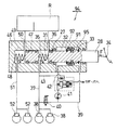
次に、本発明の第6実施形態について、図6を参照して説明する。なお、第6実施形態は、上記第1実施形態のピストンにアキュムレータを組込んだものであるから、図1に示す第1実施形態のものと同様の部分には同一の符号を付して異なる部分についてのみ詳細に説明する。
【0040】
図6に示すように、第6実施形態の液圧ブレーキ装置76では、ピストン30の小径部27にアキュムレータ77(蓄圧手段)が内蔵されている。アキュムレータ77は、小径部27内に形成されたシリンダボア78内に、フリーピストン79が摺動可能に嵌装され、フリーピストン79によってシリンダボア78内が油室78A、78Bの2室に画成されている。油室78Aは、油路80を介して供給室32に連通されており、油室78Bは、油路81および油路82を介してリザーバRに連通されている。フリーピストン79は、通常は、油室78B内に設けられた戻しばね83のばね力によって、シリンダボア78の油室78A側の端部に当接されている。
【0041】
このように構成したことにより、上記第1実施形態と同様、倍力制御および自動ブレーキ制御を行うことができる。
この場合、ポンプ41は、ブレーキペダル34の操作に連動して起動するため、ブレーキペダル34が踏込まれてからポンプ41の吐出量が必要な規定値に達するまでには、0.1ないし0.2秒程度の時間がかかる。このため、上記第1実施形態では、制動初期において、ポンプ41の吐出量が不足して、供給室32の圧力が0に保持されず、一時的に昇圧される。このとき、供給室32の圧力Pbが大径部28の有効受圧面積Sbに作用して、ピストン30に反力Pb×Sbが生じるため、ピストン30の移動量が不足して、加圧室31および圧力加算室33の昇圧が遅れるとともに、ブレーキペダル34の反力が増大してブレーキ操作感が悪化する。
【0042】
本実施形態の液圧ブレーキ装置76では、このとき、アキュムレータ77のフリーピストン79が後退して、供給室32内のブレーキ液が油室78Aに流入することによって圧力の上昇が緩和される。フリーピストン79の背面側の油室78Bは、リザーバRに連通されているので、供給室32の圧力は、リザーバRとほぼ同圧に保持されて、ピストン30の反力の増大を軽減することができ、ブレーキ操作感を改善することができる。
【0043】
その後、ポンプ41の吐出量が必要な規定値に達すると、供給室32のブレーキ液がポンプ41によって、供給室31および圧力加算室33に移送されて、アキュムレータ77のフリーピストン79が原位置に復帰し、倍力制御の圧力バランス状態、すなわち、次式
Pa=(F−Fk)/(Sa−Sc)
が成立つ状態となる。このようにして、制動初期におけるブレーキペダル34への反力の増大を軽減してブレーキ操作感を向上させることができる。また、アキュムレータ77をピストン37に内蔵したことにより、マスタシリンダ26の小型化を図ることができる。
【0044】
一方、自動ブレーキ作動時には、ポンプ41の起動によって、供給室32が減圧されても、フリーピストン79がシリンダボア78の端部に当接して移動せず、アキュムレータ77は作動しないので、上記第1実施例と同様に自動ブレーキ制御を実行することができる。
【0045】
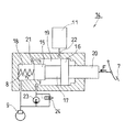
次に、本発明の第7実施形態について、図7を参照して説明する。なお、第7実施形態の液圧ブレーキ装置は、上記第6実施形態に対して、ピストンに内蔵されたアキュムレータの構造が異なる以外は、概して同様の構造であるから、ピストンのみを図示し、図6に示す第6実施形態と同様の部分には同一の符号を付して、異なる部分についてのみ詳細に説明する。
【0046】
図7に示すように、第7実施形態に係る液圧ブレーキ装置のピストン30に内蔵されたアキュムレータ84(蓄圧手段)は、大径部28を通して形成されたシリンダボア85内に、フリーピストン86が摺動可能に嵌装されており、フリーピストン86によってシリンダボア85内が油室85A、85Bの2室に画成されている。油室85Aは、油路87を介して供給室32に連通されており、油室85Bは、油路88を介して圧力加算室33に連通されている。フリーピストン86は、油室85B内に設けられた戻しばね89のばね力によって、通常、シリンダボア85の油室85A側の端部に当接されている。
【0047】
このように構成したことにより、制動初期において、供給室32が加圧されて加圧室31および圧力加算室33よりも高圧になると、アキュムレータ84のフリーピストン86が後退して、供給室32内のブレーキ液が油室85Aに流入することによって圧力の上昇が緩和される。フリーピストン86の背面側の油室85Bは、圧力加算室33(加圧室33と同圧)に連通されているので、供給室32の圧力は、加圧室31および圧力加算室33とほぼ同圧に維持されて、ピストン30への反力の増大を軽減することができ、上記第6実施形態と同様、ブレーキ操作感を改善することができる。その後、ポンプの吐出量が必要な規定値に達すると、上記第6実施形態と同様、供給室32が減圧されて、所定の圧力バランスの下で倍力制御を実行することができる。
【0048】
この場合、供給室32の圧力は、加圧室31および圧力加算室33とほぼ同圧となり、リザーバRと同圧となる上記第6実施形態の場合よりも高圧となるので、上記第6実施形態よりも、ややブレーキ反力の軽減効果が小さくなる。
【0049】
自動ブレーキ作動時には、ポンプ41の起動によって、供給室32が減圧されても、フリーピストン86がシリンダボア85の端部に当接して移動せず、アキュムレータ84は作動しないので、上記第6実施例と同様に自動ブレーキ制御を実行することができる。
【0050】
なお、上記第6および第7本実施形態では、アキュムレータをピストンに内蔵したものについて説明しているが、このほか、マスシリンダの外部にアキュムレータを配置して、供給室、リザーバおよび圧力加算室に接続するように構成することもできる。
【0051】
次に、本発明の第8実施形態について、図8を参照して説明する。なお、第8実施形態は、上記第1実施形態のピストンの大径部に、上記第7実施形態のアキュムレータとしての機能を組込んだものであるから、上記第1および第7実施形態のものと同様の部分には同一の符号を付して、異なる部分についてのみ詳細に説明する。
【0052】
第8実施形態の液圧ブレーキ装置90では、供給室32と圧力加算室33とを画成するピストン30の大径部91(ピストン部)は、小径部27を摺動可能に挿通させた環状部材からなり、小径部27およびロッド部29に対して、軸方向に沿って移動可能に支持されている。ピストン30の小径部27には、大径部91に当接するストッパ92が取付けられており、大径部28は、大径部28とロッド部29の肩部との間に設けられた皿ばね93のばね力によって、通常、ストッパ92に当接されている。
【0053】
このように構成したことにより、制動初期において、供給室30が加圧されると、大径部91は、皿ばね93のばね力に抗して後退することにより、アキュムレータとして作用して供給室30の圧力の上昇を緩和する。これにより、上記第7実施形態と同様の作用、効果を奏することができる。
【0054】
次に、本発明の第9実施形態について、図9を参照して説明する。図9に示すように、第9実施形態の液圧ブレーキ装置94は、上記第2実施形態のタンデム型の液圧ブレーキ装置において、ピストンの大径部に、上記第8実施形態と同様のアキュムレータとしての機能を組込んだものである。図9においては、上記第2および第8実施形態のものと同様の部分には同一の符号を付してある。なお、上記第8実施形態では、大径部91を付勢するばねとして、皿ばね93を用いているのに対して、本実施形態では、コイルばね95を使用している。
【0055】
このように構成したことにより、上記第2実施形態のタンデム型の液圧ブレーキ装置において、上記第8実施形態と同様の作用、効果を奏することができる。
【0056】
【発明の効果】
以上詳述したように、本発明の液圧ブレーキ装置によれば、ピストンに対する操作力に応じてポンプによってホイールシリンダに接続された加圧室及び圧力加算室を加圧して倍力制御を行うことができ、このとき、ピストンの加圧室に対する有効受圧面積と圧力加算室に対する有効受圧面積との差によって、倍力比を決定することができる。
また、開閉弁を閉じることにより、ポンプの加圧によって、圧力加算室の圧力を加圧室の圧力よりも高くすることができ、これにより、ピストンを前進させて自動ブレーキを作動させることができる。
【図面の簡単な説明】
【図1】本発明の第1実施形態に係る液圧ブレーキ装置を示す回路図である。
【図2】本発明の第2実施形態に係る液圧ブレーキ装置を示す回路図である。
【図3】本発明の第3実施形態に係る液圧ブレーキ装置を示す回路図である。
【図4】本発明の第4実施形態に係る液圧ブレーキ装置を示す回路図である。
【図5】本発明の第5実施形態に係る液圧ブレーキ装置を示す回路図である。
【図6】本発明の第6実施形態に係る液圧ブレーキ装置を示す回路図である。
【図7】本発明の第7実施形態に係る液圧ブレーキ装置のピストンの概略構成を示す縦断面図である。
【図8】本発明の第8実施形態に係る液圧ブレーキ装置を示す回路図である。
【図9】本発明の第9実施形態に係る液圧ブレーキ装置を示す回路図である。
【図10】自動ブレーキ機能を有する従来の液圧ブレーキ装置を示す回路図である。
【図11】倍力制御機能を有する従来の液圧ブレーキ装置を示す回路図である。
【符号の説明】
25,45,53,60,72,76,90,94 液圧ブレーキ装置
26 マスタシリンダ
30 ピストン
31 加圧室
32 供給室
33 圧力加算室
38,52 ホイールシリンダ
41 ポンプ
42 圧力制御弁
40 比例電磁弁(開閉弁)
77,84 アキュムレータ(蓄圧手段)
91 大径部(ピストン部)
R リザーバ[0001]
[Industrial application fields]
The present invention relates to a hydraulic brake device that enables boost control and automatic brake control.
[0002]
[Prior art]
About conventional hydraulic brake equipment for automobilesTenAnd figure11Will be described with reference to FIG. FigureTo 10The hydraulic brake device 1 shown is an example in which an automatic brake operation function is provided with the simplest configuration. FigureTen, A large-
[0003]
The pressurizing
[0004]
Next, the operation of the hydraulic brake device 1 will be described. In the case of operating force only by a normal driver, the
Pa= (F−Fk) / Sa
It becomes.
[0005]
In the case of automatic brake control without operation by the driver, the
Pa= (Sc× Pc−Fk) / Sa
It becomes.
[0006]
If the driver's operating force and the automatic braking operation force act simultaneously, add these,
Pa= (F + Sc× Pc−Fk) / Sa
It can be. Alternatively, the pressure in the
[0007]
In addition, the pressure in both the pressurizing
F = Sa× Pa−Sc× Pc+ Fk
To calculate the operating force F, and the boost ratio is α,
Pa= Α x F / Sa
The discharge pressure of the
[0008]
However, when performing boost control in this way, it is necessary to use two expensive pressure sensors, and the operating force F is calculated based on the outputs of the two pressure sensors, so accuracy can be improved. With the problem of being difficult.
[0009]
On the other hand, the hydraulic brake device for automobiles shown in FIG. 11 is an example that enables boost control with a simple structure. Note that portions similar to those illustrated in FIG. 10 are described with the same reference numerals. Referring to FIG. 11, a
[0010]
The pressurizing
[0011]
Next, the operation of the
[0012]
As the
F = Sa× Pa+ Sb× Pb+ Fk ▲ 1 ▼
[0013]
Here, in the
Pa= (F−Fk) / Sa
It becomes. On the other hand, the pressure P in the pressurizing
Pa´ = (F−Fk) / (Sa+ Sb)
Therefore, the boost ratio α is
α = Pa/ Pa´ = (Sa+ Sb) / Sa
Thus, boost control can be performed. Note that the amount of brake fluid supplied to the
(Sa+ Sb) × L
It is. A brake system that performs boost control in this way is described, for example, in German Patent No. 19716404.
[0014]
[Problems to be solved by the invention]
However, the figure11 toIn the conventional example shown, the pressurizing
[0015]
The present invention has been made in view of the above points, and an object thereof is to provide a hydraulic brake device capable of performing boost control and automatic brake control with a simple structure.
[0016]
[Means for Solving the Problems]
To solve the above problem,The present inventionThe hydraulic brake device ofA stepped piston having a small-diameter portion and a large-diameter portion, a pressurizing chamber that is pressurized by the small-diameter portion by the advancement of the piston and connected to a wheel cylinder through a first conduit, A master cylinder having a supply chamber pressurized by a diameter portion, and a pressure addition chamber formed on the piston retreat side of the large diameter portion and connected to the wheel cylinder via a second pipe line;
An on-off valve provided in the second pipeline;
A pump having a suction side connected to the supply chamber and a discharge side connected between the pressure adding chamber of the second pipe line and the on-off valve;
Provided between the suction side of the pump and a third pipe connected to the first pipe, and communicates the suction side of the pump and the third pipe based on the pressure in the supply chamber A pressure control valve for shutting off,
An effective pressure receiving area of the piston with respect to the pressurizing chamber is larger than an effective pressure receiving area with respect to the pressure adding chamber;
The pressure control valve closes the third conduit when the pressure in the supply chamber is positive, and connects the third conduit to the suction side of the pump when the pressure in the supply chamber is negative. Communicate with
The pump is configured to reduce the pressure of the supply chamber, which becomes positive pressure as the piston moves forward, to approach 0 by suction..
With this configuration, it is possible to perform boost control by pressurizing the pressurizing chamber and the pressure adding chamber connected to the wheel cylinder by a pump according to the operating force on the piston. The boost ratio is determined by the difference between the effective pressure receiving area for the chamber and the effective pressure receiving area for the pressure adding chamber.Also,When the on-off valve is closed, the pressure in the pressure adding chamber becomes higher than the pressure in the pressurizing chamber due to the pressurization of the pump, and the piston moves forward and the automatic brake operates..
[0017]
DETAILED DESCRIPTION OF THE INVENTION
Hereinafter, embodiments of the present invention will be described in detail with reference to the drawings.
A first embodiment of the present invention will be described with reference to FIG. As shown in FIG. 1, the
[0018]
The pressurizing
[0019]
The
[0020]
The
[0021]
Next, the operation of the present embodiment configured as described above will be described. Normally, the
[0022]
At this time, the pressure in the pressurizing
F = Sa× Pa+ Sb× Pb−Sc× Pc+ Fk (2)
Here, the
Pa= (F−Fk) / (Sa−Sc)
It becomes. On the other hand, pump 41ThePressure P of the
Pa´ = (F−Fk) / (Sa+ Sb−Sc)
Therefore, the boost ratio α is
α = Pa/ Pa´ = (Sa+ Sb−Sc) / (Sa−Sc)
Thus, boost control can be performed. At this time, the reaction force F to the
F = (Sa−Sc) × Pa+ Fk
It becomes. Also, the amount of brake fluid supplied to the
(Sa+ Sb−Sc) × L
And Sa+ Sb−ScIs equal to the cross-sectional area of the
[0023]
Next, the operation of the automatic brake will be described. When operating as an automatic brake, the
Pa= (Sc× Pc−Fk) / Sa
It becomes. The differential current between
ΔP = Pc−Pa= (Sa/ Sc−1) × Pa+ Fk/ Sc
If the current value corresponds to the target wheel cylinder pressure PaIs obtained. Sa> ScΔP is always positive and the wheel cylinder pressure PaIs a constant of 1 / (S for the increase in the current flowing to the proportional solenoid valve 40.a/ Sc-1) linearly increases. At this time, the amount of brake fluid supplied to the
[0024]
Since brake fluid is supplied from the
[0025]
Next, a second embodiment of the present invention will be described with reference to FIG. In the second embodiment, the master cylinder is tandemd into two systems with respect to the first embodiment, and two wheel cylinders are provided in each system. Henceforth, the same as the first embodiment described above. The parts are denoted by the same reference numerals, and only different parts will be described in detail.
[0026]
As shown in FIG. 2, in the
[0027]
The
[0028]
With this configuration, when the pressurizing
[0029]
Next, a third embodiment of the present invention will be described with reference to FIG. In addition, since the third embodiment is provided with two wheel cylinders and further provided with an ABS (anti-lock brake system) with respect to the first embodiment, the same as the first embodiment below. These parts are denoted by the same reference numerals and only different parts will be described in detail.
[0030]
As shown in FIG. 3, in the
[0031]
With this configuration, boost control and automatic brake control can be performed as in the first embodiment.
[0032]
Further, when the ABS is activated, when the braking force generated by the
[0033]
Next, a fourth embodiment of the present invention will be described with reference to FIG. In the fourth embodiment, since the same ABS as that of the third embodiment is incorporated in the second embodiment, the following will be described with respect to the second and third embodiments. The same parts are denoted by the same reference numerals, and only different parts will be described in detail.
[0034]
As shown in FIG. 4, in the
[0035]
With this configuration, as in the second and third embodiments, brake fluid can be supplied to the two wheel cylinders to perform boost control, automatic brake control, and antilock brake control. .
[0036]
Next, a fifth embodiment of the present invention will be described with reference to FIG. In the fifth embodiment, the hydraulic brake device of the third embodiment is arranged in parallel to form two systems, so the same reference numerals are used for the same parts as those of the third embodiment. Only the different parts will be described in detail.
[0037]
As shown in FIG. 5, in the
[0038]
With this configuration, it is possible to perform boost control, automatic brake control, and antilock brake control for the two wheel cylinders as in the third embodiment. At this time, even when one of the systems fails, the necessary braking force can be ensured by the other system.
[0039]
Next, a sixth embodiment of the present invention will be described with reference to FIG. In the sixth embodiment, since the accumulator is incorporated in the piston of the first embodiment, parts similar to those of the first embodiment shown in FIG. Only the part will be described in detail.
[0040]
As shown in FIG. 6, in the
[0041]
With this configuration, boost control and automatic brake control can be performed as in the first embodiment.
In this case, since the
[0042]
In the
[0043]
Thereafter, when the discharge amount of the
Pa= (F−Fk) / (Sa−Sc)
Is established. In this way, it is possible to improve the feeling of brake operation by reducing an increase in the reaction force to the
[0044]
On the other hand, when the automatic brake is activated, even if the
[0045]
Next, a seventh embodiment of the present invention will be described with reference to FIG. The hydraulic brake device according to the seventh embodiment is generally similar to the sixth embodiment except that the structure of the accumulator built in the piston is different. The same parts as those in the sixth embodiment shown in FIG. 6 are denoted by the same reference numerals, and only different parts will be described in detail.
[0046]
As shown in FIG. 7, the accumulator 84 (pressure accumulating means) built in the
[0047]
With this configuration, when the
[0048]
In this case, the pressure in the
[0049]
When the automatic brake is activated, even if the
[0050]
In the sixth and seventh embodiments described above, the accumulator is incorporated in the piston. However, in addition to this, an accumulator is arranged outside the mass cylinder to provide the supply chamber, the reservoir, and the pressure adding chamber. It can also be configured to connect.
[0051]
Next, an eighth embodiment of the present invention will be described with reference to FIG. In the eighth embodiment, since the function of the accumulator of the seventh embodiment is incorporated in the large-diameter portion of the piston of the first embodiment, the eighth embodiment is the same as that of the first and seventh embodiments. The same reference numerals are given to the same parts, and only different parts will be described in detail.
[0052]
In the
[0053]
With this configuration, when the
[0054]
Next, a ninth embodiment of the present invention will be described with reference to FIG. As shown in FIG. 9, the
[0055]
With this configuration, in the tandem hydraulic brake device of the second embodiment, the same operations and effects as those of the eighth embodiment can be achieved.
[0056]
【The invention's effect】
As detailed above,The present inventionAccording to this hydraulic brake device, it is possible to perform boost control by pressurizing the pressurizing chamber and the pressure adding chamber connected to the wheel cylinder by a pump according to the operating force on the piston. The boost ratio can be determined by the difference between the effective pressure receiving area for the pressure chamber and the effective pressure receiving area for the pressure adding chamber.
Also,By closing the on-off valve, the pressure in the pressure adding chamber can be made higher than the pressure in the pressurizing chamber by pressurizing the pump, and thus the piston can be advanced to operate the automatic brake..
[Brief description of the drawings]
FIG. 1 is a circuit diagram showing a hydraulic brake device according to a first embodiment of the present invention.
FIG. 2 is a circuit diagram showing a hydraulic brake device according to a second embodiment of the present invention.
FIG. 3 is a circuit diagram showing a hydraulic brake device according to a third embodiment of the present invention.
FIG. 4 is a circuit diagram showing a hydraulic brake device according to a fourth embodiment of the present invention.
FIG. 5 is a circuit diagram showing a hydraulic brake device according to a fifth embodiment of the present invention.
FIG. 6 is a circuit diagram showing a hydraulic brake device according to a sixth embodiment of the present invention.
FIG. 7 is a longitudinal sectional view showing a schematic configuration of a piston of a hydraulic brake device according to a seventh embodiment of the present invention.
FIG. 8 is a circuit diagram showing a hydraulic brake device according to an eighth embodiment of the present invention.
FIG. 9 is a circuit diagram showing a hydraulic brake device according to a ninth embodiment of the present invention.
FIG. 10 is a circuit diagram showing a conventional hydraulic brake device having an automatic brake function.
FIG. 11 is a circuit diagram showing a conventional hydraulic brake device having a boost control function.
[Explanation of symbols]
25,45,53,60,72,76,90,94 Hydraulic brake device
26 Master cylinder
30 pistons
31 Pressurization chamber
32 Supply room
33 Pressure chamber
38,52 Wheel cylinder
41 pump
42 Pressure control valve
40 Proportional solenoid valve (open / close valve)
77,84 Accumulator (accumulation means)
91 Large diameter part (piston part)
R reservoir
Claims (3)
前記第2の管路に設けられる開閉弁と、An on-off valve provided in the second pipeline;
吸込側が前記供給室に接続され、吐出側が前記第2の管路の前記圧力加算室と前記開閉弁との間に接続されるポンプと、A pump having a suction side connected to the supply chamber and a discharge side connected between the pressure adding chamber of the second pipe line and the on-off valve;
該ポンプの吸込側と前記第1の管路に接続する第3の管路との間に設けられ、前記供給室の圧力に基づいて前記ポンプの吸込側と前記第3の管路とを連通、遮断する圧力制御弁と、を備え、Provided between the suction side of the pump and a third pipe connected to the first pipe, and communicates the suction side of the pump and the third pipe based on the pressure in the supply chamber A pressure control valve for shutting off,
前記ピストンの前記加圧室に対する有効受圧面積を前記圧力加算室に対する有効受圧面積より大きくし、An effective pressure receiving area of the piston with respect to the pressurizing chamber is larger than an effective pressure receiving area with respect to the pressure adding chamber;
前記圧力制御弁は、前記供給室の圧力が正圧のときに前記第3の管路を閉鎖し、前記供給室の圧力が負圧のときに前記第3の管路を前記ポンプの吸込側に連通させ、The pressure control valve closes the third conduit when the pressure in the supply chamber is positive, and connects the third conduit to the suction side of the pump when the pressure in the supply chamber is negative. Communicate with
前記ポンプは、吸込により、前記ピストンの前進に伴って正圧になる前記供給室の圧力を0に近づけるように減圧することを特徴とする液圧ブレーキ装置。The hydraulic brake device according to claim 1, wherein the pump reduces the pressure of the supply chamber, which becomes positive pressure as the piston moves forward, to approach 0 by suction.
Priority Applications (1)
| Application Number | Priority Date | Filing Date | Title |
|---|---|---|---|
| JP2001024224A JP4512933B2 (en) | 2000-08-31 | 2001-01-31 | Hydraulic brake device |
Applications Claiming Priority (3)
| Application Number | Priority Date | Filing Date | Title |
|---|---|---|---|
| JP2000264165 | 2000-08-31 | ||
| JP2000-264165 | 2000-08-31 | ||
| JP2001024224A JP4512933B2 (en) | 2000-08-31 | 2001-01-31 | Hydraulic brake device |
Publications (3)
| Publication Number | Publication Date |
|---|---|
| JP2002145043A JP2002145043A (en) | 2002-05-22 |
| JP2002145043A5 JP2002145043A5 (en) | 2008-02-14 |
| JP4512933B2 true JP4512933B2 (en) | 2010-07-28 |
Family
ID=26599012
Family Applications (1)
| Application Number | Title | Priority Date | Filing Date |
|---|---|---|---|
| JP2001024224A Expired - Fee Related JP4512933B2 (en) | 2000-08-31 | 2001-01-31 | Hydraulic brake device |
Country Status (1)
| Country | Link |
|---|---|
| JP (1) | JP4512933B2 (en) |
Families Citing this family (1)
| Publication number | Priority date | Publication date | Assignee | Title |
|---|---|---|---|---|
| JP4890378B2 (en) * | 2007-07-31 | 2012-03-07 | 日立オートモティブシステムズ株式会社 | Brake device |
Citations (2)
| Publication number | Priority date | Publication date | Assignee | Title |
|---|---|---|---|---|
| JPS61207264A (en) * | 1985-03-11 | 1986-09-13 | Aisin Seiki Co Ltd | Liquid pressure booster |
| DE19716404C1 (en) * | 1997-04-18 | 1998-10-29 | Lucas Automotive Gmbh | Hydraulic brake system for motor vehicles |
-
2001
- 2001-01-31 JP JP2001024224A patent/JP4512933B2/en not_active Expired - Fee Related
Patent Citations (2)
| Publication number | Priority date | Publication date | Assignee | Title |
|---|---|---|---|---|
| JPS61207264A (en) * | 1985-03-11 | 1986-09-13 | Aisin Seiki Co Ltd | Liquid pressure booster |
| DE19716404C1 (en) * | 1997-04-18 | 1998-10-29 | Lucas Automotive Gmbh | Hydraulic brake system for motor vehicles |
Also Published As
| Publication number | Publication date |
|---|---|
| JP2002145043A (en) | 2002-05-22 |
Similar Documents
| Publication | Publication Date | Title |
|---|---|---|
| US9221443B2 (en) | Slip control boost braking system | |
| EP1755933B1 (en) | Slip control boost braking system | |
| US6945610B1 (en) | Hydraulic braking system wherein electrically controllable assisting drive force is applied to master cylinder piston upon brake pedal operation | |
| JPS61171654A (en) | Hydraulic brake gear | |
| KR20080026202A (en) | Vehicular brake system | |
| JP2013514933A (en) | Hydraulic vehicle brake device | |
| US20060220451A1 (en) | Electrohydraulic brake system for motor vehicles | |
| JP3582155B2 (en) | Vehicle brake control device | |
| JPS6099755A (en) | Hydric brake system functioning as control of non-slip in combination | |
| US6685280B1 (en) | Vehicle braking system and vehicle braking device | |
| US6386842B1 (en) | Low cost, single stroke, electromagnetic pre-charge pump for controlled brake systems | |
| US6644760B2 (en) | Hydraulic pressure control device and vehicle brake device using the same | |
| US7201455B2 (en) | Hydraulic brake system and method for controlling same | |
| CN112512876B (en) | Brake control device | |
| US5897175A (en) | Brake pressure control system for a vehicle | |
| CN107531219B (en) | Brake device for vehicle | |
| JP4375139B2 (en) | Brake fluid pressure generator and brake system | |
| JP4512933B2 (en) | Hydraulic brake device | |
| JP2019059409A (en) | Vehicular brake device | |
| JP3577790B2 (en) | Vehicle brake control device | |
| JP3069993B2 (en) | Lock prevention device for spool valve in servo valve | |
| JPH10258726A (en) | Brake fluid pressure controller | |
| JPH08258701A (en) | Brake control system for vehicle | |
| JPH04287752A (en) | Antiskid hydraulic control device | |
| JPH0194057A (en) | Antilock brake |
Legal Events
| Date | Code | Title | Description |
|---|---|---|---|
| A711 | Notification of change in applicant |
Free format text: JAPANESE INTERMEDIATE CODE: A712 Effective date: 20041129 |
|
| A521 | Written amendment |
Free format text: JAPANESE INTERMEDIATE CODE: A523 Effective date: 20071226 |
|
| A621 | Written request for application examination |
Free format text: JAPANESE INTERMEDIATE CODE: A621 Effective date: 20071226 |
|
| A711 | Notification of change in applicant |
Free format text: JAPANESE INTERMEDIATE CODE: A712 Effective date: 20090902 |
|
| RD03 | Notification of appointment of power of attorney |
Free format text: JAPANESE INTERMEDIATE CODE: A7423 Effective date: 20090902 |
|
| A521 | Written amendment |
Free format text: JAPANESE INTERMEDIATE CODE: A523 Effective date: 20090904 |
|
| A131 | Notification of reasons for refusal |
Free format text: JAPANESE INTERMEDIATE CODE: A131 Effective date: 20100120 |
|
| A977 | Report on retrieval |
Free format text: JAPANESE INTERMEDIATE CODE: A971007 Effective date: 20100121 |
|
| A521 | Written amendment |
Free format text: JAPANESE INTERMEDIATE CODE: A523 Effective date: 20100323 |
|
| TRDD | Decision of grant or rejection written | ||
| A01 | Written decision to grant a patent or to grant a registration (utility model) |
Free format text: JAPANESE INTERMEDIATE CODE: A01 Effective date: 20100421 |
|
| A01 | Written decision to grant a patent or to grant a registration (utility model) |
Free format text: JAPANESE INTERMEDIATE CODE: A01 |
|
| A61 | First payment of annual fees (during grant procedure) |
Free format text: JAPANESE INTERMEDIATE CODE: A61 Effective date: 20100427 |
|
| R150 | Certificate of patent or registration of utility model |
Free format text: JAPANESE INTERMEDIATE CODE: R150 |
|
| FPAY | Renewal fee payment (event date is renewal date of database) |
Free format text: PAYMENT UNTIL: 20130521 Year of fee payment: 3 |
|
| FPAY | Renewal fee payment (event date is renewal date of database) |
Free format text: PAYMENT UNTIL: 20130521 Year of fee payment: 3 |
|
| FPAY | Renewal fee payment (event date is renewal date of database) |
Free format text: PAYMENT UNTIL: 20140521 Year of fee payment: 4 |
|
| LAPS | Cancellation because of no payment of annual fees |