EP0950148B1 - Verfahren und vorrichtung zur steuerung der antriebseinheit eines fahrzeugs - Google Patents
Verfahren und vorrichtung zur steuerung der antriebseinheit eines fahrzeugs Download PDFInfo
- Publication number
- EP0950148B1 EP0950148B1 EP98941245A EP98941245A EP0950148B1 EP 0950148 B1 EP0950148 B1 EP 0950148B1 EP 98941245 A EP98941245 A EP 98941245A EP 98941245 A EP98941245 A EP 98941245A EP 0950148 B1 EP0950148 B1 EP 0950148B1
- Authority
- EP
- European Patent Office
- Prior art keywords
- torque
- function
- drive unit
- driver
- maximum permitted
- Prior art date
- Legal status (The legal status is an assumption and is not a legal conclusion. Google has not performed a legal analysis and makes no representation as to the accuracy of the status listed.)
- Expired - Lifetime
Links
- 238000000034 method Methods 0.000 title claims abstract description 11
- 230000001419 dependent effect Effects 0.000 claims description 10
- 241001484259 Lacuna Species 0.000 claims 2
- 238000012544 monitoring process Methods 0.000 description 15
- 239000000446 fuel Substances 0.000 description 8
- 230000015572 biosynthetic process Effects 0.000 description 3
- 238000002485 combustion reaction Methods 0.000 description 3
- 230000008859 change Effects 0.000 description 2
- 238000010586 diagram Methods 0.000 description 2
- 230000004044 response Effects 0.000 description 2
- 230000001960 triggered effect Effects 0.000 description 2
- 230000005540 biological transmission Effects 0.000 description 1
- 238000006243 chemical reaction Methods 0.000 description 1
- 238000004891 communication Methods 0.000 description 1
- 230000007423 decrease Effects 0.000 description 1
- 238000001514 detection method Methods 0.000 description 1
- 238000006073 displacement reaction Methods 0.000 description 1
- 230000009467 reduction Effects 0.000 description 1
- 239000007787 solid Substances 0.000 description 1
Images

Classifications
-
- F—MECHANICAL ENGINEERING; LIGHTING; HEATING; WEAPONS; BLASTING
- F02—COMBUSTION ENGINES; HOT-GAS OR COMBUSTION-PRODUCT ENGINE PLANTS
- F02D—CONTROLLING COMBUSTION ENGINES
- F02D41/00—Electrical control of supply of combustible mixture or its constituents
- F02D41/02—Circuit arrangements for generating control signals
- F02D41/14—Introducing closed-loop corrections
-
- F—MECHANICAL ENGINEERING; LIGHTING; HEATING; WEAPONS; BLASTING
- F02—COMBUSTION ENGINES; HOT-GAS OR COMBUSTION-PRODUCT ENGINE PLANTS
- F02D—CONTROLLING COMBUSTION ENGINES
- F02D31/00—Use of speed-sensing governors to control combustion engines, not otherwise provided for
- F02D31/001—Electric control of rotation speed
- F02D31/007—Electric control of rotation speed controlling fuel supply
- F02D31/009—Electric control of rotation speed controlling fuel supply for maximum speed control
-
- F—MECHANICAL ENGINEERING; LIGHTING; HEATING; WEAPONS; BLASTING
- F02—COMBUSTION ENGINES; HOT-GAS OR COMBUSTION-PRODUCT ENGINE PLANTS
- F02D—CONTROLLING COMBUSTION ENGINES
- F02D11/00—Arrangements for, or adaptations to, non-automatic engine control initiation means, e.g. operator initiated
- F02D11/06—Arrangements for, or adaptations to, non-automatic engine control initiation means, e.g. operator initiated characterised by non-mechanical control linkages, e.g. fluid control linkages or by control linkages with power drive or assistance
- F02D11/10—Arrangements for, or adaptations to, non-automatic engine control initiation means, e.g. operator initiated characterised by non-mechanical control linkages, e.g. fluid control linkages or by control linkages with power drive or assistance of the electric type
- F02D11/105—Arrangements for, or adaptations to, non-automatic engine control initiation means, e.g. operator initiated characterised by non-mechanical control linkages, e.g. fluid control linkages or by control linkages with power drive or assistance of the electric type characterised by the function converting demand to actuation, e.g. a map indicating relations between an accelerator pedal position and throttle valve opening or target engine torque
-
- F—MECHANICAL ENGINEERING; LIGHTING; HEATING; WEAPONS; BLASTING
- F02—COMBUSTION ENGINES; HOT-GAS OR COMBUSTION-PRODUCT ENGINE PLANTS
- F02D—CONTROLLING COMBUSTION ENGINES
- F02D2250/00—Engine control related to specific problems or objectives
- F02D2250/18—Control of the engine output torque
-
- F—MECHANICAL ENGINEERING; LIGHTING; HEATING; WEAPONS; BLASTING
- F02—COMBUSTION ENGINES; HOT-GAS OR COMBUSTION-PRODUCT ENGINE PLANTS
- F02D—CONTROLLING COMBUSTION ENGINES
- F02D2250/00—Engine control related to specific problems or objectives
- F02D2250/18—Control of the engine output torque
- F02D2250/26—Control of the engine output torque by applying a torque limit
-
- F—MECHANICAL ENGINEERING; LIGHTING; HEATING; WEAPONS; BLASTING
- F02—COMBUSTION ENGINES; HOT-GAS OR COMBUSTION-PRODUCT ENGINE PLANTS
- F02D—CONTROLLING COMBUSTION ENGINES
- F02D41/00—Electrical control of supply of combustible mixture or its constituents
- F02D41/02—Circuit arrangements for generating control signals
- F02D41/04—Introducing corrections for particular operating conditions
- F02D41/06—Introducing corrections for particular operating conditions for engine starting or warming up
Definitions
- the invention relates to a method and a device to control the drive unit of a motor vehicle according to the preambles of the independent claims.
- DE-A 195 36 038 describes a method and a device to control the drive unit of a motor vehicle known, in which a torque of the drive unit is dependent controlled by a setpoint for this torque becomes.
- a torque of the drive unit is dependent controlled by a setpoint for this torque becomes.
- a maximum permissible torque Drive unit formed, this with an actual Drive unit torque compared and fault response measures initiated when the actual torque the drive unit exceeds the maximum permissible torque.
- the maximum permissible torque depends on the target torque value educated. This in turn is based on the Position of a control element that can be actuated by the driver, for example of an accelerator pedal, or depending on that of others Control systems or functions predetermined target torque, for example depending on a target torque an engine drag torque control and / or an idle speed control calculated.
- the maximum allowable torque becomes dependent on the target torque value using a characteristic curve or a map is formed.
- a consideration of Tolerances of the drive unit, which e.g. through internal friction is not described. This is also permissible Moment depending on the driver's desired torque, so that at a theoretically conceivable error in the calculation of this Moments the permissible torque is also incorrect.
- Torque base Monitoring a control of a drive unit Torque base is significantly improved because the Formation of the maximum permissible torque, which of the monitoring underlying, tolerances are taken into account, too when external intervention works.
- driver's desired torque is not in the calculation of the permissible torque is received.
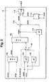
- FIG. 1 is a control device for a multi-cylinder Internal combustion engine 10 shown.
- the control device comprises an electronic control unit 12, which consists of at least a microcomputer 14, an input 16 and one Output unit 18 exists.
- Input unit 16, output unit 18 and the at least one microcomputer 14 are via one Communication bus 20 for mutual data exchange with one another connected.
- the input unit 16 are the input lines 22, 24, 28 and 30 fed.
- the line 22 comes a measuring device 32 for detecting the pedal position, the line 24 from a measuring device 34 for detection the engine speed, the line 28 from a measuring device 38 for detecting a motor load representative Size and line 30 of at least one other Control device 40, for example a control device for traction control for transmission control, for engine drag torque control, for driving speed control, etc.
- the quantity representing the engine load are air mass, air flow meter depending on the embodiment or pressure sensors to record the intake manifold pressure intended.
- the Control unit other sizes essential for engine control like engine temperature, driving speed, the time after Start, intake air temperature, etc.
- An output line 42 is connected to the output unit 18, on an electrically operated throttle valve 44, which is arranged in the air intake system 46 of the internal combustion engine is leads.
- the under the described by programs of the microcomputer realized engine control takes place through coordination the filling intervention (air intervention), the ignition angle setting and the change in fuel metering (Blanking of individual cylinders, displacement of the air / fuel composition) based on the torque the drive unit.
- the filling intervention air intervention
- the ignition angle setting and the change in fuel metering (Blanking of individual cylinders, displacement of the air / fuel composition) based on the torque the drive unit.
- a target torque Control of the drive unit selected This target torque is converted into a setpoint for the filling to be set, in an ignition angle and / or a fuel metering correction converted. In this way, the torque of the drive unit approximates the specified target torque.
- the maximum permissible torque When determining the maximum permissible torque, how shown below using the flow diagram according to FIG. 2, based on accelerator pedal position and engine speed from at least one map in which the essential Tolerances are taken into account, the maximum permissible Moment read. Furthermore, in a preferred embodiment another map is provided, which according to Start of the drive unit, especially when the drive unit is cold increased tolerances, for example as a result of Friction considered. This maximum allowable moment in Post-start also depends on the accelerator pedal position and Engine speed determined according to another map. This map is switched to if after Start certain conditions exist, for example the Temperature of the engine, the intake air temperature and / or the elapsed time after the start within specified value ranges lie.
- the maximum allowable moment determined in this way becomes for the above-mentioned torque monitoring and / or for limitation of the target torque.
- the maximum allowable The moment depends on the driver's request. Are functions active, which replace the driver's request or the torque versus that increases or decreases the driver's request maximum permissible moment, which in the above-mentioned way is formed, the actual situation of the controller not again. This is particularly important for interventions, which is the moment of the drive unit versus the driver's request increase, such as in a cruise control or an engine drag torque control.
- reliable torque monitoring (and / or limitation) too ensure is provided based on the driver's request formed maximum permissible moment with that of the to compare external interventions with the target torque.
- the larger of the two values is considered permissible Moment of monitoring and / or limitation supplied.
- an additional offset value is formed, that from a map depending on the resulting permissible torque and the engine speed is formed. This Offset value takes into account depending on the operating state different tolerance and leads to change in the resulting maximum permissible moments and therefore to be taken into account that depend on the operating condition of the engine Tolerance.
- the torque setpoints formed by external interventions such as engine drag torque control (mimsr) or a vehicle speed control (mifgr) and the moment of the drive unit compared to the driver's request a maximum value selection 100 fed.
- the target torque value for the external interventions is then in a maximum value selection 102 with that depending on the driver's request formed maximum permissible torque compared.
- the each larger of the two moment values is the resultant maximum permissible torque with torque monitoring fed.
- the maximum permissible depending on the driver's wishes Moment is either in a first map 104 or in determines a second map 106, depending on which operating state is present.
- the accelerator pedal position becomes the two maps wped and the engine speed nmot supplied.
- the maximum permissible torque is above the two maps stored these two input values, the map values be applied.
- the post-start phase which by the solid position of the switching element 108 is represented, the one read from the map 104 maximum permissible torque value during the post-start phase the maximum permissible value read from the map 106 to the maximum value selection 102.
- the switching element 108 becomes dependent on the condition for the post-start B_next start switched.
- the post-start phase is preferred Embodiment before when a certain time the engine temperature has not expired since the start indicates a cold drive unit and / or the intake air temperature is in a certain range of values.
- the resultant determined in the maximum value selection 102 maximum permissible moment is in a link 110 mizul corrected to the maximum permissible moment.
- the latter is fed to a comparator 112.
- An actual torque miist is supplied, which depends on input variables in 114 like the actual filling depending on the measured air mass rl, the engine speed nmot, the current ignition angle and Engine fueling setting is formed becomes.
- the actual torque miist is compared with that in the comparator 112 maximum permissible moment mizul compared.
- Exceeds it the maximum permissible torque is particularly by switching off the fuel supply a safety reaction (SKA) triggered. The fuel supply remains switched off until until the actual torque falls below the maximum permissible torque falls.
- SKA safety reaction
- the resulting point becomes maximum in the junction 110 admissible torque corrected with a torque offset value mioff.
- a map 116 this is dependent on the engine speed and the resulting maximum allowable moment, the initial value of the maximum value selection 102.
- the Map values are also applied.
- the map 116 shows the tolerance values (e.g. due to friction generated tolerances, component tolerances, etc.) filed depend on the operating state of the drive unit.
- There one Input variable of the map 116 even with external interventions represents the maximum permissible torque these tolerance values are also taken into account when external Interventions work.
- the offset value the tolerances is not dependent on the accelerator pedal position formed so that the torque monitoring even during the Intervention of external functions is guaranteed. Further goes the target torque is not in the formation of the maximum allowable Moments so that theoretically occurring errors in the The calculation of the target torque should not be included in the monitoring.
- the input variable for the map 116 is not the maximum permissible torque that is called a measure of the torque request considered, but the filling request derived therefrom, i.e. the maximum permissible to be set via the throttle valve Should fill. Monitoring then becomes the basis of Fill values carried out. With this in mind, use the term moment also the filling as a monitoring variable to understand.
Landscapes
- Engineering & Computer Science (AREA)
- Chemical & Material Sciences (AREA)
- Combustion & Propulsion (AREA)
- Mechanical Engineering (AREA)
- General Engineering & Computer Science (AREA)
- Combined Controls Of Internal Combustion Engines (AREA)
- Electrical Control Of Air Or Fuel Supplied To Internal-Combustion Engine (AREA)
- Control Of Vehicle Engines Or Engines For Specific Uses (AREA)
Abstract
Description
Claims (8)
- Verfahren zur Steuerung der Antriebseinheit eines Fahrzeugs, wobei das Drehmoment der Antriebseinheit abhängig von einem aus der Stellung eines vom Fahrer betätigbaren Bedienelements abgeleiteten Fahrerwunschmoment und abhängig von wenigstens einem Sollmoment, welches von wenigstens einer externen Funktion vorgegeben wird, die anstelle oder zusätzlich zur Fahrervorgabe das Drehmoment beeinflusst, wobei ein maximal zulässiges Drehmoment vorgegeben wird und bei Überschreiten dieses maximal zulässigen Werts durch den entsprechenden Istwert eine Reduzierung des Drehmoments vorgenommen wird, dadurch gekennzeichnet, dass das maximal zulässige Moment wenigstens abhängig von der Stellung des Bedienelements unabhängig vom Fahrerwunschmoment gebildet wird, das maximal zulässige Moment abhängig von dem Sollmoment der wenigstens einen externen Funktion gebildet wird, wenn dieses Sollmoment größer ist als das von der Bedienelementestellung abhängigen zulässigen Moments.
- Verfahren nach Anspruch 1, dadurch gekennzeichnet, daß die wenigstens eine externe Funktion das Drehmoment gegenüber dem Fahrerwunsch erhöht, wie eine Motorschleppmomentenregelung und/oder eine Fahrgeschwindigkeitsregelung.
- Verfahren nach einem der vorhergehenden Ansprüche, dadurch gekennzeichnet, daß abhängig vom Fahrerwunsch, insbesondere der Stellung des Fahrpedals, und der Motordrehzahl abhängig vom Betriebszustand der Antriebseinheit ein maximal zulässiges Drehmoment vorgegeben wird.
- Verfahren nach einem der vorhergehenden Ansprüche, dadurch gekennzeichnet, daß in der Nachstartphase ein anderes maximal zulässiges Moment vorgegeben wird als außerhalb dieser Phase.
- Verfahren nach einem der vorhergehenden Ansprüche, dadurch gekennzeichnet, daß im maximal zulässigen Moment Toleranzen berücksichtigt sind, die als Offsetwert auf das zulässigen Moment aufgeschaltet werden.
- Verfahren nach Anspruch 5, dadurch gekennzeichnet, daß der Offsetwert abhängig ist von Größen, die das Motormoment direkt beschreiben.
- Verfahren nach Anspruch 5 oder 6, dadurch gekennzeichnet, daß der Offsetwert abhängig von der Drehzahl und dem resultierende maximal zulässige Moment ist.
- Vorrichtung zur Steuerung der Antriebseinheit eines Fahrzeugs, mit einer Steuereinheit, welche das Drehmoment der Antriebseinheit abhängig von einem aus der Stellung eines vom Fahrer betätigbaren Bedienelements abgeleiteten Fahrerwunschmoment und abhängig von wenigstens einem Sollmoment, welches von wenigstens einer externen Funktion vorgegeben wird, die Steuereinheit wenigstens einen Mikrocomputer (14) aufweist, der ein maximal zulässiges Moment vorgibt und bei Überschreiten dieses maximal zulässige Moments durch das Moment der Antriebseinheit das Moment der Antriebseinheit reduziert, dadurch gekennzeichnet, dass der Mikrocomputer derart ausgebildet ist, dass das maximal zulässige Moment wenigstens abhängig von der Stellung des Bedienelements unabhängig vom Fahrerwunschmoment gebildet wird, das maximal zulässige Moment abhängig von dem Sollmoment der wenigstens einen externen Punktion gebildet wird, wenn dieses Sollmoment größer ist als das von der Bedienelementestellung abhängigen zulässigen Moments.
Applications Claiming Priority (3)
| Application Number | Priority Date | Filing Date | Title |
|---|---|---|---|
| DE19748355A DE19748355A1 (de) | 1997-11-03 | 1997-11-03 | Verfahren und Vorrichtung zur Steuerung der Antriebseinheit eines Fahrzeugs |
| DE19748355 | 1997-11-03 | ||
| PCT/DE1998/001778 WO1999023379A1 (de) | 1997-11-03 | 1998-06-29 | Verfahren und vorrichtung zur steuerung der antriebseinheit eines fahrzeugs |
Publications (2)
| Publication Number | Publication Date |
|---|---|
| EP0950148A1 EP0950148A1 (de) | 1999-10-20 |
| EP0950148B1 true EP0950148B1 (de) | 2003-05-07 |
Family
ID=7847342
Family Applications (1)
| Application Number | Title | Priority Date | Filing Date |
|---|---|---|---|
| EP98941245A Expired - Lifetime EP0950148B1 (de) | 1997-11-03 | 1998-06-29 | Verfahren und vorrichtung zur steuerung der antriebseinheit eines fahrzeugs |
Country Status (6)
| Country | Link |
|---|---|
| US (1) | US6285946B1 (de) |
| EP (1) | EP0950148B1 (de) |
| JP (1) | JP4121159B2 (de) |
| KR (1) | KR20000069859A (de) |
| DE (2) | DE19748355A1 (de) |
| WO (1) | WO1999023379A1 (de) |
Families Citing this family (23)
| Publication number | Priority date | Publication date | Assignee | Title |
|---|---|---|---|---|
| DE19900740A1 (de) * | 1999-01-12 | 2000-07-13 | Bosch Gmbh Robert | Verfahren und Vorrichtung zum Betreiben einer Brennkraftmaschine |
| DE19932309A1 (de) * | 1999-07-10 | 2001-01-11 | Bosch Gmbh Robert | Verfahren und Vorrichtung zur Steuerung einer Antriebseinheit eines Fahrzeugs |
| DE19953767C2 (de) * | 1999-11-09 | 2002-03-28 | Mtu Friedrichshafen Gmbh | Regelsystem zum Schutz einer Brennkraftmaschine vor Überlast |
| JP2001295677A (ja) * | 2000-03-29 | 2001-10-26 | Robert Bosch Gmbh | 車両速度の制御方法および装置 |
| DE10036282A1 (de) * | 2000-07-26 | 2002-02-07 | Bosch Gmbh Robert | Verfahren und Vorrichtung zur Steuerung einer Antriebseinheit |
| DE10040251A1 (de) * | 2000-08-14 | 2002-03-07 | Bosch Gmbh Robert | Verfahren, Computerprogramm und Steuer- und/oder Regeleinrichtung zum Betreiben einer Brennkraftmaschine |
| DE10230828B4 (de) * | 2002-07-09 | 2012-06-21 | Robert Bosch Gmbh | Verfahren und Vorrichtung zur Regelung der Ausgangsgröße einer Antriebseinheit eines Fahrzeugs |
| DE10232875B4 (de) * | 2002-07-19 | 2012-05-03 | Robert Bosch Gmbh | Verfahren und Steuereinheit zur Steuerung der Antriebseinheit eines Fahrzeugs |
| DE10233578B4 (de) * | 2002-07-24 | 2006-06-14 | Robert Bosch Gmbh | Verfahren und Vorrichtung zur Steuerung der Antriebseinheit eines Fahrzeugs |
| DE10315410A1 (de) * | 2003-04-04 | 2004-10-14 | Robert Bosch Gmbh | Verfahren zum Betreiben eines Verbrennungsmotors mit einer Drehmomentüberwachung |
| US7306542B2 (en) * | 2004-04-23 | 2007-12-11 | General Motors Corporation | Electronic throttle control (ETC) drag torque request security |
| DE102005040784A1 (de) | 2005-08-29 | 2007-03-08 | Robert Bosch Gmbh | Verfahren zur Steuerung einer Fahrzeug-Antriebseinheit |
| DE102005040783A1 (de) | 2005-08-29 | 2007-03-08 | Robert Bosch Gmbh | Verfahren zur Steuerung einer Fahrzeug-Antriebseinheit |
| DE102005040778A1 (de) | 2005-08-29 | 2007-03-08 | Robert Bosch Gmbh | Verfahren zur Begrenzung von Sollmomenten bei der Motorsteuerung |
| DE102005040780B4 (de) | 2005-08-29 | 2018-11-22 | Robert Bosch Gmbh | Verfahren und Motorsteuerungsgerät zur Verfügbarkeitserhöhung von Kraftfahrzeugmotoren |
| DE102005040786A1 (de) | 2005-08-29 | 2007-03-01 | Robert Bosch Gmbh | Verfahren zur Steuerung einer Fahrzeug-Antriebseinheit |
| JP4525587B2 (ja) * | 2005-12-22 | 2010-08-18 | 株式会社デンソー | エンジンの制御装置 |
| DE102006004280A1 (de) * | 2006-01-31 | 2007-08-02 | Robert Bosch Gmbh | Überwachung für ein Hybridantrieb |
| DE102006057743B4 (de) * | 2006-12-07 | 2015-07-30 | Continental Automotive Gmbh | Verfahren zur Überwachung der Funktionssoftware von Steuergeräten in einem Steuergeräteverbund |
| US9475388B2 (en) * | 2008-05-14 | 2016-10-25 | GM Global Technology Operations LLC | Drag torque request security diagnostic systems and methods |
| DE102011080859A1 (de) * | 2011-08-11 | 2013-02-14 | Robert Bosch Gmbh | Verfahren und Vorrichtung zur Überwachung eines Steuergeräts zum Betreiben eines Motorsystems |
| DE102011086360A1 (de) * | 2011-11-15 | 2013-05-16 | Robert Bosch Gmbh | Motordrehzahlbegrenzung |
| JP6350371B2 (ja) * | 2015-04-15 | 2018-07-04 | トヨタ自動車株式会社 | 車両用駆動装置 |
Family Cites Families (7)
| Publication number | Priority date | Publication date | Assignee | Title |
|---|---|---|---|---|
| JPH0224078A (ja) * | 1988-07-12 | 1990-01-26 | Mitsubishi Heavy Ind Ltd | マニピュレータ制御装置 |
| JP2806038B2 (ja) * | 1990-11-29 | 1998-09-30 | 三菱自動車工業株式会社 | 出力トルク変化制限式速度制御部付ドライブバイワイヤ式車両 |
| DE4313746C2 (de) * | 1993-04-27 | 2002-11-07 | Bosch Gmbh Robert | Verfahren und Vorrichtung zur Steuerung der Leistung einer Antriebseinheit eines Fahrzeugs |
| US5457633A (en) | 1994-02-24 | 1995-10-10 | Caterpillar Inc. | Apparatus for limiting horsepower output of an engine and method of operating same |
| DE19536038B4 (de) | 1995-09-28 | 2007-08-16 | Robert Bosch Gmbh | Verfahren und Vorrichtung zur Steuerung der Antriebseinheit eines Kraftfahrzeugs |
| JP3505895B2 (ja) * | 1996-02-20 | 2004-03-15 | 日産自動車株式会社 | 無段変速機の制御装置 |
| JPH10229170A (ja) | 1997-02-18 | 1998-08-25 | Oki Electric Ind Co Ltd | 半導体記憶装置 |
-
1997
- 1997-11-03 DE DE19748355A patent/DE19748355A1/de not_active Withdrawn
-
1998
- 1998-06-29 US US09/341,046 patent/US6285946B1/en not_active Expired - Lifetime
- 1998-06-29 JP JP52511899A patent/JP4121159B2/ja not_active Expired - Lifetime
- 1998-06-29 KR KR1019997006047A patent/KR20000069859A/ko not_active Ceased
- 1998-06-29 EP EP98941245A patent/EP0950148B1/de not_active Expired - Lifetime
- 1998-06-29 DE DE59808271T patent/DE59808271D1/de not_active Expired - Lifetime
- 1998-06-29 WO PCT/DE1998/001778 patent/WO1999023379A1/de not_active Ceased
Also Published As
| Publication number | Publication date |
|---|---|
| JP4121159B2 (ja) | 2008-07-23 |
| KR20000069859A (ko) | 2000-11-25 |
| JP2001508152A (ja) | 2001-06-19 |
| DE19748355A1 (de) | 1999-05-06 |
| DE59808271D1 (de) | 2003-06-12 |
| US6285946B1 (en) | 2001-09-04 |
| WO1999023379A1 (de) | 1999-05-14 |
| EP0950148A1 (de) | 1999-10-20 |
Similar Documents
| Publication | Publication Date | Title |
|---|---|---|
| EP0950148B1 (de) | Verfahren und vorrichtung zur steuerung der antriebseinheit eines fahrzeugs | |
| DE19536038B4 (de) | Verfahren und Vorrichtung zur Steuerung der Antriebseinheit eines Kraftfahrzeugs | |
| EP0937198B1 (de) | Verfahren und vorrichtung zur steuerung einer antriebseinheit eines fahrzeugs | |
| DE19739565B4 (de) | Verfahren und Vorrichtung zur Steuerung des Drehmoments einer Antriebseinheit eines Kraftfahrzeugs | |
| DE19739567B4 (de) | Verfahren und Vorrichtung zur Steuerung des Drehmoments der Antriebseinheit eines Kraftfahrzeugs | |
| EP1062417A1 (de) | Verfahren und vorrichtung zum betreiben einer brennkraftmaschine | |
| DE19913272B4 (de) | Verfahren und Vorrichtung zur Steuerung einer Brennkraftmaschine | |
| DE19836845B4 (de) | Verfahren und Vorrichtung zur Steuerung einer Antriebseinheit eines Kraftfahrzeugs | |
| EP0437559A1 (de) | Verfahren und vorrichtung zur steuerung und/oder regelung der motorleistung einer brennkraftmaschine eines kraftfahrzeugs. | |
| EP1005609B1 (de) | Verfahren zur steuerung der abgasrückführung bei einer brennkraftmaschine | |
| EP1242733B1 (de) | Verfahren und vorrichtung zur steuerung der antriebseinheit eines fahrzeugs | |
| EP0875673B1 (de) | Verfahren zum Steuern einer Brennkraftmaschine | |
| DE19928477A1 (de) | Verfahren und Vorrichtung zur Steuerung einer Antriebseinheit eines Fahrzeugs | |
| DE10032110C2 (de) | Diagnosesystem für eine Brennkraftmaschine | |
| EP0814251B1 (de) | Sicherheitssystem für ein Kraftfahrzeug | |
| DE4223253C2 (de) | Steuereinrichtung für ein Fahrzeug | |
| DE3919108C2 (de) | Verfahren zur Steuerung eines Betriebsparameters eines Kraftfahrzeugs bei dynamischen Betriebszuständen | |
| EP0814252B1 (de) | Sicherheitssystem für ein Kraftfahrzeug | |
| DE19851457B4 (de) | Verfahren und Vorrichtung zur Steuerung des Drehmoments einer Antriebseinheit | |
| DE4426972B4 (de) | Verfahren und Vorrichtung zur Steuerung einer Brennkraftmaschine | |
| EP0814250B1 (de) | Sicherheitssystem für ein Kraftfahrzeug | |
| DE10305092B4 (de) | Verfahren zur automatischen Anpassung eines Drehmomentenmodells sowie Schaltungsanordnung | |
| WO2012019995A1 (de) | Verfahren zur anfahrunterstützung eines fahrzeugs | |
| DE19932309A1 (de) | Verfahren und Vorrichtung zur Steuerung einer Antriebseinheit eines Fahrzeugs | |
| DE10015320A1 (de) | Verfahren und Vorrichtung zur Steuerung der Antriebseinheit eines Fahrzeugs |
Legal Events
| Date | Code | Title | Description |
|---|---|---|---|
| PUAI | Public reference made under article 153(3) epc to a published international application that has entered the european phase |
Free format text: ORIGINAL CODE: 0009012 |
|
| AK | Designated contracting states |
Kind code of ref document: A1 Designated state(s): DE FR IT SE |
|
| 17P | Request for examination filed |
Effective date: 19991115 |
|
| 17Q | First examination report despatched |
Effective date: 20020418 |
|
| GRAH | Despatch of communication of intention to grant a patent |
Free format text: ORIGINAL CODE: EPIDOS IGRA |
|
| GRAH | Despatch of communication of intention to grant a patent |
Free format text: ORIGINAL CODE: EPIDOS IGRA |
|
| GRAA | (expected) grant |
Free format text: ORIGINAL CODE: 0009210 |
|
| AK | Designated contracting states |
Designated state(s): DE FR IT SE |
|
| REF | Corresponds to: |
Ref document number: 59808271 Country of ref document: DE Date of ref document: 20030612 Kind code of ref document: P |
|
| REG | Reference to a national code |
Ref country code: SE Ref legal event code: TRGR |
|
| ET | Fr: translation filed | ||
| PLBE | No opposition filed within time limit |
Free format text: ORIGINAL CODE: 0009261 |
|
| STAA | Information on the status of an ep patent application or granted ep patent |
Free format text: STATUS: NO OPPOSITION FILED WITHIN TIME LIMIT |
|
| 26N | No opposition filed |
Effective date: 20040210 |
|
| PG25 | Lapsed in a contracting state [announced via postgrant information from national office to epo] |
Ref country code: SE Free format text: LAPSE BECAUSE OF NON-PAYMENT OF DUE FEES Effective date: 20040630 |
|
| EUG | Se: european patent has lapsed | ||
| EUG | Se: european patent has lapsed | ||
| PG25 | Lapsed in a contracting state [announced via postgrant information from national office to epo] |
Ref country code: IT Free format text: LAPSE BECAUSE OF NON-PAYMENT OF DUE FEES;WARNING: LAPSES OF ITALIAN PATENTS WITH EFFECTIVE DATE BEFORE 2007 MAY HAVE OCCURRED AT ANY TIME BEFORE 2007. THE CORRECT EFFECTIVE DATE MAY BE DIFFERENT FROM THE ONE RECORDED. Effective date: 20050629 |
|
| PGFP | Annual fee paid to national office [announced via postgrant information from national office to epo] |
Ref country code: SE Payment date: 20030630 Year of fee payment: 6 |
|
| REG | Reference to a national code |
Ref country code: FR Ref legal event code: PLFP Year of fee payment: 19 |
|
| PGFP | Annual fee paid to national office [announced via postgrant information from national office to epo] |
Ref country code: DE Payment date: 20160810 Year of fee payment: 19 |
|
| REG | Reference to a national code |
Ref country code: FR Ref legal event code: PLFP Year of fee payment: 20 |
|
| PGFP | Annual fee paid to national office [announced via postgrant information from national office to epo] |
Ref country code: FR Payment date: 20170621 Year of fee payment: 20 |
|
| REG | Reference to a national code |
Ref country code: DE Ref legal event code: R119 Ref document number: 59808271 Country of ref document: DE |
|
| PG25 | Lapsed in a contracting state [announced via postgrant information from national office to epo] |
Ref country code: DE Free format text: LAPSE BECAUSE OF NON-PAYMENT OF DUE FEES Effective date: 20180103 |