EP0947799B1 - Drohne oder Schleppkörper zur Flugzieldarstellung mit IR-Flares - Google Patents
Drohne oder Schleppkörper zur Flugzieldarstellung mit IR-Flares Download PDFInfo
- Publication number
- EP0947799B1 EP0947799B1 EP99102181A EP99102181A EP0947799B1 EP 0947799 B1 EP0947799 B1 EP 0947799B1 EP 99102181 A EP99102181 A EP 99102181A EP 99102181 A EP99102181 A EP 99102181A EP 0947799 B1 EP0947799 B1 EP 0947799B1
- Authority
- EP
- European Patent Office
- Prior art keywords
- flare
- ejection
- ejection unit
- towed body
- towing cable
- Prior art date
- Legal status (The legal status is an assumption and is not a legal conclusion. Google has not performed a legal analysis and makes no representation as to the accuracy of the status listed.)
- Expired - Lifetime
Links
- WQGWDDDVZFFDIG-UHFFFAOYSA-N pyrogallol Chemical group OC1=CC=CC(O)=C1O WQGWDDDVZFFDIG-UHFFFAOYSA-N 0.000 claims description 8
- 238000004804 winding Methods 0.000 claims description 7
- 230000008878 coupling Effects 0.000 claims description 3
- 238000010168 coupling process Methods 0.000 claims description 3
- 238000005859 coupling reaction Methods 0.000 claims description 3
- 238000000034 method Methods 0.000 description 2
- 230000004913 activation Effects 0.000 description 1
- 238000013459 approach Methods 0.000 description 1
- 230000007123 defense Effects 0.000 description 1
- 230000000694 effects Effects 0.000 description 1
- 238000003384 imaging method Methods 0.000 description 1
- 230000001535 kindling effect Effects 0.000 description 1
- 230000007257 malfunction Effects 0.000 description 1
Images


Classifications
-
- F—MECHANICAL ENGINEERING; LIGHTING; HEATING; WEAPONS; BLASTING
- F41—WEAPONS
- F41J—TARGETS; TARGET RANGES; BULLET CATCHERS
- F41J9/00—Moving targets, i.e. moving when fired at
- F41J9/08—Airborne targets, e.g. drones, kites, balloons
Definitions
- the invention relates to a drone or a towed body for displaying a flight target with IR flares.
- towed bodies have been equipped with infrared burners (IR flares) for a long time and used for training and shelling with guided missiles which are equipped with IR seekers.
- IR flares are available in a wide range of effects on the market and are firmly attached to target drones or towed bodies in the rear area.
- the IR flares are ignited shortly before the missile is fired and simulate the seeker head of the missile for a limited time, the hot gas jet of a running aircraft engine. Since the missile probability of these guided missiles (even without a warhead) is very high, the target imaging means (drone or towed body) is usually lost with each use.
- the object of the invention is to ensure the reusability of the towed body or the drone when a flare is hit by a guided missile. This object is achieved by the subject matter of the main claim.
- the subclaims relate to advantageous refinements of the invention.
- the invention enables automatic lighting, ejection and towing a commercial IR flare.
- the IR flare burns off in a safe distance of approx. 8 m from the towed body, so that even with one Direct hit of the missile the tow body can be used again.
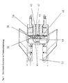
- Fig. 1 shows a tow body 1, at the rear of which there are IR flares. According to the invention, these infrared flares are ejected after ignition. The device used for this is explained below with reference to FIG. 2:
- An IR flare 12 used as the standard flare in a towed body series is used rotated by 180 ° into an ejection unit 6 until it stops.
- This IR-Flare has an open burner tube without its standard lighter.
- On the mechanical Fastening seam of the IR flare is by means of grub screw 18 Tow adapter 16 attached.
- the tow adapter 16 is over the thin tow rope 14 and the winding body 26 connected at the rear end 4 to the ejection unit 6.
- the tow rope 14 is directly in front of its connection 4 at the rear end guided a standard hitting line cutter 8, which over the pin 10 with the Tow 14 is activated (the exact overall functional sequence is shown below ) Will be explained.
- the active charge 28 of the IR flare is open to the kindling and ejection charge 32 arranged.
- the ignition and ejection charge 32 is directly from the receptacle 34 screwed into the rear of the ejection unit 6.
- the entire ejection unit 6 is screwed to the pyro base plate 2 by means of the screws 30.
- On the pyro base a total of 8 ejection units 50 (Fig. 3 and 4) are screwed, so that several Training approaches can take place.
- the active charge 28 of the IR flare is ignited at the same time, and the flare insert 12, which is sealed with the O-ring 22 to the ejection unit 6, is expelled toward the rear by the gas pressure which builds up.
- the safety wire 20 is attached for the air defense is torn off.
- the pin 10 of the reef line cutter 8 is pulled over the tow rope 14 in the first cm path.
- the inner winding 26 of the prefabricated tow rope winding 24 is completely pulled off to the intended drag length (approx. 8 m).
- the flare insert rotates through 180 ° so that the burner side points to the rear.
- the tow rope 14 is cut off at the lower end at the connection point 4 with a short time delay via the reef line cutter 8 activated at the committee.
- the burned-out flare insert 12 flies away with its tow rope 14 to the rear and makes room for the activation of a further flare. Since all further processes are mechanically and pyrotechnically coupled in the ejection unit 6 after the ejection charge 32 has been ignited, a very high level of reliability is achieved. If an ejection charge 32 fails, further ejection units can be ignited without any problems, since the flare insert 12 affected by the failure remains secured.
- the entire ejection unit 50 (FIG. 3) can be made ready for use again as often as desired by inserting a new IR flaring insert 12, tow rope winding body 24, a reef line cutter 8 and an ignition and ejection charge 32.
- the pyro unit 46 with all ejection units 50 is connected to the towed body structure 52 via a magnetically releasable coupling 48 via the structural frame 36. If, due to a malfunction (eg a reef line cutter), it is not possible to eject a towed IR flare, the entire pyro unit 46 can be ejected by releasing the clutch 48 before the towing body 52 is recovered. The electrical connection to the ignition and ejection charges 32 is automatically disconnected via the isolating plug interface 38. In order to enable a clean discharge, the entire pyro unit 46 is guided over guide tubes 40 and the guide rods 42 fastened to the structural frame 36. For preparation and storage in specially protected rooms, the entire pyro unit 46 can be removed very quickly via the central screw 44, which is easily accessible from the rear, without the need to activate electrical circuits (safety requirement).
- a malfunction eg a reef line cutter
Landscapes
- Engineering & Computer Science (AREA)
- Aviation & Aerospace Engineering (AREA)
- General Engineering & Computer Science (AREA)
- Aiming, Guidance, Guns With A Light Source, Armor, Camouflage, And Targets (AREA)
- Electric Cable Installation (AREA)
- Emergency Lowering Means (AREA)
- Photometry And Measurement Of Optical Pulse Characteristics (AREA)
Description
Da die Trefferwahrscheinlichkeit dieser Lenkwaffen (auch ohne Gefechtskopf) sehr hoch ist, geht in der Regel bei jedem Einsatz das Zieldarstellungsmittel (Drohne oder Schleppkörper) verloren.
Diese Aufgabe wird durch den Gegenstand des Hauptanspruchs gelöst. Die Unteransprüche betreffen vorteilhafte Ausgestaltungen der Erfindung.
Es zeigen:
- Fig. 1
- eine Gesamtansicht eines Schleppkörpers mit am Heck befindlichen Flares
- Fig. 2
- eine erfindungsgemässe Flare-Auswurfeinheit in Schnittdarstellung
- Fig. 3
- einen Pyro-Einsatz kombiniert mit einer Notabwurfeinrichtung
- Fig. 4
- die Flareauswurfeinheit von Fig. 2 in Heckansicht und
- Fig. 5
- einen Schleppkörper mit ausgeworfenem Flare während der Abbrennphase des Flares.
Die gesamte Auswurfeinheit 50 (Fig.3) läßt sich durch Einsetzen eines neuen IR-Flareinsatzes 12, Schleppseilwickelkörpers 24, eines Reffleinenschneiders 8 sowie einer Anzünd- und Auswurfladung 32 beliebig oft wieder einsatzbereit machen.
Zur Aufbereitung und zur Lagerung in speziell geschützten Räumen kann die gesamte Pyroeinheit 46 über die leicht von hinten zugängliche Zentralschraube 44 sehr schnell entfernt werden ohne dass elektrische Schaltkreise aktiviert werden müssen (Sicherheitsforderung).
- 1
- Schleppkörper
- 2
- Pyrogrundplatte
- 4
- Schleppseilanbindung
- 6
- Auswurfeinheit
- 8
- Reffleinenschneider
- 10
- Stift
- 12
- IR-Flareeinsatz
- 14
- Schleppseil
- 16
- Schleppadapter
- 18
- Madenschraube
- 20
- Sicherungsdraht
- 22
- O-Ring
- 24
- Schleppseilwickel
- 26
- Innenwicklung
- 28
- IR-Wirkladung
- 30
- Befestigungsschraube
- 32
- Auswurfladung und Anzündladung
- 34
- Aufnahme
- 36
- Strukturrahmen
- 38
- Trennsteckerschnittstelle
- 40
- Führungsrohr
- 42
- Führungsstange
- 44
- Zentralschraube
- 46
- Pyroeinheit
- 48
- Elektrische Magnetkupplung
- 50
- Auswurfeinheit
- 52
- Schleppkörperstruktur
Claims (4)
- Schleppkörper mit an seinem Heck befindlichen Infrarot-Flares, dadurch gekennzeichnet, dass jeder Flare (12) sich in einer Auswurfeinheit (6) befindet und mittels eines abspulbaren Schleppseils (14) während der Brenndauer vom Schleppkörper (1) gezogen wird und dass nach dem Abbrennen des Flares (12) ein Reffleinenschneider (8) das Schleppseil kappt.
- Infratrot-Flare nach Anspruch 1, gekennzeichnet durch eine Anzündladung (32), die in der Auswurfeinheit (6) einen IR-Flare (12) zündet und sich nach dem Zünden ein Gasdruck innerhalb der Auswurfeinheit aufbaut, der den Flare (12) heraustreibt, wobei ein Sicherungsdraht (20) abgerissen wird.
- Infrarot-Flare nach Ansprüchen 1 - 2, dadurch gekennzeichnet, dass das Schleppseil 14 mittels einer Madenschraube (18) am IR-Flare 12 befestigt ist, und dass beim Heraustreiben des Flares (12) aus der Auswurfeinheit (6) vom Schleppseil (14) ein Stift (10) eines Reffleinenschneiders (8) betätigt wird und nachfolgend die Innenwicklung (26) des vorkonfektionierten Schleppseilwickels (24) vollständig abgezogen wird, und dass der Flare (12) unter der Spannung des Schleppseils (14) sich um 180° dreht, sodass die Brennseite nach hinten zeigt.
- Schleppkörper nach Anspruch 1 mit Flares nach Ansprüchen 2 - 3, dadurch gekennzeichnet, dass eine Pyroeinheit (46) mit Auswurfeinheiten (50) mittels einer magnetisch auslösbaren Kupplung (48) über den Strukturrahmen (36) mit der Schleppkörperstruktur (52) verbunden ist.
Applications Claiming Priority (2)
| Application Number | Priority Date | Filing Date | Title |
|---|---|---|---|
| DE19814936A DE19814936C1 (de) | 1998-04-03 | 1998-04-03 | Schleppkörper zur Flugzieldarstellung mit IR-Flares |
| DE19814936 | 1998-04-03 |
Publications (2)
| Publication Number | Publication Date |
|---|---|
| EP0947799A1 EP0947799A1 (de) | 1999-10-06 |
| EP0947799B1 true EP0947799B1 (de) | 2002-11-13 |
Family
ID=7863464
Family Applications (1)
| Application Number | Title | Priority Date | Filing Date |
|---|---|---|---|
| EP99102181A Expired - Lifetime EP0947799B1 (de) | 1998-04-03 | 1999-02-04 | Drohne oder Schleppkörper zur Flugzieldarstellung mit IR-Flares |
Country Status (4)
| Country | Link |
|---|---|
| US (1) | US6393989B1 (de) |
| EP (1) | EP0947799B1 (de) |
| DE (2) | DE19814936C1 (de) |
| ES (1) | ES2187082T3 (de) |
Families Citing this family (8)
| Publication number | Priority date | Publication date | Assignee | Title |
|---|---|---|---|---|
| DE10021999A1 (de) * | 2000-05-05 | 2001-11-08 | Comet Gmbh Pyrotechnik Appbau | Scheinziel zur Flugzieldarstellung |
| DE10061752C1 (de) * | 2000-12-12 | 2002-05-02 | Dornier Gmbh | Abwurfeinheit für IR-Flares |
| DE10061748C1 (de) * | 2000-12-12 | 2002-06-13 | Dornier Gmbh | Schleppkörper zur Flugzieldarstellung |
| DE10061772C1 (de) * | 2000-12-12 | 2002-05-08 | Dornier Gmbh | Stabilisierungseinheit für einen Schleppkörper |
| ES2306542B1 (es) * | 2004-05-12 | 2009-11-06 | Jose Manuel Bonilla Sanchez | Blanco aereo. |
| US8403253B1 (en) | 2009-03-18 | 2013-03-26 | Israel Aerospace Industries Ltd. | Active IR signature target simulation system and a method thereof |
| US12054252B2 (en) | 2020-11-06 | 2024-08-06 | Yana SOS, Inc. | Flight-enabled signal beacon |
| CN112550752B (zh) * | 2020-12-30 | 2022-10-14 | 阿坝师范学院 | 一种高原中低空监察用多模起降无人机 |
Family Cites Families (8)
| Publication number | Priority date | Publication date | Assignee | Title |
|---|---|---|---|---|
| US3135511A (en) * | 1961-02-27 | 1964-06-02 | Hayes Corp | Towed target |
| US3458197A (en) * | 1966-07-15 | 1969-07-29 | Us Navy | Consumable infrared flare tow target |
| DE2816439C2 (de) * | 1978-04-15 | 1985-04-04 | Rhein-Flugzeugbau GmbH, 4050 Mönchengladbach | Luftschleppzielanordnung |
| DE8401068U1 (de) * | 1984-01-16 | 1984-10-18 | Stadlberger, Wolf-Rüdiger, 2081 Haseldorf | Pyrotechnisches Scheinziel |
| US5058969A (en) * | 1990-05-09 | 1991-10-22 | Hughes Aircraft Company | Optical fiber dispensing system |
| DE4116302C2 (de) * | 1991-05-14 | 1996-07-11 | Ingbuero Fuer Elektro Mechanis | Luftziel-Schleppkörper mit in dessen Innenraum angeordneten Rauchmarkiererpatronen |
| DE19543489C1 (de) * | 1995-11-22 | 1997-06-26 | Buck Chem Tech Werke | Schutzeinrichtung für sich rasch bewegende Objekte |
| US6055909A (en) * | 1998-09-28 | 2000-05-02 | Raytheon Company | Electronically configurable towed decoy for dispensing infrared emitting flares |
-
1998
- 1998-04-03 DE DE19814936A patent/DE19814936C1/de not_active Expired - Fee Related
-
1999
- 1999-02-04 EP EP99102181A patent/EP0947799B1/de not_active Expired - Lifetime
- 1999-02-04 DE DE59903370T patent/DE59903370D1/de not_active Expired - Fee Related
- 1999-02-04 ES ES99102181T patent/ES2187082T3/es not_active Expired - Lifetime
- 1999-04-02 US US09/285,468 patent/US6393989B1/en not_active Expired - Fee Related
Also Published As
| Publication number | Publication date |
|---|---|
| ES2187082T3 (es) | 2003-05-16 |
| EP0947799A1 (de) | 1999-10-06 |
| US6393989B1 (en) | 2002-05-28 |
| DE19814936C1 (de) | 1999-10-07 |
| DE59903370D1 (de) | 2002-12-19 |
Similar Documents
| Publication | Publication Date | Title |
|---|---|---|
| EP3548833B1 (de) | Startanordnung mit einem flugkörper zum abfangen von fremddrohnen | |
| EP1816427B1 (de) | Munitionsmagazin und damit ausgebildete Selbstschutz-Werfereinrichtung | |
| EP0164732B1 (de) | Einrichtung zur Erzeugung einer Scheinzielwolke, insbesondere einer Infrarot-Scheinzielwolke | |
| DE69809389T2 (de) | Vorrichtung zur unterstützung eines geschosses im rohr | |
| DE2802478C2 (de) | Vorrichtung zur Darstellung der Lichtblitz- und/oder Rauchentwicklung von Munition | |
| DE3048206A1 (de) | Uebungsgeschoss | |
| DE2842797C2 (de) | Wurfkörper | |
| DE1703557C3 (de) | ||
| EP0947799B1 (de) | Drohne oder Schleppkörper zur Flugzieldarstellung mit IR-Flares | |
| DE2458607A1 (de) | Flugziel mit radarverstaerkung | |
| EP3679314B1 (de) | Flugkörper zur drohnenbekämpfung | |
| DE2556075C2 (de) | Kartusche zum Verschießen von als Köder dienenden Zielobjekten | |
| DE7905852U1 (de) | Einheitsladung | |
| DE69721772T2 (de) | Feuerwerk zum bekämpfen von vogelgefahr | |
| DE2125149A1 (de) | Waffe | |
| DE1958355A1 (de) | Flugkoerpersystem | |
| DE1188478B (de) | Leuchtgeschoss | |
| DE3127522A1 (de) | "einrichtung zum anzeigen der wiedersicherung einer mine" | |
| DE2327827A1 (de) | Raketengetriebenes leuchtgeschoss | |
| DE69021800T2 (de) | Modulares Gerät zur Nachrüstung von Flugkörpern. | |
| DE19830134B4 (de) | Leuchtfackel für einen Hubschrauber und Verfahren zum Erzeugen einer Köderspur | |
| DE1094621B (de) | Raketeneinrichtung zum Auswerfen einer Leine, insbesondere fuer Seenotrettungszwecke | |
| DE69326258T2 (de) | System zum auflösen von nebel | |
| EP1873475B1 (de) | Manövermunition | |
| DE932348C (de) | Mit aufgehaengten Raketen ausgeruestetes Kampfgeraet, insbesondere Luftfahrzeug |
Legal Events
| Date | Code | Title | Description |
|---|---|---|---|
| PUAI | Public reference made under article 153(3) epc to a published international application that has entered the european phase |
Free format text: ORIGINAL CODE: 0009012 |
|
| AK | Designated contracting states |
Kind code of ref document: A1 Designated state(s): DE ES FR GB IT |
|
| AX | Request for extension of the european patent |
Free format text: AL;LT;LV;MK;RO;SI |
|
| 17P | Request for examination filed |
Effective date: 20000330 |
|
| AKX | Designation fees paid |
Free format text: DE ES FR GB IT |
|
| 17Q | First examination report despatched |
Effective date: 20010612 |
|
| GRAG | Despatch of communication of intention to grant |
Free format text: ORIGINAL CODE: EPIDOS AGRA |
|
| GRAG | Despatch of communication of intention to grant |
Free format text: ORIGINAL CODE: EPIDOS AGRA |
|
| GRAH | Despatch of communication of intention to grant a patent |
Free format text: ORIGINAL CODE: EPIDOS IGRA |
|
| GRAH | Despatch of communication of intention to grant a patent |
Free format text: ORIGINAL CODE: EPIDOS IGRA |
|
| GRAA | (expected) grant |
Free format text: ORIGINAL CODE: 0009210 |
|
| AK | Designated contracting states |
Kind code of ref document: B1 Designated state(s): DE ES FR GB IT |
|
| REG | Reference to a national code |
Ref country code: GB Ref legal event code: FG4D Free format text: NOT ENGLISH |
|
| REF | Corresponds to: |
Ref document number: 59903370 Country of ref document: DE Date of ref document: 20021219 |
|
| GBT | Gb: translation of ep patent filed (gb section 77(6)(a)/1977) |
Effective date: 20030315 |
|
| REG | Reference to a national code |
Ref country code: ES Ref legal event code: FG2A Ref document number: 2187082 Country of ref document: ES Kind code of ref document: T3 |
|
| ET | Fr: translation filed | ||
| PLBE | No opposition filed within time limit |
Free format text: ORIGINAL CODE: 0009261 |
|
| STAA | Information on the status of an ep patent application or granted ep patent |
Free format text: STATUS: NO OPPOSITION FILED WITHIN TIME LIMIT |
|
| 26N | No opposition filed |
Effective date: 20030814 |
|
| PGFP | Annual fee paid to national office [announced via postgrant information from national office to epo] |
Ref country code: GB Payment date: 20050131 Year of fee payment: 7 |
|
| PGFP | Annual fee paid to national office [announced via postgrant information from national office to epo] |
Ref country code: DE Payment date: 20050208 Year of fee payment: 7 |
|
| REG | Reference to a national code |
Ref country code: GB Ref legal event code: 732E |
|
| PGFP | Annual fee paid to national office [announced via postgrant information from national office to epo] |
Ref country code: FR Payment date: 20050210 Year of fee payment: 7 |
|
| PGFP | Annual fee paid to national office [announced via postgrant information from national office to epo] |
Ref country code: ES Payment date: 20050218 Year of fee payment: 7 |
|
| REG | Reference to a national code |
Ref country code: FR Ref legal event code: TP |
|
| PG25 | Lapsed in a contracting state [announced via postgrant information from national office to epo] |
Ref country code: GB Free format text: LAPSE BECAUSE OF NON-PAYMENT OF DUE FEES Effective date: 20060204 |
|
| PG25 | Lapsed in a contracting state [announced via postgrant information from national office to epo] |
Ref country code: ES Free format text: LAPSE BECAUSE OF NON-PAYMENT OF DUE FEES Effective date: 20060206 |
|
| PGFP | Annual fee paid to national office [announced via postgrant information from national office to epo] |
Ref country code: IT Payment date: 20060228 Year of fee payment: 8 |
|
| PG25 | Lapsed in a contracting state [announced via postgrant information from national office to epo] |
Ref country code: DE Free format text: LAPSE BECAUSE OF NON-PAYMENT OF DUE FEES Effective date: 20060901 |
|
| GBPC | Gb: european patent ceased through non-payment of renewal fee |
Effective date: 20060204 |
|
| REG | Reference to a national code |
Ref country code: FR Ref legal event code: ST Effective date: 20061031 |
|
| REG | Reference to a national code |
Ref country code: ES Ref legal event code: FD2A Effective date: 20060206 |
|
| PG25 | Lapsed in a contracting state [announced via postgrant information from national office to epo] |
Ref country code: FR Free format text: LAPSE BECAUSE OF NON-PAYMENT OF DUE FEES Effective date: 20060228 |
|
| PG25 | Lapsed in a contracting state [announced via postgrant information from national office to epo] |
Ref country code: IT Free format text: LAPSE BECAUSE OF NON-PAYMENT OF DUE FEES Effective date: 20070204 |