EP0943571A2 - Fadenliefergerät mit verbessertem Fadenlauf - Google Patents
Fadenliefergerät mit verbessertem Fadenlauf Download PDFInfo
- Publication number
- EP0943571A2 EP0943571A2 EP99103639A EP99103639A EP0943571A2 EP 0943571 A2 EP0943571 A2 EP 0943571A2 EP 99103639 A EP99103639 A EP 99103639A EP 99103639 A EP99103639 A EP 99103639A EP 0943571 A2 EP0943571 A2 EP 0943571A2
- Authority
- EP
- European Patent Office
- Prior art keywords
- thread
- thread delivery
- wheel
- delivery device
- delivery wheel
- Prior art date
- Legal status (The legal status is an assumption and is not a legal conclusion. Google has not performed a legal analysis and makes no representation as to the accuracy of the status listed.)
- Granted
Links
- 230000001154 acute effect Effects 0.000 claims abstract description 10
- 238000001514 detection method Methods 0.000 claims description 2
- 230000007704 transition Effects 0.000 claims 1
- 238000011144 upstream manufacturing Methods 0.000 claims 1
- 238000004804 winding Methods 0.000 abstract description 8
- 238000009940 knitting Methods 0.000 description 10
- 238000000034 method Methods 0.000 description 3
- 238000000926 separation method Methods 0.000 description 3
- 229920002334 Spandex Polymers 0.000 description 2
- 230000001419 dependent effect Effects 0.000 description 2
- 238000005516 engineering process Methods 0.000 description 2
- 230000001105 regulatory effect Effects 0.000 description 2
- 239000004753 textile Substances 0.000 description 2
- 230000001133 acceleration Effects 0.000 description 1
- 230000009286 beneficial effect Effects 0.000 description 1
- 238000010276 construction Methods 0.000 description 1
- 230000005284 excitation Effects 0.000 description 1
- 239000000835 fiber Substances 0.000 description 1
- 238000005259 measurement Methods 0.000 description 1
- 230000001151 other effect Effects 0.000 description 1
Images
Classifications
-
- B—PERFORMING OPERATIONS; TRANSPORTING
- B65—CONVEYING; PACKING; STORING; HANDLING THIN OR FILAMENTARY MATERIAL
- B65H—HANDLING THIN OR FILAMENTARY MATERIAL, e.g. SHEETS, WEBS, CABLES
- B65H51/00—Forwarding filamentary material
- B65H51/20—Devices for temporarily storing filamentary material during forwarding, e.g. for buffer storage
- B65H51/22—Reels or cages, e.g. cylindrical, with storing and forwarding surfaces provided by rollers or bars
-
- D—TEXTILES; PAPER
- D04—BRAIDING; LACE-MAKING; KNITTING; TRIMMINGS; NON-WOVEN FABRICS
- D04B—KNITTING
- D04B15/00—Details of, or auxiliary devices incorporated in, weft knitting machines, restricted to machines of this kind
- D04B15/38—Devices for supplying, feeding, or guiding threads to needles
- D04B15/48—Thread-feeding devices
- D04B15/52—Thread-feeding devices for straight-bar knitting machines
Definitions
- the invention relates to a yarn delivery device with the Features of the preamble of claim 1.
- Knitting points or other thread consumption points are in use the required thread consumption point Allocate thread quantity and regardless of the actual Thread take-off at the thread consumption point, respectively.
- Such a supplier is, for example, from DE 3601586 C1 known. This supplier is special intended for circular knitting machines, the knitting points with have constant thread consumption.
- the supplier has a shaft rotatably mounted in a base support on, at one end a thread delivery drum rotatably is held.
- the other end of the wave is with one Pulley provided which engages with a toothed belt stands. This toothed belt is driven centrally and runs over the pulleys of many such thread delivery devices, which thus drive at the same constant speed are.
- the thread delivery drum has an outer circumference, that of a plurality extending axially Rods is set.
- the rods are in at the end End discs held on their facing the bars Side are essentially conical.
- the Thread delivery drum is repeated several times by the thread to be delivered wrapped around so that the drum pulled the thread from one Pulls off the bobbin and delivers it to the knitting point.
- the thread is passed through eyelets, which thus define a thread path.
- the on the thread delivery drum following eyelet is axially against the Thread delivery drum offset so far that the thread is over brushes the edge of the thread delivery drum.
- Thread delivery devices of this type are for use cases well suited with essentially constant thread consumption. However, there are also applications for which the thread consumption temporarily very strong fluctuations may be subject. This is for example with flat knitting machines the case where a thread guide, the individual Needles feed the thread one after the other, one back and forth movement across the entire width of the web executes. The thread consumption is at the side Arrangement of the thread delivery device, i.e. when feeding the Thread across the web in the outward and return stroke different. In addition, the thread consumption comes in the dead center positions of the thread guide to a complete standstill. In these cases, thread delivery devices cannot be used be used, the thread in time constant Deliver quantity. Rather, it is necessary that the supplied thread an essentially constant tension to maintain a constant mesh size.
- a thread delivery device is known from DE 19537215 A1, which has a motor-driven thread delivery wheel. This is wrapped around the thread a few times. After that the thread runs to the thread tension sensor Thread consumption point. The thread tension sensor regulates the speed of the motor of the thread delivery wheel via a Control loop so that the thread tension to the setpoint is settled.
- the thread delivery wheel is by six different from one central hub, wing or wire bracket extending away educated. These each have two parallel spacings arranged to each other, extending in the radial direction Leg on, between which an axially oriented Support section is held.
- the support section goes with a U-shaped curve, projecting radially outwards Sections in the radial spokes above.
- the direction of the thread from the thread delivery wheel is, for example, also at DE 4206607 at right angles to the The axis of rotation of the thread feed wheel is fixed.
- Such yarn delivery devices are more elastic for delivery Threads provided.
- Such threads are, for example, elastane threads or other plastic fibers. Because of Their elasticity is used to monitor the thread tension critical. It can also be problematic that the often very thin (hair-fine) threads tend to Lay turns on top of each other or stick together Form turns.
- a reproducible and even time uniform separation of those supplied by the thread delivery wheel Thread quantities from lying on the thread delivery wheel Coils is particularly at changing speeds difficult to reach. However, it must be prevented that the thread at high or otherwise critical speeds not released by the thread delivery wheel, but is adherently entrained because this leads to a return and thus would lead to a tearing of the thread.
- Thread delivery device to create the threads with changing Deliver yarn speeds with good reliability can.
- the thread delivery device has a motor-driven one Thread delivery wheel on that around a fixed Axis of rotation is rotatably mounted.
- the thread path is set so that the thread is not accurate runs tangentially to the thread delivery wheel, but in one acute angle to the tangent. In other words, the thread runs at an acute angle to a plane from, the normal direction with the axis of rotation of the thread delivery wheel matches.
- the running thread runs with it of the few turns, on the Thread delivery reel lying away. He is the result of (usually low) tension of the thread on the thread delivery wheel following thread travel path from the thread delivery wheel Cut.
- Thread delivery wheel thus enables a clean thread run, surprisingly almost completely independent of speed, i.e. both at low speeds and at high speeds and abrupt acceleration and / or Braking phases.
- the inclination of the thread delivery wheel causes spacing of the individual turns of the thread winding on the thread delivery wheel from each other. Neither the turns stick to each other, they are still lying on top of each other. While at high speeds the resulting centrifugal forces acting on the thread as well radial air currents releasing the thread from the thread delivery wheel support, so here the separation can be done more easily, the diagonal pull provides support this process even at very low speeds or close to the stop of the thread delivery wheel.
- the separation of the thread running from the thread delivery wheel takes place very quickly at high speeds, because very little time is available stands.
- the diagonal draw also favors the thread flow here.
- the tension of the thread creates an axial force component, which go beyond the expiry point more or penetrates less into the wrap and causes the thread begins to slide axially in front of the outlet point can.
- the drain point can be from the adjacent turn be spaced. It can be achieved that independent of speed the angular position of the point at which the running thread separates from the thread delivery wheel, constant remains.
- a thread tension sensor without thread guide means arranged in between, Thread eyelets or the like, this is of considerable Significance for the constancy of the thread tension.
- first Section of the thread travel path in front of the thread delivery wheel looking radially to the axis of rotation of the thread delivery wheel parallel to the thread path after the thread feed wheel arranged. This is the axis of rotation of the thread delivery wheel diagonally to the otherwise straight thread path.
- first and second sections of the thread path are in the direction of the axis of rotation of the thread delivery wheel offset from each other by an amount that is preferred is greater than the product of the thread thickness and the Number of turns. This will cause the Thread supported on the guide wheel in the axial direction. This is done by the winding on the thread delivery wheel Thread created, the existing coils aside pushes.
- the guide means for the thread that is on the thread delivery wheel follows the thread only in a transverse direction leads, in relation to the thread delivery wheel, for example Circumferential direction is.
- This means that the thread is in a direction parallel to the axis of rotation here still unguided can be.
- the actual process point arises due to the inclination of the thread delivery wheel against the incoming thread automatically according to the so determined Slope that is greater than a slope, which defines a winding with adjacent turns.
- this is a free thread guide, i.e. is no guidance available.
- the thread guiding device following the thread delivery wheel can also be designed as a thread tension sensor be.
- the thread runs at an obtuse angle of preferably more than 130 ° over the sensor (pen).
- the Little deflection on the pin keeps the friction low. Due to the constancy of the run-off point from the thread delivery wheel this angle can be kept largely constant become what enables reproducible measurement results and ensures.
- Thread guide eyes at the entrance and exit of the thread delivery device ultimately make sure that outside influences of the thread delivery device, such as the positioning of thread spools or other thread guide means, no influence on the conditions have the thread delivery wheel.
- the thread delivery wheel is preferably lightweight built with few radial arms, making it quick can be accelerated and stopped, which is why regulated or controlled motor is used.
- the radial arms are, for example, formed by wire brackets, which a polygonal thread rest on the outer circumference of the thread delivery wheel establish.
- the corresponding radial arm sections are essentially axial or in a small acute angle to the axis of rotation so that the Edition is somewhat conical.
- the individual radial arms can be in on a hub be arranged at equal angular distances. However, can the angular distances also vary slightly to the excitation of natural vibrations of the thread when passing through different ones Avoid speeds.
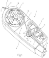
- a thread delivery device 1 is illustrated in FIG. 1, such as for the supply of elastane threads Flat knitting machines or also for the delivery of other Threads to thread consumption points of other machines Can find application.
- the thread delivery device 1 is used a thread 2 from a thread source, for example a thread spool, deduct and along a thread path 3 to the thread consumption point not further illustrated promote. This should be as appropriate as possible Quantity or with constant thread tension.
- the thread delivery device 1 has a housing 4 whose essentially flat front side 5 is a thread delivery wheel 6 is arranged, which serves the thread 2nd to promote needs.
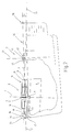
- the yarn feed wheel 6 is like Figure 2 illustrates rotatably mounted about an axis of rotation 7. For this purpose, it is preferably one on an output shaft 8 electric motor designed as a disc rotor motor 9 attached in the interior of the housing 4th is stationary.
- the thread feed wheel 6 is in Lightweight construction. Starting from its hub 9 wings or arms 11 extend radially outwards, which are formed by wire brackets. These are among themselves equally trained.
- Each arm 11 is spaced two apart parallel to each other radially away from the hub 9 extending radial spoke sections 13, 14 on the the outer periphery of the yarn feed wheel 6 by a Support web 15 are interconnected.
- the support webs 15 are essentially just formed wire sections that point in one Angles to the axis of rotation 7 are aligned. You go on both ends with a radial projection 16, 17 in the radial spoke sections 13, 14 over.
- the disc motor 9 and the thread delivery wheel 6 belong to a control loop for regulating the thread feed depending on the tension of the thread 2. This is detected by a sensor 21, which is on the thread delivery wheel 6 following on the front 5 of the housing 4 of the thread delivery device 1 is arranged.
- the thread tension sensor 21 has a support pin 22 which with a force sensor is connected. This detects thread tension dependent slightest movements of the pen 22 in the transverse direction. This is shown in Figure 1 by a arrow 23 indicated. Between the thread feed wheel 6 and the support pin 22 of the thread tension sensor 21 preferably no further thread guiding or guiding means intended.
- Thread delivery wheel 6 and the support pin 22 of the thread tension sensor 21 one arranged in front of the yarn feed wheel 6 Thread inlet eyelet 25 and one on the thread tension sensor 21 following thread outlet eyelet 26. These are arranged so that they have a first section 31 of the thread path 3 in front of the thread delivery wheel and a second section 32 of the Thread path 3 offset parallel to the thread feed wheel 6 to each other, as shown in Figure 2.
- This spatial position of the first and the second section 31, 32 of the thread path 3 results as a result the position of the thread inlet eyelet 25 and the thread outlet eyelet 26 in connection with an inclined position of the thread feed wheel 6 and, if necessary, a corresponding orientation of the support pin or its longitudinal central axis 33.
- the Thread 2 touches after the thread inlet eyelet 25 and has passed through the first thread path section 31 which Thread delivery wheel 6 for the first time at a contact point 35. Von from here it turns in at least one turn around the thread delivery wheel led around to a drain point 36, that related to the axis of rotation 7 of the yarn feed wheel 6 is axially offset against the contact point 35.
- the positioning of the thread inlet eyelet 25 and the thread outlet eyelet 26 with respect to the thread delivery wheel 6 generated axial offset between these two points 35, 36 is larger than that due to the thickness of the thread 2 predefined pitch of the turns on the thread delivery wheel 6, so that the running thread 2 on the thread delivery wheel 6 lying turns are not touched.
- this is done by arranging the thread inlet eyelet 25 below and arrangement of the thread outlet eyelet 26 reached above this median plane 41.
- the thread delivery device 1 also has a calibration device 45 for the thread tension sensor 21.
- the calibration device 45 contains two thread support pins 46, 47, the normal operation of the thread delivery device 1 are lifted from the thread 2, i.e. with this are not engaged. At certain intervals you can the thread support pins 46, 47 by actuating one Traction magnet 48 adjusted in the direction of arrow 23 that they take the thread 2 from the pin 22 of the thread tension sensor 21 take off. This serves to find the zero point. If required and / or as an alternative, the thread tension sensor can also be used 21 can be moved for calibration.
- the thread delivery device described so far works as follows:
- the thread tension sensor 21 detects the existing tension of the thread 2 corresponding to the lateral Deflection of the pin 22, which is, however, slight and is in the range of one millimeter.
- the thread consumption on a downstream of the thread delivery device 1 Thread consumption point, for example the knitting point of one Knitting machine is reflected in the thread tension, which is constantly corrected by a control loop.
- the motor 9 is controlled so that the thread delivery wheel 6 provides the amount of thread required to to keep the thread tension constant. The increases Voltage, the motor 9 is accelerated until the Thread tension has returned to its setpoint. If the thread tension drops, the thread feed wheel is slowed down (if necessary to a standstill) until the desired Thread tension is set again.
- the incoming thread 2 runs in the vicinity of its radial projections 17 on the outer circumference of the thread feed wheel 6 on an inclined section of the respective radial projection 17, wherein all inclined sections define a conical surface.
- the thread 2 wraps around the thread delivery wheel or a few times (three to five times) with an incline, which roughly corresponds to its thickness. Thread 2 runs then near or above the middle plane 41 without touching the radial projections 16. So be the edges defined by the radial projections 16, 17 of the thread feed wheel, although the thread 2 with respect to the thread feed wheel 6 slants in and out does not touch.
- a thread delivery device 1 the needs-based Positive delivery of a thread 2 with an electric motor 9 connected thread delivery wheel 6 has a thread path 3, which is guided by thread guide means 25, 26 at an angle to the axis of rotation 7 of the yarn feed wheel 6 is set, which is greater than the sum of 90 ° and an additional acute angle.
- This additional acute angle ⁇ is greater than the pitch angle a thread winder on the thread delivery wheel 6, in the adjacent Windings lie against each other. This gives there is a smooth flow of the lying on the thread delivery wheel 6 Thread 2.
Landscapes
- Engineering & Computer Science (AREA)
- Textile Engineering (AREA)
- Knitting Machines (AREA)
- Forwarding And Storing Of Filamentary Material (AREA)
- Guides For Winding Or Rewinding, Or Guides For Filamentary Materials (AREA)
- Unwinding Of Filamentary Materials (AREA)
- Spinning Or Twisting Of Yarns (AREA)
- Tension Adjustment In Filamentary Materials (AREA)
- Spinning Methods And Devices For Manufacturing Artificial Fibers (AREA)
Abstract
Description
Claims (20)
- Fadenliefergerät (1), zum Zuliefern von Fäden, insbesondere elastischen Fäden, zu Fadenverbrauchsstellen insbesondere mit zeitlich schwankendem Fadenverbrauch,mit einem Fadenlieferrad (6), das um eine Drehachse (7) drehbar gelagert und in einem Fadenlaufweg (3) angeordnet ist, so dass es von einem Faden (2) umschlingbar ist,mit einem Motor (9), der mit dem Fadenlieferrad (6) drehfest verbunden ist, um dieses unter Förderung des Fadens (2) anzutreiben,
dadurch gekennzeichnet,dass der Fadenlaufweg (3) im Anschluss an das Fadenlieferrad (6) in einem spitzen, von Null verschiedenen Winkel (α) zu einer Ebene (41) festgelegt ist, auf der die Drehachse (7) senkrecht steht. - Fadenliefergerät nach Anspruch 1, dadurch gekennzeichnet, dass der Motor (9) das Fadenlieferrad (6) trägt und dass der Motor eine Drehachse aufweist, die mit der Drehachse (7) des Fadenlieferrads (6) übereinstimmt.
- Fadenliefergerät nach Anspruch 1, dadurch gekennzeichnet, dass der Fadenlaufweg (3) des Fadenliefergeräts (1), den der Faden (2) unter anderem durchläuft, wenn er von einer Fadenquelle zu einer Fadenverbrauchsstelle geliefert wird, von Fadenführungsmitteln (25, 6, 22, 26) festgelegt ist,
wobei zu den Fadenführungsmitteln (25, 6, 22, 26) wenigstens das Fadenlieferrad (6) und eine auf das Fadenlieferrad (6) folgend angeordnete Fadenleiteinrichtung (22) gehören, die den Faden (2) von dem Fadenlieferrad (6) ohne Randberührung ablaufend führt. - Fadenliefergerät nach Anspruch 3, dadurch gekennzeichnet, dass der von den Fadenführungsmitteln (25, 6, 22, 26) festgelegt Fadenlaufweg (3) einen zu dem Fadenlieferrad (6) führenden ersten Abschnitt (31) und einen von dem Fadenlieferrad (6) weg führenden zweiten Abschnitt (32) aufweist, und dass der erste Abschnitt (31) in einer Ebene angeordnet ist, die parallel zu einer den zweiten Abschnitt (32) enthaltenden Ebene ist.
- Fadenliefergerät nach Anspruch 4, dadurch gekennzeichnet, dass der Abstand zwischen den Ebenen größer ist als das Produkt aus der maximalen Fadendicke und der Maximalzahl der Windungen, mit denen der Faden (2) das Fadenlieferrad (6) umschlingt.
- Fadenliefergerät nach Anspruch 3, dadurch gekennzeichnet, dass das Fadenführungsmittel (25, 6, 22, 26) eine Leiteinrichtung (22) enthält, die den Faden (2) ausschließlich in einer ersten Querrichtung (23) führt, wobei die Fadenleiteinrichtung (22) vorzugsweise als Stift (22) ausgebildet ist, über den der Faden (2) in Stiftlängsrichtung (23) frei beweglich läuft, und wobei der Faden (2) an der Leiteinrichtung (22) in einem stumpfen Winkel anliegt, der größer als 130° ist.
- Fadenliefergerät nach Anspruch 6, dadurch gekennzeichnet, dass die Leiteinrichtung (22) mit einer Sensoreinrichtung (21) zur Erfassung der Fadenspannung verbunden ist.
- Fadenliefergerät nach Anspruch 7, dadurch gekennzeichnet, dass die Leiteinrichtung (22) im wesentlichen unbeweglich gelagert ist.
- Fadenliefergerät nach Anspruch 6, dadurch gekennzeichnet, dass der Stift (22) eine Längsachse (33) aufweist, die mit der Drehachse (7) einen spitzen Winkel einschließt, der vorzugsweise kleiner als 10° ist.
- Fadenliefergerät nach Anspruch 6, dadurch gekennzeichnet, dass zu dem Fadenführungsmittel (25, 6, 22, 26) außer der Leiteinrichtung (22) eine Führungseinrichtung (26) gehört, die vorzugsweise auf die Leiteinrichtung (22) folgend angeordnet ist.
- Fadenliefergerät nach Anspruch 10, dadurch gekennzeichnet, dass die Führungseinrichtung (26) den Faden (2) wenigstens in einer zweiten Querrichtung führt und vorzugsweise als Öse ausgebildet ist.
- Fadenliefergerät nach Anspruch 3 oder 10, dadurch gekennzeichnet, dass die Führungseinrichtung (26) und der sich zwischen dem Fadenlieferrad (6) und der Führungseinrichtung ergebende Abschnitt (32) des Fadenlaufwegs in einer Ebene angeordnet sind, die das Fadenlieferrad (6) an seinem gesamten Umfang schneidet.
- Fadenliefergerät nach Anspruch 1, dadurch gekennzeichnet, dass der Winkel (α) größer, vorzugsweise größer als doppelt so groß ist als ein Steigungswinkel, der sich in einem Fadenwickel mit abstandsfrei auf dem Fadenlieferrad (6) angeordneten Windungen ergibt.
- Fadenliefergerät nach Anspruch 1, dadurch gekennzeichnet, dass der Motor von einer Ansteuereinrichtung gesteuert ist, die diesen anhand der Fadenspannung steuert.
- Fadenliefergerät nach Anspruch 1, dadurch gekennzeichnet, dass der Motor (9) ein trägheitsarmer Motor, vorzugsweise ein Scheibenläufermotor ist.
- Fadenliefergerät nach Anspruch 1, dadurch gekennzeichnet, dass das Fadenlieferrad (6) mehrere untereinander im wesentlichen gleich ausgebildete Radialarme (11) aufweist, die in vorzugsweise gleichen Winkelabständen zueinander angeordnet sind.
- Fadenliefergerät nach Anspruch 16, dadurch gekennzeichnet, dass die Radialarme (11) in wechselnden Winkelabständen angeordnet sind.
- Fadenliefergerät nach Anspruch 16, dadurch gekennzeichnet, dass die Radialarme (11) durch Drahtbügel gebildet sind, die jeweils zwei Radialspeichenabschnitte (13, 14) aufweisen, die untereinander durch einen im Wesentlichen axialen Auflageabschnitt (15) verbunden sind.
- Fadenliefergerät nach Anspruch 18, dadurch gekennzeichnet, dass im Übergang zwischen dem Axialabschnitt (15) und dem Radialspeichenabschnitt (13, 14) ein Radialvorsprung (16, 17) ausgebildet ist.
- Fadenliefergerät nach Anspruch 1, dadurch gekennzeichnet, dass in dem Fadenlaufweg (3) dem Fadenlieferrad (6) vorgelagert eine Führungseinrichtung (25) vorgesehen ist, die mit dem sich zwischen dem Fadenlieferrad (6) und der Führungseinrichtung (25) ergebende Abschnitt (31) des Fadenlaufwegs (3) in einer Ebene angeordnet ist, die das Fadenlieferrad (6) an seinem gesamten Umfang schneidet.
Applications Claiming Priority (2)
| Application Number | Priority Date | Filing Date | Title |
|---|---|---|---|
| DE19811240A DE19811240C2 (de) | 1998-03-14 | 1998-03-14 | Fadenliefergerät mit verbessertem Fadenlauf |
| DE19811240 | 1998-03-14 |
Publications (3)
| Publication Number | Publication Date |
|---|---|
| EP0943571A2 true EP0943571A2 (de) | 1999-09-22 |
| EP0943571A3 EP0943571A3 (de) | 2000-01-12 |
| EP0943571B1 EP0943571B1 (de) | 2004-06-09 |
Family
ID=7860990
Family Applications (1)
| Application Number | Title | Priority Date | Filing Date |
|---|---|---|---|
| EP99103639A Expired - Lifetime EP0943571B1 (de) | 1998-03-14 | 1999-02-25 | Fadenliefergerät mit verbessertem Fadenlauf |
Country Status (16)
| Country | Link |
|---|---|
| US (1) | US6131842A (de) |
| EP (1) | EP0943571B1 (de) |
| JP (1) | JP3133298B2 (de) |
| KR (1) | KR19990077813A (de) |
| CN (1) | CN1238297A (de) |
| BR (1) | BR9901004A (de) |
| CA (1) | CA2265382C (de) |
| CO (1) | CO4810243A1 (de) |
| DE (2) | DE19811240C2 (de) |
| ES (1) | ES2218889T3 (de) |
| ID (1) | ID22179A (de) |
| IL (1) | IL128885A (de) |
| RU (1) | RU2162816C2 (de) |
| TR (1) | TR199900565A2 (de) |
| TW (1) | TW473452B (de) |
| UY (1) | UY25424A1 (de) |
Families Citing this family (12)
| Publication number | Priority date | Publication date | Assignee | Title |
|---|---|---|---|---|
| DE10333202A1 (de) * | 2003-07-22 | 2005-03-03 | Hottinger Baldwin Messtechnik Gmbh | Gehäuse für einen Fadenspannungsaufnehmer |
| DE602009000914D1 (de) | 2009-02-16 | 2011-04-28 | Lgl Electronics Spa | Fadenliefervorrichtung mit einer leichten Fadenaufwickeltrommel |
| KR101227238B1 (ko) * | 2011-08-19 | 2013-01-28 | 파이룽 머시너리 밀 코., 엘티디. | 횡편기를 위한 직접 구동 보조 실 가이드 장치 |
| DE102012111784B3 (de) * | 2012-12-04 | 2014-03-27 | Memminger-Iro Gmbh | Fadenliefergerät |
| LU92683B1 (fr) * | 2013-07-24 | 2015-07-24 | Kordsa Global Endustriyel Iplik Ve Kord Bezi Sanay | Unité de contrôle de diamètre de ballon un appareil de câblage |
| ITTO20130875A1 (it) * | 2013-10-29 | 2015-04-30 | Lgl Electronics Spa | Alimentatore di filato positivo con controllo della tensione di alimentazione. |
| EP3230510B1 (de) | 2014-12-09 | 2021-10-20 | Memminger-IRO GmbH | Verfahren und vorrichtung zur überwachung einer strickmaschine |
| DE102015014385A1 (de) * | 2015-11-09 | 2017-05-11 | Saurer Germany Gmbh & Co. Kg | Verfahren zum Korrigieren eines Fadenlaufs bei einer Arbeitsstelle einer Kreuzspulen herstellenden Textilmaschine |
| ITUB20160067A1 (it) | 2016-01-26 | 2017-07-26 | Lgl Electronics Spa | Dispositivo di recupero di filato per apparati tessili. |
| ITUA20164460A1 (it) * | 2016-06-17 | 2017-12-17 | Lgl Electronics Spa | Alimentatore di filato con rocchetto avvolgi-filo motorizzato |
| JP7111491B2 (ja) * | 2018-03-30 | 2022-08-02 | 株式会社島精機製作所 | 横編機 |
| DE102018115631A1 (de) * | 2018-06-28 | 2020-01-02 | Memminger-Iro Gmbh | Fadenliefergerät und System mit einem Fadenliefergerät |
Family Cites Families (17)
| Publication number | Priority date | Publication date | Assignee | Title |
|---|---|---|---|---|
| US3669584A (en) * | 1968-10-24 | 1972-06-13 | Teijin Ltd | Melt-spinning apparatus |
| DE2639207C3 (de) * | 1976-08-31 | 1981-03-12 | Memminger Gmbh, 7290 Freudenstadt | Fadenliefervorrichtung |
| FR759330A (fr) * | 1980-03-03 | 1934-02-01 | Chaise | |
| DE3416195C2 (de) * | 1984-05-02 | 1987-01-08 | Gustav 7290 Freudenstadt Memminger | Fadenliefervorrichtung für fadenverarbeitende Textilmaschinen, bspw. Rundstrick- oder -wirkmaschinen |
| DE3417936C2 (de) * | 1984-05-15 | 1986-06-26 | Memminger Gmbh, 7290 Freudenstadt | Fadenliefervorrichtung für Textilmaschinen |
| DE3429207C2 (de) * | 1984-08-08 | 1986-06-19 | Gustav 7290 Freudenstadt Memminger | Fadenliefervorrichtung für fadenverbrauchende Textilmaschinen |
| DE3437252C1 (de) * | 1984-10-11 | 1986-01-16 | Gustav 7290 Freudenstadt Memminger | Fadenspeicher- und -liefervorrichtung,insbesndere fuer Textilmaschinen |
| DE3437251A1 (de) * | 1984-10-11 | 1986-04-24 | Gustav 7290 Freudenstadt Memminger | Fadenbremse, insbesondere fuer textilmaschinen |
| DE3501944A1 (de) * | 1985-01-22 | 1986-07-24 | SIPRA Patententwicklungs- und Beteiligungsgesellschaft mbH, 7470 Albstadt | Fadenliefervorrichtung fuer textilmaschinen |
| DE3601586C1 (de) * | 1986-01-21 | 1987-05-27 | Memminger Gmbh | Fadenspeicher- und -liefervorrichtung,insbesondere fuer Textilmaschinen |
| DE3627731C1 (de) * | 1986-08-16 | 1988-03-31 | Gustav Memminger | Fadenliefervorrichtung mit elektronischer Fadenspannungsregelung |
| DE3711558C1 (de) * | 1987-04-06 | 1988-06-23 | Sipra Patent Beteiligung | Fadenliefervorrichtung fuer Strickmaschinen |
| DE3820618A1 (de) * | 1988-06-17 | 1989-12-28 | Gustav Memminger | Fadenliefervorrichtung fuer kraeusel- oder andere effektgarne |
| DE4206607A1 (de) * | 1991-09-26 | 1993-04-01 | Erich Roser | Fadenliefergeraet fuer fadenverbrauchende textilmaschinen |
| JP2731316B2 (ja) | 1992-03-27 | 1998-03-25 | 財団法人鉄道総合技術研究所 | 保護継電器 |
| DE19537215C2 (de) * | 1995-10-06 | 1999-09-02 | Memminger Iro Gmbh | Fadenliefergerät für elastische Garne |
| US5860298A (en) * | 1997-05-23 | 1999-01-19 | Jen Hui Chen | Thread feeder with thread-twisting preventive device for knitting machines |
-
1998
- 1998-03-14 DE DE19811240A patent/DE19811240C2/de not_active Expired - Fee Related
-
1999
- 1999-02-25 DE DE59909667T patent/DE59909667D1/de not_active Expired - Lifetime
- 1999-02-25 EP EP99103639A patent/EP0943571B1/de not_active Expired - Lifetime
- 1999-02-25 ES ES99103639T patent/ES2218889T3/es not_active Expired - Lifetime
- 1999-03-08 JP JP11059865A patent/JP3133298B2/ja not_active Expired - Fee Related
- 1999-03-08 IL IL12888599A patent/IL128885A/xx not_active IP Right Cessation
- 1999-03-10 ID IDP990199A patent/ID22179A/id unknown
- 1999-03-11 UY UY25424A patent/UY25424A1/es not_active Application Discontinuation
- 1999-03-12 CA CA002265382A patent/CA2265382C/en not_active Expired - Fee Related
- 1999-03-12 RU RU99105266/12A patent/RU2162816C2/ru not_active IP Right Cessation
- 1999-03-12 BR BR9901004-6A patent/BR9901004A/pt active Search and Examination
- 1999-03-12 CO CO99015393A patent/CO4810243A1/es unknown
- 1999-03-12 TW TW088103791A patent/TW473452B/zh not_active IP Right Cessation
- 1999-03-12 CN CN99103983A patent/CN1238297A/zh active Pending
- 1999-03-12 TR TR1999/00565A patent/TR199900565A2/xx unknown
- 1999-03-12 KR KR1019990008227A patent/KR19990077813A/ko not_active Ceased
- 1999-03-15 US US09/268,406 patent/US6131842A/en not_active Expired - Fee Related
Also Published As
| Publication number | Publication date |
|---|---|
| US6131842A (en) | 2000-10-17 |
| UY25424A1 (es) | 1999-07-19 |
| CN1238297A (zh) | 1999-12-15 |
| DE19811240A1 (de) | 1999-09-30 |
| JPH11292393A (ja) | 1999-10-26 |
| CO4810243A1 (es) | 1999-06-30 |
| JP3133298B2 (ja) | 2001-02-05 |
| KR19990077813A (ko) | 1999-10-25 |
| TW473452B (en) | 2002-01-21 |
| ES2218889T3 (es) | 2004-11-16 |
| CA2265382A1 (en) | 1999-09-14 |
| IL128885A (en) | 2003-05-29 |
| RU2162816C2 (ru) | 2001-02-10 |
| ID22179A (id) | 1999-09-16 |
| DE59909667D1 (de) | 2004-07-15 |
| EP0943571A3 (de) | 2000-01-12 |
| TR199900565A3 (tr) | 1999-10-21 |
| CA2265382C (en) | 2004-11-09 |
| TR199900565A2 (xx) | 1999-10-21 |
| EP0943571B1 (de) | 2004-06-09 |
| BR9901004A (pt) | 2000-03-08 |
| IL128885A0 (en) | 2000-01-31 |
| DE19811240C2 (de) | 2000-05-31 |
Similar Documents
| Publication | Publication Date | Title |
|---|---|---|
| EP0943571B1 (de) | Fadenliefergerät mit verbessertem Fadenlauf | |
| DE3326099C2 (de) | Fadenliefervorrichtung für Textilmaschinen | |
| CH646210A5 (de) | Verfahren und vorrichtung zur erzeugung einer verbindung von faserverbaenden. | |
| EP2758578B1 (de) | Fadenliefergerät zur zufuhr eines fadens zu einer textilmaschine | |
| DE2164095C3 (de) | Fadenliefer- und -speichervorrichtung für Textilmaschinen | |
| DE3923305C2 (de) | Zylindrische Spulhülse | |
| DE1303605B (de) | ||
| DE4336994C1 (de) | Fadenliefervorrichtung mit stufenlos einstellbarer Fadenabzugspannung | |
| CH619192A5 (de) | ||
| DE3820618C2 (de) | ||
| DE2243355A1 (de) | Fadenfoerder- und speichervorrichtung sowie verfahren zur zwangslaeufigen foerderung eines fadens zu einer verarbeitungsmaschine | |
| EP1083252A2 (de) | Vorspulgerät für Luftdüsenwebmaschinen | |
| DE4103369A1 (de) | Magnetlagerung | |
| DE102005026464B4 (de) | Spiralisiermaschine und Verfahren zur Fadenzuführung bei einer solchen | |
| DE2804542B1 (de) | Verfahren und Vorrichtung zum Herstellen eines Umwindegarnes | |
| EP0018577A1 (de) | Verfahren und Vorrichtung zum automatischen Fadenanwickeln auf einer Spule | |
| DE3440389C1 (de) | Fadenspeichervorrichtung fuer Webmaschinen und Verfahren zu deren Betrieb | |
| DE1911735C (de) | Fadenspeicher und liefervorrichtung | |
| DE1003103B (de) | Fadenleitvorrichtung fuer Spulmaschinen | |
| DE1510654C2 (de) | Vorrichtung zum Aufbringen einer Fadenreserve | |
| EP0091025A2 (de) | Rundstrick- oder Rundwirkmaschine zur Herstellung von Strick- oder Wirkwaren mit eingekämmten Fasern | |
| DE2335204C3 (de) | Fadenliefer- und -speichervorrichtung | |
| DE144057C (de) | ||
| DE2607460C3 (de) | Fadenzuführeinheit mit mehreren Fadenliefervorrichtungen | |
| DE19524701A1 (de) | Verfahren und Vorrichtung zum Changieren von faden- oder bändchenförmigem Spulgut |
Legal Events
| Date | Code | Title | Description |
|---|---|---|---|
| PUAI | Public reference made under article 153(3) epc to a published international application that has entered the european phase |
Free format text: ORIGINAL CODE: 0009012 |
|
| AK | Designated contracting states |
Kind code of ref document: A2 Designated state(s): DE ES FR GB IT |
|
| AX | Request for extension of the european patent |
Free format text: AL;LT;LV;MK;RO;SI |
|
| PUAL | Search report despatched |
Free format text: ORIGINAL CODE: 0009013 |
|
| AK | Designated contracting states |
Kind code of ref document: A3 Designated state(s): AT BE CH CY DE DK ES FI FR GB GR IE IT LI LU MC NL PT SE |
|
| AX | Request for extension of the european patent |
Free format text: AL;LT;LV;MK;RO;SI |
|
| 17P | Request for examination filed |
Effective date: 20000614 |
|
| AKX | Designation fees paid |
Free format text: DE ES FR GB GR |
|
| RBV | Designated contracting states (corrected) |
Designated state(s): DE ES FR GB IT |
|
| 17Q | First examination report despatched |
Effective date: 20001130 |
|
| GRAP | Despatch of communication of intention to grant a patent |
Free format text: ORIGINAL CODE: EPIDOSNIGR1 |
|
| GRAS | Grant fee paid |
Free format text: ORIGINAL CODE: EPIDOSNIGR3 |
|
| GRAA | (expected) grant |
Free format text: ORIGINAL CODE: 0009210 |
|
| AK | Designated contracting states |
Kind code of ref document: B1 Designated state(s): DE ES FR GB IT |
|
| REG | Reference to a national code |
Ref country code: GB Ref legal event code: FG4D Free format text: NOT ENGLISH |
|
| REF | Corresponds to: |
Ref document number: 59909667 Country of ref document: DE Date of ref document: 20040715 Kind code of ref document: P |
|
| GBT | Gb: translation of ep patent filed (gb section 77(6)(a)/1977) |
Effective date: 20040907 |
|
| REG | Reference to a national code |
Ref country code: ES Ref legal event code: FG2A Ref document number: 2218889 Country of ref document: ES Kind code of ref document: T3 |
|
| ET | Fr: translation filed | ||
| PGFP | Annual fee paid to national office [announced via postgrant information from national office to epo] |
Ref country code: GB Payment date: 20050211 Year of fee payment: 7 |
|
| PLBE | No opposition filed within time limit |
Free format text: ORIGINAL CODE: 0009261 |
|
| STAA | Information on the status of an ep patent application or granted ep patent |
Free format text: STATUS: NO OPPOSITION FILED WITHIN TIME LIMIT |
|
| 26N | No opposition filed |
Effective date: 20050310 |
|
| PG25 | Lapsed in a contracting state [announced via postgrant information from national office to epo] |
Ref country code: GB Free format text: LAPSE BECAUSE OF NON-PAYMENT OF DUE FEES Effective date: 20060225 |
|
| GBPC | Gb: european patent ceased through non-payment of renewal fee |
Effective date: 20060225 |
|
| REG | Reference to a national code |
Ref country code: FR Ref legal event code: ST Effective date: 20061031 |
|
| REG | Reference to a national code |
Ref country code: FR Ref legal event code: RN |
|
| REG | Reference to a national code |
Ref country code: FR Ref legal event code: D3 |
|
| PG25 | Lapsed in a contracting state [announced via postgrant information from national office to epo] |
Ref country code: FR Free format text: LAPSE BECAUSE OF NON-PAYMENT OF DUE FEES Effective date: 20060228 |
|
| PGFP | Annual fee paid to national office [announced via postgrant information from national office to epo] |
Ref country code: ES Payment date: 20090225 Year of fee payment: 11 |
|
| REG | Reference to a national code |
Ref country code: ES Ref legal event code: FD2A Effective date: 20110408 |
|
| PG25 | Lapsed in a contracting state [announced via postgrant information from national office to epo] |
Ref country code: ES Free format text: LAPSE BECAUSE OF NON-PAYMENT OF DUE FEES Effective date: 20110324 |
|
| PG25 | Lapsed in a contracting state [announced via postgrant information from national office to epo] |
Ref country code: ES Free format text: LAPSE BECAUSE OF NON-PAYMENT OF DUE FEES Effective date: 20100226 |
|
| REG | Reference to a national code |
Ref country code: FR Ref legal event code: PLFP Year of fee payment: 18 |
|
| REG | Reference to a national code |
Ref country code: FR Ref legal event code: PLFP Year of fee payment: 19 |
|
| REG | Reference to a national code |
Ref country code: FR Ref legal event code: PLFP Year of fee payment: 20 |
|
| PGFP | Annual fee paid to national office [announced via postgrant information from national office to epo] |
Ref country code: DE Payment date: 20180221 Year of fee payment: 20 |
|
| PGFP | Annual fee paid to national office [announced via postgrant information from national office to epo] |
Ref country code: IT Payment date: 20180221 Year of fee payment: 20 Ref country code: FR Payment date: 20180226 Year of fee payment: 20 |
|
| REG | Reference to a national code |
Ref country code: DE Ref legal event code: R071 Ref document number: 59909667 Country of ref document: DE |
|
| PG25 | Lapsed in a contracting state [announced via postgrant information from national office to epo] |
Ref country code: FR Free format text: LAPSE BECAUSE OF NON-PAYMENT OF DUE FEES Effective date: 20060228 |
|
| PGRI | Patent reinstated in contracting state [announced from national office to epo] |
Ref country code: FR Effective date: 20070329 |