EP0921515A1 - Anzeige- und lichtvorrichtung - Google Patents
Anzeige- und lichtvorrichtung Download PDFInfo
- Publication number
- EP0921515A1 EP0921515A1 EP98911110A EP98911110A EP0921515A1 EP 0921515 A1 EP0921515 A1 EP 0921515A1 EP 98911110 A EP98911110 A EP 98911110A EP 98911110 A EP98911110 A EP 98911110A EP 0921515 A1 EP0921515 A1 EP 0921515A1
- Authority
- EP
- European Patent Office
- Prior art keywords
- light
- wavelength
- fluorescent
- color
- plate
- Prior art date
- Legal status (The legal status is an assumption and is not a legal conclusion. Google has not performed a legal analysis and makes no representation as to the accuracy of the status listed.)
- Withdrawn
Links
Images


Classifications
-
- G—PHYSICS
- G09—EDUCATION; CRYPTOGRAPHY; DISPLAY; ADVERTISING; SEALS
- G09F—DISPLAYING; ADVERTISING; SIGNS; LABELS OR NAME-PLATES; SEALS
- G09F13/00—Illuminated signs; Luminous advertising
- G09F13/04—Signs, boards or panels, illuminated from behind the insignia
-
- G—PHYSICS
- G09—EDUCATION; CRYPTOGRAPHY; DISPLAY; ADVERTISING; SEALS
- G09F—DISPLAYING; ADVERTISING; SIGNS; LABELS OR NAME-PLATES; SEALS
- G09F13/00—Illuminated signs; Luminous advertising
- G09F13/20—Illuminated signs; Luminous advertising with luminescent surfaces or parts
-
- H—ELECTRICITY
- H01—ELECTRIC ELEMENTS
- H01H—ELECTRIC SWITCHES; RELAYS; SELECTORS; EMERGENCY PROTECTIVE DEVICES
- H01H13/00—Switches having rectilinearly-movable operating part or parts adapted for pushing or pulling in one direction only, e.g. push-button switch
- H01H13/02—Details
- H01H13/023—Light-emitting indicators
-
- H—ELECTRICITY
- H01—ELECTRIC ELEMENTS
- H01H—ELECTRIC SWITCHES; RELAYS; SELECTORS; EMERGENCY PROTECTIVE DEVICES
- H01H2219/00—Legends
- H01H2219/002—Legends replaceable; adaptable
- H01H2219/014—LED
-
- H—ELECTRICITY
- H01—ELECTRIC ELEMENTS
- H01H—ELECTRIC SWITCHES; RELAYS; SELECTORS; EMERGENCY PROTECTIVE DEVICES
- H01H2219/00—Legends
- H01H2219/036—Light emitting elements
- H01H2219/052—Phosphorescence
-
- H—ELECTRICITY
- H01—ELECTRIC ELEMENTS
- H01H—ELECTRIC SWITCHES; RELAYS; SELECTORS; EMERGENCY PROTECTIVE DEVICES
- H01H9/00—Details of switching devices, not covered by groups H01H1/00 - H01H7/00
- H01H9/18—Distinguishing marks on switches, e.g. for indicating switch location in the dark; Adaptation of switches to receive distinguishing marks
- H01H9/185—Fluorescent or phosphorescent symbols or distinguishing marks
-
- Y—GENERAL TAGGING OF NEW TECHNOLOGICAL DEVELOPMENTS; GENERAL TAGGING OF CROSS-SECTIONAL TECHNOLOGIES SPANNING OVER SEVERAL SECTIONS OF THE IPC; TECHNICAL SUBJECTS COVERED BY FORMER USPC CROSS-REFERENCE ART COLLECTIONS [XRACs] AND DIGESTS
- Y10—TECHNICAL SUBJECTS COVERED BY FORMER USPC
- Y10S—TECHNICAL SUBJECTS COVERED BY FORMER USPC CROSS-REFERENCE ART COLLECTIONS [XRACs] AND DIGESTS
- Y10S362/00—Illumination
- Y10S362/80—Light emitting diode
Definitions
- the present invention relates to an indicator device, such as an industrial (especially manufacturing-industrial) indicator lamp, which guides a light from a light source to a predetermined indicating surface to make an optical indication entirely on the indicating surface, an illuminating device which guides the light from the light source to a light-projected surface to make an illumination entirely on the light-projected surface and an indicator device (LED bulb) consisting of an emitter body with light emitting diode (LED) elements mounted two-dimensionally and a dome-shaped cap member attached thereto.
- an indicator device such as an industrial (especially manufacturing-industrial) indicator lamp, which guides a light from a light source to a predetermined indicating surface to make an optical indication entirely on the indicating surface
- an illuminating device which guides the light from the light source to a light-projected surface to make an illumination entirely on the light-projected surface
- an indicator device LED bulb
- a control panel and the like in the plant are provided with an indicator lamp to indicate the condition of the system.
- the indicator lamp has a light-transmissible plate (inscription plate) with characters such as "ON”, “OFF”, “OPERATION” and "ALERT", signs, pictures and the like.
- the indicator lamp may be provided in a variety of forms, and among typical forms are a unit indicator lamp for indicating a single information, a collective indicator lamp for indicating plural pieces of information and an illuminated push-button switch with indicator lamp having an additional function of operating the system, such as operation/stop.
- the indicator lamp is a device provided on a panel surface of the control panel to inform the operator of the system condition, and assumes a dominant position in a man-machine interface for a safe operation of the system by the operator.
- a halogen lamp may be used as the light source to achieve a pure-white indicator lamp, but this causes a problem of short lifetime of the light source due to a great amount of heating values, so that it can not be applied to actual use as of today.
- the color of the indicator lamp in an on state (the color of indication light) and the color in an off state (its appearance color) are different, there arises a problem that the color of the indicator lamp in the on state can not be known from the color in the off state. If the color of the indicator lamp in the on state can not be known, especially in a case where a plurality of indicator lamps having plural kinds of colors different from one another are provided in the control panel and the like, it is not easy to recognize what color an indicator lamp in the off state will have in the on state and that makes it difficult to intuitively recognize what the indicator lamp informs with color information.
- the color temperature of the incandescent bulb can not be considered white, being much different from pure white obtained by the light source using a unit of red, green and blue LED elements or the halogen lamp, and the above request is not satisfied.
- the present invention is intended to solve the above problems in the prior-art indicator device and an object of the present invention is to provide an indicator device capable of making an optical indication with any colors.
- Another object of the present invention is to provide an indicator device which allows high-order achievement in both highly-intensified indication and high diffusibility of light.
- a further object of the present invention is to provide an indicator device and an illuminating device capable of eliminating variation in the amount of light on an indicating surface or a light-projected surface.
- An yet object of the present invention is to provide an indicator device which achieves any-color indication light from a light emitted by a single-color light source and allows the color of the indicating surface in an on state of the light source (indication light) to be easily recognized from the color of the indicating surface in an off state of the light source with higher productivity and lower cost.
- Still another object of the present invention is to provide an indicator device (LED bulb) capable of emitting a light of white or other delicate color which is difficult to emit with a single LED element.
- the fluorescent plate provided between the light source and the indicating surface changes at least part of the light of the first wavelength projected thereto from the light source into the light of the second wavelength longer than the first wavelength and projects it towards the indicating surface
- the color of the light of the second wavelength and the ratio of the light of the second wavelength projected from the fluorescent plate and the light of the first wavelength through the fluorescent plate can be easily changed only by changing the kind of the fluorescent plate to be used, and as a result indication lights of various colors for illuminating the indicating surface can be easily obtained from the single light of the first wavelength.
- the light source since the light source has only to be provided with one kind of light source for emitting the light of the first wavelength, it is possible to ensure higher productivity and lower cost as compared with, for example, a case of changing combination of kinds of the LED elements to be used according to the color of the indication light.
- the indicator device further comprises: a filter provided between the fluorescent plate and the indicating surface, for transmitting at least part of the light projected from the fluorescent plate towards the indicating surface, and in the indicator device, a color of a light through the filter to illuminating the indicating surface in an on state of the light source and an appearance color of the filter which substantially defines a color of the indicating surface in an off state of the light source are substantially identical or similar to each other.
- the color of the indicating surface in the on state of the light source (in other words, the color of the indication light which makes a lighting of the indicating surface) can be intuitively recognized with ease from the color of the indicating surface in the off state of the light source, and what the surface-illuminated indicator device indicates can be intuitively understood with ease from the color of the indicating surface in the off state.
- providing the filter allows only the desired color component (wavelength component) to be extracted among the components of the light emitted from the fluorescent plate, and the color of the light from the fluorescent plate can be thereby changed or corrected easily. As a result, indication lights of various colors can be easily obtained by changing combination of the fluorescent plate and the filter.
- the fluorescent plate and the filter are united as a wavelength changing member comprising a fluorescent layer having a function of the fluorescent plate and a filter layer having a function of the filter.
- the fluorescent plate and the filter are united as a wavelength changing member comprising the fluorescent layer and the filter layer, the number of parts can be reduced and it is thereby possible to ensure simplification of fabrication process and lower cost.
- One indicator device is a surface-illuminated indicator device for making an indication by illuminating a predetermined indicating surface, and the device comprises (a) a light source having a first emitter for emitting the light of the first wavelength and a second emitter for emitting a light of another wavelength different from the first wavelength; and (b) a fluorescent plate having a light-incident surface receiving the light from the light source and a light-outgoing surface facing the indicating surface, for changing part of the light of the first wavelength into the light of the second wavelength longer than the first wavelength.
- the above indicator device has a characteristic feature that the color of the light projected from the light-outgoing surface is changeable by changing the emitting condition of the first and second emitters.
- a plate substantially transmitting the light of another wavelength may be used.
- another indicator device is a surface-illuminated indicator device for making an indication by illuminating a predetermined indicating surface
- the device comprises (a) a light source having a first emitter for emitting the light of the first wavelength and a second emitter for emitting a light of another wavelength different from the first wavelength; and (b) a fluorescent body (wavelength changing member) consisting of a plurality of layered fluorescent plates each having a light-incident surface receiving the light from the light source and a light-outgoing surface facing the indicating surface, for changing part of the light of the first wavelength into a plurality of lights of wavelengths longer than the first wavelength.
- the above indicator device has a characteristic feature that the color of the light projected from the light-outgoing surface is changeable by changing the emitting condition of the first and second emitters.
- a plate substantially transmitting the light of another wavelength may be used as the fluorescent plate.
- a light diffusion member for diffusing the light on an optical path of the light going from the light source towards the indicating surface
- a hologram diffusion plate may be used as the light diffusion member
- a light diffusion material may be mixed into the fluorescent plate.
- the first emitter is a semiconductor light-emitting element which emits a blue light as the light of the first wavelength and the fluorescent plate has the fluorescent characteristics of absorbing part of the blue light emitted from the semiconductor light-emitting element to emit a yellow light as the light of the second wavelength, and it is possible to obtain a substantially white light for the optical indication when only the first emitter is turned on.
- a light of a first chromatic color can be projected from the light-outgoing surface when only the first emitter among the light source is turned on, a light of a second chromatic color can be projected from the light-outgoing surface when only the second emitter among the light source is turned on, and a light of a third chromatic color obtained by additive color mixing of the light of the first chromatic color and the light of the second chromatic color can be projected from the light-outgoing surface when both the first and second emitters are turned on.
- a luminance changing unit for changing luminances of the first and second emitters depending on whether either the first or second emitter is turned on or both the first and second emitters are turned on prevents large variation in luminance of the indication light caused by switching operation of the emitting condition.
- the light source has the first emitter for emitting the light of the first wavelength and the second emitter for emitting the light of another wavelength different from the first wavelength, and the color of the light projected from the fluorescent plate is changeable by projecting the lights emitted from the first and second emitters into the fluorescent plate and changing the emitting condition of the first and second emitters.
- Fig. 1 is a perspective view showing a collective indicator lamp to which the first preferred embodiment of an indicator device (surface-illuminated indicator device) in accordance with the present invention is applied. Though the collective indicator lamp 1 is placed with the upside of Fig. 1 facing an operator as an indicating surface side when it is actually used, this figure shows it with the indicating surface side facing upward for convenience of illustration.
- an indicator device surface-illuminated indicator device
- the collective indicator lamp 1 is constituted of a plurality of unit indicator lamps 10a, 10b, ..., 10i assembled in a housing 2.
- the unit indicator lamps 10a, 10b, ..., 10i have different sizes and indication colors but have the same basic structure.
- Each of the unit indicator lamps 10a, 10b, ..., 10i corresponds to the first preferred embodiment of the surface-illuminated indicator device in accordance with the present invention.
- the unit indicator lamp 10a will be taken for discussion on its structure, and discussion on the structures of other ones will be omitted.
- Fig. 2 is an exploded perspective view of the unit indicator lamp 10a.
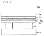
- Fig. 3 is a schematic cross section of the unit indicator lamp 10a of Fig. 2.
- a plurality of light sources (LED elements) 12 are arranged in a matrix inside a resin case 11 having a window W.
- Each light source 12 is mounted on a major surface of a print board and accommodated in the case 11. Its light-emitting part is exposed, facing upward in the case 11.
- An LED element which is a constituent of the light source 12 emits a light of a wavelength (the first wavelength) allocated to the unit indicator lamp 10a.
- a frame 13 is placed on the periphery of an upper surface of the window W.
- the frame 13 is fit into the housing 2 of Fig. 1 with the case 11 therebetween.
- a compound plate 20 is fit into the frame 13.
- the compound plate 20 has a layered structure consisting of four plates;
- the fluorescent plate 22 is provided in accordance with a main characteristic feature of the present invention.
- the fluorescent plate 22 receives the light of the first wavelength from the light source 12 and transmits part of the incident light towards the indicating surface (the upper side of this figure), and it emits a light of the second wavelength longer than the first wavelength from the rest of the incident light towards the indicating surface.
- Fig. 4 schematically shows this optical phenomenon.
- Fig. 4 is a schematic diagram showing optical characteristics of the fluorescent plate 22.
- the fluorescent plate 22 is obtained by mixing a fluorescent material (color changing coating) having fluorescent characteristics discussed later into a transparent resin material and forming the mixture in a sheet, a plate or the like.
- the reference sign FM of this figure shows the fluorescent material.
- the fluorescent material FM has the fluorescent characteristics of emitting the light L2 of the second wavelength (indicated by the wavy line of this figure) longer than the first wavelength when it returns to the ground state after it is excited by the light L1 of the first wavelength indicated by the solid line of this figure.
- the fluorescent characteristics will be discussed, taking a specific example in the exemplary experiment after the sixth preferred embodiment.
- the fluorescent plate 22 having such fluorescent characteristics as a whole, when the light L1 of the first wavelength from the light source 12 enters a light-incident surface 22a through the hologram diffusion plate 21, part of the incident light L1 goes out towards the indicating surface from a light-outgoing surface 22b as shown in this figure while the rest of the light L1 is absorbed in the fluorescent material FM and the light (fluorescence) L2 of the second wavelength longer than the first wavelength is emitted from the light-outgoing surface 22b.
- the lights of the first and second wavelengths projected from said fluorescent plate 22 is guided through the inscription plate 23 and the cover plate 24 towards the indicating surface, where an optical indication is thereby made.
- the color of light for optical indication (indication color) on the indicating surface side is defined by combination of the lights of the first and second wavelengths, in other words, combination of kinds of the light source 12 and the fluorescent plate 22, and therefore the optical indication can be made with any color by controlling this combination.
- This combination of the light source 12 and the fluorescent plate 22 will be discussed in the exemplary experiment after the sixth preferred embodiment, taking combination examples.
- the light-incident surface 22a and the light-outgoing surface 22b of the fluorescent plate 22 are opposed to each other and the fluorescent plate 22 is placed so that its light-incident surface 22a may face the light source 12. That produces the following effects.
- the hologram diffusion plate 21 is provided to diffuse the light from the light source 12 at a predetermined diffusion angle and thereafter project the diffused light to the fluorescent plate 22.
- This hologram diffusion plate 21 is provided with the diffusion surface (hologram surface) 21a utilizing light diffraction phenomenon on one-side surface of the transparent material, which can diffuse a light without attenuating it.
- the unit indicator lamp 10a can prevent the shape of the light source 12 from being externally recognized without providing an element for substantially absorbing or attenuating a light, such as a milky-white inscription plate.
- this preferred embodiment can achieve both "highly-intensified indication" and "high diffusibility of light” at the same time.
- the indicator lamp 10a of this preferred embodiment has only to use an LED element emitting a blue light as the light source 12 and the fluorescent plate 22 having fluorescence characteristics of emitting a yellow light (the light of the second wavelength) from part of the blue light (the light of the first wavelength) emitted from the light source 12.
- the light source 12 it is not necessary to use a package of LED elements emitting red, green and blue lights, for example, as the light source and an LED element emitting a single-color light can be used as the light source. That makes it possible to provide a white indicator lamp (surface-illuminated indicator device) at lower cost. Further, since the light source 12 needs less amount of heating values, it is possible to ensure longer lifetime of the indicator lamp without any problem on heating of the light source that would arise when the halogen lamp is used as the light source.
- the optical indication with white light can be made, providing a filter which transmits only a specified wavelength component in an appropriate position (e.g., a surface of the inscription plate 23) on a side of the light-outgoing surface 22b of the fluorescent plate 22 (Fig. 4) allows the indication color of the indicator lamp 10a to be changed into any color corresponding to the filter.
- the indicator lamp 10a comprising the light source 12 with blue LED element and the fluorescent plate 22 having fluorescence characteristics of emitting the yellow light from part of the blue light from the light source 12 can change the light for optical indication from white to a color defined substantially by the filter when additionally provided with a filter near the light-outgoing surface 22b of the fluorescent plate 22. Therefore, by appropriately changing the filter, the indication color of the indicator lamp 10a can be changed into any color.
- Fig. 5 is a perspective view showing an illuminated push-button switch to which the second preferred embodiment of the indicator device (surface-illuminated indicator device) in accordance with the present invention is applied.
- Fig. 6 is a partly-exploded perspective view of Fig. 5.
- Fig. 5 shows a case where an illuminated push-button switch 40 is attached to a panel 70 such as a control panel.
- the illuminated push-button switch 40 is of separate type, broadly consisting of an operation unit 60 and a contact unit 50.
- the operation unit 60 is inserted into a mounting hole 71 from the front side (operation side) of the panel 70.
- the contact unit 50 is connected to a waist portion 62 of the operation unit 60 on the rear side of the panel 70.
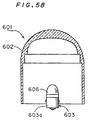
- the contact unit 50 internally has a switch contact, to which an LED unit light source4 54 is attached.
- the LED unit light source 54 is of substantially cylindrical-shaped and on its top portion arranged are a plurality of LED elements 54L.
- a ring 55 used for attaching the operation unit 60 to the panel 70 and a lock lever 53 used for fixing connection between the operation unit 60 and the contact unit 50 are separately provided.
- the contact unit 50 is electrically connected to a required apparatus through a terminal 52.
- the operation unit 60 consists of an operation unit body 61 and a push unit 80.
- an insert groove 62a is provided on the waist portion 62 of the operation unit body 61 so that a ledge 51a formed in an inner wall of the mounting hole 51H can be fit therein. Fitting the ledge 51a into the insert groove 62a, the waist portion 62 of the operation unit 60 is inserted into the mounting hole 51H of the contact unit 50.
- a projection (not shown) of the lock lever 53 disposed inside the ledge 51a rotates and the projection is thereby fitted into a fixing groove 62b provided orthogonally to the inserting groove 62a to connect and fix the operation unit 60 and the contact unit 50.
- an external thread 62S is formed on the waist portion 62 and is in threaded engagement with an internal thread surface 55s of the ring 55 to mount the operation unit body 61 on the panel 70.
- a rectangular receptacle 63 is formed in an upper portion of the operation unit body 61, into which the push unit 80 is accommodated.
- the push unit 80 will be discussed later in detail, when the push unit 80 is pushed down by hand after assembling, the push unit 80 open or close (on or off) a contact in the contact unit 50.
- the LED unit light source 54 is turned on or off in response to opening or closing of the contact. Alternately, as another constitution, the LED unit light source 54 may be turned on or off in response to a signal from an external apparatus (a controller or the like) connected to the illuminated push-button switch 40.
- An operation surface 80S of the push unit 80 is light-transmissible, and the characters and the like inside the operation surface 80s is illuminated by a light from the LED unit light source 54, thereby being externally recognized.
- Fig. 6 shows the explored push unit 80.
- a lower portion of the push unit 80 is a hollow base 81 having a transmission hole W1 and on this base layered are three plated in the following order;
- the LED unit light source 54 is so inserted as to be opposed to the diffusion plate 82 with the transmission hole W1 interposed therebetween.
- the LED unit light source 54 When the LED unit light source 54 is on, the light of the first wavelength from the LED elements 54L enters the light-incident surface 83a of the fluorescent plate 83 through the hologram diffusion plate 82. Part of the incident light goes on towards the indicating surface (upper side of this figure) while the rest of the incident light is changed in wavelength into the light of the second wavelength longer than the first wavelength by the fluorescent material (not shown) of the fluorescent plate 83. As a result, the lights of the first and second wavelengths are projected from the light-outgoing surface.
- the outgoing light of the first and second wavelengths goes through the inscription plate 84 and the front plate 85 in this order to make a surface-illuminated indication with the indication color defined by the first and second wavelengths on the indicating surface side.
- the color of the light for optical indication on the indicating surface side is defined by combination of the first and second wavelengths, in other words, combination of the kinds of the LED unit light source 54 and the fluorescent plate 83, it is possible to make an optical indication with any color by controlling the combination
- the light-incident surface 83a and the light-outgoing surface of the fluorescent plate 83 are opposed to each other and the fluorescent plate 83 is disposed so that the light-incident surface 83a may face the LED unit light source 54, it is possible to produce a visual effect as if the light-emitting surface might go up towards the indicating surface for the operator and thereby improve the viewability.
- hologram diffusion plate 82 allows achievement of "highly-intensified indication” and “high diffusibility of light” at the same time, like the first preferred embodiment.
- the indication color of the indicator lamp in the illuminated push-button switch allows the indication color of the indicator lamp in the illuminated push-button switch to be set white with less amount of heating values, like the first preferred embodiment.
- the illuminated push-button switch capable of making a white optical indication
- by additionally providing a filter near the light-outgoing surfer of the fluorescent plate 83 it is possible to change the color of the light for optical indication from white to a color substantially defined by the filter. Therefore, the indication color of the indicator lamp in the illuminated push-button switch can be changed to any color by appropriately changing the filter.
- Fig. 7 is a schematic cross section showing the third preferred embodiment of the indicator device (surface-illuminated indicator device) in accordance with the present invention.
- the surface-illuminated indicator device of this preferred embodiment is largely different from the first preferred embodiment of Fig. 4 in that a fluorescent body (wavelength changing member) consisting of two layered fluorescent plates 91 and 92 is provided to emit not only the light of the second wavelength but also a light of the third wavelength, instead of the single fluorescent plate 22 provided to emit the light of the second wavelength in the first preferred embodiment.
- Other basic constitution of the third preferred embodiment is the same as that of the first preferred embodiment.
- the fluorescent body 90 consists of the following two layered plates
- the fluorescent plate 91 first transmits part of the light L1 of the first wavelength towards the fluorescent plate 92, and fluorescent materials FM1 absorb the rest of the incident light L1 and each emit the light L2 of the second wavelength longer than the first wavelength towards the fluorescent plate 92.
- the fluorescent plate 92 receiving the lights L1 and L2 of the first and second wavelengths, projects part of the light L1 of the first wavelength and the whole light L2 of the second wavelength from a light-outgoing surface 90b of the fluorescent body 90 towards the indicating surface (upper side of this figure), and fluorescent materials FM2 absorb the rest of the light L1 of the first wavelength and each emit the light L3 of the third wavelength longer than the first wavelength to be projected from the light-outgoing surface 90b towards the indicating surface.
- the lights L1 to L3 of the first to third wavelengths make an optical indication entirely on the indicating surface.
- the fluorescent materials FM2 absorb part of the light L2 of the second wavelength and emit a light of the fourth wavelength (not shown) longer than the second wavelength to be projected from the light-outgoing surface 90b towards the indicating surface.
- the indication color on the indicating surface is defined by the lights L1 to L3 of the first to third wavelengths and the like, the indication color can be controlled more finely as compared with the first preferred embodiment where the indication color is defined by the lights L1 and L2 of two wavelengths.
- the light-incident surface 90a and the light-outgoing surface 90b of the fluorescent body 90 are opposed to each other and the fluorescent body 90 is disposed so that the light-incident surface 90a may face the LED unit light source 12, it is possible to produce a visual effect as if the light-emitting surface might go up towards the indicating surface for the operator and thereby improve the viewability, like the first and second preferred embodiments.
- the two fluorescent plates are layered to constitute the fluorescent body 90, more than two fluorescent plates may be layered to constitute the fluorescent body 90. Further, the fluorescent plates may be layered in any order.
- the fluorescent plates 22, 83, 91 and 92 are obtained by mixing the fluorescent material FM into a transparent resin material and forming the mixture in a sheet, plate or the like.
- most of the fluorescence created in the fluorescent plates goes inside the fluorescent plate, being guided to an end surface, and is released in density according to the law of total reflection. For this reason, the fluorescence projected from the light-outgoing surface towards the indicating surface tends to decrease in its amount.
- the fluorescence can be diffused inside the fluorescent plate and projected towards the indicating surface without being concentrated in the end surface.
- the light diffusion material absorbs the light to cause a loss which is an obstacle to highly-intensified indication.
- the other surface of the hologram diffusion plate 21 (the surface provided with the hologram surface 21a) is thinly coated with the fluorescent material FM and the coating film is used as a fluorescent plate 101.
- the fluorescent plate 101 thus obtained can efficiently project the fluorescence created inside the fluorescent plate 101 towards the indicating surface, without mixing the diffusion material therein.
- a transparent plate 102 is placed on the fluorescent plate 101 as shown in Fig. 9 and the transparent plate 102 and the hologram diffusion plate 21 sandwich the fluorescent plate 101.
- Fig. 10 is a schematic cross section showing the sixth preferred embodiment of the indicator device (surface-illuminated indicator device) in accordance with the present invention.
- This device is largely different from the device of the first preferred embodiment in that a fluorescent plate 111 having both functions of the fluorescent plate 22 and the inscription plate 23 of the first preferred embodiment is provided.
- the fluorescent plate 111 is obtained by mixing the fluorescent material and diffusion material into the transparent resin material and forming the mixture in a sheet, plate or the like, and on its surface inscribed are characters and signs to be represented.
- Other basic constitution of the sixth preferred embodiment is the same as that of the first preferred embodiment.
- the hologram diffusion plate 21 is disposed between the light source 12 and the fluorescent plate 22 in the first preferred embodiment, the hologram diffusion plate 82 is disposed between the LED unit light source 54 and the fluorescent plate 83 in the second preferred embodiment and the hologram diffusion plate 21 is disposed between the light source 12 and the fluorescent plate 111 in the sixth preferred embodiment, where the hologram diffusion plate is disposed is not limited to these and it may be disposed in any position on an optical path of the light going from the light source towards the indicating surface. With consideration of viewability, it is desirable that the hologram diffusion plate should be placed on a side of the light source relative to the fluorescent plate.
- the fluorescent plate since the light through the hologram diffusion plate is diffused at a predetermined angle and enters the fluorescent plate as a disperse light going in various directions to hit the fluorescent materials at high probability, the fluorescent plate entirely emits a light, to improve the viewability.
- the hologram diffusion plate is used as the light diffusion member to diffuse the tight going from the light source towards the indicating surface in the above preferred embodiments, a conventional well-known light diffusion plate may be used instead of the hologram diffusion plate.
- the light diffusion means such as the hologram diffusion plate is provided in the above preferred embodiments, since the light diffusion member has no effect on the indication color, the light diffusion member is not an essential constituent element for controlling the indication color but it is desirable to provide it in order for the operator to easily recognize the indication such as characters.
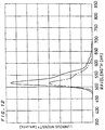
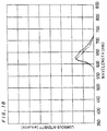
- Fig. 12 is a graph showing a fluorescence spectrum (one-dot chain line) from the green fluorescent plate when a light enters the green fluorescent plate from the blue LED element.
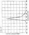
- Fig. 13 is a graph showing a fluorescence spectrum (one-dot chain line) from the orange fluorescent plate when a light enters the orange fluorescent plate from the blue LED element.
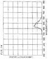
- Fig. 14 is a graph showing a fluorescence spectrum (one-dot chain line) from the red fluorescent plate when a light enters the red fluorescent plate from the blue LED element.
- the solid lines of Figs. 12 to 14 represent fluorescence spectra projected from the green, orange and red fluorescent plates, respectively, when a black light (ultraviolet light source) having a spectrum represented by the solid line of Fig. 11 enters the fluorescent plates.
- the light of the first wavelength from the blue LED element to the fluorescent plate
- the light (fluorescence) of the second wavelength longer than the first wavelength can be projected from the fluorescent plate.
- the lights of the first and second wavelengths are guided towards the indicating surface, to make an optical indication entirely on the indicating surface with an indication color defined by the combination of the first and second wavelengths.
- Fig. 16 is a graph showing a fluorescence spectrum (on-dot chain line) from the green fluorescent plate when the light enters the green fluorescent plate from the green LED element.
- Fig. 17 is a graph showing a fluorescence spectrum (on-dot chain line) from the orange fluorescent plate when the light enters the orange fluorescent plate from the green LED element.
- Fig. 18 is a graph showing a fluorescence spectrum (one-dot chain line) from the red fluorescent plate when the light enters the red fluorescent plate from the green LED element.
- the solid lines of Figs. 16 to 18 represent fluorescence spectra projected from the green, orange and red fluorescent plates, respectively, when the black light having a spectrum represented by the solid line of Fig. 15 enters the fluorescent plates.
- the blue LED element is prepared as the light source 12 in the indicator lamp (surface-illuminated indicator device) of Fig. 4 and a yellow fluorescent plate is prepared as the fluorescent plate 22.
- An experiment is made on an indication color for optical indication entirely on the indicating surface.
- Table 1 shows the indication color obtained by this combination.
- Columns "x" and “y” of this Table and following Tables 2 to 4 show x-component and y-component of chromaticity coordinates according to the CIEXYZ colorimetric system of color representation.
- the values of columns “x” and “y” represent x-component and y-component of a color of light emitted from the light source 12 or those of a color of light projected from the fluorescent plate 22, 91 or 92.
- a color of the light projected from the fluorescent plate 22 is the indication color on the indicating surface side and the color has the x-component of 0.287 and the y-component of 0.323.
- Table 2 shows the indication color when the blue LED element is used as the light source 12 and the green fluorescent plate is used as the fluorescent plate 22 in the indicator lamp (surface-illuminated indicator device) of Fig. 4.
- x y Light Source 12 Blue LED 0.133 0.149 Fluorescent Plate 22 Green Fluorescent Plate 0.409 0.555
- a color of the light projected from the fluorescent plate 22 is the indication color on the indicating surface side and the color has the x-component of 0.409 and the y-component of 0.555.
- the blue LED element is prepared as the light source 12 in the indicator lamp (surface-illuminated indicator device) of Fig. 7 and the yellow fluorescent plate and the red fluorescent plate are prepared as the fluorescent plates 91 and 92.
- An experiment is made on indication colors for optical indication entirely on the indicating surface.
- Table 3 shows the indication color obtained by this combination.
- a color of the light projected from the fluorescent plate 92 is the indication color on the indicating surface side and the color has the x-component of 0.428 and the y-component of 0.223.
- the blue LED element is prepared as the light source 12 in the indicator lamp (surface-illuminated indicator device) of Fig. 7 and the green fluorescent plate and the orange fluorescent plate are prepared as the fluorescent plates 91 and 92.
- An experiment is made on indication colors for optical indication entirely on the indicating surface in this combination.
- Table 4 shows the indication color obtained by this combination.
- x y Light Source 12 Blue LED 0.133 0.149 Fluorescent Plate 91 Green Fluorescent Plate 0.200 0.631 Fluorescent Plate 92 Orange Fluorescent Plate 0.445 0.517
- a color of the light projected from the fluorescent plate 92 is the indication color on the indicating surface side id the color has the x-component of 0.445 and the y-component of 0.517.
- Fig. 19 is a cross section showing the seventh preferred embodiment of the indicator device (surface-illuminated indicator device) in accordance with the present invention.
- the surface-illuminated indicator device (unit indicator lamp) 10a of this preferred embodiment is largely different from that of the first preferred embodiment of Figs. 2 and 3 in that a prism sheet 213 discussed later is used as the light diffusion member to further improve dispersive efficiency of light.
- an LED unit 212 is disposed and in an opening 212a of the case 211, the five following layered plates are fitted from a side of the LED unit 212;
- a level-difference portion 211b On an internal side wall of the opening 211a of the case 211, a level-difference portion 211b, being inwardly protruded. This level-difference portion 211b works to control the amount of insertion of the prism sheet 213, the fluorescent plate 214, the diffusion plate 215, and the inscription plate 216 and the cover plate 217 into the opening 211a.
- Fig. 20 is a plan view of the LED unit 212
- Fig. 21 is a side view thereof.
- a meshy cleat 212b to efficiently guide the light emitted from the LED elements 212a (light source) towards the indicating surface 218.
- Two LED elements 212a are placed in each of four LED placement regions surrounded by the cleat 212b. Sloping surfaces of the cleat 212b surrounding the four LED placement regions are reflecting surfaces to efficiently guide the light from the LED elements 212a towards the indicating surface 218.
- Each of the LED elements 212a emits the light of the first wavelength (herein, the light of blue wavelength). Further, the LED elements 212a are supplied with power through terminals 212c provided at the bottom of the LED unit 212.
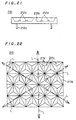
- Fig. 22 is a plan view showing the prism sheet 213 which is a characteristic feature of the present invention
- ad Fig. 23 is a cross section thereof.
- the prism sheet 213 is a member of square plate-like shape having a thickness of about 1 mm and made of a transparent resin such as acrylic resin.
- a light-incident surface 213a of the prism sheet 213 facing the LED unit 212 is flat and a light-outgoing surface 213b facing the indicating surface 218 is provided with a plurality of very small prisms 213c disposed without any clearance.
- each of the prisms 213c provided in the prism sheet 213 is of corner-cube obtained by cutting the corners of a rectangular solid so that the bottom surface may become a regular triangle as shown in Fig. 24. Therefore, each of upper three surfaces of the prism 213c is a prism surface 219 of isosceles triangle.
- the size S of the prism 213c is preferably not larger than several hundred ⁇ m, and more preferably not larger than several ten ⁇ m.
- the prisms 213c have the same size and are orderly arranged so that their prism surfaces 219 may face the indicating surface 218 and the regular-triangle bottom surfaces of adjacent prisms 213c may be in intimate contact with each other (in other words, the adjacent prisms 213c are in contact, sharing three sides of regular-triangle bottom surface).
- the light-outgoing surface 213b of the prism sheet 213 is thereby covered with a plurality of prisms 213c without any clearance.
- the optical characteristics of the prism sheet 213 will be discussed.
- a light L emitted from the LED elements 212a enters a center portion C of adjacent six prisms 213b through the light-incident surface 213a, as shown in Fig. 22, the incident light L is dispersed in six directions by refraction or the like in the prism sheet 213 and then projected out. Therefore, viewed from the side of the light-outgoing surface 213b through the prism sheet 213, one LED element 212a looks as if there are six ones.
- the fluorescent plate 214 made of a transparent resin is obtained by mixing the fluorescent material which receives the light of the first wavelength and emits the light (fluorescence) of the second wavelength longer than the first wavelength into the base material.
- the fluorescent material which receives the light of blue wavelength (the first wavelength) and emits the light of yellow wavelength (the second wavelength) is mixed therein.
- the fluorescent plate 214 has a light-incident surface receiving a light from the LED unit 212 and a light-outgoing surface facing the indicating surface 218.
- the fluorescent plate 214 receives a light from the LED unit 212 and a light-outgoing surface facing the indicating surface 218.
- the light of blue wavelength from the LED unit 212 enters the fluorescent plate 214 through the light-incident surface, part of the incident light goes through the fluorescent plate 214 and the rest of the light is changed into a light of yellow wavelength to go out from the fluorescent plate 214.
- a white color made from the lights of blue wavelength and yellow wavelength is projected from the light-outgoing surface of the fluorescent plate 214 and the white light is used as the indication light.
- the diffusion plate 215 is obtained by mixing an inorganic or organic material for diffusing a light into a base material of resin. The light entering the diffusion plate 215 is therefore diffused and projected.
- the inscription plate 216 made of transparent resin is inscribed with characters and signs to be represented through printing, engraving or the like.
- a diffusion material for diffusing a light may be mixed into the fluorescent plate 214, instead of using the diffusion plate 215, so that the fluorescent plate 214 may have a light diffusion function.
- the light emitted from the LED elements 212a of the LED unit 212 enters the prism sheet 213, being dispersed, and enters the fluorescent plate 214. Since the prism sheet 213 has a function of dispersing the incident light into six directions as mentioned above, a small number of LED elements 212a can produce the same effect as a large number of LED elements 212a irradiating the fluorescent plate 214 with light, and the amount of light entering the fluorescent plate 214 is uniform on its light-incident surface. This device uses eight LED elements 212a and produces the same effect as forty-eight LED elements irradiating the fluorescent plate 214 with light.
- the light entering the prism sheet 213 is refracted and multidirectionally dispersed inside the prism sheet 213 and goes out from the prism sheet 213 at divergent-directional angle. Therefore, the light from the LED elements 212a can enter a peripheral portion of the fluorescent plate 214 shadowed by the level-difference portion 211b in the opening 211a of the case 211.
- the fluorescent plate 214 projects the white light to be used as the indication light as discussed above.
- the white indication light enters the diffusion plate 215, being diffused to be further uniform, and projected from the indicating surface 218 in the outer surface of the cover plate 217 through the inscription plate 216, with uniform amount of light and uniform color, to make a two-dimensional representation on the indicating surface 218.
- the information inscribed on the inscription plate 216 is represented with white indication light.
- the light from the LED elements 212a can be projected to the peripheral portion 214a of the fluorescent plate 214 shadowed by the level-difference portion 211b in the opening 211a of the case 211.
- variation in the amount of light caused by less number of LED elements 212a to be provided as compared with the areas of the fluorescent plate 214 and indicating surface 218 and the reflection of the cleat 212b in the LED unit 212 and the like can be cut and a uniform amount of light can be applied entirely on the fluorescent plate 214 with less number of LED elements 212a. That prevents variation in the amount of light and color of the white indication light on the indicating surface 218, to achieve an excellent indication.
- the white indication light projected from the fluorescent plate 214 is further uniformed by the diffusion plate 215, more highly-uniformed indication light can be achieved.
- the prism sheet 213 is made of resin, it is suitable for mass production and can be manufactured at lower cost.
- indication lights of various colors may be obtained by controlling the combination of the light of the first wavelength emitted from the LED elements 212a and the light of the second wavelength emitted from the fluorescent plate 214, like the first preferred embodiment.
- the fluorescent plate 214 is used as the indication light by cutting the light of blue wavelength emitted from the LED elements 212a and providing a filter for transmitting only the light emitted from the fluorescent material in the fluorescent plate 214 between the fluorescent plate 214 and the indicating surface 218. That makes it possible to purely extract the color of the light emitted from the fluorescent plate 214 as the color of the indication light.
- the collective indicator lamp 1 of Fig. 1 is constituted of a plurality of unit indicator lamps 10a, 10b, ..., 10i
- the LED unit 212 is formed in a form of one board and its indicating surface portion is divided as shown in Fig. 1 on which the inscription plate and the like are placed.
- Fig. 25 is a cross section showing the unit indicator lamp 10a to which a second preferred embodiment of the indicator device in accordance with the present invention is applied.
- the indicator lamp 10a has a constitution where the fluorescent plate 214 is omitted in the indicator lamp 10a of the seventh preferred embodiment. Elements which correspond to those of the indicator lamp 10a shown in Fig. 19 are given the same reference signs and will not be discussed.
- the indicator lamp 10a of this preferred embodiment since the light from the LED unit 212 is guided through the prism sheet 213 towards the indicating surface 218, uniform amount of light from the LED unit 212 can be projected from the whole indicating surface 218, to produce the same effect as the seventh preferred embodiment, of an excellent indication without variation and the like.
- Fig. 26 is a cross section showing the unit indicator lamp 10a to which the ninth preferred embodiment of the indicator device in accordance with the present invention is applied
- Fig. 27 is a plan view of an LED unit 241 included in the indicator lamp 10a.
- the indicator lamp 10a has the same constitution as that of the eighth preferred embodiment except that it uses the LED unit 241 comprising three kinds of LED elements 242, 243 and 244 emitting lights of red, green and blue wavelengths, and corresponding elements are given the same reference signs ad will not be discussed.
- the LED unit 241 of this preferred embodiment as shown in Fig. 27, three elements for each of the three kinds of LED elements 242, 243 and 244 are arranged in matrix inside each of four LED placement regions surrounded by the meshy cleat 212b on its upper surface.
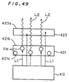
- Fig. 28 is a circuit diagram of the LED unit 241, where the three kinds of LED elements 242, 243 and 244 are connected in parallel to a DC power supply 245 and variable resistors 246, 247 and 248 (current controlling unit) and protection resistors 249, 250 ad 251 are connected between the DC power supply 245 and the LED elements 242, 243 and 244, respectively. Therefore, by changing resistance values of the variable resistors 246, 247 and 248, current values to be supplied for the LED elements 242, 243 and 244, respectively, can be independently controlled.
- LED element 242 (243, 244) is connected to the variable resistor 246 (247, 248) in the illustration of Fig. 28, a plurality of LED elements 242 (243, 244) may be connected in series. Further, the constituent elements in the circuit configuration of Fig. 28 other than the DC power supply 245 are placed inside the LED unit 241 and the DC power supply 245 are placed outside the indicator lamp 10a.
- Fig. 29 is a cross section showing part of the unit indicator lamp 10a where the variable resistors 246, 247 and 248 are provided
- Fig. 30 is a bottom view thereof.
- the variable resistors 246, 247 and 248 and the protection resistors 249, 250 and 251 are placed on the back side of a substrate 253 provided in the case 252 of the LED unit 241 for providing the LED elements 242, 243 and 244.
- variable resistors 246, 247 and 248 are provided with rotary shafts 246a, 247a and 248a, and through holes 211c and 252c are provided therefor on bottom surfaces of the cases 211 and 252 of the indicator lamp 10a and the LED unit 241 so that the rotary shafts 246a, 247a and 248a can be externally controlled with a minus driver and the like. Further, the variable resistors 246, 247 and 248 may be placed outside the indicator lamp 10a, being connected with wires.
- the indicator lamp 10a thus constituted, a light obtained by superposing the lights emitted by the red, green and blue LED elements 242, 243 and 244 is used as the indication light. Therefore, the color of the indication light can be changed to any color such as white by changing each of the resistance values of the variable resistors 246, 247 and 248 to control the value of current to be supplied for each of the three kinds of LED elements 242, 243 and 244 and control the amount of light emitted from each of the three kinds of LED elements 242, 243 and 244.
- the light emitted from the LED elements 242, 243 and 244 enters the prism sheet 213, being sufficiently dispersed to be uniform, and enters the diffusion plate 215 as the indication light of uniform amount and uniform color, being diffused to be further uniform. After that, the light goes through the inscription plate 216 and is projected from the whole indicating surface 218 of the cover plate 217.
- this preferred embodiment produces an effect of obtaining the indication light of any color only by controlling the resistance values of the variable resistors 246, 247 and 248 and also produces the same effect as the seventh preferred embodiment, of preventing variation in amount of light and color of the indication light to achieve an excellent indication and the like.
- this preferred embodiment has the constitution to achieve the indication light of desired color by controlling the current values with the variable resistors 246, 247 and 248 to control the amount of light emitted from the LED elements 242, 243 and 244, the color of the indication light can be easily controlled.
- variable resistors 246, 247 and 248 can be externally controlled, it is easy to control the resistance value, and since the resistance value can be controlled while observing the indicating condition, it is easy to make a fine-tuning of color tone and the like of the indication light.
- Fig. 31 is a block diagram showing a LED unit provided in a indicator lamp to which the tenth preferred embodiment of the indicator device In accordance with the present invention is applied.
- the indicator lamp has the same constitution as the indicator lamp 10a of the ninth preferred embodiment discussed earlier except that current controllers 262, 263 and 264 are provided for changing the value of the current to be supplied for the LED elements 242, 243 and 244 in response to instructions from a control unit 261, instead of the variable resistors 246, 247 and 248, and corresponding elements are given the same reference signs and will not be discussed.
- plural kinds of colors for the indication light to be produced are each registered in the control unit 261 beforehand with data indicating the values of currents to be supplied to the LED elements 242, 243 and 244 in generation of the indication light of the color.
- the control unit 261 externally receives an instruction corresponding to a desired color, to determine the color of the indication light to be produced among the plural kinds of colors on the basis of the received instruction.
- the control unit 261 controls the values of currents to be supplied for the LED elements 242, 243 and 244 through the current controllers 262, 263 and 264, respectively, based on the data registered beforehand and thereby adjusts the ratio of the amounts of lights emitted from the LED elements 242, 243 and 244, to obtain the indication light of predetermined color.
- This embodiment produces an effect of automatically obtaining the indication light of predetermined color without specially controlling the variable resistors 246, 247 and 248 as well as the effect of the ninth preferred embodiment to obtain the indication light of any color while preventing variation in the amount of light or color and so on.
- each of the prisms 213c provided on the light-outgoing surface 213b of the prism sheet 213 is of corner-cube in the seventh to tenth preferred embodiments, its shape is not limited to the corner-cube, but may be other polypyramid such as general triangular pyramid, rectangular pyramid, hexagonal pyramid and the like only if the prisms 213c can cover the light-outgoing surface 213b without any clearance.
- the inscription plate 216 is provided on a side of the diffusion plate 215 facing the indicating surface 218 in the seventh to tenth preferred embodiments, it may be provided on a side of the diffusion plate 215 facing the LED units 212 and 241.
- the inscription plate 216 is used in the seventh to tenth preferred embodiments, the inscription plate 216 may be removed and the information can be transmitted by turning on and off or blinking the indicator lamp 10a.
- the prisms 213c on the light-outgoing surface 213b of the prism sheet 213 are exposed in the surface in the seventh to tenth preferred embodiments, the prisms 213c may be covered with a transparent resin with an index of refraction lower than that of the prism sheet 213.
- the indicator device of the present invention is applied to the indicator lamp in the seventh to tenth preferred embodiments, it can be applied to the illuminated push-button switch in which a pushing operation unit is turned on in response to the on/off state.
- the indicator lamp 10a of the seventh to tenth preferred embodiments is used as an illuminating device.
- an illumination is made by using a light projected two-dimensionally from the whole indicating surface 218 (light-projected surface) and the light projected from the indicating surface 218 with no variation can make an excellent illumination.
- the inscription plate 216 is removed.
- the fluorescent plate has a characteristic feature of changing part of received light (the light of the first wavelength) having a wavelength shorter than its intrinsic fluorescent wavelength to the light having the fluorescent wavelength (the light of the second wavelength), it has a property of transmitting a received light having a wavelength longer than the fluorescent wavelength without substantially changing its wavelength.
- an additively-mixed color of the light of shorter wavelength and the fluorescent wavelength serves as the indication light when the light of shorter wavelength enters the fluorescent plate and the light of longer wavelength itself serves as the indication light when the light of longer wavelength enters the fluorescent plate. Further, when both the light of shorter wavelength and the light of longer wavelength enter the fluorescent plate, the mixed color of the light of shorter wavelength, the light of fluorescent wavelength and the light of longer wavelength.
- switching these lights allows switching of the indication light among a plurality of colors.
- a yellow light is obtained as the light of the second wavelength and an almost pure white is also obtained as the additively-mixed color of them.
- the white light has no variation from pure white caused by time-varying deterioration of the emitter of specific color and a time-varying deterioration of the blue emitter would cause a deterioration only in luminance. Therefore, including the pure white as one of a plurality of indication lights which can be switched in the present invention has a special significance.
- Fig. 32 is a explored perspective view of the unit indicator lamp 10a to which the twelfth preferred embodiment of the indicator device (surface-illuminated indicator device) in accordance with the present invention is applied.
- Fig. 33 is a schematic cross section of the unit indicator lamp 10a of Fig. 32.
- a plurality of light sources 312 (four LED units in this figure) are arranged in a matrix inside a resin case 311 having the window W.
- Each of the light sources 312 is mounted on a major surface of the print board and accommodated in the case 311 of Fig. 32, and its light-emitting part is exposed towards the upper surface of the case 311.
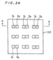
- Each of the light sources 312 is constituted of a plurality of kinds of emitters S1 and S2 (a plurality of kinds of LED elements) having different emission colors which are alternately arranged in a matrix as shown in Fig. 34.
- the first emitter S1 is a blue LED which generates a light of blue wavelength as the first wavelength.
- the second emitter S2 is a red LED which generates a light of red wavelength as a light of a wavelength different from the first wavelength.
- Fig. 35 is a schematic view including the A-A section of the light source 312 (LED unit) of Fig. 34.
- Switches S1 and S2 are supplied in parallel with the power from a power supply PW.
- To the first switch SW1 each of the first emitters S1 among the two kinds of emitters S1 and S2 constituting the light source 312 is electrically connected.
- To the second switch SW2, each of the second emitter S2 is electrically connected.
- a frame 313 is disposed in an upper periphery of the window W shown in Fig. 32.
- the frame 313 is fit in the housing 2 of Fig. 1 with the case 311 therebetween, and a compound plate 320 is fit into the frame 313.
- the compound plate 320 is constituted of superposed four plates:
- the fluorescent plate 322 has the same structure as the fluorescent plate 22 of the first preferred embodiment.
- the fluorescent plate 322 receives the light L1 of the first wavelength from the first emitter S1 of the light source 312, it transmits part of the received light towards the indicating surface (upper side of this figure) and emits the light L2 of the second wavelength longer than the first wavelength from the rest of the received light and projects the light L2 of the second wavelength towards the indicating surface (see Fig. 36).
- the fluorescent plate 322 having the fluorescent characteristics as a whole, when the light L1 of the first wavelength from the light source 312 is projected to a light-incident surface 322a through the hologram diffusion plate 321, part of the incident light L1 is projected from the light-outgoing surface 322b towards the indication side, and the rest of the incident light L1 is absorbed in the fluorescent material FM and the light L2 (fluorescence) of the second wavelength longer than the first wavelength is emitted from the light-outgoing surface 322b as shown in Fig. 36.
- the fluorescent plate 322 has no substantial wavelength changing function for the light having a wavelength longer than its intrinsic fluorescent wavelength.
- a wavelength longer than both the first wavelength and the intrinsic fluorescent wavelength (the second wavelength) of the fluorescent plate 322 is selected as another wavelength, when only the light L0 of another wavelength is projected from the light source 312 as shown in Fig. 37, the light L0 of another wavelength substantially goes through the fluorescent plate 322. Therefore, in this case, there arises no color change with wavelength change.
- an input light Lin a light projected to the fluorescent plate 322
- an output light Lout a light projected from the fluorescent plate 322
- an input light Lin a light projected to the fluorescent plate 322
- an output light Lout a light projected from the fluorescent plate 322
- indication light Ld a light actually recognized on the indicating surface
- the output light Lin projected from the fluorescent plate 322 is guided through the inscription plate 323 and the cover plate 324 towards the indicating surface, serving as the indication light Ld to make an optical indication.
- the indication light Ld has substantially the same wavelength component (color) as the output light Lout.
- the color (indication color) of the indication light Ld for optical indication on the indicating surface side can be switched among the following three colors:
- the indicator lamp of this preferred embodiment has a great advantage of generating colors which can not be achieved only by the first emitter S1 by utilizing the selective wavelength changing function of the fluorescent plate 322 without exerting a substantial influence on the indication color obtained by the second emitter S2.
- the combination of the first emitter S1 and the fluorescent plate 322 utilizing the selective wavelength changing function will be discussed in the exemplary experiments, taking specific examples.
- the hologram diffusion plate 321 is provided to diffuse the light from the light source 312 at a predetermined angle and then the diffused light is projected to the fluorescent plate 322.
- the hologram diffusion plate 321 which has the diffusion surface (hologram surface) 321a utilizing light diffraction on one side of the transparent member, can make a diffusion of light without attenuating the light. Therefore, the unit indicator lamp 10a can prevent external recognition of the shape of the light source 312 without providing any element for substantially absorbing or attenuating light like a milky-white inscription plate. In short, this preferred embodiment can achieve "highly-intensified indication" and "uniform diffusibility of light” at the same time.
- the unit indicator lamp 10a of this preferred embodiment has only to use the LED element which emits a blue light as the first emitter and the fluorescent plate 322 having the fluorescent characteristics of emitting a yellow light (the light of the second wavelength) from part of the blue light (the light of the first wavelength) emitted from the first emitter S1. In this case, it is not necessary to use a light source packaging the LED elements for emitting red, green and blue lights in order to obtain white.
- the light source 312 has little amount of heating values, it is possible to ensure longer lifetime of the indicator lamp for making an optical indication of white color without any problem on heating of the light source that would arise when the halogen lamp is used as the light source. Further, the time-varying deterioration of the first emitter S1 would cause only deterioration of luminance and would not cause the color of the indication light Ld to vary from the pure white.
- red light can be used, for example, as the light of another wavelength.
- a switching of the indication color can be made among three colors, i.e., pure white, red and pink.
- circuits serve as luminance changing part for changing the luminaces of the first and second emitters S1 and S2 depending on their emitting condition.
- the supply voltage is lowered in the lighting of both the emitters in the circuit of Fig. 39, it should be appropriately determined, in consideration of visual effect of the indication color, whether in the lighting of one emitter or in the lighting of both emitters the respective luminances of the emitters are increased.
- the present invention can be applied to a switching of the indication color among a plurality of kinds of chromatic colors as well as the switching among a plurality of colors including white.
- a combination of the first emitter S1 and the fluorescent plate 22 is selected so that the mixed color of the fist and second wavelengths may be the first chromatic color.
- the light of another wavelength emitted from the second emitter S2 is determined to be a light of the second chromatic color.
- both the first and second emitters S1 and S2 are turned on, the light of the first chromatic color and the light of the second chromatic color are additively mixed to obtain a light of the third chromatic color as the indication color light.
- Specific examples of switchings between chromatic colors will be discussed in detail later, and such a constitution can be applied to the thirteenth and fourteenth preferred embodiments as well as the twelfth preferred embodiment.
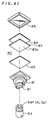
- Fig. 40 is a perspective view showing a illuminated push-button switch to which the thirteenth preferred embodiment of the indicator device in accordance with the present invention is applied
- Fig. 41 is a partly-exploded perspective view of Fig. 40.
- the illuminated push-button switch of this preferred embodiment has substantially the same constitution as the illuminated push-button switch of the second preferred embodiment except that it uses an LED unit light source 54 having a different constitution, and corresponding elements are given the same reference signs and will not be discussed.
- a group of emitters 54P provided on a top portion of the LED unit light source 54 are constituted of the first emitters S1 (LED elements of the first wavelength) and the second emitters S2 (LED elements of another wavelength) which are alternately disposed.
- the LED unit light source 54 is inserted so as to be opposed to the diffusion plate 82 with the transmission hole W1 therebetween. Hence, when only the first emitter S1 of the LED unit light source 54 is turned on, the light of the first wavelength from the LED element 54P is projected onto the light-incident surface 83a of the fluorescent plate 83 through the hologram diffusion plate 82. Part of the incident light goes towards the indicating surface (the upper side of this figure) while the rest of the incident light is projected to the fluorescent material (not shown) of the fluorescent plate 83 ad changed in wavelength to the light of the second wavelength longer than the first wavelength. Then, from the light-outgoing surface, the lights of the first and second wavelengths are projected out. The outgoing lights of the first and second wavelengths go through the inscription plate 84 and the front plate 85 and make a surface-illuminated indication with indication colors defined by the first and second wavelengths on the indicating surface side.
- the light of another wavelength serves as the indication light to make a surface-illuminated indication on the indicating surface side.
- the mixed light of the light of the first wavelength, the light of the second wavelength and the light of another wavelength is projected out from the indicating surface side.
- the thirteenth preferred embodiment like the twelfth preferred embodiment, by utilizing the selective wavelength changing function of the fluorescent plate 83, it is possible to generate colors which can not be achieved only by the first emitter S1 without exerting a substantial influence on the indication color of the second emitter S2.
- hologram diffusion plate 82 allows achievement of "highly-intensified indication” and "uniform diffusibility of light” at the same time, like the twelfth preferred embodiment, as compared with use of the prior-art well-known light diffusion plate.
- the LED element which emits a blue light is used as the first emitter S1 and the fluorescent plate having the fluorescent characteristics of emitting a yellow light from part of the blue light emitted from the first emitter S1 is used as the fluorescent plate 83, like the twelfth preferred embodiment, it is possible to set the indication color of the indicator lamp in the surface-illuminated push-button to white with less amount of heating values.
- Fig. 42 is a schematic cross section showing the fourteenth preferred embodiment of the indicator device (surface-illuminated indicator device) in accordance with the present invention.
- the surface-illuminated indicator device of this preferred embodiment is different from that of the twelfth preferred embodiment of Fig. 36 largely in that a fluorescent body 390 (wavelength changing member) constituted of two layered plates, i.e., fluorescent plates 391 and 392, is provided to emit the light of third wavelength as well as the second wavelength, instead of providing the single fluorescent plate 322 to emit the light of the second wavelength.
- a fluorescent body 390 wavelength changing member
- Other basic constitution of the fourteenth preferred embodiment is the same as that of the twelfth preferred embodiment.
- the fluorescent body 390 has the following two layered plates:
- part of the light L1 of the first wavelength and the light L2 of the second wavelength are projected from a light-outgoing surface 390b of the fluorescent body 390 towards the indicating surface (the upper side of this figure), and the rest of the light L1 of the first wavelength is absorbed in the fluorescent materials FM2 and the light L3 of the third wavelength longer than the first wavelength is emitted from each of the fluorescent materials FM2 and projected from the light-outgoing surface 90b towards the indicating surface.
- a optical indication with the lights L1 to L3 of the first to third wavelengths is made entirely on the indicating surface.
- part of the light L2 of the second wavelength is absorbed in the fluorescent materials FM2, and a light of the fourth wavelength (not shown) longer than the second wavelength is emitted from the fluorescent materials FM2 and projected from the light-outgoing surface 90b towards the indicating surface.
- the fourteenth preferred embodiment can make a finer control of the indication color than the twelfth preferred embodiment in which the indication color is defined by the lights L1 and L2 of two wavelengths.
- the indication color is the color of another wavelength emitted from the second emitter S2 (Fig. 43), and when both the first and second emitters S1 and S2 are simultaneously turned on, the indication color is the mixed color of the colors of the lights L1 to L3 of the first to third wavelengths and the color of another wavelength (Fig. 44).
- fluorescent plates 391 and 392 are layered to constitute the fluorescent body 390
- three or more fluorescent plates can be layered to constitute the fluorescent body 390. Further, the fluorescent plates can be layered in any order.
- the hologram diffusion plate 321 is disposed between the light source 312 and the fluorescent plate 322 in the twelfth preferred embodiment and the hologram diffusion plate 382 is disposed between the LED unit light source 54 and the fluorescent plate 83 in the thirteenth preferred embodiment
- the position of the hologram diffusion plate is not limited to these, ad the hologram diffusion plate may be disposed anywhere on the optical path of the light going from the light source towards the indicating surface. It is desirable, however, that the hologram diffusion plate should be placed on a side of the light source relative to the fluorescent plate in consideration of viewability.
- the hologram diffusion plate When the hologram diffusion plate is disposed thus, the light going through the hologram diffusion plate is projected into the fluorescent plate as a disperse light which is diffused at a predetermined angle and goes in various directions, to impinge on the fluorescent material with higher probability, and therefore a emission using the whole fluorescent plate is achieved to improve the viewability.
- the hologram diffusion plate is used as a light diffusion member for diffusing the light going from the light source towards the indicating surface in the above
- the conventional well-known light diffusion plate or the prism sheet 213 used in the seventh preferred embodiment may be used, instead of the hologram diffusion plate.
- the light diffusion member such as the hologram diffusion plate is provided in the above preferred embodiments, the light diffusion member is not an indispensable element to control the indication color since the light diffusion member has no effect on the indication color. In order that an operator can easily recognize indication such as characters, however, it is desirable to provide the light diffusion member.
- a filter near the light-outgoing surface of the fluorescent plate allows a change of the light color for optical indication.
- the indicator lamp or the illuminated push-button switch capable of making an optical indication of pure white as one of the indication colors
- the indication color is changed into one using the light spectrum extracted through the filter among the light spectra projected from the fluorescent plate.
- the indication color corresponding to another wavelength is changed depending on the color of the filter. For example, when a red light is used as the light of another wavelength ad a yellow filter is used as a filter, a switching among three colors, i.e., yellow, a mixed color of yellow and red and a mixed color of yellow and pink.
- first and second emitters S1 and S2 emitters which generate two lights having wavelengths shorter than the fluorescent wavelength of the fluorescent plate and different from each other may be used. For example, when a yellow fluorescent plate is used, a blue emitter ad a green emitter which have wavelengths shorter than that of yellow. When any one of the emitters is turned on, part of the light is changed in wavelength to obtain an indication color different from the emission color of the emitter.
- the number of kinds of emitters incorporated in the light source is not limited to two, and three or more kinds of emitters may be incorporated. In this case, one or more kinds of emitters are used as emitters for generating a light to be changed in wavelength by the fluorescent plate.
- the twelfth to fourteenth preferred embodiments show the constitution where the second emitter S2 for emitting a light of another wavelength is additionally provided in the light source of the first to third preferred embodiments, there may be a constitution where the second emitter S2 is additionally provided in the light source of the fourth to sixth preferred embodiments.
- the kinds of colors of the indication lights obtained by the combination of the light of the first wavelength emitted by the first emitter S1 and the light of the second wavelength emitted by the fluorescent plate 322 which receives the light of the first wavelength when only the first emitter S1 is turned on among the first and second emitters S1 and S2 in the light source are the same as those of the first to sixth preferred embodiments, and no discussion will be made thereon.
- the wavelength changing unit TW of Fig. 45 is constituted of a yellow fluorescent plate 322Y like the yellow fluorescent plate 22 of Table 1, a milky-white diffusion plate 321D and a transparent cover plate 324, and the wavelength changing unit TG of Fig. 46 is constituted of a green fluorescent plate 322G like the green fluorescent plate of Table 2, the milky-white diffusion plate 321D and the transparent cover plate 324.
- these wavelength changing units TW and TG are not altogether the same as the constitution of Fig. 32, a color changing function by combination of the blue emitter S1 and the fluorescent plate 322Y or 322G can be sufficiently understood from a measurement result using the wavelength changing unit TW or TG.
- this graph shows respective indication color spectra of three cases, i.e., use of a blue LED element 312B as the light source, use of a red LED element 312R and use of an amber LED element 312A.
- the blue LED element 312B has the same emitting spectrum as the blue LED elements of Tables 1 and 2.
- the blue LED element 312B when the blue LED element 312B is turned on, an almost flat spectrum is obtained in a wide range of 400 nm to 650 nm and an almost pure white indication color is achieved.
- the fluorescent plate 322Y has a yellow fluorescent color, and the yellow fluorescent color has such a wide spectrum range that it becomes almost pure white when mixed with a blue light.
- the blue LED element 312B is used as the first emitter S1 and the amber LED element 312A is used as the second emitter S2, a switching can be made among the three kinds of colors, i.e., pure white, amber and whity-amber.
- the blue LED element 312B is used as the first emitter S1 and the red LED element 312R is used as the second emitter S2, a switching can be made among the three kinds of colors, i.e., pure white, red and whity-red (that is, pink).
- this graph shows indication color spectra by the green fluorescent plate 322G in respective cases where the three kinds of emitters like in Fig. 45 are turned on.
- the blue LED element 312B is turned on, a pure green indication color having a peak near 510 nm is achieved. This green is purer than the green generated by the green LED element.
- the amber LED element 312A is turned on, a spectrum having a peak near 600 nm is obtained and an amber indication color which is almost the same as the input light is achieved.
- the red LED element 312R is turned on, a spectrum having a peak near 650 nm is obtained and a red indication color which is almost the same as the input light is achieved.
- the blue LED element 312B is used as the first emitter S1 and the amber LED element 312A is used as the second emitter S2
- a switching can be made among the three kinds of colors, i.e., pure green, amber and additively-mixed color of green and amber.
- the blue LED element 312B is used as the first emitter S1 and the red LED element 312R is used as the second emitter S2
- a switching can be made among the three kinds of chromatic colors, i.e., pure green, red and additively-mixed color of red and green (broadly, a color raging from a yellow region to an orange region).
- the optical characteristics of the fluorescent plate to change part of the light of the first wavelength into the light of the second wavelength longer than the first wavelength while substantially transmitting the light having a wavelength longer than the intrinsic fluorescent color, it is possible to switch the indication color among a plurality of colors.
- a light source having two kinds of LED elements i.e., the LED element emitting an ultraviolet light and that emitting a blue light
- a light generated by selectively turning these LED elements is projected through a yellow fluorescent plate.
- the LED element emitting the ultraviolet light is turned on, part of the generated ultraviolet light is changed into a yellow light through the fluorescent plate and the rest of the light goes through the fluorescent plate as the unchanged ultraviolet light. Since the ultraviolet light is invisible as well known, an externally observable color is yellow when only the LED element emitting the ultraviolet light is turned on.
- a switching of the indication light can be made between yellow and blue.
- Fig. 47 is a explored perspective view of the unit indicator lamp 10a to which the fifteenth preferred embodiment of the indicator device (surface-illuminated indicator device) in accordance with the present invention is applied.
- Fig. 48 is a schematic cross section of the unit indicator lamp 10a of Fig. 47.
- a plurality of light sources 412 LED elements
- Each of the light sources 412 is mounted on the major surface of the print board and accommodated in the case 411, and its light-emitting part is exposed towards the upper surface of the case 411.
- the LED elements constituting the light source 412 each emit a light of any one of wavelengths ranging from the ultraviolet region to blue (the first wavelength), herein a light of blue wavelength.
- a frame 413 is disposed in an upper periphery of the window W.
- the frame 413 is fit in the housing 2 of Fig. 1 with the case 411 therebetween, and a compound plate 420 is fit into the frame 413.
- the compound plate 420 is constituted of five layered plates:
- the fluorescent plate 421 and the filter 423 are provided in accordance with a main characteristic feature of the present invention.
- the fluorescent plate 421 has a light-incident surface 421 a receiving a light from the light source 412 and a light-outgoing surface 421b facing the indicating surface (the upper side of this figure).
- the fluorescent plate 421 receives a light of the first wavelength incident through the light-incident surface 421a and emits a light of the second wavelength longer than the first wavelength to be projected from the light-outgoing surface 421b.
- the filter 423 removes the light of the first wavelength which goes through the fluorescent plate 421 among the light projected from the light-outgoing surface 421b of the fluorescent plate 421 and substantially transmits only the light of the second wavelength. This optical phenomenon is schematically shown in Fig. 49.
- Fig. 49 is a schematic diagram showing optical characteristics of the fluorescent plate 421 and the filter 423.
- the fluorescent plate 421 has the same structure as the fluorescent plate 22 of the first preferred embodiment, and corresponding elements are given the same reference signs and discussion will be omitted thereon.
- the filter 423 removes the light L1 of the first wavelength which goes through the fluorescent plate 421 and transmits only the light L2 of the second wavelength towards the indicating surface as the indication light.
- the light L1 of the first wavelength projected to the filter 423 is sufficiently attenuated until it reaches a surface 423a of the filter 423 on the side of the indicating surface, not going through the filter 423 while the light L2 of the second wavelength is hardly attenuated to go through the Filter 423. Therefore, a light made of the light L2 of the second wavelength is projected from the surface 423a of the filter 423.
- the fluorescent plate 421 receiving the light of the first wavelength emits the light of the second wavelength.
- the light of the second wavelength and the light of the first wavelength which goes through the fluorescent plate 421 are projected into the filter 423 through the inscription plate 422.
- the filter 423 removes the light of the first wavelength among the lights of the first and second wavelengths and only the light of the second wavelength is substantially projected from the surface 423a of the filter 423.
- the light of the second wavelength which goes through the filter 423 is guided towards the indicating surface through the milky-diffusion plate 424 and the cover plate 425, to make a optical indication.
- the indicator lamp 10a surface-illuminated indicator device of this preferred embodiment can purely take the color of the light of the second wavelength emitted by the fluorescent plate 421 as the color of the light for optical indication.
- a color of light with higher chroma can be obtained as compared with, for example, a method of obtaining a desired color light by superposing a plurality of kinds of lights having different wavelengths.
- the indication light of desired color can be obtained from the light of the first wavelength (blue light) simply by changing the fluorescent plate 421 ad the filter 423, it is possible to ensure higher productivity and lower cost as compared with, for example, a method of changing the combination of the kinds of LED elements to be used according to the color of the indication light.
- the combination of the fluorescent plate 421 and the filter 423 will be discussed later, taking specific examples of experiment.
- the light from the filter 423 is diffused by the milky-white diffusion plate 424 and thereafter projected towards the indicating surface through the cover plate 425 and that can reduce variation in the amount of light on the indicating surface.
- this preferred embodiment can produce lights of various colors from the light of the first wavelength since the light of the first wavelength is a light of short wavelength which has any one of wavelengths ranging from ultraviolet region to blue, herein the blue light.
- the milky-white diffusion plate 424 is used as a diffusion plate in this preferred embodiment, the hologram diffusion plate 21 as discussed earlier may be used instead of or in addition to the milky-white diffusion plate 424. Further, though the milky-white diffusion plate 424 is provided on a side of the indicating surface relative to the fluorescent plate 421, the inscription plate 422 and the filter 423, the position thereof is not limited to this and the diffusion plate 424 may be provided anywhere on the optical path from the light source 412 to the cover plate 425.
- Fig. 50 is a partly-explored perspective view showing an illuminated push-button switch to which the sixteenth preferred embodiment of the indicator device (surface-illuminated indicator device) in accordance with the present invention is applied.
- the illuminated push-button switch of this preferred embodiment has the same constitution as that of the second preferred embodiment shown in Figs. 5 and 6 except that a compound plate fit in a front portion of the push unit 80 has a different structure, and corresponding elements are given the same reference signs and will not be discussed.
- the push unit 80 has a hollow base 81 having the transmission hole W1 at its lower portion and is provided thereon with a compound plate constituted of layered plates:
- the LED unit light source 54 is inserted so as to be opposed to the fluorescent plate 482 with the transmission hole W1 therebetween. Therefore, when the LED unit light source 54 is turned on, the light of the first wavelength from the LED elements 54L is projected onto a light-incident surface 482a of the fluorescent plate 482.
- the incident light is changed in wavelength into the light of the second wavelength longer than the first wavelength by the fluorescent material (not shown) of the fluorescent plate 482 and projected from a light-outgoing surface, sequentially going through the inscription plate 483, the filter 484 and the diffusion plate 485, to make a surface-illuminated indication on the indicating surface side with an indication color defined by the second wavelength
- the filter 484 has the same optical characteristics as the filter 423 of the fifteenth preferred embodiment, to transmit only the light of the second wavelength.
- the light of the first wavelength going through the fluorescent plate 482 without being changed in wavelength is removed by the filter 484 and substantially only the light of the second wavelength is projected from the light-outgoing surface of the filter 484.
- the sixteenth preferred embodiment produces the same effect as the fifteenth preferred embodiment, of obtaining an indication light of any color with higher chroma from the light (the light of the first wavelength) from a single-colored light source and ensuring higher productivity and lower cost and the like.
- Fig. 51 is a schematic cross section showing the seventeenth preferred embodiment of the indicator device (surface-illuminated indicator device) in accordance with the present invention.
- This surface-illuminated indicator device uses a wavelength changing plate 491 (wavelength changing member), instead of the fluorescent plates 421 and 482 and the filters 423 and 484 of the fifteenth and sixteenth preferred embodiments, and the LED element emitting the light of blue wavelength (the first wavelength) in a light source 492 like these preferred embodiments.
- a wavelength changing plate 491 wavelength changing member
- the wavelength changing plate 491 includes a base 493 and a fluorescent material FMa mixed in the base 493, which has the same fluorescent characteristics as the fluorescent material FM of the fifteenth petered embodiment.
- the base 493 of the wavelength changing plate 491 is colored into a predetermined color by mixing a colorant in a transparent resin such as an acrylic resin.
- the light of the predetermined color (the light of the second wavelength) among the lights projected to the base 493 goes through the base 493 almost without being attenuated and the light other than that of the predetermined color is attenuated in the base 493 to hardly go through the base 493.
- the fluorescent material FMa is mixed in the base 493, when the light L1 of the first wavelength enters the wavelength changing plate 491 through a light-incident surface 491a, the fluorescent material FMa receives the light L1 of the first wavelength and emits the light L2 of the second wavelength longer than the first wavelength, and substantially only the light L2 of the second wavelength is projected from the light-outgoing surface 491b.
- Fig. 52 is a view showing a change of the light of the first wavelength into a light of the second wavelength.
- the horizontal axis indicates a travelling direction of a light and the vertical axis indicates a luminous intensity.
- the light of the first wavelength projected to the wavelength changing plate 491 is attenuated by the base 493 and at the same time goes through the base 493 while being changed into the light of the second wavelength by the fluorescent material FMa.
- the incident light of the first wavelength has an luminous intensity of almost zero at the point of time when it reaches the light-outgoing surface 491b.
- the light of the second wavelength increases in luminous intensity from the side of the light-incident surface 491a towards the side of the light-outgoing surface 491b.
- substantially only the light of the second wavelength is projected from the light-outgoing surface 491b.
- the seventeenth preferred embodiment also produces the same effect as the fifteenth preferred embodiment, of obtaining an indication light of any color with higher chroma from the light (the light of the first wavelength) from a single-colored light source and ensuring higher productivity and lower cost and the like, and a further effect of ensuring size reduction and lower cost resulting from reduction in the number of parts since the change of the light of the first wavelength into the light of the second wavelength can be made by only one wavelength changing plate 491.
- Fig. 53 is a cross section showing a structure of a filter of the eighteenth preferred embodiment of the indicator device (surface-illuminated indicator device) in accordance with the present invention.
- Tins surface-illuminated indicator device uses a fluorescent material FMb coating a light-incident surface 501a of a filter 501, instead of using the fluorescent plates 421 and 482 of the fifteenth and sixteenth preferred embodiments, and the LED element emitting the light of blue wavelength (the first wavelength) in a light source (not shown) like these preferred embodiments.
- the fluorescent material FMb has the same fluorescent characteristics as the fluorescent materials FM and MFa as discussed above, to receive the light of the first wavelength from the light source and emit the light of the second wavelength longer than the first wavelength.
- the filter 501 substantially transmits only the light of the second wavelength.
- the light of the first wavelength going through the fluorescent material FMb coating the light-incident surface 501a is sufficiently attenuated while going through the filter 501 and is hardly projected from a light-outgoing surface 501b of the filter 501.
- the light of the second wavelength emitted by the fluorescent material FMb is hardly attenuated while going through the filter 501. Therefore, substantially only the light of the second wavelength is projected from the light-outgoing surface 501b of the filter 501.
- the surface-illuminated indicator device of the eighteenth preferred embodiment also produces the same effect as the fifteenth preferred embodiment, of obtaining an indication light of any color with higher chroma from the light (the light of the first wavelength) from a single-colored light source and ensuring higher productivity and lower cost and the like, and a further effect of ensuring size reduction and lower cost resulting from reduction in the number of parts since the change of the light of the first wavelength into the light of the second wavelength can be made by only one filter 501 coated with the fluorescent material FMb.
- Fig. 54 is a cross section showing a fluorescent plate and a filter used in the indicator device (surface-illuminated indicator device) in accordance with the nineteenth preferred embodiment of the present invention.
- a fluorescent plate 511 having the same fluorescent characteristics as the fluorescent plates 421 and 482 and a filter 512 having the same characteristics as the filters 423 and 484 are layered, being formed as a unity, and the LED element emitting the light of blue wavelength (the first wavelength) is used as the light source (not shown) like the above preferred embodiments.
- the filter 512 is disposed on the side of a light-outgoing surface of the fluorescent plate 511 and only the light of the second wavelength longer than the first wavelength emitted by the fluorescent plate 511 which receives the light of the first wavelength from the light source is substantially projected from a light-outgoing surface of the filter 512.
- the surface-illuminated indicator device of nineteenth preferred embodiment also produces the same effect as the fifteenth preferred embodiment, of obtaining an indication light of any color with higher chroma from the light (the light of the first wavelength) from a single-colored light source and ensuring higher productivity and lower cost and the like, and a further effect of reducing the number of parts and simplifying a fabrication process since the fluorescent plate and the filter are formed as a unity.
- the LED element emitting the light of blue wavelength is used in the light source.
- the light emitted from the light source is guided to a compound plate having the same constitution as the compound plate 420 of the fifteenth preferred embodiment constituted of a fluorescent plate, an inscription plate made of a transparent resin, a filter, a milky-white diffusion plate and a cover plate, and the light of the second wavelength projected from the cover plate is studied.
- the vertical axis indicates a luminous intensity
- the horizontal axis indicates a wavelength of light.
- a sample A is used as the fluorescent plate and a red filter is used as the filter.
- a sample B is used as the fluorescent plate and a yellow filter is used as the filter.
- a sample C is used as the fluorescent plate and a red filter is used as the filter.
- a sample D is used as the fluorescent plate ad a yellow filter is used as the filter.
- a sample E is used as the fluorescent plate and a green filter is used as the filter.
- Fig. 58 is a cross section showing an indicator to which an indicator device (LED bulb) in accordance with the twentieth preferred embodiment of the present invention is applied
- Fig. 59 is an enlarged cross section showing the LED bulb
- Fig. 60 is a cross section taken along the line III-III of Fig. 59
- Fig. 61 is a view illustrating the action and effect of this preferred embodiment.
- the indicator 601 comprises a substantially-spherical shell-shaped lens 602 and an LED bulb 603 disposed inside the lens 602.
- a plurality of LED elements 604 are two-dimensionally mounted and each of the LED elements 604 is sealed by a transparent mold resin 605. There may be a case where one LED element 604 is used.
- a dome-shaped (hemispherical shell-shaped) resin cap member (the first dome-shaped cap member) 606 is mounted (see Figs. 58 and 59). It is desirable that the center of curvature of the cap member 606 should be placed on a mount surface of the LED element 604.
- a fluorescent material is mixed in the cap member 606.
- the fluorescent material has fluorescent characteristics of being excited by an incident light and emitting a light having a wavelength different from that of the incident light when getting back to a ground state.
- the cap member 606 is obtained by mixing the fluorescent material having this fluorescent characteristics into the transparent resin material and forming the mixture into a dome shape.
- the light L1 emitted from the LED element 604 enters the dome-shaped cap member 606. Then, a fluorescent material 7 inside the dome-shaped cap member 606 is excited to emit an intrinsic fluorescent light L2 of the fluorescent material. On the other hand, part of the light L1 projected to the dome-shaped cap member 606 goes through the dome-shaped cap member.
- a white light which is a mixture of blue light and yellow light is projected from the dome-shaped cap member 606.
- the LED element 604 when an emitter which emits a light of blue wavelength is used as the LED element 604 and a fluorescent material which emits a fluorescent light of red wavelength longer than the blue wavelength as excited by the light of blue wavelength is used as the fluorescent material 7, a pink light which is a mixture of blue light and red light is projected from the dome-shaped cap member 6.
- the LED bulb 603 of this preferred embodiment can be obtained merely by mounting the dome-shaped cap member 606 which is easy to form on the upper portion of the LED bulb, only a slight increase of cost is needed.
- Fig. 62 is an enlarged cross section showing an indicator device (LED bulb) in accordance with the twenty-first preferred embodiment of the present invention
- Fig. 63 is a view illustrating the action and effect thereof.
- Elements given the same reference signs as those of the twentieth preferred embodiment represent elements identical to or similar to those of the twentieth preferred embodiment.
- a like dome-shaped resin cap member (the second dome-shaped cap member) 608 is mounted on the upper portion of the emitter body 603a of the LED bulb 603, around the periphery of the first dome-shaped cap member 606, a like dome-shaped resin cap member (the second dome-shaped cap member) 608 is mounted. It is desirable that the center of curvature of the cap member 608 should be placed on the mount surface of the LED element 604 like the cap member 606.
- a diffusion material is mixed in the cap member 608.
- this diffusion material for example, ceramics powder is used, but application of this preferred embodiment is not limited to this and inorganic materials other than the ceramics powder and organic materials may be used only if these have the property of diffusing a light.
- the cap member 608 is obtained by mixing the diffusion material into the transparent resin material and forming the mixture into a dome shape.
- a light L emitted from the LED clement 604 goes through the dome-shaped cap member 606, being changed into a light of predetermined mixed color, e.g., a white light, and enters the dome-shaped cap member 608.
- the light projected to the dome-shaped cap member 608 enters a lot of particles of the diffusion material 609 mixed in the cap member 608 and is diffused in various directions by surfaces of the particles.
- the LED bulb 603 can have an emitting surface formed in a three-dimensional dome shape. That allows a check of on/off state of the LED bulb 603 from all directions, to improve the viewability of the LED bulb 603.
- the twenty-first preferred embodiment shows a constitution where the dome-shaped cap member 608 including the diffusion material is mounted around the periphery of the dome-shaped cap member 606 including the fluorescent material, application of the present invention is not limited to this.
- a dome-shaped cap member including the fluorescent material and the diffusion material may be used as the dome-shaped cap member 606.
- the light projected to the dome-shaped cap member 606 from the LED element 604 is diffused in various directions by the diffusion material inside the dome-shaped cap member 606, and part of the light is projected from the dome-shaped cap member 606 and the rest of the light excites the fluorescent material to emit a fluorescent light.
- the LED bulb 603 can have an emitting surface formed in a three-dimensional dome shape. That allows a check of on/off state of the LED bulb 603 from all directions, to improve the viewability of the LED bulb 603, like the twenty-first preferred embodiment.
- Fig. 64 is an enlarged cross section showing an indicator device (LED bulb) in accordance with the twenty-third preferred embodiment of the present invention.
- elements given the same reference signs as those of the twenty-first preferred embodiment represent elements identical to or similar to those of the twenty-first preferred embodiment.
- the twenty-third preferred embodiment is different from the twenty-first preferred embodiment in that the third dome-shaped cap member (i.e., a color filter) 610 including a colorant is mounted, instead of the dome-shaped cap member 608 including the diffusion material of Fig. 62.
- the third dome-shaped cap member i.e., a color filter
- the LED element 604 when an emitter which emits a light of blue wavelength (a light of the first wavelength) is used as the LED element 604 and a fluorescent material which emits a fluorescent light of red wavelength (a light of the second wavelength) longer than the blue wavelength as excited by the light of blue wavelength is used as the fluorescent material 607 inside the dome-shaped cap member 606, a pink light which is a mixture of blue light and red light is projected from the dome-shaped cap member 606.
- the dome-shaped cap member 610 when a red one is used as the dome-shaped cap member 610, a component of blue light among the pink light is absorbed in the dome-shaped cap member 610 and only a red light is projected from the dome-shaped cap member 610, i.e., the LED bulb 603.
- various combinations of the fluorescent material 607 inside the dome-shaped cap member 606 and the colorant inside the dome-shaped cap member 610 allows emission of lights of all colors (full color).
- Fig. 65 is an explored perspective view of the unit indicator lamp 10a to which the twenty-fourth preferred embodiment of the indicator device (surface-illuminated indicator device) in accordance with the present invention is applied.
- Fig. 66 is a schematic cross section of the unit indicator lamp 10a of Fig. 65.
- a plurality of light sources 712 LED elements
- Each of the light sources 712 is mounted on a major surface of the print board and accommodated in the case 711, and its light-emitting part is exposed towards the upper surface of the case 711.
- the LED elements constituting the light source 712 each emit a light of any one of wavelengths ranging from the ultraviolet region to blue (the first wavelength), herein a light of blue wavelength.
- a frame 713 is disposed in an upper periphery of the window W.
- the frame 713 is fit in the housing 2 of Fig. 1 with the case 711 therebetween, and a compound plate 720 is fit into the frame 313.
- the compound plate 720 is constituted of four layered plates:
- the wavelength changing member 722 is provided in accordance with a main characteristic feature of the present invention.
- the wavelength changing member 722 is disposed between the cover plate 724 serving as the indicating surface and the light source 712, and it is a plate-like or sheet-like member having a light-incident surface 722a receiving a light from the light source 712 and a light-outgoing surface 722b facing the indicating surface (the upper side of this figure).
- Fig. 67 is a fragmentary cross section of the wavelength changing member 722.
- the wavelength changing member 722 is of two-layer molding consisting of a fluorescent layer 731 and a filter layer 732 as a unity.
- the wavelength changing member 722 is provided so that the fluorescent layer 731 is placed on the side of the light-incident surface 722a and the filter layer 732 is placed on the side of the light-outgoing surface 722b.
- the fluorescent layer 731 changes at least part of a light of the first wavelength projected through the light-incident surface 722a into a light of the second wavelength longer than the first wavelength. Therefore, in general, a light entering the filter layer 732 from the fluorescent layer 731 includes the light of the first wavelength emitted by the fluorescent layer 731 and the rest of the light of the first wavelength projected to the fluorescent layer 731, which is not changed into the light of the second wavelength by the fluorescent layer 731. When all the light of the first wavelength projected to the fluorescent layer 731 is substantially changed into the light of the second wavelength, the light entering the filter layer 732 from the fluorescent layer 731 includes no light of the first wavelength.
- the light transmission characteristics of the filter layer 732 is so determined as to transmit at least part of the light projected from the fluorescent layer 731 towards the indicating surface as the indication light.
- the appearance color of the filter layer 732 depends on which wavelength component is included in the light passing through the filter layer 732 most among externally-projected lights (visible lights) such as a white light, and in general, is substantially identical or similar to the color of wavelength component passing through the filter layer 732 most.
- the appearance color of the filter layer 732 is so determined as to be substantially identical or similar to the color of the indication light which passes through the filter layer 732 and illuminates the indicating surface when the light source 712 is turned on.
- the filter layer 732 has two roles.
- the first role is to change or correct the color of the light projected from the fluorescent layer 731 towards the indicating surface (in general, an additively-mixed color obtained from the color of the light of the first wavelength and that of the light of the second wavelength) into a desired color (indication color).
- the second role is to make the color of the indicating surface (the color of the indication light) in an on state of the light source 712 and the color of the indicating surface in an off state substantially identical or similar to each other. Therefore, the light transmission characteristics of the filter layer 732 to substantially specify the color of the indication light and the color of the indicating surface in an off state of the light source 712 should be so determined as to achieve these two roles.
- Fig. 68 is a schematic view showing an example of optical characteristics of the fluorescent layer 731 and the filter layer 732 constituting the wavelength changing member 722.
- the light transmission characteristics of the filter layer 732 is so determined as to substantially transmit only the light of the second wavelength emitted by the fluorescent layer 731, in other words, not to substantially transmit the light of wavelength component other than the second wavelength.
- the appearance color of the filter layer 732 necessarily becomes substantially the same color as the color of the light of the second wavelength.
- a fluorescent member 733 used for the fluorescent layer 731 is obtained by mixing a fluorescent material (color changing colorant) having such fluorescent characteristics as discussed later into the transparent resin material and forming the mixture into a plate-like or sheet-like shape, and the fluorescent material is represented by a reference sign FM in this figure.
- the fluorescent material FM has fluorescent characteristics of emitting the light L2 of the second wavelength (indicated by a wavy line in this figure) longer than the first wavelength when getting back to the ground state after being excited by the light L1 of the first wavelength indicated by a solid line in this figure.
- the light L1 of the first wavelength from the light source 712 is projected to the light-incident surface 722a of the fluorescent layer 731, the light L1 of the first wavelength is absorbed in the fluorescent material FM and the (fluorescent) light L2 of the second wavelength longer than the first wavelength is emitted to enter the filter layer 732 from the fluorescent layer 731.
- the light L1 of the first wavelength entering the filter layer 732 is sufficiently attenuated until it reaches a surface of the filter layer 732 on the side of the indicating surface, not going through the filter layer 732.
- the light L2 of the second wavelength is hardly attenuated to go through the filter layer 732. From the surface of the filter layer 732 on the side of the indicating surface, a light substantially made of the light of the second wavelength is thereby projected towards the indicating surface.
- the filter layer 732 further has the function of correcting the light L2 of the second wavelength emitted by the fluorescent layer 731, the intensity of each wavelength component of the light of the second wavelength is corrected when the light of the second wavelength goes through the filter layer 732, to obtain a light having a color more close to the desired color.
- the light transmission characteristics of the filter layer 732 is so determined as to substantially transmit the light of the second wavelength, for example, it may be so determined as to transmit substantially all the light of the second wavelength ad part of the light of the first wavelength, as shown in Fig. 69. Alternatively, the light transmission characteristics of the filter layer 732 may be so determined as to transmit substantially all the light of the first wavelength and part of the light of the second wavelength, as shown in Fig. 70, and thus variations are possible.
- the filter layer 732 has to transmit part of the light projected from the fluorescent layer 731 and its appearance color has to be substantially identical or similar to the color of the indication light which goes through the filter layer 732. Examples of specific constitution of the wavelength changing member 722 will be discussed later in detail in the exemplary experiments.
- an ink 734 (filter material) (see Fig. 67) or a colorant (filter material) having a predetermined light transmission characteristics and an appearance color substantially identical or similar to the indication color is screen-printed or sprayed onto one-side surface of the plate-like or sheet-like fluorescent member 733 used for the fluorescent layer 731, to form the filter layer 732:
- This method has an advantage of easy formation of the filter layer 732 through a simple step such as screen-printing ad spray-coating.
- the filter layer 732 of this preferred embodiment is formed through the screen-printing.
- a thermal transfer film having a predetermined light transmission characteristics and an appearance color substantially identical or similar to the indication color is thermally transferred to one-side surface of the fluorescent member 733 used for the fluorescent layer 731, to form the filter layer 732.
- This method has an advantage of easy formation of the filter layer 732 through a simple step such as thermal transfer and a further advantage of easy formation of the filter layer 732 having a desired appearance color and light transmission characteristics since enough kinds of color thermal transfer films for the filter layer 732 are available.
- a predetermined colorant having an impregnating ability is impregnated to one-side surface of fluorescent member 733 used for the fluorescent layer 731 and one-side surface portion of the fluorescent member 733 is so colored as to have a predetermined light transmission characteristics and an appearance color substantially identical or similar to the indication color, to form the filter layer 732.
- this method has an advantage that the filter layer 732 is not removed since the predetermined colorant is impregnated to one-side surface of fluorescent member 733 used for the fluorescent layer 731 and partially colors the fluorescent member 733, to form the filter layer 732.
- the plate-like or sheet-like fluorescent member 733 used for the fluorescent layer 731 and a plate-like or sheet-like filter member 735 used for the filter layer 732 are bonded with a transparent adhesive or their contact surfaces are welded with ultrasonic vibration as a unity, as shown in Fig. 71, to form the wavelength changing member 722.
- the wavelength changing member 722 having the fluorescent layer 731 and the filter layer 732 is integrally molded by two-layer molding (double molding).
- double molding a resin plate for either one of the fluorescent layer 731 and the filter layer 732 is first formed and loaded into a mold, and in this condition, a resin material for the other of the fluorescent layer 731 and the filter layer 732 is poured into the mold, to make the wavelength changing member 722.
- the indication light is guided through the inscription plate 723 to the indicating surface made of the cover plate 724 and illuminates the whole indicating surface with the predetermined indication color to make a predetermined optical indication (information indication).
- the indicator lamp 10a is turned on with the predetermined indication color.
- the indicator lamp 10a surface-illuminated indicator device of this preferred embodiment allows the color of the indicating surface in an on state of the tight source 712 (in other words, the color of the indication light which illuminates the indicating surface) to be easily recognized by intuition from the color of the indicating surface in an off state of the light source 712 and the meaning of its indication to be easily understood by intuition from the color of the indicating surface in the off state.
- the fluorescent layer 731 disposed between the light source 712 and the indicating surface changes at least part of the light of the first wavelength projected from the light source 712 into the light of the second wavelength longer than the first wavelength to project it towards the indicating surface and the light projected from the fluorescent layer 731 and going through the filter layer 732 (indication light) illuminates the indicating surface, it is possible to easily obtain indication lights having various colors from the light of the first wavelength by changing the kinds of the fluorescent member 733 used for the fluorescent layer 731 and the filter material (ink 734 and the like) used for the filter layer 732.
- the fluorescent layer 731 and the filter layer 732 are formed as a unity in the wavelength changing member 722, it is possible to reduce the number of parts and thereby ensure simplification of the fabrication process and lower cost.
- the light from the light source 712 is diffused by the diffusion plate 721 and thereafter projected into the wavelength changing member 722, it is possible to reduce variation in the amount of light and color on the indicating surface.
- the light of the first wavelength is one of short wavelength which has any one of wavelengths ranging from ultraviolet region to blue, herein blue light, it is possible to produce light of various colors from the light of the first wavelength.
- the inscription plate 723 is interposed in the compound plate 720 to make an indication of information inscribed on the inscription plate 723 by turning on the light source 712 in this preferred embodiment, a piece of predetermined information may be indicated simply by illuminating or not-illuminating the indicating surface without the inscription plate 712.
- a fluorescent plate having the same function as the fluorescent layer 731 and a filter member (filter) having the same function as the filter layer 732 may be separately formed and separately interposed in the compound plate 720.
- Fig. 72 is a schematic cross section of an indicator device (surface-illuminated indicator device) in accordance with the related technique of the present invention.
- the surface-illuminated indicator device is a unit indicator lamp like the unit indicator lamp 10a of the twenty-fourth preferred embodiment, and elements which correspond to those in the unit indicator lamp 10a are given the same reference signs and will not be discussed.
- the unit indicator lamp does not use the wavelength changing member 722 and guides the light (the light of the first wavelength) emitted from the light source 712 substantially as it is onto the indicating surface to make an optical indication.
- the characteristic feature of this unit indicator lamp lies in that a layer layer 736 is formed on a surface of the diffusion plate 721 (herein milky-white diffusion plate) on the side of the indicating surface as shown in Fig. 73.
- the filter layer 736 is provided for the same purpose as the filter layer 732, and transmits only the light having a wavelength component of a predetermined indication color to be used as the indication light (e.g., a light of pure blue wavelength component) among lights emitted from the light source 712. For this reason, the filter layer 736 necessarily has an appearance color substantially identical or similar to the indication color.
- a predetermined indication color e.g., a light of pure blue wavelength component
- the light of the first wavelength emitted from the light source 712 goes through the filter layer 736 of the diffusion plate 721 with its color being corrected to the predetermined indication color, and is projected towards the indicating surface.
- the color of the filter layer 36 substantially having the same color as the indication color is visually recognized through the cover plate 24 and the inscription plate 23.
- the indication color in an on state of the unit indicator lamp can be visually recognized.
- a blue LED element is used in the light source 712 and six kinds of wavelength changing members 722 (wavelength changing members A, B, C, D, E and F) are used to generate a red indication light, a green indication light and white-group color (reddish white, yellowish white) indication lights from the light of blue wavelength (the light of the first wavelength) emitted from the blue LED element.
- the graph of Fig. 74 shows a spectrum of the light of blue wavelength emitted from the light source 712.
- the red indication light is generated by using the wavelength changing members A, B and C.
- the green indication light is generated by using the wavelength changing member D.
- the white-group color indication light is generated by using the wavelength changing members E and F.
- Fig. 75 shows chromaticity coordinates of colors of the indication light obtained in the exemplary experiments.
- Fig. 76 respective graphs represented by a chain line, a two-dot chain line and a one-dot chain line indicate light transmission characteristics of a red ink 734 having a red appearance color used for the filter layers 732 of the wavelength changing members A, B and C.
- the fluorescent layers 731 of the wavelength changing members A, B and C use the same fluorescent member 733.
- Measurement of the light transmission characteristics is made by applying a light of halogen lamp to a transparent acrylic plate screen-printed with the ink 734 in accordance with each of the wavelength changing members A, B and C to measure the transmittance of each wavelength component of the light. The same method for measuring the light transmission characteristics applies to the other exemplary experiments below.
- a graph represented by a solid line indicates a spectrum of the light projected from the fluorescent member 733 when the light of blue wavelength from the light source 712 is applied to the fluorescent member 733 used for the fluorescent layers 731 of the wavelength changing members A, B and C. From the graph, it can be seen that the light projected from the fluorescent member 733 includes not a few light of blue wavelength passing through the fluorescent member 733 as well as the light of red wavelength emitted by the fluorescent member 733 from the light of blue wavelength emitted by the light source 712.
- a point Rin on the chromaticity diagram of Fig. 75 indicates the color of the light projected from the fluorescent member 733.
- Fig. 77 respective graphs represented by a chain line, a two-dot chain line and a one-dot chain line indicate spectra of the red lights generated by applying the light of blue wavelength from the light source 712 to the wavelength changing members A, B and C of this exemplary experiment. From the respective graphs, it can be seen that the lights of blue wavelength through the fluorescent layers 731 are removed or largely suppressed by the respective filter layers 732 of the wavelength changing members A, B and C. From these, it also can be seen that almost pure red indication light can be obtained by using the wavelength changing member A, and a pinkish red indication light, with the light of blue wavelength slightly mixed in the light of red wavelength, is obtained by using the wavelength changing members B and C.
- a point Rout on the chromaticity diagram of Fig. 75 indicates the color of the indication light generated by the wavelength changing member A.
- a graph represented by a chain line indicates light transmission characteristics of a green ink 734 having a green appearance color used for the filter layer 732 of the wavelength changing member D.
- a graph represented by a one-dot chain line indicates a spectrum of the light projected from the fluorescent member 733 when the light of blue wavelength from the light source 712 is applied to the fluorescent member 733 used for the fluorescent layer 731 of the wavelength changing member D.
- a graph represented by a solid line indicates a spectrum of the light of green wavelength generated by applying the light of blue wavelength from the light source 712 to the wavelength changing member D.
- Points Gin and Gout on the chromaticity diagram of Fig. 75 indicate the color of the light projected from the fluorescent member 733 and the color of the indication light generated by the wavelength changing member D, respectively.
- the light of blue wavelength entering the fluorescent layer 731 is almost completely changed into the light of green wavelength and the light entering the filter layer 732 from the fluorescent layer 731 includes little light of blue wavelength since the fluorescent member 733 used for the fluorescent layer 731 has excellent wavelength changing characteristics, and a long wavelength component (yellow component) longer than the pure green wavelength component among the components of the light projected from the fluorescent layer 731 is removed by the filter layer 732 and the color of light is corrected, and therefore an indication light having a color close to a desired indication color (herein pure green with high chroma) can be obtained.
- the graph of Fig. 79 shows the light transmission characteristics of the filter layer 732 (ink 734) of the wavelength changing member E for generating a light of reddish white
- the graph of Fig. 80 shows the light transmission characteristics of the filter layer 732 (ink 734) of the wavelength changing member F for generating a light of yellowish white.
- the fluorescent layers 731 of the wavelength changing members E and F use the same fluorescent member 733.
- a graph represented by a solid line indicates a spectrum of the light projected from the fluorescent member 733 when the light of blue wavelength from the light source 712 is applied to the fluorescent member 733 used for the respective fluorescent layers 731 of the wavelength changing members E and F.
- respective graphs represented by a two-dot chain line and a one-dot chain line indicate spectra of the reddish white light and the yellowish white light generated by applying the light of blue wavelength from the light source 712 to the wavelength changing members E and F of this exemplary experiment.
- Points Win, Wout1 and Wout2 on the chromaticity diagram of Fig. 75 indicates the color of the light projected from the fluorescent member 733 of the wavelength changing members E and F and the color of the indication light generated by the wavelength changing members E and F, respectively.
- the fluorescent layers 731 of the wavelength changing members E and F emit a light having a substantially yellow wavelength region from the light of blue wavelength
- the color of light projected from the fluorescent layers 731 is an additively-mixed color of the color of the light of blue wavelength and the color of the light of substantially yellow wavelength region, i.e., white.
- This white light is changed into the reddish white light and the yellowish white light by the filter layers 732 of the wavelength changing members E and F, respectively.
- the filter 732 having a white appearance color may be attached to the fluorescent layer 731 of this exemplary experiment to obtain a white indicating surface in the off state.
- a graph represented by a chain line indicates the light transmission characteristics of a blue ink having a blue appearance color used for the filter layer 736.
- a graph represented by a one-dot chain line indicates a spectrum of the light of blue wavelength emitted from the light source 712.
- a graph represented by a solid chain line indicates a spectrum of a transmission light when the light of blue wavelength is applied to the transparent acrylic plate with the filter layer 736 formed thereon.
- a peripheral component of a desired wavelength component (herein pure blue wavelength component) among the light components included in the light emitted from the light source 712 is suppressed by the filter layer 736, and the color of the light emitted from the light source 712 is thereby corrected to be close to the desired indication color.
Applications Claiming Priority (9)
| Application Number | Priority Date | Filing Date | Title |
|---|---|---|---|
| JP09972197A JP3167641B2 (ja) | 1997-03-31 | 1997-03-31 | Led球 |
| JP9972197 | 1997-03-31 | ||
| JP07976497A JP3165388B2 (ja) | 1997-03-31 | 1997-03-31 | 表示装置および照明装置 |
| JP7976497 | 1997-03-31 | ||
| JP05050698A JP4056608B2 (ja) | 1998-03-03 | 1998-03-03 | 面照光表示装置 |
| JP5050698 | 1998-03-03 | ||
| JP6260098 | 1998-03-13 | ||
| JP6260098A JPH11259026A (ja) | 1998-03-13 | 1998-03-13 | 面照光表示装置 |
| PCT/JP1998/001451 WO1998044475A1 (fr) | 1997-03-31 | 1998-03-30 | Dispositif d'affichage et d'eclairage |
Publications (2)
| Publication Number | Publication Date |
|---|---|
| EP0921515A1 true EP0921515A1 (de) | 1999-06-09 |
| EP0921515A4 EP0921515A4 (de) | 2001-09-26 |
Family
ID=27462504
Family Applications (1)
| Application Number | Title | Priority Date | Filing Date |
|---|---|---|---|
| EP98911110A Withdrawn EP0921515A4 (de) | 1997-03-31 | 1998-03-30 | Anzeige- und lichtvorrichtung |
Country Status (5)
| Country | Link |
|---|---|
| US (1) | US6517213B1 (de) |
| EP (1) | EP0921515A4 (de) |
| CN (1) | CN1224522A (de) |
| TW (1) | TW373156B (de) |
| WO (1) | WO1998044475A1 (de) |
Cited By (5)
| Publication number | Priority date | Publication date | Assignee | Title |
|---|---|---|---|---|
| FR2848375A1 (fr) * | 2002-12-05 | 2004-06-11 | Schneider Electric Ind Sas | Dispositif d'eclairage a diodes electroluminescentes comportant un dispositif de communication et installation comportant un tel dispositif |
| EP1523023A1 (de) * | 2003-10-10 | 2005-04-13 | Stanley Electric Co., Ltd. | Lichtausstrahlender Drucktastenschalter |
| EP1577609A1 (de) * | 2004-03-16 | 2005-09-21 | Valeo Vision | Signaleinrichtung für Kraftfahrzeuge |
| WO2010058207A1 (en) * | 2008-11-18 | 2010-05-27 | Gamesman Limited | Push button assembly |
| US9829192B2 (en) | 2006-09-29 | 2017-11-28 | Osram Oled Gmbh | Organic lighting device and lighting equipment |
Families Citing this family (65)
| Publication number | Priority date | Publication date | Assignee | Title |
|---|---|---|---|---|
| US6696703B2 (en) * | 1999-09-27 | 2004-02-24 | Lumileds Lighting U.S., Llc | Thin film phosphor-converted light emitting diode device |
| DE10012205A1 (de) * | 2000-03-13 | 2001-09-27 | Siemens Ag | Leuchtdiode auf der Basis von löslichen organischen Materialien |
| JP3892650B2 (ja) * | 2000-07-25 | 2007-03-14 | 株式会社日立製作所 | 液晶表示装置 |
| JP2002040408A (ja) * | 2000-07-28 | 2002-02-06 | Hitachi Ltd | 液晶表示装置 |
| DE10062554B4 (de) * | 2000-12-15 | 2004-07-01 | Robert Bosch Gmbh | Verfahren zur Herstellung eines Bedienelements und Bedienelement |
| JP4067802B2 (ja) * | 2001-09-18 | 2008-03-26 | 松下電器産業株式会社 | 照明装置 |
| DE10210919B4 (de) * | 2002-03-13 | 2006-07-27 | Bartec Gmbh | Meldeleuchte |
| US20040120140A1 (en) * | 2002-03-27 | 2004-06-24 | Fye Michael E. | Illuminated graphics using fluorescing materials |
| US10340424B2 (en) | 2002-08-30 | 2019-07-02 | GE Lighting Solutions, LLC | Light emitting diode component |
| US6997584B1 (en) * | 2002-12-12 | 2006-02-14 | Russell Rothan | Bicycle lamp |
| JP2004317891A (ja) | 2003-04-17 | 2004-11-11 | Nec Saitama Ltd | カメラ付き携帯型電子機器 |
| DE10346452A1 (de) * | 2003-10-03 | 2005-04-28 | Schefenacker Vision Systems | Leuchtelement mit Einlegelichtleitkörper |
| US7717589B2 (en) * | 2003-11-25 | 2010-05-18 | Panasonic Electric Works Co., Ltd. | Light emitting device using light emitting diode chip |
| US7250715B2 (en) * | 2004-02-23 | 2007-07-31 | Philips Lumileds Lighting Company, Llc | Wavelength converted semiconductor light emitting devices |
| JP2006049657A (ja) * | 2004-08-06 | 2006-02-16 | Citizen Electronics Co Ltd | Ledランプ |
| US7316497B2 (en) * | 2005-03-29 | 2008-01-08 | 3M Innovative Properties Company | Fluorescent volume light source |
| US7350933B2 (en) * | 2005-05-23 | 2008-04-01 | Avago Technologies Ecbu Ip Pte Ltd | Phosphor converted light source |
| JP4640248B2 (ja) * | 2005-07-25 | 2011-03-02 | 豊田合成株式会社 | 光源装置 |
| US7350954B2 (en) * | 2005-08-01 | 2008-04-01 | Delphi Technologies, Inc. | Display apparatus |
| JP2007044251A (ja) * | 2005-08-10 | 2007-02-22 | Pentax Corp | 内視鏡装置 |
| US20070058356A1 (en) * | 2005-09-14 | 2007-03-15 | Ming-Tsung Chou | Meter instrument structure able of changing color |
| JP4661735B2 (ja) * | 2005-09-21 | 2011-03-30 | 日本ビクター株式会社 | 面光源装置 |
| KR101237788B1 (ko) * | 2005-12-29 | 2013-02-28 | 엘지디스플레이 주식회사 | 엘이디 발광유닛 및 엘이디 백라이트어셈블리와액정표시장치모듈 |
| US7846391B2 (en) | 2006-05-22 | 2010-12-07 | Lumencor, Inc. | Bioanalytical instrumentation using a light source subsystem |
| US20070280622A1 (en) * | 2006-06-02 | 2007-12-06 | 3M Innovative Properties Company | Fluorescent light source having light recycling means |
| US20070279914A1 (en) * | 2006-06-02 | 2007-12-06 | 3M Innovative Properties Company | Fluorescent volume light source with reflector |
| CN101467270B (zh) * | 2006-06-14 | 2013-03-27 | 皇家飞利浦电子股份有限公司 | 发光装置 |
| WO2008042703A1 (en) * | 2006-09-29 | 2008-04-10 | 3M Innovative Properties Company | Fluorescent volume light source having multiple fluorescent species |
| KR101423456B1 (ko) * | 2006-12-28 | 2014-07-29 | 서울반도체 주식회사 | 형광막 구조를 포함하는 백라이팅 유닛 |
| US8098375B2 (en) | 2007-08-06 | 2012-01-17 | Lumencor, Inc. | Light emitting diode illumination system |
| US20090154137A1 (en) * | 2007-12-14 | 2009-06-18 | Philips Lumileds Lighting Company, Llc | Illumination Device Including Collimating Optics |
| TW200928507A (en) * | 2007-12-28 | 2009-07-01 | Au Optronics Corp | Optical film of a display, method for producing the same and said display |
| US9151884B2 (en) * | 2008-02-01 | 2015-10-06 | 3M Innovative Properties Company | Fluorescent volume light source with active chromphore |
| US8567974B2 (en) * | 2008-02-27 | 2013-10-29 | Koninklijke Philips N.V. | Illumination device with LED and one or more transmissive windows |
| JP2010092705A (ja) * | 2008-10-08 | 2010-04-22 | Sony Corp | 照明装置及びこれを用いた表示装置 |
| US8242462B2 (en) | 2009-01-23 | 2012-08-14 | Lumencor, Inc. | Lighting design of high quality biomedical devices |
| US9131135B2 (en) * | 2009-06-09 | 2015-09-08 | Apple Inc. | Electronic device flash shutter |
| US20100309649A1 (en) * | 2009-06-09 | 2010-12-09 | Epistar Corporation | Photoelectronic device having a variable resistor structure |
| WO2011030594A1 (ja) | 2009-09-11 | 2011-03-17 | 旭化成イーマテリアルズ株式会社 | 点光源用光拡散板及び直下型点光源バックライト装置 |
| US8593040B2 (en) | 2009-10-02 | 2013-11-26 | Ge Lighting Solutions Llc | LED lamp with surface area enhancing fins |
| US9029814B2 (en) | 2009-10-15 | 2015-05-12 | Hamamatsu Photonics K.K. | LED light source device |
| US8466436B2 (en) | 2011-01-14 | 2013-06-18 | Lumencor, Inc. | System and method for metered dosage illumination in a bioanalysis or other system |
| US8389957B2 (en) | 2011-01-14 | 2013-03-05 | Lumencor, Inc. | System and method for metered dosage illumination in a bioanalysis or other system |
| US8967811B2 (en) | 2012-01-20 | 2015-03-03 | Lumencor, Inc. | Solid state continuous white light source |
| KR20130104628A (ko) * | 2012-03-14 | 2013-09-25 | 서울반도체 주식회사 | Led 조명 모듈 |
| US9500355B2 (en) | 2012-05-04 | 2016-11-22 | GE Lighting Solutions, LLC | Lamp with light emitting elements surrounding active cooling device |
| TWI551822B (zh) * | 2012-05-21 | 2016-10-01 | 晶元光電股份有限公司 | 發光裝置 |
| US9217561B2 (en) | 2012-06-15 | 2015-12-22 | Lumencor, Inc. | Solid state light source for photocuring |
| KR102116823B1 (ko) * | 2013-09-13 | 2020-06-01 | 삼성디스플레이 주식회사 | 광원, 그것의 제조 방법, 및 그것을 포함하는 백라이트 유닛 |
| CN103912824B (zh) * | 2013-11-15 | 2016-06-15 | 厦门天马微电子有限公司 | 一种背光源、显示设备 |
| US9446709B2 (en) * | 2013-11-21 | 2016-09-20 | Ford Global Technologies, Llc | Vehicle backlit assembly with photoluminescent structure |
| CN104791703A (zh) * | 2014-01-16 | 2015-07-22 | 福特全球技术公司 | 具有光致发光结构的车辆背光式组件 |
| CN104791682B (zh) * | 2014-01-16 | 2019-05-14 | 福特全球技术公司 | 具有光致发光结构的车顶照明系统 |
| KR20150093283A (ko) * | 2014-02-06 | 2015-08-18 | 삼성디스플레이 주식회사 | 프레임 및 이를 포함하는 광원모듈 |
| US11243294B2 (en) | 2014-05-19 | 2022-02-08 | Rockwell Automation Technologies, Inc. | Waveform reconstruction in a time-of-flight sensor |
| US9696424B2 (en) | 2014-05-19 | 2017-07-04 | Rockwell Automation Technologies, Inc. | Optical area monitoring with spot matrix illumination |
| US9921300B2 (en) | 2014-05-19 | 2018-03-20 | Rockwell Automation Technologies, Inc. | Waveform reconstruction in a time-of-flight sensor |
| DE102015108868A1 (de) * | 2014-06-11 | 2015-12-17 | Ford Global Technologies, Llc | Photolumineszierende Fahrzeugleselampe |
| DE102015109319A1 (de) * | 2014-06-23 | 2015-12-24 | Ford Global Technologies, Llc | Sonnenblende mit photolumineszierender Struktur |
| US9625108B2 (en) * | 2014-10-08 | 2017-04-18 | Rockwell Automation Technologies, Inc. | Auxiliary light source associated with an industrial application |
| DE102015203186A1 (de) * | 2015-02-23 | 2016-08-25 | BSH Hausgeräte GmbH | Kältegerät mit einer Tür |
| KR102529150B1 (ko) * | 2016-05-11 | 2023-05-03 | 삼성전자주식회사 | 광 변환 장치, 그 제조 방법, 및 이를 포함하는 광원 모듈과 백라이트 유닛 |
| CN107092139B (zh) * | 2017-07-04 | 2020-06-02 | 京东方科技集团股份有限公司 | 背光模组、显示模组及其控制方法、存储介质 |
| JP2019192442A (ja) * | 2018-04-23 | 2019-10-31 | セイコーエプソン株式会社 | 光源装置、プロジェクター、および光源装置の製造方法 |
| KR20200133862A (ko) * | 2019-05-20 | 2020-12-01 | 삼성디스플레이 주식회사 | 백라이트 유닛 및 이를 포함하는 표시 장치 |
Family Cites Families (50)
| Publication number | Priority date | Publication date | Assignee | Title |
|---|---|---|---|---|
| JPS446420Y1 (de) * | 1965-11-22 | 1969-03-10 | ||
| US3901600A (en) | 1974-02-19 | 1975-08-26 | Micromedic Systems Inc | Apparatus for measuring enzyme concentrations using an optical instrument such as a spectrophotometer |
| JPS5440095A (en) | 1977-09-05 | 1979-03-28 | Seiko Epson Corp | Display unit with illumination |
| JPS55118282A (en) | 1979-03-06 | 1980-09-11 | Nippon Tv Housoumou Kk | Emergency television broadcast system |
| JPS5638878A (en) | 1979-09-07 | 1981-04-14 | Nanbu Kogyo Kk | Light emitting body to outside of which resinous light emitting portion is attached |
| JPS57108285A (en) | 1980-12-25 | 1982-07-06 | Hamasawa Kogyo:Kk | Production of extremely thin dial |
| JPS581975A (ja) | 1981-06-26 | 1983-01-07 | Shin Kobe Electric Mach Co Ltd | 燃料電池の出力制御方式 |
| JPS5838183U (ja) * | 1981-09-09 | 1983-03-12 | カルソニックカンセイ株式会社 | 透過照明式表示板 |
| JPS59149178A (ja) | 1983-02-15 | 1984-08-27 | ブラザー工業株式会社 | ミシンの上送り装置 |
| JPS59149178U (ja) * | 1983-03-24 | 1984-10-05 | 株式会社東海理化電機製作所 | 表示装置 |
| SE461305B (sv) | 1984-11-06 | 1990-01-29 | Labino Patent Ab | Armatur innefattande en laadformig kropp |
| JPS62137489A (ja) | 1985-12-12 | 1987-06-20 | 石井 克巳 | 地下埋設本管へ枝管を接続する方法 |
| JPS62154488A (ja) | 1985-12-26 | 1987-07-09 | 松下電器産業株式会社 | 採暖具 |
| JPS62137489U (de) * | 1986-02-25 | 1987-08-29 | ||
| JPS63137395A (ja) | 1986-11-29 | 1988-06-09 | 日本飛行機株式会社 | 自動二輪車用車種別料金微収装置 |
| JPH087265B2 (ja) | 1987-07-31 | 1996-01-29 | 積水化学工業株式会社 | 地中埋設物探知用標識体 |
| JPS6438685U (de) * | 1987-09-02 | 1989-03-08 | ||
| JPH01293388A (ja) | 1988-05-23 | 1989-11-27 | Dainippon Toryo Co Ltd | 表示装置 |
| JPH02158091A (ja) | 1988-12-09 | 1990-06-18 | Meiji:Kk | 電場発光による表示機能の改良 |
| US5029046A (en) * | 1988-12-27 | 1991-07-02 | Kanto Seiki Co., Ltd. | Illuminated indicator gauge |
| JPH02287491A (ja) | 1989-04-28 | 1990-11-27 | Nitsupo Denki Kk | 蛍光増白顔料含有層およびそれを用いた表示装置 |
| CA2016468C (en) | 1989-05-25 | 1994-05-24 | Wei-Yu Wu | High-intensity red light display device |
| JPH0324692A (ja) | 1989-06-21 | 1991-02-01 | Fuji Electric Co Ltd | 自動貸出機の制御装置 |
| USH1096H (en) | 1989-08-30 | 1992-08-04 | Pederson David C | Solid state sunlight readable illuminated display device |
| JP2890201B2 (ja) * | 1989-09-22 | 1999-05-10 | 大日本インキ化学工業株式会社 | 電飾看板用マーキングフィルムの製造方法 |
| JPH03113489A (ja) | 1989-09-28 | 1991-05-14 | Toshiba Lighting & Technol Corp | 表示装置 |
| JPH03219283A (ja) * | 1989-11-16 | 1991-09-26 | Tokyo Tatsuno Co Ltd | 情報表示装置 |
| JP2964571B2 (ja) | 1990-07-18 | 1999-10-18 | 日本電気株式会社 | 固体撮像素子 |
| JPH04268594A (ja) | 1991-02-24 | 1992-09-24 | Toshio Hori | 再帰反射器を利用した標識灯 |
| JP3458118B2 (ja) | 1991-06-17 | 2003-10-20 | 株式会社エヌケービー | 展示装置 |
| JP3219283B2 (ja) | 1991-07-10 | 2001-10-15 | 万鎔工業株式会社 | 金属製部材の溶接装置 |
| JPH05152609A (ja) | 1991-11-25 | 1993-06-18 | Nichia Chem Ind Ltd | 発光ダイオード |
| JP3107890B2 (ja) | 1992-01-24 | 2000-11-13 | 日置電機株式会社 | 波形記録計の波形拡大表示時における波形表示部分の表示方法 |
| JPH05280014A (ja) | 1992-03-30 | 1993-10-26 | Tomohiko Tsushima | 発光標識装置 |
| JPH0610985A (ja) | 1992-06-26 | 1994-01-21 | Kayaba Ind Co Ltd | 緩衝器 |
| JPH0610985U (ja) * | 1992-07-17 | 1994-02-10 | スタンレー電気株式会社 | インテリア灯具 |
| JP3340766B2 (ja) | 1992-09-03 | 2002-11-05 | 株式会社リコー | 透過型投射スクリーン |
| US5315491A (en) * | 1992-09-30 | 1994-05-24 | American Ingenuity, Inc. | Reflecting and luminous layered material |
| JPH06149165A (ja) * | 1992-11-06 | 1994-05-27 | Photo Kurafutoshiya:Kk | ディスプレイ装置 |
| JPH06337647A (ja) * | 1993-05-28 | 1994-12-06 | Nec Kansai Ltd | 電界発光灯表示板及びその製造方法 |
| JPH07176794A (ja) | 1993-12-17 | 1995-07-14 | Nichia Chem Ind Ltd | 面状光源 |
| JP3113489B2 (ja) | 1994-03-28 | 2000-11-27 | フェザー安全剃刀株式会社 | 剪 刀 |
| JP3116727B2 (ja) | 1994-06-17 | 2000-12-11 | 日亜化学工業株式会社 | 面状光源 |
| CN1119671C (zh) * | 1994-12-16 | 2003-08-27 | 日本电石工业株式会社 | 紫外线发光性回归反射板和显示装置 |
| JPH08227278A (ja) * | 1995-02-22 | 1996-09-03 | Idec Izumi Corp | 発光表示装置 |
| US5477430A (en) * | 1995-03-14 | 1995-12-19 | Delco Electronics Corporation | Fluorescing keypad |
| JP3168152B2 (ja) | 1995-12-28 | 2001-05-21 | 和泉電気株式会社 | 面照光表示装置 |
| US5982092A (en) * | 1997-10-06 | 1999-11-09 | Chen; Hsing | Light Emitting Diode planar light source with blue light or ultraviolet ray-emitting luminescent crystal with optional UV filter |
| JP3489984B2 (ja) * | 1997-12-24 | 2004-01-26 | 敏亮 中川 | 照明装置 |
| US6068383A (en) * | 1998-03-02 | 2000-05-30 | Robertson; Roger | Phosphorous fluorescent light assembly excited by light emitting diodes |
-
1998
- 1998-03-30 US US09/194,495 patent/US6517213B1/en not_active Expired - Lifetime
- 1998-03-30 WO PCT/JP1998/001451 patent/WO1998044475A1/ja not_active Application Discontinuation
- 1998-03-30 CN CN98800547A patent/CN1224522A/zh active Pending
- 1998-03-30 EP EP98911110A patent/EP0921515A4/de not_active Withdrawn
- 1998-03-31 TW TW087104799A patent/TW373156B/zh not_active IP Right Cessation
Non-Patent Citations (2)
| Title |
|---|
| No further relevant documents disclosed * |
| See also references of WO9844475A1 * |
Cited By (11)
| Publication number | Priority date | Publication date | Assignee | Title |
|---|---|---|---|---|
| FR2848375A1 (fr) * | 2002-12-05 | 2004-06-11 | Schneider Electric Ind Sas | Dispositif d'eclairage a diodes electroluminescentes comportant un dispositif de communication et installation comportant un tel dispositif |
| WO2004062141A1 (fr) * | 2002-12-05 | 2004-07-22 | Schneider Electric Industries Sas | Dispositif d'eclairage a diodes electroluminescentes comportant un dispositif de communication et installation comportant un tel dispositif |
| US7208888B2 (en) | 2002-12-05 | 2007-04-24 | Schneider Electric Industries Sas | Light-emitting diode lighting device comprising a communication device and installation comprising one such device |
| EP1523023A1 (de) * | 2003-10-10 | 2005-04-13 | Stanley Electric Co., Ltd. | Lichtausstrahlender Drucktastenschalter |
| US7266194B2 (en) | 2003-10-10 | 2007-09-04 | Stanley Electric Co., Ltd. | Self-lighting type push button input device |
| EP1577609A1 (de) * | 2004-03-16 | 2005-09-21 | Valeo Vision | Signaleinrichtung für Kraftfahrzeuge |
| FR2867836A1 (fr) * | 2004-03-16 | 2005-09-23 | Valeo Vision | Dispositif de signalisation pour vehicule automobile |
| FR2975751A1 (fr) * | 2004-03-16 | 2012-11-30 | Valeo Vision | Dispositif de signalisation pour vehicule automobile |
| US9829192B2 (en) | 2006-09-29 | 2017-11-28 | Osram Oled Gmbh | Organic lighting device and lighting equipment |
| US10267507B2 (en) | 2006-09-29 | 2019-04-23 | Osram Oled Gmbh | Organic lighting device and lighting equipment |
| WO2010058207A1 (en) * | 2008-11-18 | 2010-05-27 | Gamesman Limited | Push button assembly |
Also Published As
| Publication number | Publication date |
|---|---|
| TW373156B (en) | 1999-11-01 |
| EP0921515A4 (de) | 2001-09-26 |
| US6517213B1 (en) | 2003-02-11 |
| WO1998044475A1 (fr) | 1998-10-08 |
| CN1224522A (zh) | 1999-07-28 |
Similar Documents
| Publication | Publication Date | Title |
|---|---|---|
| EP0921515A1 (de) | Anzeige- und lichtvorrichtung | |
| US4271408A (en) | Colored-light emitting display | |
| US5266817A (en) | Package structure of multi-chip light emitting diode | |
| US20040212291A1 (en) | Light-emitting diode, lighting device and method of manufacturing same | |
| US20040252933A1 (en) | Light distribution apparatus | |
| JP2000156526A (ja) | 照明装置 | |
| JP3167641B2 (ja) | Led球 | |
| US6502946B1 (en) | Planar display lamp and method of forming a light scatterer pattern | |
| US20040120140A1 (en) | Illuminated graphics using fluorescing materials | |
| JP4552095B2 (ja) | 面光源装置 | |
| US11367816B2 (en) | Surface emitting light source | |
| JPH09258678A (ja) | ディスプレイユニット | |
| KR100368038B1 (ko) | 표시장치및조명장치 | |
| US7266194B2 (en) | Self-lighting type push button input device | |
| JP3168152B2 (ja) | 面照光表示装置 | |
| JPH10274947A (ja) | 表示装置および照明装置 | |
| JP4056608B2 (ja) | 面照光表示装置 | |
| JP3165378B2 (ja) | 面照光表示装置 | |
| CN109523908A (zh) | 显示装置 | |
| JPS57150270A (en) | Picture reader of multicolor original | |
| CN211289914U (zh) | 商标灯和车辆 | |
| JPH0465383U (de) | ||
| JPH0955143A (ja) | キーバックライト照明効果装置 | |
| CN216010449U (zh) | 一种混光led光源 | |
| CN217719594U (zh) | 光源、显示面板和显示屏 |
Legal Events
| Date | Code | Title | Description |
|---|---|---|---|
| PUAI | Public reference made under article 153(3) epc to a published international application that has entered the european phase |
Free format text: ORIGINAL CODE: 0009012 |
|
| 17P | Request for examination filed |
Effective date: 19981228 |
|
| AK | Designated contracting states |
Kind code of ref document: A1 Designated state(s): DE FR GB |
|
| A4 | Supplementary search report drawn up and despatched |
Effective date: 20010816 |
|
| AK | Designated contracting states |
Kind code of ref document: A4 Designated state(s): DE FR GB |
|
| 17Q | First examination report despatched |
Effective date: 20050210 |
|
| STAA | Information on the status of an ep patent application or granted ep patent |
Free format text: STATUS: THE APPLICATION IS DEEMED TO BE WITHDRAWN |
|
| 18D | Application deemed to be withdrawn |
Effective date: 20050621 |