EP0918432A2 - Dispositif et procédé d'enregistrement - Google Patents
Dispositif et procédé d'enregistrement Download PDFInfo
- Publication number
- EP0918432A2 EP0918432A2 EP99200382A EP99200382A EP0918432A2 EP 0918432 A2 EP0918432 A2 EP 0918432A2 EP 99200382 A EP99200382 A EP 99200382A EP 99200382 A EP99200382 A EP 99200382A EP 0918432 A2 EP0918432 A2 EP 0918432A2
- Authority
- EP
- European Patent Office
- Prior art keywords
- recording
- image data
- abnormal
- block
- elements
- Prior art date
- Legal status (The legal status is an assumption and is not a legal conclusion. Google has not performed a legal analysis and makes no representation as to the accuracy of the status listed.)
- Granted
Links
Images


Classifications
-
- B—PERFORMING OPERATIONS; TRANSPORTING
- B41—PRINTING; LINING MACHINES; TYPEWRITERS; STAMPS
- B41J—TYPEWRITERS; SELECTIVE PRINTING MECHANISMS, i.e. MECHANISMS PRINTING OTHERWISE THAN FROM A FORME; CORRECTION OF TYPOGRAPHICAL ERRORS
- B41J2/00—Typewriters or selective printing mechanisms characterised by the printing or marking process for which they are designed
- B41J2/005—Typewriters or selective printing mechanisms characterised by the printing or marking process for which they are designed characterised by bringing liquid or particles selectively into contact with a printing material
- B41J2/01—Ink jet
- B41J2/21—Ink jet for multi-colour printing
- B41J2/2132—Print quality control characterised by dot disposition, e.g. for reducing white stripes or banding
- B41J2/2139—Compensation for malfunctioning nozzles creating dot place or dot size errors
-
- B—PERFORMING OPERATIONS; TRANSPORTING
- B41—PRINTING; LINING MACHINES; TYPEWRITERS; STAMPS
- B41J—TYPEWRITERS; SELECTIVE PRINTING MECHANISMS, i.e. MECHANISMS PRINTING OTHERWISE THAN FROM A FORME; CORRECTION OF TYPOGRAPHICAL ERRORS
- B41J3/00—Typewriters or selective printing or marking mechanisms characterised by the purpose for which they are constructed
- B41J3/407—Typewriters or selective printing or marking mechanisms characterised by the purpose for which they are constructed for marking on special material
- B41J3/4078—Printing on textile
-
- G—PHYSICS
- G06—COMPUTING; CALCULATING OR COUNTING
- G06K—GRAPHICAL DATA READING; PRESENTATION OF DATA; RECORD CARRIERS; HANDLING RECORD CARRIERS
- G06K15/00—Arrangements for producing a permanent visual presentation of the output data, e.g. computer output printers
-
- G—PHYSICS
- G06—COMPUTING; CALCULATING OR COUNTING
- G06K—GRAPHICAL DATA READING; PRESENTATION OF DATA; RECORD CARRIERS; HANDLING RECORD CARRIERS
- G06K15/00—Arrangements for producing a permanent visual presentation of the output data, e.g. computer output printers
- G06K15/02—Arrangements for producing a permanent visual presentation of the output data, e.g. computer output printers using printers
- G06K15/10—Arrangements for producing a permanent visual presentation of the output data, e.g. computer output printers using printers by matrix printers
- G06K15/102—Arrangements for producing a permanent visual presentation of the output data, e.g. computer output printers using printers by matrix printers using ink jet print heads
- G06K15/105—Multipass or interlaced printing
-
- H—ELECTRICITY
- H04—ELECTRIC COMMUNICATION TECHNIQUE
- H04N—PICTORIAL COMMUNICATION, e.g. TELEVISION
- H04N1/00—Scanning, transmission or reproduction of documents or the like, e.g. facsimile transmission; Details thereof
- H04N1/00002—Diagnosis, testing or measuring; Detecting, analysing or monitoring not otherwise provided for
- H04N1/00007—Diagnosis, testing or measuring; Detecting, analysing or monitoring not otherwise provided for relating to particular apparatus or devices
- H04N1/00015—Reproducing apparatus
-
- H—ELECTRICITY
- H04—ELECTRIC COMMUNICATION TECHNIQUE
- H04N—PICTORIAL COMMUNICATION, e.g. TELEVISION
- H04N1/00—Scanning, transmission or reproduction of documents or the like, e.g. facsimile transmission; Details thereof
- H04N1/00002—Diagnosis, testing or measuring; Detecting, analysing or monitoring not otherwise provided for
- H04N1/00007—Diagnosis, testing or measuring; Detecting, analysing or monitoring not otherwise provided for relating to particular apparatus or devices
- H04N1/00018—Scanning arrangements
-
- H—ELECTRICITY
- H04—ELECTRIC COMMUNICATION TECHNIQUE
- H04N—PICTORIAL COMMUNICATION, e.g. TELEVISION
- H04N1/00—Scanning, transmission or reproduction of documents or the like, e.g. facsimile transmission; Details thereof
- H04N1/00002—Diagnosis, testing or measuring; Detecting, analysing or monitoring not otherwise provided for
- H04N1/00026—Methods therefor
- H04N1/00031—Testing, i.e. determining the result of a trial
-
- H—ELECTRICITY
- H04—ELECTRIC COMMUNICATION TECHNIQUE
- H04N—PICTORIAL COMMUNICATION, e.g. TELEVISION
- H04N1/00—Scanning, transmission or reproduction of documents or the like, e.g. facsimile transmission; Details thereof
- H04N1/00002—Diagnosis, testing or measuring; Detecting, analysing or monitoring not otherwise provided for
- H04N1/00026—Methods therefor
- H04N1/00045—Methods therefor using a reference pattern designed for the purpose, e.g. a test chart
-
- H—ELECTRICITY
- H04—ELECTRIC COMMUNICATION TECHNIQUE
- H04N—PICTORIAL COMMUNICATION, e.g. TELEVISION
- H04N1/00—Scanning, transmission or reproduction of documents or the like, e.g. facsimile transmission; Details thereof
- H04N1/00002—Diagnosis, testing or measuring; Detecting, analysing or monitoring not otherwise provided for
- H04N1/00026—Methods therefor
- H04N1/00053—Methods therefor out of service, i.e. outside of normal operation
-
- H—ELECTRICITY
- H04—ELECTRIC COMMUNICATION TECHNIQUE
- H04N—PICTORIAL COMMUNICATION, e.g. TELEVISION
- H04N1/00—Scanning, transmission or reproduction of documents or the like, e.g. facsimile transmission; Details thereof
- H04N1/00002—Diagnosis, testing or measuring; Detecting, analysing or monitoring not otherwise provided for
- H04N1/00026—Methods therefor
- H04N1/00063—Methods therefor using at least a part of the apparatus itself, e.g. self-testing
-
- H—ELECTRICITY
- H04—ELECTRIC COMMUNICATION TECHNIQUE
- H04N—PICTORIAL COMMUNICATION, e.g. TELEVISION
- H04N1/00—Scanning, transmission or reproduction of documents or the like, e.g. facsimile transmission; Details thereof
- H04N1/00002—Diagnosis, testing or measuring; Detecting, analysing or monitoring not otherwise provided for
- H04N1/00071—Diagnosis, testing or measuring; Detecting, analysing or monitoring not otherwise provided for characterised by the action taken
- H04N1/00082—Adjusting or controlling
-
- H—ELECTRICITY
- H04—ELECTRIC COMMUNICATION TECHNIQUE
- H04N—PICTORIAL COMMUNICATION, e.g. TELEVISION
- H04N1/00—Scanning, transmission or reproduction of documents or the like, e.g. facsimile transmission; Details thereof
- H04N1/04—Scanning arrangements, i.e. arrangements for the displacement of active reading or reproducing elements relative to the original or reproducing medium, or vice versa
- H04N1/12—Scanning arrangements, i.e. arrangements for the displacement of active reading or reproducing elements relative to the original or reproducing medium, or vice versa using the sheet-feed movement or the medium-advance or the drum-rotation movement as the slow scanning component, e.g. arrangements for the main-scanning
- H04N1/126—Arrangements for the main scanning
- H04N1/128—Arrangements for the main scanning using a scanning head arranged for linear reciprocating motion
-
- H—ELECTRICITY
- H04—ELECTRIC COMMUNICATION TECHNIQUE
- H04N—PICTORIAL COMMUNICATION, e.g. TELEVISION
- H04N1/00—Scanning, transmission or reproduction of documents or the like, e.g. facsimile transmission; Details thereof
- H04N1/04—Scanning arrangements, i.e. arrangements for the displacement of active reading or reproducing elements relative to the original or reproducing medium, or vice versa
- H04N1/19—Scanning arrangements, i.e. arrangements for the displacement of active reading or reproducing elements relative to the original or reproducing medium, or vice versa using multi-element arrays
- H04N1/1906—Arrangements for performing substitution scanning for a defective element
-
- H—ELECTRICITY
- H04—ELECTRIC COMMUNICATION TECHNIQUE
- H04N—PICTORIAL COMMUNICATION, e.g. TELEVISION
- H04N1/00—Scanning, transmission or reproduction of documents or the like, e.g. facsimile transmission; Details thereof
- H04N1/04—Scanning arrangements, i.e. arrangements for the displacement of active reading or reproducing elements relative to the original or reproducing medium, or vice versa
- H04N1/19—Scanning arrangements, i.e. arrangements for the displacement of active reading or reproducing elements relative to the original or reproducing medium, or vice versa using multi-element arrays
- H04N1/191—Scanning arrangements, i.e. arrangements for the displacement of active reading or reproducing elements relative to the original or reproducing medium, or vice versa using multi-element arrays the array comprising a one-dimensional array, or a combination of one-dimensional arrays, or a substantially one-dimensional array, e.g. an array of staggered elements
- H04N1/1911—Simultaneously or substantially simultaneously scanning picture elements on more than one main scanning line, e.g. scanning in swaths
- H04N1/1913—Scanning adjacent picture elements in different scans of the array, e.g. in complementary checkerboard patterns
- H04N1/1915—Scanning adjacent picture elements in different scans of the array, e.g. in complementary checkerboard patterns with subscan displacement of the array between successive scans
-
- B—PERFORMING OPERATIONS; TRANSPORTING
- B41—PRINTING; LINING MACHINES; TYPEWRITERS; STAMPS
- B41J—TYPEWRITERS; SELECTIVE PRINTING MECHANISMS, i.e. MECHANISMS PRINTING OTHERWISE THAN FROM A FORME; CORRECTION OF TYPOGRAPHICAL ERRORS
- B41J2/00—Typewriters or selective printing mechanisms characterised by the printing or marking process for which they are designed
- B41J2/005—Typewriters or selective printing mechanisms characterised by the printing or marking process for which they are designed characterised by bringing liquid or particles selectively into contact with a printing material
- B41J2/01—Ink jet
- B41J2/135—Nozzles
- B41J2/14—Structure thereof only for on-demand ink jet heads
-
- B—PERFORMING OPERATIONS; TRANSPORTING
- B41—PRINTING; LINING MACHINES; TYPEWRITERS; STAMPS
- B41J—TYPEWRITERS; SELECTIVE PRINTING MECHANISMS, i.e. MECHANISMS PRINTING OTHERWISE THAN FROM A FORME; CORRECTION OF TYPOGRAPHICAL ERRORS
- B41J3/00—Typewriters or selective printing or marking mechanisms characterised by the purpose for which they are constructed
- B41J3/44—Typewriters or selective printing mechanisms having dual functions or combined with, or coupled to, apparatus performing other functions
- B41J3/50—Mechanisms producing characters by printing and also producing a record by other means, e.g. printer combined with RFID writer
-
- G—PHYSICS
- G06—COMPUTING; CALCULATING OR COUNTING
- G06K—GRAPHICAL DATA READING; PRESENTATION OF DATA; RECORD CARRIERS; HANDLING RECORD CARRIERS
- G06K2215/00—Arrangements for producing a permanent visual presentation of the output data
- G06K2215/0082—Architecture adapted for a particular function
- G06K2215/0085—Error recovery
Definitions
- the ink jet recording apparatus perfdrms the dot recording by discharging ink droplets through the nozzles of recording head onto a recording medium.
- Exemplary of this recording apparatus isa constitution in which a recording head having a row of nozzles with a predetermined width is sequentially scanned for recording in the longitudinal and horizontal directions relative to the recording medium.
- the ink jet recording method forms an image by jetting ink droplets directly onto the recording medium in the above way. Unlike electrophotographic recording method, it has a feature of being able to form an intended image stably because of its smaller number of processes to form the image.
- a recovery device for effecting the recovery is activated if a nozzle clogging is detected visually, or a recovery operation is incorporated into the print sequence, supposing that the clogging of nozzles may occur.
- the gradient representation is allowed, and further the provision of some specific color print heads beyond conventional four colors is easy, whereby the multicolor print such as the printing with six to ten colors is possible, with the color reproduction range broadly extended, so that the image representation ability itself with the ink jet print technique has reached a level closer to that of the offset printing.
- the present invention is devised in view of the aforementioned problems, and its object is to provide a recording apparatus which is capable of providing a desired image without image defects even when a trouble of causing an image failure occurs in a recording element of a recording head.
- print includes “textile printing” or “recording”, and means that the image is applied on the print medium in a wider sense without limiting the objective of print.
- examples of the print medium include cloths, wall papers, wall cloths, papers, OHP films, and so on.
- the cloths include all kinds of woven or unwoven fabrics and other knits, without regard to materials, or how to weave or knit.
- the wall papers include wall pasting members made of paper, cloth, or synthetic resin sheet.
- the non-defective image can be obtained in such a way that a predetermined pattern is printed on a recording sheet for monitor by the recording head, and this pattern is read by a reading device to detect abnormal recording elements. Based on this result, image data to be applied to abnormal recording elements is moved to image data for other recording elements to be superimposed thereon and complement the recording at different main scans.
- Fig. 1 is a cross-sectional view of a recording apparatus according to the present invention.
- Fig. 2 is a perspective view for explaining a recording unit.
- Fig. 3 is an enlarged view of an actual print example.
- Fig. 4 is a view for explaining a check pattern.
- Fig. 5 is an enlarged view of a part of check pattern.
- Figs. 6A to 6D are views for explaining the state of the carriage movement as looked from the above.
- Fig. 7 is a partial enlarged view of the check pattern as shown in Fig. 5.
- Fig. 8 is a view for explaining an improved reading/discriminating method.
- Fig. 9 is a view for explaining a permissible impingement area.
- Figs. 10A and 10B are views for explaining a complement example-1.
- Fig. 11 is views for explaining a complement example-2.
- Fig. 13 is views for explaining a complement example-3.
- Figs. 14A to 14D are explanation diagrams for the timings of detecting the disconnection.
- Fig. 15 is a circuit diagram for detecting the disconnection.
- Fig. 17 is a view for explaining the flow of image data.
- Fig. 18 is a view for explaining the flow of image data.
- Fig. 19 is a view for explaining the flow of image data.
- Fig. 20 is a block diagram of a recording apparatus for recording onto the cloths.
- Fig. 21 is a view showing the constitution of an image recording unit in the recording apparatus for recording onto the cloths.
- Fig. 22 is a view showing part of the image recording unit in the recording apparatus for recording onto the cloths.
- Fig. 23 is a block diagram showing a schematic constitution in which the recording apparatus is applied to an information processing equipment.
- Fig. 24 is an external view of the information processing equipment.
- the row of recording heads 7 is comprised of seven recording heads in total, i.e., a recording head 7Bk for printing black, a recording head 7C1 for printing cyan, a recording head 7C2 for printing cyan-type special color, a recording head 7M1 for printing magenta, a recording head 7M2 for printing magenta-type special color, a recording head 7O for printing orange-type special color, and a recording head 7Y for printing yellow, whereby it is possible to provide an extended color reproduction range which could not be obtained with the conventional mixing of four colors.
- This row of recording heads 7 is mounted on the carriage 8 which is linearly guided by the main scan rail 21.
- This row of recording heads 7 moves (scans) to the rightmost end while printing from left to right in a direction of an arrow 16 in Fig. 2, and then returns to the leftmost end.
- the recording medium 1 is conveyed by half of a print width of the recording head in a sub-scan direction of an arrow 17 to prepare for the printing of next line.
- Fig. 3 shows an actual print example in enlarged scale.
- a portion 104 of box partitioned by a lattice 105 indicates a pixel which is an area to be printed.
- the actual print position does not necessarily coincide with its exact position as shown in Fig. 3, due to some fluctuation, resulting in some dispersion of dot size and shape.
- the line as indicated by an arrow 100 reveals that the black recording head 7Bk is undischarge
- the line as indicated by an arrow 101 reveals that dots of the cyan recording head 7C1 are "deviated", wherein the dots as indicated by the sign * must essentially lie on this line.
- the line as indicated by an arrow 102 reveals that the dot diameter with the cyan recording head 7C1 is abnormally small.
- the line as indicated by an arrow 103 reveals that the shape of dot with the cyan recording head 7C1 is abnormal.
- the separation and identification between adjacent dots which are printed fluctuatingly, or similar dots with the special color recording head 7C2 are impossible, in which it is difficult to determine whether or not the nozzles are normal from actually printed dots.
- the ink may mingle with each other on the recording medium, thereby making it difficult to separately detect the dots.
- a plurality of dots may be printed on the same position, which makes the discrimination more difficult.
- a check pattern 10 corresponds to the recording head of each color as shown in Fig. 4.
- a part 10' thereof is shown in detail in Fig. 5.
- the numerals 1, 2, 7, 8, 9, 10, in the figure indicate the nozzle number which has printed the dot. Print dots from each nozzle are printed dispersively and optically read (the nozzles with numbers 10, 11 and 12 are abnormal in this figure).
- This pattern is read by an optical reading device 11 provided with a CCD inline sensor as shown in Fig. 2 reciprocating in the directions as indicated by the arrows 22, 22', with the CCD inline sensor scanning on its optical path 12.
- Figs. 6A, 6B, 6C and 6D The movement of the recording unit as looked from above is shown in Figs. 6A, 6B, 6C and 6D. Note that in these figures, the number of recording heads is three for convenience and simplification of the figures.
- the recording unit 11 is guided on the main scan rails 21, along with the carriage 8, with the driving and the control being carried out by another motor (not shown).
- Fig. 6A is a view in which the reading unit 11 and the carriage 8 have started to move concurrently from the home positions 11-0, 8-0 in the right direction as indicated by the arrows 22, 16 to record a check pattern with the black recording head 7Bk on a detection sheet 9.
- Fig. 6B is a view in which the reading -unit 11 and the carriage 8 have further advanced in the direction of the arrows 22, 16, so that the check patterns of all colors have been written, and the reading unit 11 has just read a black (Bk) check pattern 10 on the optical path 12.
- Fig. 6C is a view in which the check patterns of all colors have been read, and the printing with the black recording head 7Bk is about to start.
- the reading unit 11 If the reading unit 11 has completed the reading, it returns in a direction of the arrow 22' in Fig. 6D to the home position 11-0 and waits for the carriage 8 to return to its home position 8-0. On the other hand, the carriage 8 continues printing of the line, and returns to the home position 8-0 upon completion of the printing of the line, then transferring to the printing of the next line together with the reading unit 11. In the following, the operation of Figs. 6A to 6D is repeated.
- Fig. 7 is an enlarged view showing a part 18 of the check pattern as shown in Fig. 5.
- the permissible impingement area 19 is allocated in a pixel matrix 104 partitioned by the lattice 105 as shown correspondingly to each nozzle number. Each permissible impingement area is observed in a wider CCD field 20 to enable detection for greatly deviated dots.
- the dot from the ninth nozzle is OK, the dot from the tenth nozzle is NG (undischarge), the dot from the eleventh nozzle is NG ("deviated" out of the impingement position), and the dot from the twelfth nozzle in NG (too small dot) so that a trouble is discriminated. Also, a heteromorphic dot or too large dot on the line 103 as indicated in Fig. 3 is discriminated as abnormal.
- the states of nozzles were discriminated each by one dot. There is no problem in determining the undischarge, but a nozzle not so bad may be discriminated as NG by virtue of some fluctuation in the dot impingement position, or the positional error relative to the grid defined as the ideal pixel position.
- the permissible impingement area is set to be slightly larger (permissible impingement area 19 in Fig. 17), but "deviation" may be more tolerated, which is undesirable in respect of high image quality.
- a dot of NG on the average may be printed even though only one dot is OK on the trouble detection pattern, in which case the higher image quality is impeded.
- Fig. 8 shows an improved reading/discriminating method.
- the average impingement position and dot size are obtained based on the measurements of plural dots from the same nozzle (four dots for each nozzle; for example, four dots as indicated by the arrow for the eighth nozzle). And the relative position is adjusted by calculation so that the error between the average position from all the dots and the ideal pixel position for the grid 103 may be minimum, thereby making the discrimination.
- the “deviation”, the dot size, and the shape are determined from the average values, and the undischarge is discriminated depending on whether or not there is at least one undischarge among four dots.
- the permissible area can be rendered narrower, whereby for "deviation” the high precision is allowed in the permissible impingement area 19, and for undischarge the securer discrimination can be made.
- the trouble detection sheet 9 as shown in Figs. 2 and 4 is driven separately from the recording medium 1. And the trouble detection sheet 9 is fed intermittently from a roll 13 to a winding roll 14 at a slightly larger pitch than a print width of one line so that the detection pattern may not overlap.
- the recording medium 1 is sub-scanned in a direction of the arrow 17 precisely at a pitch of one-half of a print width w, as shown in Fig. 4, so that each line is overlapped precisely by one-half in printing.
- the image data is divided into a piece of image data (a) to be printed by odd number scan (main scan) and a piece of image data (b) to be printed by even number scan, as shown in Fig. 10A.
- image data (a) and (b) are shown in the figure wherein the entire screen is provided at a time to facilitate the understanding, but it will be understood that image data transmitted serially may be sequentially divided into its scan data.
- a part of data corresponding to its scan is printed by the recording head 15 while it is being read out from image data (a).
- a part of data corresponding to its scan (a position displaced one-half of print width from the print position of the first scan) is printed while it is being read from image data (b).
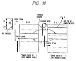
- the third scan and the fourth scan are performed, so that the printing is totally accomplished by two overwritings with half the density.
- This division feed overwriting can reduce the unevenness of density and the occurrence of overwrite streaks caused by the error of pitch feed.
- the print head 15 with a number of nozzles arranged integrally in one column may include an abnormal. nozzle 15' in part thereof. This abnormal nozzle 15' is discriminated prior to each main scan by the above detecting device.
- image data (a') corresponding to the abnormal nozzle is removed from the image data (a) and transferred to the image data (b). And at the second scan, such image data (a') is printed in the superposed state.
- the data (a') which may be printed abnormally or missed if none measure is taken can be correctly printed in accordance with the data.
- the abnormal nozzle 15' remains uncorrected, but is detected by making the trouble detection to be performed prior to the second scan (main scan), whereby the data (b') corresponding to such abnormal nozzle is likewise removed from image data (b) and transferred to the image data (a) to make the superposition.
- the data (a') and (b') are not left in the original image data so as not to be printed, but they should be removed therefrom. This is due to the fact that undischarge nozzle may be recovered capriciously, resulting in a risk that unexpected print may be conducted and the intended complement may be disordered.
- the missing/distortion of data with the abnormal nozzle can be complemented, because a print portion by the former half portion (leading print block A) of the recording head is again overprinted by the latter half portion (trailing print block B) of the recording head.
- image data of the leading print block A and image data of the trailing print block B are in a complemental relation to each other in which image data of one line is divided.
- the complement is performed if any abnormal nozzles occur in the leading print block A. It is to be noted that the trouble occurring in the trailing print block B is only reduced in respect of its degree of influence as described in U.S. Patent No. 4,963,882.
- An abnormal nozzle 15' in the trailing print block B is discriminated in the trouble detection prior to the main scan of printing. Because this abnormal nozzle will cause a trouble at the second scan to be performed next, a part of data (b') corresponding to this is cut out beforehand from data (b) and transferred to data (a), whereby the first scan is performed with this superimposed data.
- Fig. 12 shows an instance where the trouble disappears at the fourth scan.
- Data (b") corresponding to the abnormal nozzle in the trouble detection prior to the third scan has been already transferred to image data (a) and printed, with image data (b) containing blank, so that blank part is not printed at the fourth scan, but the printed image is not overlapped or missed.
- the complement can be performed wherever the abnormal nozzle occurs in the recording head.
- image data is divided into three pieces, whereby data corresponding to the trouble of two leading print blocks are respectively transferred to the next scan data, and data corresponding to the trouble of the trailing print block is transferred to the scan data of the first leading print block in such a manner as shown in Fig. 11.
- the multi-value print technique can be applied, so that the higher image quality of printed matter can be accomplished. Also, even if the number of overwritings may be increased for the purpose of higher image quality, the present invention allows for the discrimination for the condition of the recording head at high precision exactly in the same way by means of a dot state detecting device separately provided, with further remarkable effects obtained.
- the recording head is divided into three blocks, and two overprintings are performed with half of the density (or one-third the density from the viewpoint of the entire recording head), as heretofore described, using two leading print blocks A1, A2.
- the print data with the abnormal nozzle is sequentially stored in another image data area (c) for complemental print, and when the trailing print block B scans that portion, the data is sequentially read out and printed.
- This data area (c) is shown as one full screen for the easier explanation, but in practice it may be of minimum size.
- the trailing print block is concentrated on a role as the abnormal (undischarge) complemental block, bringing up the rear, whereby the full complement print can be fulfilled with a simple constitution.
- the detection of abnormal nozzle is performed by optically reading a print pattern, but may be performed along with the detection of disconnection occurring in the discharge heater (which checks for a resistor during the period between each discharge pulse applied in accordance with image data during the printing).
- the discrimination of abnormal nozzle is performed immediately before the printing, and such an abnormal nozzle, if any, is complemented, but any trouble occurring in mid course of printing (during the printing/scanning of a certain line) is not complemented.
- the heater disconnection detection is performed in unison, it is detected at which position of the line the trouble (undischarge) has occurred. Accordingly, the above examples-1 to -3 may be applied from that trouble occurring position of the line.
- Figs. 14A to 14D are diagrams for explaining the timing of disconnection detection, in which Fig. 14A shows the undischarge timing from the normal recording head, and for a recording head having a discharge frequency of 2.5 kHz, for example, the drive signal of recording head comes at every 400 ⁇ sec of T2.
- the drive time of heater 31 within the recording head is 10 ⁇ sec of T1.
- Fig. 14B is the timing for detecting the disconnection, in which quite short pulses as shown in Fig. 14C are issued during the period when discharge operation is not effected.
- Fig. 14C for a recording head having 256 nozzles, when pulses of 0.2 ⁇ sec are issued sequentially to each one of the nozzles at a frequency of 1 ⁇ sec, the consumption current of the recording head is detected by using a photocoupler 32 as shown in Fig. 15.
- the detection signal is ideally pulses as shown in Fig. 14C.
- the pulse width of several ⁇ sec is required at minimum, and the pulse width of about 0.2 ⁇ sec as in this example has no effects on the discharge.
- the detecting operation of disconnection will be described.
- the discharge heater 31 within the recording head is driven in accordance with the input pattern for detecting disconnection, and the consumption current at that time is detected by the photocoupler 32.
- the waveform for the output pattern is delayed by a slight amount from that of the input pattern because of the delay time period of a circuit system.
- the discriminating timings as indicated by the arrow, it is detected that the output is provided in accordance with the input pattern.
- the third output is not provided, whereby it is found that there is a disconnection.
- an input pattern is entered into a counter 33 to monitor the number of nozzle which is discriminating at present. If a discrimination of NG is made, the value of the counter at that time is latched, and a signal indicating the number of disconnected nozzle can be output to a CPU.
- control unit for controlling the whole recording apparatus.
- This control unit is composed of a CPU such as a microprocessor, a ROM for storing control programs or a variety of data, and a RAM for use as the work area of CPU.
- step S201 by issuing a start instruction (step S201), the system is actuated (step S202).
- step S203 the detection of abnormal nozzles is performed using the reading unit 11 at step S204.
- step S210 If there is no abnormal nozzle, the procedure transfers to step S210, where the printing with the recording head 7 is performed. On the other hand, if a trouble is detected, the procedure transfers to step S205, where the recovery operation is performed. Next, at step S206, the detection of abnormal nozzles is performed again, in which if no trouble is confirmed, the procedure transfers to step S210, where the printing is performed. On the other hand, if a trouble is confirmed, a check is made at step S207 to determine whether or not the nozzle having caused the trouble and the nozzle being subjected to the complement operation are overlapped. As a result, if overlapped, both the nozzles are abnormal and therefore can not be complemented, in which the procedure transfers to step S208, where a warning is issued and the operation of the recording apparatus is stopped.
- step S210 the data movement is performed with the above method at step S209, and then the procedure transfers to step S210, where the printing is performed. If the printing of that line is completed, a check is made at step S211 to determine whether or not that line is a last line. If it is a last line, the printing is terminated at step S213. If there remain some lines to be printed, the procedure transfers to step S212, where a check is made to determine whether or not the procedure is repeated predetermined times (e.g., five lines). If repeated predetermined times, the procedure returns to step S203, where the recovery operation is performed. On the other hand, if not repeated predetermined times, the procedure returns to step S204, where the detection operation of abnormal nozzles is executed. In the following, the same procedure is repeated.
- predetermined times e.g., five lines
- Figs. 17, 18 and 19 are diagrams for explaining the flow of image data.
- Fig. 17 is concerned with example-1 and example-2 (corresponding to Figs. 10A to 12), wherein the image data 301 is divided into odd number scan data 304 and even number scan data 305 by a data divider 302.
- a device for cutting out abnormal image data portion 306 is operated, wherein an abnormal image data portion 307 is transferred to the other scan data.
- the transferred data is superimposed by a data superimposing device 308, and transferred to a print head 309 for executing the printing.
- Fig. 18 is an explanation diagram in an extended version of three divisions and three superimpositions, wherein data is divided into the (3n+1)-th scan data 311, the (3n+2)-th scan data 312 and the (3n+3)-th scan data 313 (n is an integer more than or equal to zero), the abnromal image data portion 307 of leading print block being transferred respectively to the next scan data, but the abnormal image data portion 307 of trailing print block is transferred to the scan data prior to the corresponding scan.
- Fig. 19 is an explanation diagram for the example-3 (corresponding to Fig. 13), wherein the abnormal data 307 is stored in a complemental data area 310 and transferred therefrom to a complemental print block 309' of the print head 309 for executing the printing.
- the recording apparatus is not stopped even if an abnormal nozzle occurs, so that the span of life of the recording head is greatly extended.
- This technique is not only applicable to an ink jet recording apparatus using electricity-heat converters for discharging the ink through the nozzles, but also to an ink jet recording apparatus using electricity-heat converters such as piezo elements for discharging the ink through the nozzles, and a recording apparatus having a number of recording elements such as a thermal recording apparatus using a thermal transfer recording method and a thermosensible paper.
- Figs. 20 and 21 are diagrams showing a basic configuration of an ink jet recording apparatus for performing the printing on the cloths to which one embodiment of the present invention is applied.
- This ink jet recording apparatus is constituted as a system, principally consisting of an image reading device 401 for reading an original image created by a designer and converting the original image into original data represented by an electrical signal, an image processing unit 402 for processing original data from the image reading apparatus 401 to be output as image data, and an image recording unit 403 for recording onto the recording medium such as cloths on the basis of image data created by the image processing unit 402.
- the image reading device 401 reads original image with a CCD image sensor.
- the image processing unit 402 creates data of driving an ink jet recording unit A-2 (see Fig. 21) for discharging four color inks of magenta (code M), cyan (code C), yellow (code Y) and black (code Bk) as will be described later from input original data.
- the creation of data involves the image processing for reproducing original image in ink dots, the coloration for determining color tone, and the processing or selection of design size, such as alteration, enlargement or reduction of layout.
- the printing is performed by the ink jet recording unit A-2.
- Fig. 21 is a typical view showing schematically a preferred image recording unit for the recording apparatus for textile printing as above described.
- This recording apparatus is largely comprised of a cloths supply unit B for supplying the recording medium such as a roll of cloths pretreated for the textile printing, a main unit for performing the printing with an ink jet head by feeding accurately the recording medium supplied thereto, and a winding unit C for winding the printed recording medium after dried.
- the main unit A consists of a precision feeding unit A-1 for recording medium including a platen and an ink jet recording unit A-2.
- Pretreated roll-like recording medium 236 is delivered from the cloths supply unit B to the main unit A.
- a thin endless belt 237 which is precisely driven stepwise is looped around a drive roller 247 and a winding roller 249.
- the drive roller 247 is directly driven stepwise by a stepping motor (not shown) of high resolution to feed the belt stepwise by the amount of steps.
- Supplied cloth 236 is pressed on the surface of the belt 237 backed up by the winding roller 249 by a presser roller 240, and adhered thereto.
- the printed recording medium is peeled off to be dried. again through a post drying unit 246 which is similar to the heating plate 234 and the hot air duct 235 as previously described, and wound around a winding roll 248 while being guided by a guide roll 241. And such wound recording medium 236 is removed from the main apparatus, and subjected to the post-treatments. such as coloring,. cleaning, and drying in batch processing to provide the final product.
- the recording medium 236 is adhered onto the belt 237, and fed stepwise in the upper direction in the figure.
- the first print unit 231 provided downward in the figure is provided with a first carriage 244 having mounted thereon eight ink jet heads for Y, M, C, Bk and special colors S1 to S4.
- the ink jet head (recording head) in this embodiment has elements for generating the heat energy causing film boiling in the ink as the energy used to discharge the ink, and has 128 discharge orifices arranged with a density of 400 dpi (dots/inch).
- the air of lower humidity is applied to the drying recording medium 236 by blowing the dry hot air from a supply duct 230 provided downstream thereof, so that further effects are obtained. And the air containing sufficient moisture and flowing in the opposite direction to a conveying direction of the recording medium 236 is sucked in a much greater amount than a blowing amount from a suction duct 233 provided upstream thereof so as to prevent the evaporated water contents from bedewing surrounding mechanical components.
- a supply source of hot air is provided on the rear side as shown in Fig. 22, and the suction is performed on the fore side, so that the pressure difference between a blowout opening 238 and a suction opening 239 placed opposed to the recording medium 236 is rendered uniform over the entire area in a longitudinal direction.
- a second print unit 231' which is comprised of a second carriage 244' of the same constitution as the first carriage.
- the present invention is also applicable wherein the total length of recording element row is defined as a sum of the length for the head in the first print unit and the length for the head in the second print unit, for example, and with the head in the first print block as one block and the head in the second print block as the other block, image data involved with abnormal recording element is printed by the use of the recording element of the other block containing no abnormal recording elements.
- the recording medium After passing through an ink jet textile printing process, is subjected to drying (including the air drying). And subsequently the recording medium is subjected to a process in which the dye on recording medium fiber is diffused, and fixed thereto. With this process, sufficient coloration and fastness with the fixing of dye can be obtained.
- This diffusion and fixing process may be any one of conventionally well-known methods, such as for example, a steaming method. Note that before textile printing, the recording medium may be subjected to alkaline treatment.
- alkaline substance examples include alkaline metal hydroxide such as sodium hydroxide and potassium hydroxide, amines such as mono-, di-, or triethanolamine, and alkaline metal carbonate or bicarbonate such as sodium carbonate, potassium carbonate and sodium bicarbonate. Further, they include organic acid metallic salt such as calcium acetate and barium acetate, ammonia and ammonium compounds. Also, sodium trichloroacetate which becomes alkaline substance under the steaming and heating may be used. Particularly preferable alkaline substance may be sodium carbonate and sodium bicarbonate for use in coloring of reactive dye.
- alkaline metal hydroxide such as sodium hydroxide and potassium hydroxide
- amines such as mono-, di-, or triethanolamine
- alkaline metal carbonate or bicarbonate such as sodium carbonate, potassium carbonate and sodium bicarbonate.
- organic acid metallic salt such as calcium acetate and barium acetate, ammonia and ammonium compounds.
- sodium trichloroacetate which becomes al
- water soluble polymer examples include starch substances such as corn and wheat flour, cellulose substances such as carboxymethyl cellulose, methyl cellulose and hydroxyethyl cellulose, polysaccharides such as sodium alginate, gum arabic, locust beam gum, tragacanth gum, guar gum, and tamarind seeds, protein substances such as gelatine and casein, and natural water soluble substances such as tannium and lignin.
- examples of synthetic polymer include polyvinyl alcohol compounds, polyethylene oxide compounds, acrylic acid type water soluble polymer, and maleic anhydride type water soluble polymer. Among them, polysaccharide polymer and cellulose polymer are preferable.
- water soluble metallic salt examples include compounds having a pH of 4 to 10 and making typical ionic crystals such as halides of alkaline metal and alkaline earth metal.
- Typical examples of such compound include alkaline metals such as NaCl, Na 2 SO 4 , KCL and CH 3 COONa, and alkaline earth metals such as CaCl 2 and MgCl 2 .
- salts of Na, K and Ca are preferable.
- the method of pre-treating the cloths to contain any one of the above-cited substances is not specifically limited, but may be normally any one of dipping, pad, coating, and spray methods.
- the printed matter subjected to the post-treatment as above described is cut off in a desired size, cut pieces are subjected to a process for obtaining the final product such as suturing, bonding, or welding, to thereby provide a one-piece dress, a dress, a necktie, a swimsuit, an apron, a scarf, a quilt cover, a sofa cover, a handkerchief, a curtain, a book cover, room shoes, a tapestry, a tablecloth, and so on.
- Numerous methods of processing the cloths by suturing to provide clothes or other daily needs having been described in well-known publications, such as "Modern knitwear manual", published by Seni-journal, and monthly “Souen”, published by Bunka Shuppan.
- the present invention brings about excellent effects particularly in a recording head or a recording device of the ink jet system for recording by forming fine ink droplets with the heat energy among the various inkjet recording systems.
- the constitution of the recording head in addition to the combination of the discharging orifice, liquid channel, and electricity-heat converter (linear liquid channel or right-angled liquid channel) as disclosed in the above-mentioned respective specifications, the constitution by use of U.S. Patent 4,558,333 or 4,459,600 disclosing the constitution having the heat acting portion arranged in the flexed region is also included in the present invention.
- the present invention can be also effectively made the constitution as disclosed in Japanese Laid-Open Patent Application No. 59-123670 which discloses the constitution using a slit common to a plurality of electricity-heat converters as the discharging portion of the electricity-heat converter or Japanese Laid-Open Patent Application No. 59-138461 which discloses the constitution having the opening for absorbing pressure wave of heat energy correspondent to the discharging portion.
- the present invention is effective for a recording head of the freely exchangeable chip type which enables electrical connection to the main device or supply of ink from the main device by being mounted on the main device, or a recording head of the cartridge type having an ink tank integrally provided on the recording head itself.
- a restoration means for the recording head, a preliminary auxiliary means, etc., provided as the constitution of the recording device of the present invention is preferable, because the effect of the present invention can be further stabilized.
- Specific examples of these may include, for the recording head, capping means, cleaning means, pressurization or suction means, electricity-heat converters or another type of heating elements, or preliminary heating means according to a combination of these, and it is also effective for performing stable recording to perform preliminary mode which performs discharging separate from recording.
- the use of the ink having a property of liquefying only with the application of heat energy such as liquefying with the application of heat energy in accordance with a recording signal so that liquid ink is discharged, or may solidify prior to reaching a recording medium, is also applicable in the present invention.
- the ink may be held as liquid or solid in recesses or through holes of a porous sheet, which is placed opposed to electricity-heat converters, as described in Japanese Laid-Open Patent Application No. 54-56847 or No. 60-71260.
- the most effective method for the ink as above described in the present invention is based on the film boiling.
- a recording apparatus may be used in the form of a printer integrally or separately provided as the image output terminal for use in an information processing equipment such as a word processor or a computer, a copying machine in combination with a reader, or a facsimile terminal equipment having the transmission and reception feature.
- an information processing equipment such as a word processor or a computer, a copying machine in combination with a reader, or a facsimile terminal equipment having the transmission and reception feature.
- Fig. 23 is a block diagram showing a schematic configuration in which a recording apparatus of the present invention is applied to the information processing apparatus having the features of a word processor, a personal computer, a facsimile terminal equipment, a copying machine and an electronic typewriter.
- 501 is a control unit for controlling the whole apparatus, wherein it comprises a CPU such as a microprocessor or various I/O ports, and controls by outputting or inputting a control signal or data signal to or from each of sections, respectively.
- a display section which displays various kinds of menus, document information, and image data read by an image reader 507 on the display screen 503 is a transparent, pressure sensitive touch panel provided on the display section 502, which enables the entry of an item or coordinate value on the display section 502 by depressing its surface with a finger or the like.
- a printer section 506 is useful as the output terminal for a word processor, a personal computer, a facsimile terminal equipment, a copying machine, or an electronic typewriter, to which a recording apparatus according to the present invention is applied.
- 507 is an image reader section which reads original data photoelectrically, and is provided midway on the conveying path of original to read a facsimile or copying original, and other various types of original.
- 508 is a FAX receiving/transmitting section for FAX transmitting original data read by the image reader section 507 or for FAX receiving and decoding facsimile signals that are transmitted thereto, which has an interface facility with the outside.
- 509 is a telephone section comprising various telephone features, such as ordinary telephone or automatic answering telephone.
- 510 is a memory section comprising a ROM for storing system programs, manager programs and other application programs, character fonts, and dictionaries, a RAM for storing an application program loaded from the external storage device 512 and character information, and a video RAM.
- 511 is a keyboard section for inputting document information or various commands.
- 512 is the external storage device which is a storage medium consisting of floppy disk or hard disk, wherein this external storage device 512 is used to store character information, music or audio data, and user's application programs.
- Fig. 24 is an appearance view of the information processing apparatus as shown in Fig. 23.
- 601 is a flat panel display formed of a liquid crystal for displaying various kinds of menus, graphic data or document information.
- a touch panel On this display 601 is installed a touch panel, which enables the entry of coordinate or specified item by depressing the surface of the touch panel with a finger or the like.
- 602 is a handset to be used when the apparatus functions as a telephone.
- a keyboard 603 is detchably connected via a cord to the main device, and is used to input various character information or data.
- the keyboard 603 is also provided with various function keys 604.
- 605 is an opening for insertion of the floppy disk.
- a paper laying board for laying thereon a paper to be read by the image reader section 607, in which a read paper is exhausted from the rear side of device.
- received data is recorded by a printer 607.
- the display 601 may be a CRT, but is preferably a flat panel such as a liquid crystal display using a ferroelectric liquid crystal. This is because the display can be made more compact, thinner, and lighter.
- various information input from the keyboard 511 in Fig. 23 are processed according to a predetermined program by the control unit 501, and output to the printer 506 as the image.
- the facsimile information input from the FAX receiving/transmitting section 508 via the transmission line is received according to a predetermined program by the control section 501, and output to the printer section 506 as the received image.
- a recording apparatus according to the present invention is applied to the multifunctional information processing apparatus as above described, higher quality recording images can be obtained so that the features of the information processing apparatus can be further improved.
- image data to be given to abnormal recording element is moved to image data to be given to the other recording element, so that the recording can be complemented by the other recording element, whereby a non-defective desired image can be obtained.
Applications Claiming Priority (7)
| Application Number | Priority Date | Filing Date | Title |
|---|---|---|---|
| JP107679/92 | 1992-04-27 | ||
| JP10767992 | 1992-04-27 | ||
| JP10767992 | 1992-04-27 | ||
| JP5079582A JP3005136B2 (ja) | 1992-04-27 | 1993-04-06 | プリント装置およびプリント方法 |
| JP79582/93 | 1993-04-06 | ||
| JP7958293 | 1993-04-06 | ||
| EP93303185A EP0568283B1 (fr) | 1992-04-27 | 1993-04-23 | Dispositif et procédé d'enregistrement |
Related Parent Applications (1)
| Application Number | Title | Priority Date | Filing Date |
|---|---|---|---|
| EP93303185A Division EP0568283B1 (fr) | 1992-04-27 | 1993-04-23 | Dispositif et procédé d'enregistrement |
Publications (3)
| Publication Number | Publication Date |
|---|---|
| EP0918432A2 true EP0918432A2 (fr) | 1999-05-26 |
| EP0918432A3 EP0918432A3 (fr) | 1999-06-16 |
| EP0918432B1 EP0918432B1 (fr) | 2004-06-23 |
Family
ID=26420600
Family Applications (2)
| Application Number | Title | Priority Date | Filing Date |
|---|---|---|---|
| EP99200382A Expired - Lifetime EP0918432B1 (fr) | 1992-04-27 | 1993-04-23 | Dispositif et procédé d'enregistrement |
| EP93303185A Expired - Lifetime EP0568283B1 (fr) | 1992-04-27 | 1993-04-23 | Dispositif et procédé d'enregistrement |
Family Applications After (1)
| Application Number | Title | Priority Date | Filing Date |
|---|---|---|---|
| EP93303185A Expired - Lifetime EP0568283B1 (fr) | 1992-04-27 | 1993-04-23 | Dispositif et procédé d'enregistrement |
Country Status (8)
| Country | Link |
|---|---|
| US (2) | US6174039B1 (fr) |
| EP (2) | EP0918432B1 (fr) |
| JP (1) | JP3005136B2 (fr) |
| KR (1) | KR0137925B1 (fr) |
| CN (1) | CN1056952C (fr) |
| AT (2) | ATE188077T1 (fr) |
| DE (2) | DE69333561T2 (fr) |
| ES (1) | ES2142333T3 (fr) |
Cited By (2)
| Publication number | Priority date | Publication date | Assignee | Title |
|---|---|---|---|---|
| WO2003082587A1 (fr) * | 2002-03-29 | 2003-10-09 | Olympus Corporation | Diagramme d'essai, systeme et procede pour l'analyse de caracteristiques geometriques, imprimante, et imprimante a jet d'encre |
| EP1464387A2 (fr) * | 2003-04-02 | 2004-10-06 | Agilent Technologies, Inc. | Synthèse in situ de matrices d'acides nucléiques |
Families Citing this family (85)
| Publication number | Priority date | Publication date | Assignee | Title |
|---|---|---|---|---|
| US6036300A (en) * | 1992-02-26 | 2000-03-14 | Canon Kabushiki Kaisha | Method for recording image and apparatus therefor and recorded matter by such an apparatus |
| EP1343304B1 (fr) * | 1992-02-26 | 2012-05-09 | Canon Kabushiki Kaisha | Procédé pour enrégistrer des images, appareil pour ceci, et matériel enregistré par un tel appareil |
| JP3308717B2 (ja) | 1994-07-21 | 2002-07-29 | キヤノン株式会社 | 記録装置及び記録方法 |
| US5699168A (en) * | 1995-06-22 | 1997-12-16 | Texas Instruments Incorporated | Grayscale printing with sliding window memory |
| JP3359211B2 (ja) | 1995-12-28 | 2002-12-24 | キヤノン株式会社 | 記録方法および記録装置 |
| IL117278A (en) | 1996-02-27 | 2000-02-17 | Idanit Tech Ltd | Method for operating an ink jet printer |
| JPH106488A (ja) * | 1996-06-24 | 1998-01-13 | Canon Inc | インクジェット記録方法及びその装置 |
| US5751312A (en) * | 1996-09-04 | 1998-05-12 | Lexmark International, Inc. | Method of inhibiting a print artifact associated with a printer pause |
| US6283572B1 (en) † | 1997-03-04 | 2001-09-04 | Hewlett-Packard Company | Dynamic multi-pass print mode corrections to compensate for malfunctioning inkjet nozzles |
| US6010205A (en) * | 1997-03-12 | 2000-01-04 | Raster Graphics Inc. | Method and apparatus for improved printing |
| US6199969B1 (en) * | 1997-08-01 | 2001-03-13 | Encad, Inc. | Method and system for detecting nonfunctional elements in an ink jet printer |
| JP3174539B2 (ja) | 1997-09-08 | 2001-06-11 | キヤノン株式会社 | 記録方法および記録装置 |
| JP3368194B2 (ja) | 1997-12-24 | 2003-01-20 | キヤノン株式会社 | 記録装置 |
| JP4250264B2 (ja) | 1998-07-22 | 2009-04-08 | キヤノン株式会社 | 記録装置及びその制御方法、コンピュータ可読メモリ |
| JP2000052597A (ja) * | 1998-08-11 | 2000-02-22 | Casio Comput Co Ltd | 印字制御装置 |
| NL1010238C2 (nl) * | 1998-10-02 | 2000-04-04 | Oce Tech Bv | Beeldvormingsinrichting met afzonderlijk bekrachtigbare beeldvormingselementen. |
| EP1065057A4 (fr) | 1998-12-25 | 2001-04-18 | Seiko Epson Corp | Procede d'impression et appareil d'impression pour inspecter des points manquants, et support d'impression pour imprimer ce programme d'inspection |
| JP3900723B2 (ja) * | 1998-12-25 | 2007-04-04 | セイコーエプソン株式会社 | ドット抜け検査方法および印刷装置、並びに、そのためのプログラムを記録した記録媒体 |
| WO2000038927A1 (fr) * | 1998-12-25 | 2000-07-06 | Seiko Epson Corporation | Procede d'impression et appareil d'impression pour inspecter des points manquants, et support d'impression pour imprimer ce programme d'inspection |
| JP3485015B2 (ja) * | 1999-03-09 | 2004-01-13 | セイコーエプソン株式会社 | ドット抜け検査を行う双方向印刷 |
| EP1681165A3 (fr) * | 1999-03-10 | 2009-04-01 | Seiko Epson Corporation | Ajustement du déplacement de l'emplacement d'un point à l'aide d'informations selon lesquelles aucun point ne doit être formé pour chaque unité de pixel |
| JP2000263772A (ja) * | 1999-03-17 | 2000-09-26 | Seiko Epson Corp | ドット抜け検査を行う印刷方法および印刷装置、並びに、そのためのプログラムを記録した記録媒体 |
| AUPP996099A0 (en) | 1999-04-23 | 1999-05-20 | Silverbrook Research Pty Ltd | A method and apparatus(sprint01) |
| JP2001030510A (ja) * | 1999-07-19 | 2001-02-06 | Ricoh Co Ltd | インクジェット記録装置 |
| US6278469B1 (en) * | 1999-09-20 | 2001-08-21 | Hewlett-Packard Company | Customizing printmasks for printhead nozzle aberrations |
| US6347857B1 (en) * | 1999-09-23 | 2002-02-19 | Encad, Inc. | Ink droplet analysis apparatus |
| US6679601B1 (en) | 2000-05-30 | 2004-01-20 | Hewlett-Packard Development Company, L.P. | Dual-web transport belt cleaning apparatus and method |
| US6530658B1 (en) | 2000-05-30 | 2003-03-11 | Hewlett-Packard Company | Dispensing applicator and method of use |
| US6698878B1 (en) * | 2000-05-30 | 2004-03-02 | Hewlett-Packard Development Company, L.P. | Cleaning medium for ink-jet hard copy apparatus |
| DE10045168B4 (de) * | 2000-09-13 | 2008-07-31 | Hell Gravure Systems Gmbh & Co. Kg | Mehrstrahl-Belichtungsverfahren |
| US6764156B2 (en) * | 2000-12-12 | 2004-07-20 | Xerox Corporation | Head signature correction in a high resolution printer |
| US7731905B2 (en) | 2001-03-26 | 2010-06-08 | Canon Kabushiki Kaisha | Process for producing probe carrier and apparatus thereof |
| JP4522012B2 (ja) * | 2001-03-26 | 2010-08-11 | キヤノン株式会社 | プローブ担体の製造装置および製造方法 |
| JP4545974B2 (ja) * | 2001-03-26 | 2010-09-15 | キヤノン株式会社 | プローブ担体の製造方法及びその装置 |
| US6533380B1 (en) * | 2001-09-12 | 2003-03-18 | Xerox Corporation | Method and apparatus for reducing neighbor cross-talk and increasing robustness of an acoustic printing system against isolated ejector failure |
| JP4027204B2 (ja) | 2001-11-06 | 2007-12-26 | キヤノン株式会社 | 記録装置及び記録方法並びにデータ処理装置 |
| US7101011B2 (en) | 2001-11-06 | 2006-09-05 | Canon Kabushiki Kaisha | Recording apparatus, method and program utilizing compensation dots |
| JP2003136764A (ja) * | 2001-11-06 | 2003-05-14 | Canon Inc | インクジェット記録装置における画像補正方法 |
| US7201462B2 (en) | 2002-07-24 | 2007-04-10 | Canon Kabushiki Kaisha | Ink jet printing apparatus and method for correcting ejection driving |
| JP3870133B2 (ja) * | 2002-07-24 | 2007-01-17 | キヤノン株式会社 | インクジェット記録装置、およびインクジェット記録方法 |
| AU2003900180A0 (en) * | 2003-01-16 | 2003-01-30 | Silverbrook Research Pty Ltd | Method and apparatus (dam001) |
| EP1473662B1 (fr) * | 2003-04-30 | 2009-08-26 | Hewlett-Packard Development Company, L.P. | Appareil et procédé d'impression |
| JP4574141B2 (ja) * | 2003-08-29 | 2010-11-04 | キヤノン株式会社 | プリント装置および調整方法 |
| JP4262165B2 (ja) | 2003-09-03 | 2009-05-13 | キヤノン株式会社 | 記録装置及びデータ処理方法 |
| JP4227489B2 (ja) | 2003-09-03 | 2009-02-18 | キヤノン株式会社 | 記録装置及び記録方法 |
| JP4401715B2 (ja) * | 2003-09-05 | 2010-01-20 | キヤノン株式会社 | 記録位置調整方法、記録装置及び記録システム |
| JP2005161838A (ja) * | 2003-11-10 | 2005-06-23 | Seiko Epson Corp | 液滴吐出方法、液滴吐出装置、ノズル異常判定方法、表示装置、および電子機器 |
| US7152456B2 (en) * | 2004-01-14 | 2006-12-26 | Romer Incorporated | Automated robotic measuring system |
| CN100575112C (zh) * | 2004-06-25 | 2009-12-30 | 山特维克创新公司 | 具有高分辨率图像的软织物书及其制造方法 |
| JP4670291B2 (ja) * | 2004-09-21 | 2011-04-13 | 富士ゼロックス株式会社 | インクジェット記録ヘッド故障予測システム |
| JP4029895B2 (ja) | 2004-12-08 | 2008-01-09 | セイコーエプソン株式会社 | 液滴吐出装置、液滴吐出方法、電気光学装置の製造方法、電気光学装置および電子機器 |
| CN100443301C (zh) * | 2004-12-08 | 2008-12-17 | 精工爱普生株式会社 | 液滴喷出装置及喷出方法、电光学装置及其制造方法 |
| KR100750161B1 (ko) * | 2006-02-02 | 2007-08-17 | 삼성전자주식회사 | 잉크젯 화상형성장치의 결함 노즐 보상 방법 및 장치 |
| JP2007290361A (ja) | 2006-03-31 | 2007-11-08 | Canon Inc | 液体吐出ヘッド及びそれを用いた液体吐出装置 |
| JP4953703B2 (ja) | 2006-06-19 | 2012-06-13 | キヤノン株式会社 | 記録装置及びインク吐出不良検出方法 |
| JP2008000914A (ja) | 2006-06-20 | 2008-01-10 | Canon Inc | インクジェット記録装置、および、吐出状態検知方法 |
| KR101098595B1 (ko) * | 2006-10-09 | 2011-12-23 | 실버브룩 리서치 피티와이 리미티드 | 개방 액츄에이터 테스트를 갖는 프린트헤드 ic |
| JP4946515B2 (ja) * | 2007-03-01 | 2012-06-06 | 富士ゼロックス株式会社 | 印刷制御装置、印刷制御プログラム、印刷システム及び記録媒体 |
| JP5081339B2 (ja) * | 2007-03-19 | 2012-11-28 | 株式会社リコー | 画像形成装置 |
| US7448719B1 (en) * | 2007-05-11 | 2008-11-11 | Xerox Corporation | Ink jet printhead having a movable redundant array of nozzles |
| JP4442674B2 (ja) * | 2007-09-26 | 2010-03-31 | 富士ゼロックス株式会社 | 印刷制御装置 |
| JP5078529B2 (ja) | 2007-09-28 | 2012-11-21 | キヤノン株式会社 | インクジェット記録ヘッドおよびそれを備えるインクジェット記録装置 |
| JP5171353B2 (ja) * | 2008-03-31 | 2013-03-27 | セーレン株式会社 | インクジェット記録装置及びその吐出回復処理方法 |
| JP2010000699A (ja) * | 2008-06-20 | 2010-01-07 | Canon Inc | インクジェット記録装置 |
| JP5404022B2 (ja) | 2008-12-18 | 2014-01-29 | キヤノン株式会社 | 吐出状態判定方法 |
| WO2011054815A1 (fr) * | 2009-11-06 | 2011-05-12 | Oce-Technologies B.V. | Procédé d'étalonnage d'un réseau d'éléments d'imagerie |
| US8251476B2 (en) | 2010-02-03 | 2012-08-28 | Xerox Corporation | Ink drop position correction in the process direction based on ink drop position history |
| US8262190B2 (en) | 2010-05-14 | 2012-09-11 | Xerox Corporation | Method and system for measuring and compensating for process direction artifacts in an optical imaging system in an inkjet printer |
| US8721026B2 (en) | 2010-05-17 | 2014-05-13 | Xerox Corporation | Method for identifying and verifying dash structures as candidates for test patterns and replacement patterns in an inkjet printer |
| US8814316B2 (en) * | 2011-01-31 | 2014-08-26 | Canon Kabushiki Kaisha | Inkjet printing apparatus with defective nozzle detection |
| US8733876B2 (en) | 2011-11-29 | 2014-05-27 | Canon Kabushiki Kaisha | Printing apparatus |
| US8845064B2 (en) | 2011-11-29 | 2014-09-30 | Canon Kabushiki Kaisha | Printing apparatus |
| JP5949083B2 (ja) * | 2012-04-19 | 2016-07-06 | セイコーエプソン株式会社 | 画像記録装置、記録媒体搬送制御方法 |
| US9278552B2 (en) | 2012-06-06 | 2016-03-08 | Canon Kabushiki Kaisha | Ink jet printing apparatus and control method thereof |
| US9211699B2 (en) * | 2012-07-10 | 2015-12-15 | Hewlett-Packard Development Company, L.P. | Method of controlling a printer and printer having at least one print bar |
| US8840223B2 (en) | 2012-11-19 | 2014-09-23 | Xerox Corporation | Compensation for alignment errors in an optical sensor |
| US8764149B1 (en) * | 2013-01-17 | 2014-07-01 | Xerox Corporation | System and method for process direction registration of inkjets in a printer operating with a high speed image receiving surface |
| CN104417064B (zh) | 2013-09-03 | 2016-09-07 | 北大方正集团有限公司 | 一种喷墨打印机喷嘴的检测方法及装置 |
| JP6883380B2 (ja) * | 2015-08-27 | 2021-06-09 | セイコーエプソン株式会社 | 液体噴射装置、制御装置、記録システム及びプログラム |
| JP6676312B2 (ja) * | 2015-08-27 | 2020-04-08 | キヤノン株式会社 | 印刷装置、印刷装置の制御方法、及びプログラム |
| JP6855400B2 (ja) * | 2018-01-31 | 2021-04-07 | キヤノン株式会社 | 記録装置および制御方法 |
| CN110202936B (zh) * | 2018-02-28 | 2020-12-08 | 森大(深圳)技术有限公司 | 基于状态图检测喷嘴是否异常的方法、装置、设备及介质 |
| JP7415445B2 (ja) | 2019-10-31 | 2024-01-17 | セイコーエプソン株式会社 | 液体吐出装置 |
| JP7244806B2 (ja) * | 2021-03-16 | 2023-03-23 | セイコーエプソン株式会社 | 液体噴射装置 |
| CN114475036B (zh) * | 2022-02-17 | 2023-03-03 | 北京航空航天大学 | 一种基于液滴沸腾的提高喷墨打印质量的方法 |
Citations (4)
| Publication number | Priority date | Publication date | Assignee | Title |
|---|---|---|---|---|
| EP0046118A2 (fr) * | 1980-08-13 | 1982-02-17 | Matra | Procédé et dispositif d'analyse et/ou de restitution de documents |
| JPS60201965A (ja) * | 1984-03-26 | 1985-10-12 | Nec Corp | ドツト抜け補償プリンタ |
| JPH02192957A (ja) * | 1989-01-20 | 1990-07-30 | Nec Corp | ドットインパクトシリアルプリンタ |
| EP0443832A1 (fr) * | 1990-02-23 | 1991-08-28 | Canon Kabushiki Kaisha | Appareil de transmission d'image |
Family Cites Families (28)
| Publication number | Priority date | Publication date | Assignee | Title |
|---|---|---|---|---|
| CA1127227A (fr) | 1977-10-03 | 1982-07-06 | Ichiro Endo | Procede d'enregistrement a jet liquide et appareil d'enregistrement |
| JPS5936879B2 (ja) | 1977-10-14 | 1984-09-06 | キヤノン株式会社 | 熱転写記録用媒体 |
| US4330787A (en) | 1978-10-31 | 1982-05-18 | Canon Kabushiki Kaisha | Liquid jet recording device |
| US4345262A (en) | 1979-02-19 | 1982-08-17 | Canon Kabushiki Kaisha | Ink jet recording method |
| US4463359A (en) | 1979-04-02 | 1984-07-31 | Canon Kabushiki Kaisha | Droplet generating method and apparatus thereof |
| US4313124A (en) | 1979-05-18 | 1982-01-26 | Canon Kabushiki Kaisha | Liquid jet recording process and liquid jet recording head |
| US4436439A (en) * | 1980-08-27 | 1984-03-13 | Epson Corporation | Small printer |
| US4558333A (en) | 1981-07-09 | 1985-12-10 | Canon Kabushiki Kaisha | Liquid jet recording head |
| JPS59123670A (ja) | 1982-12-28 | 1984-07-17 | Canon Inc | インクジエツトヘツド |
| JPS59138461A (ja) | 1983-01-28 | 1984-08-08 | Canon Inc | 液体噴射記録装置 |
| JPS6071260A (ja) | 1983-09-28 | 1985-04-23 | Erumu:Kk | 記録装置 |
| JPS60104335A (ja) * | 1983-11-10 | 1985-06-08 | Canon Inc | インクジエツト記録装置 |
| JPS61123545A (ja) | 1984-11-21 | 1986-06-11 | Konishiroku Photo Ind Co Ltd | プリンタ |
| US4725849A (en) * | 1985-08-29 | 1988-02-16 | Canon Kabushiki Kaisha | Process for cloth printing by ink-jet system |
| JPS6253492A (ja) | 1985-08-29 | 1987-03-09 | キヤノン株式会社 | 捺染方法 |
| JPH01310965A (ja) * | 1988-06-10 | 1989-12-15 | Canon Inc | 画像記録装置 |
| JPH0253976A (ja) * | 1988-08-11 | 1990-02-22 | Seiren Co Ltd | 布はくの染色方法 |
| JP2787449B2 (ja) | 1988-08-31 | 1998-08-20 | セーレン株式会社 | 染色方法 |
| JP2731003B2 (ja) * | 1988-12-06 | 1998-03-25 | キヤノン株式会社 | 液体噴射記録装置 |
| US4963882B1 (en) | 1988-12-27 | 1996-10-29 | Hewlett Packard Co | Printing of pixel locations by an ink jet printer using multiple nozzles for each pixel or pixel row |
| JP3104133B2 (ja) * | 1989-06-27 | 2000-10-30 | セーレン株式会社 | カラーカードの作成方法 |
| JPH0346589A (ja) | 1989-07-13 | 1991-02-27 | Mitsubishi Electric Corp | 測距装置 |
| US4967203A (en) | 1989-09-29 | 1990-10-30 | Hewlett-Packard Company | Interlace printing process |
| US5121131A (en) * | 1989-10-30 | 1992-06-09 | Drexler Technology Corporation | Instant high contrast imaging system |
| JPH03245667A (ja) * | 1990-02-23 | 1991-11-01 | Canon Inc | ファクシミリ装置 |
| US5124720A (en) * | 1990-08-01 | 1992-06-23 | Hewlett-Packard Company | Fault-tolerant dot-matrix printing |
| EP0817113B1 (fr) | 1991-08-02 | 2003-09-24 | Canon Kabushiki Kaisha | Méthode d'enregistrement à jet d'encre |
| US6036300A (en) | 1992-02-26 | 2000-03-14 | Canon Kabushiki Kaisha | Method for recording image and apparatus therefor and recorded matter by such an apparatus |
-
1993
- 1993-04-06 JP JP5079582A patent/JP3005136B2/ja not_active Expired - Fee Related
- 1993-04-23 ES ES93303185T patent/ES2142333T3/es not_active Expired - Lifetime
- 1993-04-23 AT AT93303185T patent/ATE188077T1/de active
- 1993-04-23 DE DE69333561T patent/DE69333561T2/de not_active Expired - Lifetime
- 1993-04-23 EP EP99200382A patent/EP0918432B1/fr not_active Expired - Lifetime
- 1993-04-23 DE DE69327360T patent/DE69327360T2/de not_active Expired - Lifetime
- 1993-04-23 AT AT99200382T patent/ATE270018T1/de not_active IP Right Cessation
- 1993-04-23 EP EP93303185A patent/EP0568283B1/fr not_active Expired - Lifetime
- 1993-04-27 KR KR1019930007057A patent/KR0137925B1/ko not_active IP Right Cessation
- 1993-04-27 CN CN93106132A patent/CN1056952C/zh not_active Expired - Fee Related
-
1996
- 1996-12-27 US US08/774,891 patent/US6174039B1/en not_active Expired - Lifetime
-
1999
- 1999-03-24 US US09/275,445 patent/US6168261B1/en not_active Expired - Lifetime
Patent Citations (4)
| Publication number | Priority date | Publication date | Assignee | Title |
|---|---|---|---|---|
| EP0046118A2 (fr) * | 1980-08-13 | 1982-02-17 | Matra | Procédé et dispositif d'analyse et/ou de restitution de documents |
| JPS60201965A (ja) * | 1984-03-26 | 1985-10-12 | Nec Corp | ドツト抜け補償プリンタ |
| JPH02192957A (ja) * | 1989-01-20 | 1990-07-30 | Nec Corp | ドットインパクトシリアルプリンタ |
| EP0443832A1 (fr) * | 1990-02-23 | 1991-08-28 | Canon Kabushiki Kaisha | Appareil de transmission d'image |
Non-Patent Citations (2)
| Title |
|---|
| PATENT ABSTRACTS OF JAPAN vol. 010, no. 051 (M-457), 28 February 1986 & JP 60 201965 A (NIPPON DENKI KK), 12 October 1985 * |
| PATENT ABSTRACTS OF JAPAN vol. 014, no. 478 (M-1036), 18 October 1990 & JP 02 192957 A (NEC CORP), 30 July 1990 * |
Cited By (5)
| Publication number | Priority date | Publication date | Assignee | Title |
|---|---|---|---|---|
| WO2003082587A1 (fr) * | 2002-03-29 | 2003-10-09 | Olympus Corporation | Diagramme d'essai, systeme et procede pour l'analyse de caracteristiques geometriques, imprimante, et imprimante a jet d'encre |
| US7419230B2 (en) | 2002-03-29 | 2008-09-02 | Olympus Corporation | Test chart geometrical characteristic analysis system geometrical characteristic analysis method printer and ink-jet printer |
| EP1464387A2 (fr) * | 2003-04-02 | 2004-10-06 | Agilent Technologies, Inc. | Synthèse in situ de matrices d'acides nucléiques |
| EP1464387A3 (fr) * | 2003-04-02 | 2005-06-22 | Agilent Technologies, Inc. | Synthèse in situ de matrices d'acides nucléiques |
| US7534561B2 (en) | 2003-04-02 | 2009-05-19 | Agilent Technologies, Inc. | Nucleic acid array in situ fabrication methods and arrays produced using the same |
Also Published As
| Publication number | Publication date |
|---|---|
| EP0918432A3 (fr) | 1999-06-16 |
| ES2142333T3 (es) | 2000-04-16 |
| EP0918432B1 (fr) | 2004-06-23 |
| KR0137925B1 (ko) | 1998-05-15 |
| CN1089551A (zh) | 1994-07-20 |
| CN1056952C (zh) | 2000-09-27 |
| DE69333561D1 (de) | 2004-07-29 |
| US6168261B1 (en) | 2001-01-02 |
| ATE188077T1 (de) | 2000-01-15 |
| US6174039B1 (en) | 2001-01-16 |
| ATE270018T1 (de) | 2004-07-15 |
| JPH0679956A (ja) | 1994-03-22 |
| DE69333561T2 (de) | 2005-08-18 |
| JP3005136B2 (ja) | 2000-01-31 |
| KR940005403A (ko) | 1994-03-21 |
| EP0568283B1 (fr) | 1999-12-22 |
| DE69327360D1 (de) | 2000-01-27 |
| EP0568283A1 (fr) | 1993-11-03 |
| DE69327360T2 (de) | 2000-05-11 |
Similar Documents
| Publication | Publication Date | Title |
|---|---|---|
| EP0918432B1 (fr) | Dispositif et procédé d'enregistrement | |
| US6547361B1 (en) | Image recording apparatus which compensates for a defective recording area | |
| US5966145A (en) | Ink jet printing on the full width of a printing medium | |
| JP2672767B2 (ja) | プリント方法及び装置及びそのプリント物及び加工品 | |
| EP0613288B1 (fr) | Dispositif de traitement d'images, dispositif de formation d'images, et méthode de traitement d'images | |
| AU677196B2 (en) | Apparatus and method for manufacturing ink jet printed products and ink jet products manufactured using the method | |
| EP0633136B1 (fr) | Méthode et appareil d'impression par jet d'encre | |
| JP2711081B2 (ja) | インクジェットプリント装置、インクジェットプリント方法およびプリント物 | |
| EP0566540B1 (fr) | Appareil d'enregistrement et méthode pour la réalisation d'un produit avec cet appareil | |
| EP0796740B1 (fr) | Appareil et méthode d'enregistrement à jet d'encre et matière enregistrée | |
| EP0645245B1 (fr) | Dispositif de sortie d'images et système de formation d'images pour la correction de l'inégalité de densité | |
| JPH0825700A (ja) | 記録装置及び記録方法 | |
| US5877797A (en) | Ink-jet printing apparatus and method for printing on mixed fiber textiles | |
| JP3278218B2 (ja) | インクジェット記録装置及びインクジェット記録物の製法 | |
| JPH05309874A (ja) | 画像記録方法及び装置及びその記録物及び加工品 | |
| JPH07276673A (ja) | インクジェット記録装置、および該装置における色味調整方法 | |
| JP3245123B2 (ja) | プリント装置、該プリント装置を備えた画像形成装置、前記プリント装置を備えた情報処理装置、およびプリント方法 | |
| EP1343304B1 (fr) | Procédé pour enrégistrer des images, appareil pour ceci, et matériel enregistré par un tel appareil | |
| JP2019181893A (ja) | インクジェット記録装置及び記録方法 | |
| JP2001260339A (ja) | プリント装置 | |
| JP3159836B2 (ja) | インクジェットプリント装置及びインクジェットプリント方法 | |
| JP3029516B2 (ja) | インクジェット記録装置 | |
| JPH06328811A (ja) | インクジェットプリント装置、インクジェットプリント方法およびプリント物 |
Legal Events
| Date | Code | Title | Description |
|---|---|---|---|
| PUAI | Public reference made under article 153(3) epc to a published international application that has entered the european phase |
Free format text: ORIGINAL CODE: 0009012 |
|
| PUAL | Search report despatched |
Free format text: ORIGINAL CODE: 0009013 |
|
| AC | Divisional application: reference to earlier application |
Ref document number: 568283 Country of ref document: EP |
|
| AK | Designated contracting states |
Kind code of ref document: A2 Designated state(s): AT BE CH DE DK ES FR GB GR IE IT LI LU NL PT SE |
|
| AK | Designated contracting states |
Kind code of ref document: A3 Designated state(s): AT BE CH DE DK ES FR GB GR IE IT LI LU NL PT SE |
|
| RIC1 | Information provided on ipc code assigned before grant |
Free format text: 6H 04N 1/191 A, 6G 06K 15/00 B |
|
| 17P | Request for examination filed |
Effective date: 19991109 |
|
| 17Q | First examination report despatched |
Effective date: 20020902 |
|
| GRAP | Despatch of communication of intention to grant a patent |
Free format text: ORIGINAL CODE: EPIDOSNIGR1 |
|
| GRAS | Grant fee paid |
Free format text: ORIGINAL CODE: EPIDOSNIGR3 |
|
| GRAA | (expected) grant |
Free format text: ORIGINAL CODE: 0009210 |
|
| AC | Divisional application: reference to earlier application |
Ref document number: 0568283 Country of ref document: EP Kind code of ref document: P |
|
| AK | Designated contracting states |
Kind code of ref document: B1 Designated state(s): AT BE CH DE DK ES FR GB GR IE IT LI LU NL PT SE |
|
| PG25 | Lapsed in a contracting state [announced via postgrant information from national office to epo] |
Ref country code: NL Free format text: LAPSE BECAUSE OF FAILURE TO SUBMIT A TRANSLATION OF THE DESCRIPTION OR TO PAY THE FEE WITHIN THE PRESCRIBED TIME-LIMIT Effective date: 20040623 Ref country code: LI Free format text: LAPSE BECAUSE OF FAILURE TO SUBMIT A TRANSLATION OF THE DESCRIPTION OR TO PAY THE FEE WITHIN THE PRESCRIBED TIME-LIMIT Effective date: 20040623 Ref country code: IT Free format text: LAPSE BECAUSE OF FAILURE TO SUBMIT A TRANSLATION OF THE DESCRIPTION OR TO PAY THE FEE WITHIN THE PRESCRIBED TIME-LIMIT;WARNING: LAPSES OF ITALIAN PATENTS WITH EFFECTIVE DATE BEFORE 2007 MAY HAVE OCCURRED AT ANY TIME BEFORE 2007. THE CORRECT EFFECTIVE DATE MAY BE DIFFERENT FROM THE ONE RECORDED. Effective date: 20040623 Ref country code: FR Free format text: LAPSE BECAUSE OF FAILURE TO SUBMIT A TRANSLATION OF THE DESCRIPTION OR TO PAY THE FEE WITHIN THE PRESCRIBED TIME-LIMIT Effective date: 20040623 Ref country code: CH Free format text: LAPSE BECAUSE OF FAILURE TO SUBMIT A TRANSLATION OF THE DESCRIPTION OR TO PAY THE FEE WITHIN THE PRESCRIBED TIME-LIMIT Effective date: 20040623 Ref country code: BE Free format text: LAPSE BECAUSE OF FAILURE TO SUBMIT A TRANSLATION OF THE DESCRIPTION OR TO PAY THE FEE WITHIN THE PRESCRIBED TIME-LIMIT Effective date: 20040623 Ref country code: AT Free format text: LAPSE BECAUSE OF FAILURE TO SUBMIT A TRANSLATION OF THE DESCRIPTION OR TO PAY THE FEE WITHIN THE PRESCRIBED TIME-LIMIT Effective date: 20040623 |
|
| REG | Reference to a national code |
Ref country code: GB Ref legal event code: FG4D |
|
| REG | Reference to a national code |
Ref country code: CH Ref legal event code: EP |
|
| REG | Reference to a national code |
Ref country code: IE Ref legal event code: FG4D |
|
| REF | Corresponds to: |
Ref document number: 69333561 Country of ref document: DE Date of ref document: 20040729 Kind code of ref document: P |
|
| PG25 | Lapsed in a contracting state [announced via postgrant information from national office to epo] |
Ref country code: SE Free format text: LAPSE BECAUSE OF FAILURE TO SUBMIT A TRANSLATION OF THE DESCRIPTION OR TO PAY THE FEE WITHIN THE PRESCRIBED TIME-LIMIT Effective date: 20040923 Ref country code: GR Free format text: LAPSE BECAUSE OF FAILURE TO SUBMIT A TRANSLATION OF THE DESCRIPTION OR TO PAY THE FEE WITHIN THE PRESCRIBED TIME-LIMIT Effective date: 20040923 Ref country code: DK Free format text: LAPSE BECAUSE OF FAILURE TO SUBMIT A TRANSLATION OF THE DESCRIPTION OR TO PAY THE FEE WITHIN THE PRESCRIBED TIME-LIMIT Effective date: 20040923 |
|
| PG25 | Lapsed in a contracting state [announced via postgrant information from national office to epo] |
Ref country code: ES Free format text: LAPSE BECAUSE OF FAILURE TO SUBMIT A TRANSLATION OF THE DESCRIPTION OR TO PAY THE FEE WITHIN THE PRESCRIBED TIME-LIMIT Effective date: 20041004 |
|
| NLV1 | Nl: lapsed or annulled due to failure to fulfill the requirements of art. 29p and 29m of the patents act | ||
| REG | Reference to a national code |
Ref country code: CH Ref legal event code: PL |
|
| PG25 | Lapsed in a contracting state [announced via postgrant information from national office to epo] |
Ref country code: LU Free format text: LAPSE BECAUSE OF NON-PAYMENT OF DUE FEES Effective date: 20050423 |
|
| PG25 | Lapsed in a contracting state [announced via postgrant information from national office to epo] |
Ref country code: IE Free format text: LAPSE BECAUSE OF NON-PAYMENT OF DUE FEES Effective date: 20050425 |
|
| PLBE | No opposition filed within time limit |
Free format text: ORIGINAL CODE: 0009261 |
|
| STAA | Information on the status of an ep patent application or granted ep patent |
Free format text: STATUS: NO OPPOSITION FILED WITHIN TIME LIMIT |
|
| 26N | No opposition filed |
Effective date: 20050324 |
|
| EN | Fr: translation not filed | ||
| PG25 | Lapsed in a contracting state [announced via postgrant information from national office to epo] |
Ref country code: PT Free format text: LAPSE BECAUSE OF NON-PAYMENT OF DUE FEES Effective date: 20041123 |
|
| PGFP | Annual fee paid to national office [announced via postgrant information from national office to epo] |
Ref country code: DE Payment date: 20110430 Year of fee payment: 19 |
|
| PGFP | Annual fee paid to national office [announced via postgrant information from national office to epo] |
Ref country code: GB Payment date: 20110413 Year of fee payment: 19 |
|
| GBPC | Gb: european patent ceased through non-payment of renewal fee |
Effective date: 20120423 |
|
| PG25 | Lapsed in a contracting state [announced via postgrant information from national office to epo] |
Ref country code: GB Free format text: LAPSE BECAUSE OF NON-PAYMENT OF DUE FEES Effective date: 20120423 |
|
| REG | Reference to a national code |
Ref country code: DE Ref legal event code: R119 Ref document number: 69333561 Country of ref document: DE Effective date: 20121101 |
|
| PG25 | Lapsed in a contracting state [announced via postgrant information from national office to epo] |
Ref country code: DE Free format text: LAPSE BECAUSE OF NON-PAYMENT OF DUE FEES Effective date: 20121101 |