EP0443832A1 - Appareil de transmission d'image - Google Patents
Appareil de transmission d'image Download PDFInfo
- Publication number
- EP0443832A1 EP0443832A1 EP91301340A EP91301340A EP0443832A1 EP 0443832 A1 EP0443832 A1 EP 0443832A1 EP 91301340 A EP91301340 A EP 91301340A EP 91301340 A EP91301340 A EP 91301340A EP 0443832 A1 EP0443832 A1 EP 0443832A1
- Authority
- EP
- European Patent Office
- Prior art keywords
- ink
- discharge
- recording head
- recording
- image
- Prior art date
- Legal status (The legal status is an assumption and is not a legal conclusion. Google has not performed a legal analysis and makes no representation as to the accuracy of the status listed.)
- Granted
Links
- 238000011084 recovery Methods 0.000 claims abstract description 49
- 238000004891 communication Methods 0.000 claims abstract description 37
- 238000000034 method Methods 0.000 claims abstract description 16
- 230000004044 response Effects 0.000 claims abstract description 16
- 230000008569 process Effects 0.000 claims abstract description 10
- 238000001514 detection method Methods 0.000 claims description 43
- 238000007599 discharging Methods 0.000 claims description 18
- 230000008859 change Effects 0.000 claims description 15
- 230000000694 effects Effects 0.000 claims description 13
- 239000007788 liquid Substances 0.000 claims description 8
- 238000009835 boiling Methods 0.000 claims description 6
- 239000000463 material Substances 0.000 claims description 6
- 230000015572 biosynthetic process Effects 0.000 claims description 5
- 239000012528 membrane Substances 0.000 claims description 5
- 239000000976 ink Substances 0.000 description 245
- 238000007639 printing Methods 0.000 description 19
- 238000010586 diagram Methods 0.000 description 9
- 230000007246 mechanism Effects 0.000 description 7
- 230000005540 biological transmission Effects 0.000 description 5
- 238000005259 measurement Methods 0.000 description 5
- 230000008901 benefit Effects 0.000 description 4
- 230000006870 function Effects 0.000 description 4
- 238000010438 heat treatment Methods 0.000 description 4
- 238000001454 recorded image Methods 0.000 description 4
- 230000009471 action Effects 0.000 description 3
- 238000004140 cleaning Methods 0.000 description 2
- 239000003086 colorant Substances 0.000 description 2
- 230000008602 contraction Effects 0.000 description 2
- 230000001976 improved effect Effects 0.000 description 2
- 230000001939 inductive effect Effects 0.000 description 2
- 238000007689 inspection Methods 0.000 description 2
- 230000008093 supporting effect Effects 0.000 description 2
- 239000004695 Polyether sulfone Substances 0.000 description 1
- 239000004721 Polyphenylene oxide Substances 0.000 description 1
- 239000004743 Polypropylene Substances 0.000 description 1
- 230000002745 absorbent Effects 0.000 description 1
- 239000002250 absorbent Substances 0.000 description 1
- 230000008021 deposition Effects 0.000 description 1
- 230000002542 deteriorative effect Effects 0.000 description 1
- 238000003384 imaging method Methods 0.000 description 1
- 230000000977 initiatory effect Effects 0.000 description 1
- 239000004973 liquid crystal related substance Substances 0.000 description 1
- 238000012986 modification Methods 0.000 description 1
- 230000004048 modification Effects 0.000 description 1
- 229920002492 poly(sulfone) Polymers 0.000 description 1
- 229920006393 polyether sulfone Polymers 0.000 description 1
- 229920006380 polyphenylene oxide Polymers 0.000 description 1
- -1 polypropylene Polymers 0.000 description 1
- 229920001155 polypropylene Polymers 0.000 description 1
- 238000012545 processing Methods 0.000 description 1
- 230000002035 prolonged effect Effects 0.000 description 1
- 230000001681 protective effect Effects 0.000 description 1
- 239000012260 resinous material Substances 0.000 description 1
- 229920002379 silicone rubber Polymers 0.000 description 1
- 239000004945 silicone rubber Substances 0.000 description 1
- 238000011144 upstream manufacturing Methods 0.000 description 1
- 230000000007 visual effect Effects 0.000 description 1
- 238000004804 winding Methods 0.000 description 1
Images


Classifications
-
- H—ELECTRICITY
- H04—ELECTRIC COMMUNICATION TECHNIQUE
- H04N—PICTORIAL COMMUNICATION, e.g. TELEVISION
- H04N1/00—Scanning, transmission or reproduction of documents or the like, e.g. facsimile transmission; Details thereof
- H04N1/00002—Diagnosis, testing or measuring; Detecting, analysing or monitoring not otherwise provided for
- H04N1/00007—Diagnosis, testing or measuring; Detecting, analysing or monitoring not otherwise provided for relating to particular apparatus or devices
- H04N1/00015—Reproducing apparatus
-
- B—PERFORMING OPERATIONS; TRANSPORTING
- B41—PRINTING; LINING MACHINES; TYPEWRITERS; STAMPS
- B41J—TYPEWRITERS; SELECTIVE PRINTING MECHANISMS, i.e. MECHANISMS PRINTING OTHERWISE THAN FROM A FORME; CORRECTION OF TYPOGRAPHICAL ERRORS
- B41J2/00—Typewriters or selective printing mechanisms characterised by the printing or marking process for which they are designed
- B41J2/005—Typewriters or selective printing mechanisms characterised by the printing or marking process for which they are designed characterised by bringing liquid or particles selectively into contact with a printing material
- B41J2/01—Ink jet
- B41J2/135—Nozzles
- B41J2/165—Prevention or detection of nozzle clogging, e.g. cleaning, capping or moistening for nozzles
- B41J2/16579—Detection means therefor, e.g. for nozzle clogging
-
- B—PERFORMING OPERATIONS; TRANSPORTING
- B41—PRINTING; LINING MACHINES; TYPEWRITERS; STAMPS
- B41J—TYPEWRITERS; SELECTIVE PRINTING MECHANISMS, i.e. MECHANISMS PRINTING OTHERWISE THAN FROM A FORME; CORRECTION OF TYPOGRAPHICAL ERRORS
- B41J2/00—Typewriters or selective printing mechanisms characterised by the printing or marking process for which they are designed
- B41J2/005—Typewriters or selective printing mechanisms characterised by the printing or marking process for which they are designed characterised by bringing liquid or particles selectively into contact with a printing material
- B41J2/01—Ink jet
- B41J2/17—Ink jet characterised by ink handling
- B41J2/175—Ink supply systems ; Circuit parts therefor
- B41J2/17566—Ink level or ink residue control
-
- H—ELECTRICITY
- H04—ELECTRIC COMMUNICATION TECHNIQUE
- H04N—PICTORIAL COMMUNICATION, e.g. TELEVISION
- H04N1/00—Scanning, transmission or reproduction of documents or the like, e.g. facsimile transmission; Details thereof
- H04N1/00002—Diagnosis, testing or measuring; Detecting, analysing or monitoring not otherwise provided for
- H04N1/00026—Methods therefor
- H04N1/00031—Testing, i.e. determining the result of a trial
-
- H—ELECTRICITY
- H04—ELECTRIC COMMUNICATION TECHNIQUE
- H04N—PICTORIAL COMMUNICATION, e.g. TELEVISION
- H04N1/00—Scanning, transmission or reproduction of documents or the like, e.g. facsimile transmission; Details thereof
- H04N1/00002—Diagnosis, testing or measuring; Detecting, analysing or monitoring not otherwise provided for
- H04N1/00026—Methods therefor
- H04N1/00053—Methods therefor out of service, i.e. outside of normal operation
-
- H—ELECTRICITY
- H04—ELECTRIC COMMUNICATION TECHNIQUE
- H04N—PICTORIAL COMMUNICATION, e.g. TELEVISION
- H04N1/00—Scanning, transmission or reproduction of documents or the like, e.g. facsimile transmission; Details thereof
- H04N1/00002—Diagnosis, testing or measuring; Detecting, analysing or monitoring not otherwise provided for
- H04N1/00026—Methods therefor
- H04N1/00055—Methods therefor automatically on a periodic basis
-
- H—ELECTRICITY
- H04—ELECTRIC COMMUNICATION TECHNIQUE
- H04N—PICTORIAL COMMUNICATION, e.g. TELEVISION
- H04N1/00—Scanning, transmission or reproduction of documents or the like, e.g. facsimile transmission; Details thereof
- H04N1/00002—Diagnosis, testing or measuring; Detecting, analysing or monitoring not otherwise provided for
- H04N1/00071—Diagnosis, testing or measuring; Detecting, analysing or monitoring not otherwise provided for characterised by the action taken
- H04N1/00082—Adjusting or controlling
-
- H—ELECTRICITY
- H04—ELECTRIC COMMUNICATION TECHNIQUE
- H04N—PICTORIAL COMMUNICATION, e.g. TELEVISION
- H04N1/00—Scanning, transmission or reproduction of documents or the like, e.g. facsimile transmission; Details thereof
- H04N1/0035—User-machine interface; Control console
- H04N1/00405—Output means
- H04N1/00408—Display of information to the user, e.g. menus
-
- H—ELECTRICITY
- H04—ELECTRIC COMMUNICATION TECHNIQUE
- H04N—PICTORIAL COMMUNICATION, e.g. TELEVISION
- H04N1/00—Scanning, transmission or reproduction of documents or the like, e.g. facsimile transmission; Details thereof
- H04N1/00912—Arrangements for controlling a still picture apparatus or components thereof not otherwise provided for
- H04N1/00915—Assigning priority to, or interrupting, a particular operation
-
- H—ELECTRICITY
- H04—ELECTRIC COMMUNICATION TECHNIQUE
- H04N—PICTORIAL COMMUNICATION, e.g. TELEVISION
- H04N1/00—Scanning, transmission or reproduction of documents or the like, e.g. facsimile transmission; Details thereof
- H04N1/32—Circuits or arrangements for control or supervision between transmitter and receiver or between image input and image output device, e.g. between a still-image camera and its memory or between a still-image camera and a printer device
- H04N1/32609—Fault detection or counter-measures, e.g. original mis-positioned, shortage of paper
- H04N1/32614—Fault detection or counter-measures, e.g. original mis-positioned, shortage of paper related to a single-mode communication, e.g. at the transmitter or at the receiver
-
- H—ELECTRICITY
- H04—ELECTRIC COMMUNICATION TECHNIQUE
- H04N—PICTORIAL COMMUNICATION, e.g. TELEVISION
- H04N1/00—Scanning, transmission or reproduction of documents or the like, e.g. facsimile transmission; Details thereof
- H04N1/32—Circuits or arrangements for control or supervision between transmitter and receiver or between image input and image output device, e.g. between a still-image camera and its memory or between a still-image camera and a printer device
- H04N1/32609—Fault detection or counter-measures, e.g. original mis-positioned, shortage of paper
- H04N1/32625—Fault detection
- H04N1/32635—Fault detection of reproducing apparatus or receiver, e.g. out of paper
-
- H—ELECTRICITY
- H04—ELECTRIC COMMUNICATION TECHNIQUE
- H04N—PICTORIAL COMMUNICATION, e.g. TELEVISION
- H04N1/00—Scanning, transmission or reproduction of documents or the like, e.g. facsimile transmission; Details thereof
- H04N1/32—Circuits or arrangements for control or supervision between transmitter and receiver or between image input and image output device, e.g. between a still-image camera and its memory or between a still-image camera and a printer device
- H04N1/32609—Fault detection or counter-measures, e.g. original mis-positioned, shortage of paper
- H04N1/32646—Counter-measures
- H04N1/32651—Indicating or reporting
- H04N1/32657—Indicating or reporting locally
-
- H—ELECTRICITY
- H04—ELECTRIC COMMUNICATION TECHNIQUE
- H04N—PICTORIAL COMMUNICATION, e.g. TELEVISION
- H04N1/00—Scanning, transmission or reproduction of documents or the like, e.g. facsimile transmission; Details thereof
- H04N1/32—Circuits or arrangements for control or supervision between transmitter and receiver or between image input and image output device, e.g. between a still-image camera and its memory or between a still-image camera and a printer device
- H04N1/32609—Fault detection or counter-measures, e.g. original mis-positioned, shortage of paper
- H04N1/32646—Counter-measures
- H04N1/32667—Restarting a communication or performing a recovery operation
-
- H—ELECTRICITY
- H04—ELECTRIC COMMUNICATION TECHNIQUE
- H04N—PICTORIAL COMMUNICATION, e.g. TELEVISION
- H04N1/00—Scanning, transmission or reproduction of documents or the like, e.g. facsimile transmission; Details thereof
- H04N1/32—Circuits or arrangements for control or supervision between transmitter and receiver or between image input and image output device, e.g. between a still-image camera and its memory or between a still-image camera and a printer device
- H04N1/32609—Fault detection or counter-measures, e.g. original mis-positioned, shortage of paper
- H04N1/32646—Counter-measures
- H04N1/32678—Performing substitution, e.g. substitute reception or substituting a corrupted line of data
-
- H—ELECTRICITY
- H04—ELECTRIC COMMUNICATION TECHNIQUE
- H04N—PICTORIAL COMMUNICATION, e.g. TELEVISION
- H04N1/00—Scanning, transmission or reproduction of documents or the like, e.g. facsimile transmission; Details thereof
- H04N1/32—Circuits or arrangements for control or supervision between transmitter and receiver or between image input and image output device, e.g. between a still-image camera and its memory or between a still-image camera and a printer device
- H04N1/327—Initiating, continuing or ending a single-mode communication; Handshaking therefor
- H04N1/32793—Controlling a receiver or transmitter non-communication function in response to a communication control signal
Definitions
- the present invention relates to an image communicating apparatus such as a facsimile apparatus, and more particularly an image communicating apparatus equipped with an ink jet printer provided with plural ink discharge openings.
- the facsimile apparatus are required not only to transmit the image at a high speed, but also to receive the image with a high image quality and a high speed.
- the ink jet printer of the method discharging the ink toward the recording material utilizing the bubbles generated by thermal energy is considered as one of the printers capable of meeting such requirements, but there has not been provided the facsimile apparatus equipped with such ink jet printer.
- the ink discharge openings of the recording head may be clogged by the ink which is viscosified by a pause in the use of the recording head, or in a low humidity situation or by a difference in the frequency of use, or by the deposition of dusts.
- a discharge recovery mechanism for removing such viscosified ink by pressurizing the discharge openings from the interior of the recording head, or by sucking said ink from a protective cap for covering the discharge openings of the recording head.
- the discharge openings thereof are covered with a cap to prevent the failure in ink discharge.
- the ink discharge openings may be still clogged in case of a prolonged pause in the use of the recording head or under a relatively dry ambient condition, because the ink path communicating with each ink discharge opening is extremely narrow. Also ink discharge openings used very infrequently in a recording operation may be clogged in a next recording operation. Such clogging results in white streaks or stripes on the recorded image, thus deteriorating the quality thereof and causing lack of information to be recorded. Consequently, the operator has conventionally checked the discharge failure by visual observation of the state of the recorded image, and has manually instructed the above-explained recovery operations in case discharge failure is identified in some discharge openings.
- an object of the present invention is to provide an improved image communicating apparatus.
- Another object of the present invention is to provide an image communicating apparatus capable of recording image data without omission.
- Still another object of the present invention is to provide an image communicating apparatus capable of automatically recovering the state of the recording head prior to the start of printing the received image data and securely ensuring satisfactory ink discharge.
- Still another object of the present invention is to provide an image communicating apparatus capable detecting absence of ink discharge in the course of recording operation, and controlling the recording and/or receiving operation according to the result of detection.
- Still another object of the present invention is to provide an image communicating apparatus capable of checking the recording head for ink discharge failure in response to signal reception, and entering the reception process after the detection of a normal discharge state.
- Still another object of the present invention is to provide an image communicating apparatus capable of checking the recording head for ink discharge failure in response to signal reception, and effecting a recovery process upon detection of a discharge failure state.
- Still another object of the present invention is to provide an image communicating apparatus capable of providing an alarm in case discharge failure is detected even after a recovery process succeeding to the detection of discharge failure.
- Still another object of the present invention is to provide a device for detecting discharge failure by detecting the ink dots discharged on a detection plane in the unit of each dot, and an image communicating apparatus equipped with such detecting device.
- Still another object of the present invention is to provide an image communicating apparatus capable of preventing omission of image data resulting from lack of ink.
- Still another object of the present invention is to provide an image communicating apparatus capable, in case ink is exhausted in the course of recording of received image data, of replenishing the ink after the end of communication.
- Still another object of the present invention is to provide an image communicating apparatus capable, in case ink is exhausted in the course of recording of received image data, of continuing the recording operation by switching to another ink cartridge.
- Fig. 1 is a schematic view showing the basic structure of embodiments of the present invention.
- non-discharge detection means A for automatically detecting discharge failure in the ink discharge openings of an ink jet recording apparatus employed as the recording system of a facsimile apparatus; recovery process means B for effecting a recovery process on the ink discharge openings; and control means C for causing said non-discharge detection means A to effect the detection of discharge failure in response to the reception of a call signal, also causing said recovery process means B to effect a recovery process in case a non-discharge in detected, and initiating a reception process after the absence of non-discharge is detected by said non-discharge detection means A.
- control means C is capable, for example, of interrupting the reception and providing an error alarm if the discharge failure is still detected after repetition of plural times of the detection of ink non-discharge and the recovery process explained above.
- FIGs. 2 and 3 illustrate an example of ink jet printer adapted for use as the recording system in a facsimile apparatus constituting an embodiment of the image communicating apparatus of the present invention.
- IJC detachable ink jet cartridge
- IJH ink jet head
- IT ink tank
- the ink jet head 20 slightly protrudes from the front face of the ink tank 10.
- Said ink jet cartridge 21 is of disposable type, detachably mounted on a carriage of the ink jet recording apparatus IJRA as will be explained later.
- a first ink tank 10 containing ink for supply to the ink jet head 20, is composed of an ink absorbent member, a container therefor and a cover member for closing said container (both not shown). Said ink tank 10 is filled with ink and supplies said ink to the ink jet head according to ink discharge therefrom.
- a front plate 4 is composed of a resinous material with high ink resistance, such as polysulfone, polyethersulfone, polyphenylene oxide or polypropylene.
- the ink jet cartridge 21 of the above-explained structure is detachably mounted on the carriage HC of the ink jet recording apparatus IJRA explained in the following, and effects formation of a recorded image by relative movement of the carriage HC and a recording material, in response to the entry of a recording signal.
- Fig. 3 is a perspective view of an example of the ink jet recording apparatus IJRA equipped with mechanisms for the above-mentioned operations.
- the ink jet head of the ink jet cartridge 20 is provided with nozzles for discharging ink toward a recording surface of a recording sheet supplied from a sheet feeding unit 25 onto a platen 24.
- a carriage (HC) 16, for supporting said recording head 20 is linked with a part of a driving belt 18 for transmitting the driving force of a driving motor 17, and is capable of reciprocating over the entire width of the recording sheet by sliding along mutually parallel two guide shafts 19A, 19B.
- a discharge recovery operation by ink suction (suction recovery) by suitable suction means (for example a suction pump) provided in the recovery unit 26 or by forced discharge of viscosified ink from the discharge openings by pressurizing ink with suitable pressurizing means provided in an ink supply path to the recording head 20 (pressurized recovery).
- suction recovery by suitable suction means (for example a suction pump) provided in the recovery unit 26 or by forced discharge of viscosified ink from the discharge openings by pressurizing ink with suitable pressurizing means provided in an ink supply path to the recording head 20 (pressurized recovery).
- the recording head is protected by said capping for example after the recording operation.
- Such a discharge recovery operation is conducted at the start of power supply, at the replacement of the recording head, or
- the blade 31 is made to protrude into the moving path of the recording head 20 at a suitable timing in the course of recording operation thereof or after the discharge recovery operation therefor by the recovery unit 26, thereby wiping the dew, liquid or dusts off said ink discharging surface of the recording head 20 by the movement thereof.
- a non-discharge detecting device as shown in Figs. 5A and 5B.
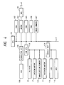
- Fig. 4 shows an example of the circuit of the facsimile apparatus embodying the present invention, wherein shown are a main CPU (central processing unit) 101 such as a microcomputer for controlling, through a bus 117, the entire apparatus for data transmission and reception; a ROM (read-only memory) 102 for storing various control programs for the CPU 101 as shown in Fig.
- main CPU central processing unit
- ROM read-only memory
- a work RAM (random access memory) 103 used as counters and registers of the CPU 101
- a modulator-demodulator (modem) 104 for data transmission
- a network control unit (NCU) 105 for connecting the modem 104 with a public telephone line
- a RAM 106 for registering data such as telephone numbers and abbreviated names
- an image RAM (DRAM) 107 for temporarily storing image data.
- a CCD (charge - coupled device) 108 serving as image pickup means of the original reading unit, converts an original image, focused though an imaging lens such as a rod lens array, into an electrical signal.
- a binary digitizing circuit 109 binarizes the output signal of the CCD 108.
- the recording head 20 is incorporated in a recording system, which is composed, in the present embodiment, of an ink jet recording apparatus of bubble jet type as shown in Figs. 2 and 3.
- a sub CPU 110 controls the carriage driving motor 17 for moving the recording head (20 in Fig. 2), the recovery motor 22 for driving the recovery unit 26, a non-discharge sensor 113 etc. and is provided with a ROM storing therein control programs for non-discharge check, recovery operation and image recording.
- An operation unit 114 is provided with a keyboard containing various keys 116 and a liquid crystal display unit (LCD) 115.
- LCD liquid crystal display unit
- Fig. 5A is a plan view of an example of the non-discharge detecting device employed in the present embodiment of the present invention
- Fig. 5B is a front view of a non-discharge sensor seen in a direction A shown in Fig. 5A.
- the non-discharge detecting device of the present embodiment is composed of a non-discharge detecting unit 120 and a non-discharge sensor 113.
- the non-discharge detecting unit 120 receives, instead of the ordinary recording sheet, the ink droplets discharged from the recording head 20 at the non-discharge checking operation to be explained later, and is provided, at the front part thereof, for example with a rolled sheet which can be advanced by a winding mechanism (not shown) utilizing a micromotor, or a white board (not shown) on which ink can be deposited and wiped off with an electric wiper (not shown).
- Said non-discharge detecting unit 120 is positioned either between the recording sheet guided by the platen 24 (cf. Fig. 3) and the cap 26A of the recovery unit 26 or outside said cap 26A and substantially adjacent thereto, in such a manner that said rolled sheet or white board is on the substantially same plane as the printing surface 34 of the recording sheet.
- Said non-discharge sensor 113 is provided with a photoelectric converting element array 113A for detecting, in the unit of each dot, the ink discharged from the recording head 20 and deposited on the rolled sheet or the white board of the non-discharge detecting unit 120, and said array 113A is positioned, as shown in Fig. 5B, parallel to the nozzles 13A of the recording head 20 and substantially as long as or somewhat longer than the array of said nozzles.
- Said non-discharge sensor 113 is mounted on the carriage 16 (cf. Fig. 3) and close to the recording head 20, and the photoelectric converting element array 113A is somewhat retracted from the nozzles of the recording head 20 so as not to contact with the wiper blade 31.
- a light source for illuminating said rolled sheet may be provided at the side of the non-discharge sensor 113 as in a photointerrupter, or may be positioned at the rear side of the rolled sheet or the semi-transparent white board, in which case the sensor 113 detects the transmitted light.
- Fig. 5C shows an example of the non-discharge detecting pattern to be recorded on the non-discharge detecting unit 120.
- This pattern is obtained by effecting ink discharges from the nozzles in succession, by a nozzle at a time from top to bottom, while the carriage 16 is moved from left to right along the guides 19A, 19B, toward the non-discharge detecting unit 120, wherein the hatched areas indicate the ink deposited positions, and N indicates the number of discharge openings.
- non-discharge detecting pattern is not limited to what has been explained above, and the non-discharge of ink may also be identified for example by discharging ink plural times in succession from a same discharge opening, or by simultaneously discharging ink from each of plural groups in which all the discharge openings are divided, and inspecting whether the average density is same among different groups.
- the presence of the non-discharge detecting unit 120 as shown in Fig. 5A allows to check the non-discharge without smearing the recording sheet, but it is naturally possible also to record the non-discharge detecting pattern directly on a marginal part of the recording sheet and to detect said pattern with the non-discharge sensor 113.
- Said marginal area can for example be a received message area for recording the date and time of reception and the sender of the received message.
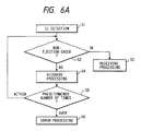
- Fig. 6A shows a main routine executed by the CPU 101
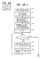
- Fig. 6B shows a non-discharge checking subroutine to be executed by the sub CPU 110.
- the main CPU 101 upon detecting a call signal Ci of 16 Hz transmitted from an external transmitter through the NCU 105 (step S1), sends an instruction for non-discharge check to the sub CPU 110 (step S2), and effects a normal reception process only after receiving, from the sub CPU 110, a non-detection (OK) communication indicating the absence of non-discharging openings (step S3).
- a call signal Ci of 16 Hz transmitted from an external transmitter through the NCU 105
- step S2 sends an instruction for non-discharge check to the sub CPU 110
- step S3 effects a normal reception process only after receiving, from the sub CPU 110, a non-detection (OK) communication indicating the absence of non-discharging openings
- step S4 an instruction for recovery process is given to the sub CPU 110 for effecting the recovery process to be explained later (step S4), and, if the number of recovery processes does not reach a predetermined number (step S5), the sequence returns to the step S2 to repeat the above-explained procedure. If non-discharging openings are still present even after the number of recovery processes exceeds the predetermined number, an error process to be explained later is executed (step S6).
- the non-discharge check and the recovery process explained above are conducted in a period after the reception of the Ci signal and before a pre-frocedure for discriminating whether or not to effect automatic reception, almost simultaneously with the checks for the presence of recording sheet and for the opened state of the cover of the recording system. Consequently, for practical purpose, the loop of aid non-discharge check and recovery process is preferably executed within a period of 10 to 15 seconds, since a period as long as 1 to 2 minutes would be inconvenient also in consideration of the convenience of the transmitting side.
- the usual head recovery process by covering the recording head 20 with the cap 26A and sucking the ink from the discharge openings by a suction motor (not shown) in the recovery unit 26, is not suitable as the recovery operation in the step S4 as it takes a relatively long time.
- the recovery process in the step S4 of the present embodiment is conducted, for example, by moving the recording head 20 by the motor 17 to the position of the cap 26A and applying drive pulses to all the heat generating elements of the discharge openings of the recording head 20, thereby effecting plural forced ink discharges, not intended for image recording, toward the cap 26A, from all the discharge openings.
- the cap 26A need not cover the recording head 20 in this operation, and said ink discharge is conducted while the cap 26A is separated from the recording head 20, and the ink discharged to said cap 26A is recovered in the recovery unit 26.
- This recovery process is similar to so-called idle ink discharge for preventing the clogging of openings, but the number of discharges is preferably about one order larger (for example 100 times) than that in the idle ink discharge. Also the number of loops in the step S5 is selected at a value matching a tolerable time (for example 15 seconds). Said number of loops in the step S5 may be directly controlled by the time by means of a timer counting the reference clock signals, instead of the count by the counter.
- the error process in the step S6 sends an error signal to the transmitting side thereby interrupting the reception, and displays a message for discharge failure on the LCD 115 of the operation unit 114 shown in Fig. 4 or flashes a lamp to inform the operator of the failure in the recording head. Preferably a buzzer sound is given simultaneously.
- the operator replaces the loaded ink jet cartridge 21 with a new one, or effects forced ink suction by the head recovery device 26 followed by a non-discharge check, and, if the recovery is not yet achieved, effects ink jet cartridge replacement.
- the non-discharge check is preferably made instructable from a key 116 of the operation unit.
- the sub CPU 110 moves the recording head 20 by the driving motor 17 to the position of the cap 26A, and applies driving pulses to all the discharge openings of the recording head 20, thereby effecting forced idle discharges for example about 10 times (step S11).
- the non-discharge detecting surface of the non-discharge detecting unit 120 shown in Fig. 5A is initialized by advancing the rolled sheet with the micromotor to expose a new sheet surface, or by cleaning the white board with the electric wiper (step S12).
- the recording head 20 is moved by the driving motor 17 and the carriage 16 to the non-discharge detecting position between the platen 24 and the recovery device 26 (step S13), and the count n of an internal counter is set at "0" (step S14).
- a non-discharge detecting pattern as shown in Fig. 5C is recorded on the non-discharge detecting surface of the non-discharge detecting unit 120.
- Fig. 5C shows a state in which discharge failure is absent in all the discharge openings.
- step S22 there is discriminated whether said count n has reached the number N of the discharge openings of the recording head 20 (step S22), and, if not, the n-th line is read by the non-discharge sensor 113 (step S23). If said line is white, namely without the discharges of ink (step S24), the detection of non-discharge is informed to the main CPU 101 (step S28). Said informing may be conducted by varying the value of a predetermined flag.
- step S24 identifies that said line is not all white, the count n of the internal counter is increased by "1" (step S25), then the driving motor 17 is activated to move the non-discharge sensor 113 by a pitch (step S26), and the sequence returns to the step S22 to repeat the above-explained procedure.
- step S27 If the count n reaches the value N through the repetition of the loop of the steps S22 to S26, all the discharge openings have normally discharged ink without failure, so that the absence of detection of the non-discharge is informed to the main CPU 101 (step S27).
- Said informing may be conducted, as explained above, by varying the value of a predetermined flag.
- control sequence of the present embodiment is shared by the main CPU 101 and the sub CPU 110, but the present invention is not limited by such embodiment and a similar control operation can naturally be conducted by a single CPU.
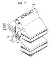
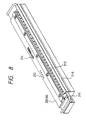
- the present invention is applicable not only to the above-explained serial printer but also to a facsimile apparatus equipped with an ink jet recording apparatus with a recording head of full-line type, having a length corresponding to the maximum width of recording medium recordable by said apparatus as shown in Figs. 7 and 8.
- paired rollers 201A, 201B for supporting and transporting a recording medium R in a sub scanning direction Vs indicated by an arrow; and full-line multi type recording heads 202BK, 202Y, 202M and 202C arranged in this order from the upstream side of the transporting direction of the recording medium R and respectively having nozzles over the entire width of the recording medium R for respectively recording black, yellow, magenta and cyan colors.
- a recovery system 200 is brought, at the discharge recovery operation, to a position opposite to the recording heads 202BK - 202C instead of the recording medium R.
- the number of such discharge recovery operations can be significantly reduced by a preliminary heating conducted at a suitable timing.
- Fig. 8 is an external view of one of the recording heads 202BK - 202C shown in Fig. 7, and shows ink discharge openings 210, an ink supply pipe 211, plural integrated circuits 212 for driving the electrothermal converting elements, and terminals 213, 214.
- Control sequences similar to those shown in Figs. 6A and 6B may also be employed in applying the present invention to a facsimile apparatus equipped with a printer of such full-line type, but, in such case, the structure can be made relatively simple by discharging the ink directly onto the recording sheet and positioning the non-discharge sensor in the down-stream side in the transporting direction of the recording sheet.
- Fig. 9 is an external perspective view of the ink jet recording apparatus of the present embodiment, wherein same components as those in Fig. 3 are represented by same numbers.
- an ink jet head 145a provided with plural ink discharge openings.
- the non-discharge sensor 113 is dispensed with, and the non-discharge check is conducted by detecting the temperature at the head drive.
- ink is suitably replenished from an unrepresented main tank to a sub tank of the ink jet head 145a, through an ink supply tube 40.
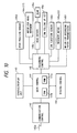
- FIG. 10 shows an example of the hardware structure of the present embodiment.
- a main control unit 141 has a CPU for controlling the various units of the apparatus, according to programs stored in a ROM 141a.
- a RAM 141b is used for temporarily storing data necessary for the function of the main control unit and for data exchange with various units.
- a communication control unit 142 controls the communication means in data communication with external equipment through a communication line, under the control of the main control unit 141.
- An operation-display unit 143 for interfacing with the operator, effects message displays to the operator and key input entries according to a control program stored in the ROM 141a.
- a reading control-unit 144 reads an original image and enters image data into the RAM 141b of the main control unit 141, in case of image data transmission from this apparatus.
- a recording control unit 145 controls a printer in recording the data entered from the communication control unit 142 or the reading control unit 144 and stored in the RAM 141b, or the data generated by the main control unit 141.
- said printer is an ink jet printer, of which an ink jet head 145a and an ink jet head driver 145b therefor are controlled by said recording control unit 145.
- the ink jet head 145a is moved by a heat moving motor 145c (corresponding to the motor 17 in Fig. 9) and the head position is confirmed by a head position sensor 145d.
- Said motor 145c and sensor 145d are also controlled by the recording control unit, which furthermore controls an ink filling circuit 145e for effecting the ink filling to the ink jet head, a sheet transport motor 145f for transporting the recording sheet, and a non-discharge sensor 145h for the ink jet head.
- the ink jet head is controlled in relation to the communication control conducted by the communication control unit.
- Fig. 11 is a block diagram of a portion of the printer relating to the detection of non-discharge of ink in the present embodiment, wherein same components as those in Fig. 10 are represented by same numbers, and a current measurement/comparator unit 146 as the ink discharge sensor 145h shown in Fig. 10.
- the current measurement/comparator unit 146 measures the current in the line 147, and, if it is smaller than a reference normal value, identifies a non-discharge and informs the same to the main control unit 141 through the recording control unit 145. In response the main control unit 141 terminates the communication through the communication control unit 142.
- said reference current value has to be determined for each cartridge, because the electric resistance may fluctuate from cartridge to cartridge.
- FIG. 12 Such embodiment is shown in Fig. 12, wherein shown are an ink jet cartridge 200 including a recording head and an ink tank as shown in Figs. 2 and 3; a current measurement unit 148 for measuring the current in a line 147; an A/D converter 149 for converting the analog data measured by said unit 148 into digital data; a memory 151 for storing the reference current value; a comparator 150 for comparing the data from the A/D converter 149 with those stored in the memory 151; and a sensor 152 for detecting whether the ink jet cartridge 200 is mounted.
- a current measurement unit 148 for measuring the current in a line 147
- an A/D converter 149 for converting the analog data measured by said unit 148 into digital data
- a memory 151 for storing the reference current value
- a comparator 150 for comparing the data from the A/D converter 149 with those stored in the memory 151
- a sensor 152 for detecting whether the ink jet cartridge 200 is mounted.
- the function is similar to that explained above, in case complete image recording is not possible due to ink discharge failure in the reception and printing of an image.
- the resistance of the ink discharging heater element of the head 201 becomes higher than in the normal state, and the current in the line 147 becomes smaller when the head driver 145b generates a pulse.
- the current measurement unit 148 measures the current in said line 147, and the A/D converter 149 converts the measured analog value into digital data.
- the comparator 150 compares thus obtained digital value with the reference current value (current at the initial ink discharge after cartridge replacement) stored in the memory 151, and, if the former is smaller, identifies a non-discharge and informs the same to the main control unit 141 through the recording control unit 145. In response the main control unit 141 terminates the communication through the communication control unit 142.
- the sensor 152 sends information on whether the ink jet cartridge 200 is mounted, through the recording control unit 145, to the main control unit 141, which checks said information at suitable timings, according to a flow chart shown in Fig. 13.
- the main control unit 141 confirms whether the ink jet cartridge is mounted (step S1), and also checks a flag indicating the presence or absence of the cartridge previously (step S2 or S6).
- the ink jet cartridge is provided with a resistor member, which forms a feedback loop upon proper mounting of the cartridge, thereby allowing to detect the mounting of the cartridge. Said flag is "1" or "0” respectively in the presence or absence of the cartridge, and is initialized to "0".
- step S7 If the ink jet cartridge is not currently mounted but the flag is “1”, it is cleared to “0” (step S7). If the ink jet cartridge is currently mounted but the flag is "0", it is set at "1" (step S3), and an instruction for an ink discharge from the recording head 20 is sent to the head driver 145b through the recording control unit 145 (step S4). In this state the current measurement unit 148 measures the current in the line 147, and the data digitized by the A/D converter 149 are stored in the memory 151 (step S5).
- the temperature change in the recording head is converted into a change in the current therein for detection, but it is also possible to mount a temperature sensor 153 on the recording head 20 as shown in Fig. 14 and to detect the non-discharge state when said sensor 153 detects that the head temperature becomes higher than the normal value.
- the above-explained embodiment is to detect the non-discharge of ink from a temperature change in the recording head and to terminate the communication in such case, thereby providing an advantage that the sender can know that exact image information cannot be obtained by the receiver.
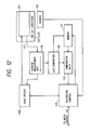
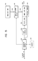
- Fig. 15 is a block diagram showing the structure for ink replenishment, wherein same components as those in Fig. 10 are represented by same numbers and will not be explained further.
- a residual amount sensor 161 for detecting the residual amount of ink in a small ink tank provided in the ink jet cartridge 200
- an ink replenishing device 162 (corresponding to the ink filling circuit 145e) for replenishing the ink from a main ink tank 163 to the ink jet cartridge 200 in response to an ink replenishing command sent from the main control unit 141 through the recording control unit 145; and ink pipes 164, 165.
- the residual ink amount sensor 161 detects such low residual amount and informs it to the main control unit 141 through the recording control unit 145.
- the main control unit 141 causes the recording head 201 to continue the image recording until the end of current communication, and, upon completion of said communication, causes the main ink tank 163 to replenish ink into the small ink tank in the ink jet cartridge 200.
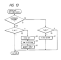
- the communication has to be terminated when said printable number of pages is exceeded, since otherwise all the pages cannot be printed.
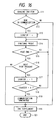
- a counter 166 for counting the number of recorded pages.
- n indicates the number of printable pages after the detection of the low residual ink amount in the ink jet cartridge 200 by the residual amount sensor 161.
- step S11 When the residual amount sensor 161 detects the low residual ink amount in the ink jet cartridge and said detection occurs in the course of a communication (steps S11, S12), a value n is set in the counter 166 (step S13) and the printing operation of the currently printed page is continued until the end of said page (steps S14, S15). Then, if a next received page is present (step S16), the count of the counter 166 is reduced by "1" (step S17). Then there is discriminated whether said count has reached "0" (step S18), and, if not, the printing operation is continued until the end of said page (step S14).
- step S19 the communication is interrupted by the communication control unit 142 (step S19) by an error process, and the ink replenishment is conducted by the ink replenishing unit 162 (step S20).
- the ink replenishment is conducted immediately if the step S12 identifies that the communication is not in progress or the step S16 identifies the absence of next page.
- the communication is interrupted when said number of pages is exceeded, so that there can be prevented the normal termination of communication without proper printing of the received images. It is also possible, instead of interrupting the communication by an error process, to store the subsequently received pages in an image memory in the step S19 (memory substituted reception), to effect the ink replenishment during said reception and to re-start the printing of the pages stored in said image memory after the completion of ink replenishment.
- the residual ink amount is detected by the residual amount sensor 161 directly attached to the recording head 201, but it is also possible to estimate the residual ink amount in the ink jet cartridge by counting the number of ink dots discharged from the head 201 by means of the main control unit 141.
- the counter 166 is shown as an independent counter, but it may be composed of a memory or a register present in the main control unit 141.
- the above-explained embodiment in which, if a low residual ink amount is detected in the course of printing operation of a received image, the ink replenishment is conducted after the termination of the communication, provides advantages of preventing an unnecessary prolongation of communication and an elevated charge for communication.
- the ink is replenished to the ink jet cartridge from the main ink tank 163 when the residual ink amount in said ink jet cartridge becomes low, but it is also possible to switch two or more recording heads according to the residual ink amount. In the following there will be explained an embodiment in which two heads are selectively switched.
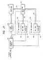
- Fig. 17 shows the structure of a printer unit employing two ink jet cartridges.
- first and second heads 20-1, 20-2 each similar to that 20 shown in Fig. 2.
- a head driver 170 switches the output drive signal, in response to a switching instruction signal supplied from the main control unit 141 through the recording control unit 145 and a signal line 172.
- bus lines 171, 173, 175 for sending head drive signals corresponding to image data; and low-ink signal lines 174, 176 for the signals released from said heads 20-1, 20-2.
- Fig. 18 shows the internal structure of the head 20-1 or 20-2, in which provided is a sensor 177 for detecting the absence of ink in the ink jet cartridge.
- the main control unit 141 decodes the image data, received from another facsimile apparatus through the communication control unit 142, into image signals and sends said image signals to the bus 171 through the recording control unit 145 for printing by the head 20-1 or 20-2.
- the head driver 170 connects the bus 171 with the bus 173 while the bus 175 is disconnected.
- the printing head IJH of the head 20-1 prints an image by discharging the ink received from the ink tank in the ink jet cartridge.
- the main control unit 141 Upon detecting the absence of ink in a step S31, the main control unit 141 interrupts the output of image signal to the bus 171 at the end of recording of a page (step S32), and sends a switching command signal to the head driver 170 through the recording control unit 145 and the switching signal line 172, in order to switch the head from 20-1 to 20-2 (step S33), for example by shifting the voltage level of the line 172 from high to low.
- the head driver 170 connects the bus 171 with 175 and disconnects the bus 173, and sends a command through the buses 171, 175 for preparing the second head 20-2 for the printing operation, such as by the idle ink discharge explained before (step S34).
- the second head 20-2 In response to said command and as soon as becoming ready for the printing operation, the second head 20-2 sends a ready command to the main control unit 141 through the buses 175, 171 and the recording control unit 145.
- the main control unit 141 Upon receiving said command (step S35), the main control unit 141 re-starts the interrupted output of the image signal to the recording control unit 145 and the bus 171 (step S36).
- the first head 20-1 terminates the image printing operation
- the second head 20-2 still containing the ink, initiates the image printing operation instead. Consequently, even when the ink runs out, the heads are automatically and promptly switched so that the communication need not be interrupted.
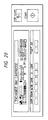
- the operation/display unit 143 displays a message as shown in Fig. 20 (step S37) informing the operator of the absence of ink in the first head 20-1 and requesting the head replacement, whereby prevented is a situation in which the printing operation is disabled by the absnece of ink in two ink jet cartridges.
- Fig. 21 shows a case in which the ink cartridge is composed solely of an ink tank and a sensor.
- a recording head 180 There are shown a recording head 180, a switching valve 182, a first ink cartridge 187, a second ink cartridge 190, ink tanks 185, 188 therein, sensors 186, 189 for detecting the absence of ink in said ink tanks 185, 188, and pipes 181, 183, 184 for supplying ink to the recording head 180.
- the switching valve 182 connects the pipe 181 with 183 and disconnects the pipe 184. If the ink runs out in the ink cartridge 187 in the course of printing of a received image, the sensor 186 sends a signal, indicating the absence of ink, to the main control unit 141, which, in response, interrupts the output of image signal after the completion of recording of a page, and sends a switching signal to the switching valve 182 for switching the ink cartridge from 187 to 190. In response the switching valve 182 connects the pipe 181 with the pipe 184 and disconnects the pipe 183. Then the main control unit 141 re-starts the interrupted output of the image signal. In this manner the interruption of the communication can be avoided even when the ink runs out, by automatic switching of ink cartridges.
- the use of plural ink cartridges with switching to another when the ink runs out in one of said cartridges in use provides an advantage of allowing to continue the communication and the printing operation, as the operator is not required an immediate cartridge replacement.
- the present invention is particularly advantageously applicable to the recording head and recording apparatus of bubble jet system, because such system has the ability of attaining higher density and definition in the recording.
- the representative structure and principle of such bubble jet system are preferably based on the basic principle disclosed for example in the U.S. Patents Nos. 4,723,129 and 4,740,796.
- This system is applicable to so-called on-demand type and continuous type ink jet recording, but is particularly effective in the on-demand recording, by providing an electrothermal converting element positioned corresponding to each liquid path or a sheet containing liquid (ink) with at least a drive signal corresponding to the recording information and inducing a rapid temperature increase exceeding nucleus boiling, thereby causing said converting element to generate thermal energy for inducing membrane boiling on a heat action surface of the recording head, thus generating a bubble in said liquid (ink) corresponding one-to-one to said drive signal.
- the liquid (ink) is discharged from a discharge opening by the expansion and contraction of said bubble, thereby forming at least a droplet.
- a pulse-shaped driven signal is particularly preferable as it achieves immediate expansion and contraction of the bubble, thereby realizing highly responsive ink discharge.
- Such pulse-shaped drive signal is preferably that disclosed in the U.S. Patents No. 4,463,359 and 4,345,262.
- a further improved recording can be achieved by the conditions disclosed in the U.S. Patent No. 4,313,124 concerning the temperature increase rate of said thermal action surface.
- the present invention includes the structures of the recording head not only obtained by the combinations of discharge openings, liquid paths and electrothermal converting members disclosed in the above-mentioned patents (those with linear or rectangularly bent liquid paths), but also the structures disclosed in the U.S. Patents Nos. 4,558,333 and 4,459,600 in which the thermal action portion is provided in a bent area.
- the present invention is also effective in a structure having a common slit as the discharge opening for plural electrothermal converting elements as disclosed in the Japanese Patent Appln. Laid-Open No. 59-123670 or a structure having an aperture for absorbing the pressure wave of thermal energy corresponding to the discharge opening as disclosed in the Japanese Patent Appln. Laid-Open No. 59-138461, because the recording can be securely and efficiently conducted regardless of the form of the recording head.
- recovery means or auxiliary means for the recording head such as capping means, cleaning means, pressurizing means or suction means, preliminary heating means composed of electrothermal converting elements and/or other heating elements, and means for effecting a preliminary discharge mode different from that for image recording, in order to achieve stable recording operation.
Landscapes
- Engineering & Computer Science (AREA)
- Multimedia (AREA)
- Signal Processing (AREA)
- Health & Medical Sciences (AREA)
- Biomedical Technology (AREA)
- General Health & Medical Sciences (AREA)
- Human Computer Interaction (AREA)
- Ink Jet (AREA)
Applications Claiming Priority (4)
| Application Number | Priority Date | Filing Date | Title |
|---|---|---|---|
| JP2041055A JPH03244546A (ja) | 1990-02-23 | 1990-02-23 | ファクシミリ装置 |
| JP41055/90 | 1990-02-23 | ||
| JP59689/90 | 1990-03-08 | ||
| JP2059689A JP3015060B2 (ja) | 1990-03-08 | 1990-03-08 | ファクシミリ装置 |
Publications (2)
| Publication Number | Publication Date |
|---|---|
| EP0443832A1 true EP0443832A1 (fr) | 1991-08-28 |
| EP0443832B1 EP0443832B1 (fr) | 1996-12-18 |
Family
ID=26380585
Family Applications (1)
| Application Number | Title | Priority Date | Filing Date |
|---|---|---|---|
| EP91301340A Expired - Lifetime EP0443832B1 (fr) | 1990-02-23 | 1991-02-20 | Appareil de transmission d'image |
Country Status (3)
| Country | Link |
|---|---|
| US (1) | US6123403A (fr) |
| EP (1) | EP0443832B1 (fr) |
| DE (1) | DE69123615T2 (fr) |
Cited By (18)
| Publication number | Priority date | Publication date | Assignee | Title |
|---|---|---|---|---|
| EP0559370A2 (fr) * | 1992-02-26 | 1993-09-08 | Canon Kabushiki Kaisha | Procédé pour enrégistrer des images, appareil pour ceci, et matériel enregistré par un tel appareil |
| EP0562786A2 (fr) * | 1992-03-23 | 1993-09-29 | Canon Kabushiki Kaisha | Appareil d'enregistrement à jet d'encre et méthode pour détecter la décharge de l'encre |
| EP0568283A1 (fr) * | 1992-04-27 | 1993-11-03 | Canon Kabushiki Kaisha | Dispositif et procédé d'enregistrement |
| EP0580421A2 (fr) * | 1992-07-24 | 1994-01-26 | Canon Kabushiki Kaisha | Appareil de projection de liquide et méthode |
| EP0622202A2 (fr) * | 1993-04-30 | 1994-11-02 | Hewlett-Packard Company | Imprimante thermique par jet d'encre avec algorithme de démarrage |
| EP0704307A3 (fr) * | 1994-09-30 | 1996-09-18 | Hewlett Packard Co | Système de purge sur page pour tête d'impression à jet d'encre |
| EP0732212A1 (fr) * | 1995-03-06 | 1996-09-18 | Hewlett-Packard Company | Nettoyage de tête d'impression adapté à l'usager pour des conditions d'imprimante différentes |
| EP0742101A1 (fr) * | 1992-03-23 | 1996-11-13 | Canon Kabushiki Kaisha | Méthode pour détecter la décharge de l'encre pour appareil d'enregistrement à jet d'encre |
| EP0745483A2 (fr) * | 1995-05-29 | 1996-12-04 | Canon Kabushiki Kaisha | Appareil d'enregistrement et méthode pour détecter le mauvais fonctionnement du dispositif de détection d'encre |
| EP0749842A2 (fr) * | 1995-06-21 | 1996-12-27 | Canon Kabushiki Kaisha | Dispositif d'enregistrement à jet d'encre avec détection de disfonctionnement de la décharge |
| EP0752316A1 (fr) * | 1995-07-04 | 1997-01-08 | Canon Kabushiki Kaisha | Agencement de détection de la décharge de l'encre pour un appareil d'enregistrement par jet d'encre |
| EP0778140A2 (fr) * | 1993-03-11 | 1997-06-11 | Seiko Epson Corporation | Méthode d'aspiration pour une appareil d'enregistrement à jet d'encre |
| US5894313A (en) * | 1994-03-09 | 1999-04-13 | Canon Kabushiki Kaisha | Ink-jet printing apparatus |
| US6123406A (en) * | 1996-03-06 | 2000-09-26 | Canon Kabushiki Kaisha | Printer with residual ink detection |
| WO2001021405A2 (fr) * | 1999-09-23 | 2001-03-29 | Encad, Inc. | Analyseur de gouttelettes d'encre |
| EP1103382A3 (fr) * | 1999-11-26 | 2001-07-18 | Francotyp-Postalia Aktiengesellschaft & Co. | Méthode pour la détermination du nombre d'impressions normales exécutables en utilisant une fonction de gestion de l'encre résiduelle et dispositif pour effectuer cette méthode |
| EP1147910A1 (fr) * | 2000-04-20 | 2001-10-24 | Hewlett-Packard Company, A Delaware Corporation | Méthode et appareil pour l'amélioration de la qualité d'une image dans un dispositif d'impression |
| CN102398425A (zh) * | 2010-08-31 | 2012-04-04 | 天津优思达科技有限公司 | 墨盒喷头及电路快速检测装置 |
Families Citing this family (7)
| Publication number | Priority date | Publication date | Assignee | Title |
|---|---|---|---|---|
| EP0442470B1 (fr) | 1990-02-13 | 1997-11-19 | Canon Kabushiki Kaisha | Appareil d'enregistrement par jet d'encre |
| AUPP702498A0 (en) * | 1998-11-09 | 1998-12-03 | Silverbrook Research Pty Ltd | Image creation method and apparatus (ART77) |
| EP1029682B1 (fr) * | 1999-02-17 | 2006-05-03 | Hewlett-Packard Company, A Delaware Corporation | Procédé pour l'entretien d'une tête d'impression à jet d'encre |
| US6565185B1 (en) * | 1999-09-29 | 2003-05-20 | Seiko Epson Corporation | Nozzle testing before and after nozzle cleaning |
| JP5288871B2 (ja) * | 2007-05-08 | 2013-09-11 | キヤノン株式会社 | 記録装置およびインク量の推定方法 |
| JP5394773B2 (ja) * | 2009-02-26 | 2014-01-22 | ローランドディー.ジー.株式会社 | 画像形成装置 |
| JP5177683B2 (ja) * | 2009-03-12 | 2013-04-03 | 株式会社リコー | 画像読取装置および複写機 |
Citations (5)
| Publication number | Priority date | Publication date | Assignee | Title |
|---|---|---|---|---|
| EP0039772A1 (fr) * | 1980-05-09 | 1981-11-18 | International Business Machines Corporation | Enregistreur à jet d'encre à plusieurs tuyères et procédé pour faire manoeuvrer cet enregistreur |
| US4587535A (en) * | 1983-08-25 | 1986-05-06 | Canon Kabushiki Kaisha | Liquid jet apparatus with pressure sensor for indicating absence/presence of liquid |
| US4661822A (en) * | 1985-03-11 | 1987-04-28 | Ricoh Company, Ltd. | Ink jet printer |
| US4734718A (en) * | 1985-02-13 | 1988-03-29 | Sharp Kabushiki Kaisha | Ink jet printer nozzle clog preventive apparatus |
| WO1989002827A1 (fr) * | 1987-09-25 | 1989-04-06 | Siemens Aktiengesellschaft | Procede et dispositif pour verifier automatiquement l'aptitude au fonctionnement de systemes d'impression a encre |
Family Cites Families (35)
| Publication number | Priority date | Publication date | Assignee | Title |
|---|---|---|---|---|
| JPS5932313B2 (ja) * | 1976-06-07 | 1984-08-08 | コニカ株式会社 | インクジエツト記録装置のインク通路洗浄方法 |
| US4067019A (en) * | 1976-06-14 | 1978-01-03 | International Business Machines Corporation | Impact position transducer for ink jet |
| CA1127227A (fr) * | 1977-10-03 | 1982-07-06 | Ichiro Endo | Procede d'enregistrement a jet liquide et appareil d'enregistrement |
| JPS588352B2 (ja) * | 1977-11-04 | 1983-02-15 | 株式会社リコー | インクジエツト記録装置 |
| US4330787A (en) * | 1978-10-31 | 1982-05-18 | Canon Kabushiki Kaisha | Liquid jet recording device |
| US4345262A (en) * | 1979-02-19 | 1982-08-17 | Canon Kabushiki Kaisha | Ink jet recording method |
| US4463359A (en) * | 1979-04-02 | 1984-07-31 | Canon Kabushiki Kaisha | Droplet generating method and apparatus thereof |
| US4313124A (en) * | 1979-05-18 | 1982-01-26 | Canon Kabushiki Kaisha | Liquid jet recording process and liquid jet recording head |
| JPS5624868A (en) * | 1979-08-08 | 1981-03-10 | Ricoh Co Ltd | Facsimile unit |
| JPS5648107A (en) * | 1979-09-28 | 1981-05-01 | Hitachi Ltd | Superconductive magnet |
| US4328504A (en) * | 1980-10-16 | 1982-05-04 | Ncr Corporation | Optical sensing of ink jet printing |
| US4376283A (en) * | 1980-11-03 | 1983-03-08 | Exxon Research And Engineering Co. | Method and apparatus for using a disposable ink jet assembly in a facsimile system and the like |
| US4333088A (en) * | 1980-11-03 | 1982-06-01 | Exxon Research & Engineering Co. | Disposable peristaltic pump assembly for facsimile printer |
| US4323905A (en) * | 1980-11-21 | 1982-04-06 | Ncr Corporation | Ink droplet sensing means |
| US4558333A (en) * | 1981-07-09 | 1985-12-10 | Canon Kabushiki Kaisha | Liquid jet recording head |
| JPS5869084A (ja) * | 1981-10-22 | 1983-04-25 | Ricoh Co Ltd | インキ式インパクトプリンタにおけるインキ供給装置 |
| US4484199A (en) * | 1982-03-30 | 1984-11-20 | Konishiroku Photo Industry Co., Ltd. | Method and apparatus for detecting failure of an ink jet printing device |
| JPS59123670A (ja) * | 1982-12-28 | 1984-07-17 | Canon Inc | インクジエツトヘツド |
| JPS59138461A (ja) * | 1983-01-28 | 1984-08-08 | Canon Inc | 液体噴射記録装置 |
| DE3428434C2 (de) * | 1983-08-02 | 1995-09-14 | Canon Kk | Druckvorrichtung |
| JPS60224552A (ja) * | 1984-04-20 | 1985-11-08 | Konishiroku Photo Ind Co Ltd | インクジエツト記録方法及び装置 |
| JPS60224549A (ja) * | 1984-04-23 | 1985-11-08 | Canon Inc | インクジエツトプリンタ |
| JPS60253552A (ja) * | 1984-05-29 | 1985-12-14 | Konishiroku Photo Ind Co Ltd | インクジエツト記録装置 |
| GB2166619B (en) * | 1984-09-28 | 1988-12-07 | Canon Kk | Image processing apparatus |
| JPS6198040A (ja) * | 1984-10-19 | 1986-05-16 | Fujitsu Ltd | 親局・子局間配線処理方式 |
| US4999643A (en) * | 1984-11-19 | 1991-03-12 | Canon Kabushiki Kaisha | Discharge recovery device and apparatus having suction means and vent means communicating with capping means |
| JPS6331934A (ja) * | 1986-07-24 | 1988-02-10 | Nikon Corp | ウエハ又はウエハキヤリアのインライン搬送装置 |
| JP2708439B2 (ja) * | 1987-11-17 | 1998-02-04 | キヤノン株式会社 | インクジェットプリンタ |
| DE3882662T2 (de) * | 1987-11-27 | 1994-01-05 | Canon Kk | Tintenstrahlaufzeichnungsvorrichtung. |
| JP2727197B2 (ja) * | 1988-05-25 | 1998-03-11 | キヤノン株式会社 | インクジェット記録装置 |
| US5140429A (en) * | 1988-06-23 | 1992-08-18 | Canon Kabushiki Kaisha | Ink-jet recording apparatus with mechanism for automatically regulating a recording head |
| US4972270A (en) * | 1989-04-17 | 1990-11-20 | Stephen Kurtin | Facsimile recorder with acutely mounted staggered array ink jet printhead |
| JPH032040A (ja) * | 1989-05-31 | 1991-01-08 | Canon Inc | インクジェット記録装置 |
| JP2804568B2 (ja) * | 1989-12-25 | 1998-09-30 | 株式会社リコー | 画像読取装置 |
| JPH0453929A (ja) * | 1990-06-22 | 1992-02-21 | Fujitsu Ltd | 反射型液晶装置 |
-
1991
- 1991-02-20 EP EP91301340A patent/EP0443832B1/fr not_active Expired - Lifetime
- 1991-02-20 DE DE69123615T patent/DE69123615T2/de not_active Expired - Lifetime
-
1993
- 1993-07-19 US US08/092,937 patent/US6123403A/en not_active Expired - Lifetime
Patent Citations (5)
| Publication number | Priority date | Publication date | Assignee | Title |
|---|---|---|---|---|
| EP0039772A1 (fr) * | 1980-05-09 | 1981-11-18 | International Business Machines Corporation | Enregistreur à jet d'encre à plusieurs tuyères et procédé pour faire manoeuvrer cet enregistreur |
| US4587535A (en) * | 1983-08-25 | 1986-05-06 | Canon Kabushiki Kaisha | Liquid jet apparatus with pressure sensor for indicating absence/presence of liquid |
| US4734718A (en) * | 1985-02-13 | 1988-03-29 | Sharp Kabushiki Kaisha | Ink jet printer nozzle clog preventive apparatus |
| US4661822A (en) * | 1985-03-11 | 1987-04-28 | Ricoh Company, Ltd. | Ink jet printer |
| WO1989002827A1 (fr) * | 1987-09-25 | 1989-04-06 | Siemens Aktiengesellschaft | Procede et dispositif pour verifier automatiquement l'aptitude au fonctionnement de systemes d'impression a encre |
Cited By (49)
| Publication number | Priority date | Publication date | Assignee | Title |
|---|---|---|---|---|
| US6036300A (en) * | 1992-02-26 | 2000-03-14 | Canon Kabushiki Kaisha | Method for recording image and apparatus therefor and recorded matter by such an apparatus |
| US6863371B2 (en) | 1992-02-26 | 2005-03-08 | Canon Kabushiki Kaisha | Image recording apparatus for recording an image on a recording medium |
| EP0559370A3 (fr) * | 1992-02-26 | 1993-10-27 | Canon Kabushiki Kaisha | Procédé pour enrégistrer des images, appareil pour ceci, et matériel enregistré par un tel appareil |
| US7556345B2 (en) | 1992-02-26 | 2009-07-07 | Canon Kabushiki Kaisha | Image recording apparatus and method for recording an image on a recording medium |
| US6547361B1 (en) | 1992-02-26 | 2003-04-15 | Canon Kabushiki Kaisha | Image recording apparatus which compensates for a defective recording area |
| EP0559370A2 (fr) * | 1992-02-26 | 1993-09-08 | Canon Kabushiki Kaisha | Procédé pour enrégistrer des images, appareil pour ceci, et matériel enregistré par un tel appareil |
| US6048046A (en) * | 1992-03-23 | 2000-04-11 | Canon Kabushiki Kaisha | Ink discharge detecting method for an ink jet recording apparatus, said ink jet recording apparatus and an image forming device using said ink jet recording apparatus |
| US5508722A (en) * | 1992-03-23 | 1996-04-16 | Canon Kabushiki Kaisha | Ink jet apparatus and method for detecting ink nondischarge based on ink temperature |
| EP0742101A1 (fr) * | 1992-03-23 | 1996-11-13 | Canon Kabushiki Kaisha | Méthode pour détecter la décharge de l'encre pour appareil d'enregistrement à jet d'encre |
| EP0562786A3 (en) * | 1992-03-23 | 1994-06-01 | Canon Kk | Ink jet recording apparatus and ink discharge detecting method for said apparatus |
| EP0562786A2 (fr) * | 1992-03-23 | 1993-09-29 | Canon Kabushiki Kaisha | Appareil d'enregistrement à jet d'encre et méthode pour détecter la décharge de l'encre |
| US6168261B1 (en) | 1992-04-27 | 2001-01-02 | Canon Kabushiki Kaisha | Recording apparatus and recording method |
| EP0918432A3 (fr) * | 1992-04-27 | 1999-06-16 | Canon Kabushiki Kaisha | Dispositif et procédé d'enregistrement |
| EP0918432A2 (fr) * | 1992-04-27 | 1999-05-26 | Canon Kabushiki Kaisha | Dispositif et procédé d'enregistrement |
| EP0568283A1 (fr) * | 1992-04-27 | 1993-11-03 | Canon Kabushiki Kaisha | Dispositif et procédé d'enregistrement |
| US6174039B1 (en) | 1992-04-27 | 2001-01-16 | Canon Kabushiki Kaisha | Recording apparatus and recording method |
| EP0580421A3 (fr) * | 1992-07-24 | 1994-12-21 | Canon Kk | Appareil de projection de liquide et méthode. |
| US5742302A (en) * | 1992-07-24 | 1998-04-21 | Canon Kabushiki Kaisha | Liquid jetting apparatus and method of controlling recovery based on detection of mounted head |
| EP0580421A2 (fr) * | 1992-07-24 | 1994-01-26 | Canon Kabushiki Kaisha | Appareil de projection de liquide et méthode |
| EP1000747A1 (fr) * | 1993-03-11 | 2000-05-17 | Seiko Epson Corporation | Appareil d'enregistrement à jet d'encre |
| EP0778140A2 (fr) * | 1993-03-11 | 1997-06-11 | Seiko Epson Corporation | Méthode d'aspiration pour une appareil d'enregistrement à jet d'encre |
| EP0778140A3 (fr) * | 1993-03-11 | 1997-11-12 | Seiko Epson Corporation | Méthode d'aspiration pour une appareil d'enregistrement à jet d'encre |
| US6019450A (en) * | 1993-03-11 | 2000-02-01 | Seiko Epson Corporation | Ink jet recording apparatus |
| EP0622202A2 (fr) * | 1993-04-30 | 1994-11-02 | Hewlett-Packard Company | Imprimante thermique par jet d'encre avec algorithme de démarrage |
| EP0622202A3 (fr) * | 1993-04-30 | 1997-10-22 | Hewlett Packard Co | Imprimante thermique par jet d'encre avec algorithme de démarrage. |
| US5894313A (en) * | 1994-03-09 | 1999-04-13 | Canon Kabushiki Kaisha | Ink-jet printing apparatus |
| EP0704307A3 (fr) * | 1994-09-30 | 1996-09-18 | Hewlett Packard Co | Système de purge sur page pour tête d'impression à jet d'encre |
| US5659342A (en) * | 1994-09-30 | 1997-08-19 | Hewlett-Packard Company | On-page inkjet printhead spitting system |
| US5793388A (en) * | 1995-03-06 | 1998-08-11 | Hewlett-Packard Company | Customized printhead servicing for different printer conditions |
| EP0732212A1 (fr) * | 1995-03-06 | 1996-09-18 | Hewlett-Packard Company | Nettoyage de tête d'impression adapté à l'usager pour des conditions d'imprimante différentes |
| EP0745483A2 (fr) * | 1995-05-29 | 1996-12-04 | Canon Kabushiki Kaisha | Appareil d'enregistrement et méthode pour détecter le mauvais fonctionnement du dispositif de détection d'encre |
| US5963225A (en) * | 1995-05-29 | 1999-10-05 | Canon Kabushiki Kaisha | Recording apparatus and method of detecting malfunction of ink detection means |
| EP0745483A3 (fr) * | 1995-05-29 | 1997-07-16 | Canon Kk | Appareil d'enregistrement et méthode pour détecter le mauvais fonctionnement du dispositif de détection d'encre |
| US6130682A (en) * | 1995-06-21 | 2000-10-10 | Canon Kabushiki Kaisha | Ink jet recording apparatus with detection of discharge malfunction |
| EP0749842A3 (fr) * | 1995-06-21 | 1998-01-21 | Canon Kabushiki Kaisha | Dispositif d'enregistrement à jet d'encre avec détection de disfonctionnement de la décharge |
| EP0749842A2 (fr) * | 1995-06-21 | 1996-12-27 | Canon Kabushiki Kaisha | Dispositif d'enregistrement à jet d'encre avec détection de disfonctionnement de la décharge |
| US6312086B1 (en) | 1995-07-04 | 2001-11-06 | Canon Kabushiki Kaisha | Ink jet recording apparatus having separately disposed recovery and ink detection devices |
| EP0752316A1 (fr) * | 1995-07-04 | 1997-01-08 | Canon Kabushiki Kaisha | Agencement de détection de la décharge de l'encre pour un appareil d'enregistrement par jet d'encre |
| US6123406A (en) * | 1996-03-06 | 2000-09-26 | Canon Kabushiki Kaisha | Printer with residual ink detection |
| WO2001021405A2 (fr) * | 1999-09-23 | 2001-03-29 | Encad, Inc. | Analyseur de gouttelettes d'encre |
| US6347857B1 (en) | 1999-09-23 | 2002-02-19 | Encad, Inc. | Ink droplet analysis apparatus |
| WO2001021405A3 (fr) * | 1999-09-23 | 2001-10-18 | Encad Inc | Analyseur de gouttelettes d'encre |
| US6428132B1 (en) | 1999-11-26 | 2002-08-06 | Francotyp-Postalia Ag & Co. | Method for determining the number of normal imprints implementable with a remaining ink quantity and arrangement for the implementation of the method |
| DE19958948B4 (de) * | 1999-11-26 | 2005-06-02 | Francotyp-Postalia Ag & Co. Kg | Verfahren zur Bestimmung der Anzahl von mit einer Tintenrestmenge ausführbaren Drucken und Vorrichtung zur Durchführung des Verfahrens |
| EP1103382A3 (fr) * | 1999-11-26 | 2001-07-18 | Francotyp-Postalia Aktiengesellschaft & Co. | Méthode pour la détermination du nombre d'impressions normales exécutables en utilisant une fonction de gestion de l'encre résiduelle et dispositif pour effectuer cette méthode |
| EP1147910A1 (fr) * | 2000-04-20 | 2001-10-24 | Hewlett-Packard Company, A Delaware Corporation | Méthode et appareil pour l'amélioration de la qualité d'une image dans un dispositif d'impression |
| US6652064B2 (en) | 2000-04-20 | 2003-11-25 | Hewlett-Packard Development Company, L.P. | Method for improving image quality on plots |
| EP1577108A3 (fr) * | 2000-04-20 | 2007-08-08 | Hewlett-Packard Company | Méthode de remise en état d'une tête d'impression montée dans un dispositif d'impression |
| CN102398425A (zh) * | 2010-08-31 | 2012-04-04 | 天津优思达科技有限公司 | 墨盒喷头及电路快速检测装置 |
Also Published As
| Publication number | Publication date |
|---|---|
| US6123403A (en) | 2000-09-26 |
| DE69123615D1 (de) | 1997-01-30 |
| EP0443832B1 (fr) | 1996-12-18 |
| DE69123615T2 (de) | 1997-04-24 |
Similar Documents
| Publication | Publication Date | Title |
|---|---|---|
| US6123403A (en) | Image communicating apparatus controlling data reception based on number of non-discharge condition | |
| US6050669A (en) | Method of controlling an ink-jet recording apparatus according to recording apparatus in which the method is implemented | |
| US5631674A (en) | Recording apparatus | |
| US8651616B2 (en) | Printing apparatus and ink remaining amount detection method | |
| US6048045A (en) | Printer and facsimile apparatus that can test for a proper functioning ink jet nozzle without printing a test pattern | |
| EP0657290B1 (fr) | Appareil d'enregistrement à jet d'encre utilisant l'énergie thermique et méthode de l'utilisation | |
| EP0442438B1 (fr) | Appareil d'enregistrement par jet d'encre | |
| EP0443808B1 (fr) | Appareil de communication d'image | |
| US5249062A (en) | Image communication using ink jet recorder with heat fusing device | |
| US5175566A (en) | Image communicating apparatus with ink jet printer having controlled capping operation | |
| EP0643526A1 (fr) | Appareil d'enregistrement d'images et procédé de commutation de mode dans cet appareil | |
| EP0443716B1 (fr) | Dispositif de communication d'images | |
| EP0576285A2 (fr) | Méthode et appareil pour l'enregistrement à jet d'encre | |
| US5822076A (en) | Facsimile apparatus with ink cartridge and residual ink detection function | |
| EP0443247B1 (fr) | Dispositif de communication d'images | |
| EP0616896B1 (fr) | Dispositif d'enregistrement d'images | |
| EP0443872B1 (fr) | Système de transmission d'images | |
| US5777633A (en) | Image communicating apparatus with ink jet printer having controlled capping operation | |
| JP3530635B2 (ja) | 記録方法及びその記録装置 | |
| EP0443833B1 (fr) | Dispositif de communication d'images | |
| JP2001150697A (ja) | 走査装置 | |
| JPH03244547A (ja) | ファクシミリ装置 | |
| JPH0969895A (ja) | 画像記録装置 | |
| JP2004202781A (ja) | インクタンク交換の検出方法 | |
| JPH08332734A (ja) | インクジェット記録装置 |
Legal Events
| Date | Code | Title | Description |
|---|---|---|---|
| PUAI | Public reference made under article 153(3) epc to a published international application that has entered the european phase |
Free format text: ORIGINAL CODE: 0009012 |
|
| AK | Designated contracting states |
Kind code of ref document: A1 Designated state(s): DE ES FR GB IT |
|
| 17P | Request for examination filed |
Effective date: 19920113 |
|
| 17Q | First examination report despatched |
Effective date: 19931223 |
|
| GRAH | Despatch of communication of intention to grant a patent |
Free format text: ORIGINAL CODE: EPIDOS IGRA |
|
| GRAH | Despatch of communication of intention to grant a patent |
Free format text: ORIGINAL CODE: EPIDOS IGRA |
|
| GRAA | (expected) grant |
Free format text: ORIGINAL CODE: 0009210 |
|
| AK | Designated contracting states |
Kind code of ref document: B1 Designated state(s): DE ES FR GB IT |
|
| PG25 | Lapsed in a contracting state [announced via postgrant information from national office to epo] |
Ref country code: ES Free format text: THE PATENT HAS BEEN ANNULLED BY A DECISION OF A NATIONAL AUTHORITY Effective date: 19961218 |
|
| REF | Corresponds to: |
Ref document number: 69123615 Country of ref document: DE Date of ref document: 19970130 |
|
| ET | Fr: translation filed | ||
| ITF | It: translation for a ep patent filed | ||
| PLBE | No opposition filed within time limit |
Free format text: ORIGINAL CODE: 0009261 |
|
| STAA | Information on the status of an ep patent application or granted ep patent |
Free format text: STATUS: NO OPPOSITION FILED WITHIN TIME LIMIT |
|
| 26N | No opposition filed | ||
| REG | Reference to a national code |
Ref country code: GB Ref legal event code: IF02 |
|
| PGFP | Annual fee paid to national office [announced via postgrant information from national office to epo] |
Ref country code: IT Payment date: 20090205 Year of fee payment: 19 |
|
| PGFP | Annual fee paid to national office [announced via postgrant information from national office to epo] |
Ref country code: FR Payment date: 20090223 Year of fee payment: 19 |
|
| PGFP | Annual fee paid to national office [announced via postgrant information from national office to epo] |
Ref country code: DE Payment date: 20100228 Year of fee payment: 20 Ref country code: GB Payment date: 20100219 Year of fee payment: 20 |
|
| REG | Reference to a national code |
Ref country code: FR Ref legal event code: ST Effective date: 20101029 |
|
| PG25 | Lapsed in a contracting state [announced via postgrant information from national office to epo] |
Ref country code: FR Free format text: LAPSE BECAUSE OF NON-PAYMENT OF DUE FEES Effective date: 20100301 |
|
| REG | Reference to a national code |
Ref country code: DE Ref legal event code: R071 Ref document number: 69123615 Country of ref document: DE |
|
| REG | Reference to a national code |
Ref country code: GB Ref legal event code: PE20 Expiry date: 20110219 |
|
| PG25 | Lapsed in a contracting state [announced via postgrant information from national office to epo] |
Ref country code: IT Free format text: LAPSE BECAUSE OF NON-PAYMENT OF DUE FEES Effective date: 20100220 |
|
| PG25 | Lapsed in a contracting state [announced via postgrant information from national office to epo] |
Ref country code: GB Free format text: LAPSE BECAUSE OF EXPIRATION OF PROTECTION Effective date: 20110219 |
|
| PG25 | Lapsed in a contracting state [announced via postgrant information from national office to epo] |
Ref country code: DE Free format text: LAPSE BECAUSE OF EXPIRATION OF PROTECTION Effective date: 20110220 |