EP0443808B1 - Appareil de communication d'image - Google Patents
Appareil de communication d'image Download PDFInfo
- Publication number
- EP0443808B1 EP0443808B1 EP91301300A EP91301300A EP0443808B1 EP 0443808 B1 EP0443808 B1 EP 0443808B1 EP 91301300 A EP91301300 A EP 91301300A EP 91301300 A EP91301300 A EP 91301300A EP 0443808 B1 EP0443808 B1 EP 0443808B1
- Authority
- EP
- European Patent Office
- Prior art keywords
- discharge
- data
- ink
- recording
- image
- Prior art date
- Legal status (The legal status is an assumption and is not a legal conclusion. Google has not performed a legal analysis and makes no representation as to the accuracy of the status listed.)
- Expired - Lifetime
Links
Images


Classifications
-
- B—PERFORMING OPERATIONS; TRANSPORTING
- B41—PRINTING; LINING MACHINES; TYPEWRITERS; STAMPS
- B41J—TYPEWRITERS; SELECTIVE PRINTING MECHANISMS, i.e. MECHANISMS PRINTING OTHERWISE THAN FROM A FORME; CORRECTION OF TYPOGRAPHICAL ERRORS
- B41J2/00—Typewriters or selective printing mechanisms characterised by the printing or marking process for which they are designed
- B41J2/005—Typewriters or selective printing mechanisms characterised by the printing or marking process for which they are designed characterised by bringing liquid or particles selectively into contact with a printing material
- B41J2/01—Ink jet
- B41J2/135—Nozzles
- B41J2/165—Preventing or detecting of nozzle clogging, e.g. cleaning, capping or moistening for nozzles
- B41J2/16579—Detection means therefor, e.g. for nozzle clogging
-
- B—PERFORMING OPERATIONS; TRANSPORTING
- B41—PRINTING; LINING MACHINES; TYPEWRITERS; STAMPS
- B41J—TYPEWRITERS; SELECTIVE PRINTING MECHANISMS, i.e. MECHANISMS PRINTING OTHERWISE THAN FROM A FORME; CORRECTION OF TYPOGRAPHICAL ERRORS
- B41J2/00—Typewriters or selective printing mechanisms characterised by the printing or marking process for which they are designed
- B41J2/005—Typewriters or selective printing mechanisms characterised by the printing or marking process for which they are designed characterised by bringing liquid or particles selectively into contact with a printing material
- B41J2/01—Ink jet
- B41J2/135—Nozzles
- B41J2/165—Preventing or detecting of nozzle clogging, e.g. cleaning, capping or moistening for nozzles
- B41J2/16517—Cleaning of print head nozzles
- B41J2/1652—Cleaning of print head nozzles by driving a fluid through the nozzles to the outside thereof, e.g. by applying pressure to the inside or vacuum at the outside of the print head
-
- B—PERFORMING OPERATIONS; TRANSPORTING
- B41—PRINTING; LINING MACHINES; TYPEWRITERS; STAMPS
- B41J—TYPEWRITERS; SELECTIVE PRINTING MECHANISMS, i.e. MECHANISMS PRINTING OTHERWISE THAN FROM A FORME; CORRECTION OF TYPOGRAPHICAL ERRORS
- B41J2/00—Typewriters or selective printing mechanisms characterised by the printing or marking process for which they are designed
- B41J2/005—Typewriters or selective printing mechanisms characterised by the printing or marking process for which they are designed characterised by bringing liquid or particles selectively into contact with a printing material
- B41J2/01—Ink jet
- B41J2/21—Ink jet for multi-colour printing
- B41J2/2132—Print quality control characterised by dot disposition, e.g. for reducing white stripes or banding
- B41J2/2146—Print quality control characterised by dot disposition, e.g. for reducing white stripes or banding for line print heads
Definitions
- the present invention relates to an image communicating apparatus such as a facsimile apparatus, and more particularly to an image communicating apparatus equipped with an ink jet printer provided with plural ink discharge openings (orifices).
- a facsimile apparatus is required not only to transmit an image at a high speed, but also to receive the image with a high image quality and a high speed.
- the ink jet printer of the method discharging the ink toward the recording material utilizing the bubbles generated by thermal energy is considered as one of the printers capable of meeting such requirements, but there has not been provided a facsimile apparatus equipped with such an ink jet printer.
- the ink discharge openings of the recording head may be clogged by the ink which is viscosified by a pause in the use of the recording head, or in a low humidity situation or by a difference in the frequency of use, or by the deposition of dusts.
- a discharge recovery mechanism for removing such viscosified ink by pressurizing the discharge openings from the interior of the recording head, or by sucking said ink from a protective cap for covering the discharge openings of the recording head.
- the frequency of ink discharges is not uniform among the discharge openings, so that some openings may never be used and those used infrequently may cause clogging. Since such clogging deteriorates the image quality, the discharge recovery process is generally conducted at a regular interval, and for this purpose there is provided an interruption timer for interruption process.
- a concern of the present invention is to provide an improved image communicating apparatus.
- Another concern of the present invention is to provide an image communicating apparatus capable of constantly stable recording.
- Still another concern of the present invention is to provide an image communicating apparatus capable of conducting the ink discharge recovery process at secure timings for idle discharge, without particular timer interruption process.
- Still another concern of the present invention is to provide an image communicating apparatus utilizing a fact that the number of received data per unit time is determined by the data receiving rate of the image signal without any practical fluctuation.
- Still another concern of the present invention is to provide an image communicating apparatus capable of obtaining secure timings of idle discharge by defining said timing from the data receiving rate and the number of actually received data, without requiring a particular timer interruption process.
- Still another concern of the present invention is to provide an image communicating apparatus not requiring an interruption process for the idle ink discharge, thereby improving the performance with reduced burden on the central processing unit and with simplified control program.
- Still another concern of the present invention is to provide an image communicating apparatus in which the timing of idle discharge is instructed according to the data receiving rate of image and the number of actually received data, and at least an ink discharge not intended for image recording is conducted in all the ink discharge openings at thus instructed timing of idle discharge.
- an image communicating apparatus as defined in claim 1.
- Fig. 1 shows the basic structure of an embodiment of the present invention, wherein provided instruction means A for instructing the timing of idle ink discharge based on the data receiving rate of image and the number of actually received data; and idle discharge means B for effecting at least an idle ink discharge, not intended for image recording, from all the discharge openings of the recording head at the timing instructed by said instruction means A.
- FIGs. 2 and 3 illustrate an example of ink jet printer adapted for use as the recording system in a facsimile apparatus embodying the present invention.
- the ink jet head IJH slightly protrudes from the front face of the ink tank IT.
- Said ink jet cartridge IJC is of disposable type, detachably mounted on a carriage of the ink jet recording apparatus IJRA as will be explained later.
- a first ink tank IT containing ink for supply to the ink jet head IJH, is composed of an ink absorbent member, a container therefor and a cover member for closing said container (these members not shown). Said ink tank IT (10) is filled with ink and supplies said ink to the ink jet head according to ink discharge therefrom.
- a front plate 4 is composed of a resinous material with high ink resistance, such as polysulfone, polyethersulfone, polyphenylene oxide or polypropylene.
- the ink jet cartridge IJC of the above-explained structure is detachably mounted on the carriage HC of the ink jet recording apparatus IJRA explained in the following, and effects formation of a recorded image by relative movement of the carriage HC and a recording material, in response to the entry of a recording signal.
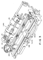
- Fig. 3 is a perspective view of an example of the ink jet recording apparatus IJRA equipped with mechanisms for the above-mentioned operations.
- the ink jet head (recording head) 20 of the ink jet cartridge IJC is provided with nozzles for discharging ink toward a recording surface of a recording sheet supplied from a sheet feeding unit 25 onto a platen 24.
- a carriage (HC) 16, for supporting said recording head 20 is linked with a part of a driving belt 18 for transmitting the driving power of a driving motor 17, and is capable of reciprocating over the entire width of the recording sheet by sliding along mutually parallel two guide shafts 19A, 19B.
- a discharge recovery operation by ink suction (suction recovery) by suitable suction means (for example a suction pump) provided in the recovery unit 26 or by forced discharge of viscosified ink from the discharge openings by pressurizing ink with suitable pressurizing means provided in an ink supply path to the recording head 20 (pressurized recovery).
- suction recovery by suitable suction means (for example a suction pump) provided in the recovery unit 26 or by forced discharge of viscosified ink from the discharge openings by pressurizing ink with suitable pressurizing means provided in an ink supply path to the recording head 20 (pressurized recovery).
- the recording head is protected by said capping for example after the recording operation.
- Such discharge recovery operation is conducted at the start of power supply, at the replacement of the recording head, or at
- the blade 31 is made to protrude into the moving path of the recording head 20 at a suitable timing in the course of recording operation thereof or after the discharge recovery operation therefor by the recovery unit 26, thereby wiping the dew, liquid or dusts off said ink discharging surface of the recording head 20 by the movement thereof.
- Fig. 4 shows an example of the circuit of the facsimile apparatus embodying the present invention, wherein shown are a main CPU (central processing unit) 101 such as a microcomputer for controlling, through a bus 117, the entire apparatus for data transmission and reception; an ROM (read-only memory) 102 for storing various control programs for the CPU 101 as shown in Fig.
- a main CPU central processing unit
- ROM read-only memory
- a work RAM random access memory
- MODEM modulator-demodulator
- NCU network control unit
- NCU network control unit
- RAM 106 for registering data such as telephone numbers and abbreviated names
- DRAM image RAM
- a CCD (charge-coupled device) 108 serving as image pickup means of the original reading unit, converts an original image, focused through an imaging lens such as a rod lens array, into an electrical signal.
- a binary digitizing circuit 109 binarizes the output signal of the CCD 108.
- the recording head 111 is incorporated in a recording system, which is composed, in the present embodiment of an ink jet recording apparatus of a type discharging ink utilizing thermal energy as shown in Figs. 2 and 3.
- a sub CPU 110 controls the ink jet head 111, a motor 17 for driving the carriage, a motor 22 for driving the recovery unit 26, a non-discharge sensor 113 etc. and is provided therein with an ROM for storing control programs for image recording as shown in Fig. 6.
- An operation unit 114 is provided with a keyboard containing various keys 116 and a liquid crystal display unit (LCD) 115.
- LCD liquid crystal display unit
- Fig. 5 shows the control sequence to be executed by the main CPU 101 shown in Fig. 4.
- a preliminary procedure for data reception is completed according to a communication protocol such as G3 (step S1)
- a number d of received data is set as "1200" for a data receiving rate of 9600 bps (bits/sec) (step S2).
- the product of said received data number d and a desired idle discharge cycle (sec) is stored in a counter T.
- a counter resetting register Torg a flag register Flag is turned off, and a line counter LINE is set at "0" (step S3).
- step S4 the count of said counter T is discriminated (step S4), and, if it is zero, the sequence proceeds to a step S9 to be explained later. If said count is larger than zero, the compression encoded image data, which are demodulated in the modem 104, are read therefrom (step S5), and the count of the counter T is decreased by "1" for the reading of every one byte of said compression encoded image data. In this operation, the control codes, such as EOL (end of line) code, included in the image data are also counted (step S6).
- EOL end of line
- step S7 it is discriminated whether the compression encoded image data, thus read, has reached a final print line.
- Said line is calculated in the unit of dots corresponding to the ink discharge openings in the sub scanning direction, and, for example in the A4 size, data of 1728 dots in the main scanning direction constitute a line (step S7). If the data amount does not reach a line, the sequence returns to the step S4 to repeat the above-explained procedure. If the data amount has reached a line, the count of the line counter LINE is increased by "1" (step S8), and the sequence returns to said step S4 to repeat the above-explained sequence.
- the step S9 discriminates whether the flag Flag for instructing the idle discharge is off, and, if it is off, said flag is turned on for instructing the idle discharge (step S10). Then the count of the counter T is reset to the value of the register Torg, namely to the initial value (step S11), and the sequence returns to the step S4.
- step S9 if the step S9 identifies that said flag Flag is not off, there is identified an abnormal state in which the recording head 111 has not executed a proper idle discharge in response to the previous instruction therefor (cf. step S26 in Fig. 6) and an error process is executed. Said error process interrupts the printing operation or the communication, and displays an error message on the LCD 115. Also the operator confirms the print state by a non-discharge checking operation (step S12).
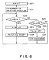
- Fig. 6 shows the control sequence to be executed by the sub CPU 110 for controlling the recording system.
- a serial printer as shown in Fig. 3, and the sequence shown in Fig. 6 is executed simultaneously with and independently from the control sequence of the CPU 101 shown in Fig. 5.
- the number of ink discharge openings also called print nozzle number
- N the number of ink discharge openings in the sub scanning direction of the recording head 111 is set in a register N (step S21).
- Said value N indicates the number of lines, in the unit of dots, recordable by the recording head at a time, and, for example, N is set as "50" if the recording head 111 has 50 discharge openings in the sub scanning direction.
- Said number N is usually fixed, but, in the present embodiment, even if the recording head is changed to another with different number of discharge openings, such change can be easily coped with by a change in the number N in the step S21.
- step S22 it is discriminated whether the count of the line counter LINE shown in Fig. 5 coincides with that of the register (step S22), and, if not, the sequence proceeds to a step S25 to be explained later. If that discrimination establishes such coincidence, thus indicating that image data for a scanning motion of the recording head have been read, the line counter LINE is reset to "0" (step S23), then the printing operation is started by controlling the recording head 111 and the driving motor 17 (step S24), and the sequence returns to the step S22.
- step S22 identifies that the count of the counter LINE does not coincide with that of the register N
- step S25 discriminates whether the flag FLAG shown in Fig. 5 is on, and, if not, where the idle discharge has not been instructed, the sequence returns to the step S22 to repeat the above-explained sequence.
- said Flag is on, indicating that the idle discharge has been instructed, said Flag is reset to "off" (step S26), then an idle discharge process is conducted (step S27), and the sequence returns to said step S22.
- the idle discharge operation in said step S27 is conducted for example in the following manner Referring to Fig. 3, the recording head 20 is moved by the motor 17 to the position of the cap 26A in response to an instruction for idle discharge, and drive pulses are uniformly applied to the heat generating members of all the discharge openings of said recording head 20, thereby effecting forced ink discharges not intended for image recording (thus called idle discharges) of about 10 times from all the discharge openings, toward the cap 26A.
- the cap 26A need not cover the recording head 20 but may be separated therefrom, and the ink discharged into the cap 26A is collected in the recovery unit 26.
- control sequence of the present embodiment is shared by the main CPU 101 and the sub CPU 110, but the present invention is not limited to such embodiment and a similar control operation can naturally be conducted by a single CPU.
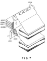
- the present invention is applicable not only to the above-explained serial printer but also to a facsimile apparatus equipped with an ink jet recording apparatus with a recording head of full-line type, having a length corresponding to the maximum width of recording medium recordable by said apparatus as shown in Figs. 7 and 8.
- paired rollers 201A, 201B for supporting and transporting a recording medium R in a sub scanning direction Y indicated by an arrow; and full-line multitype recording heads 202BK, 202Y, 202M and 202C arranged in this order from the upstream side of the transporting direction of the recording medium R and respectively having nozzles over the entire width of the recording medium R for respectively recording black, yellow, magenta and cyan colors.
- Control sequences shown in Figs. 5 and 6 are also usable in case of applying the present invention to a facsimile apparatus equipped with a printer of such full-line type.
- the value N in the step S21 in Fig. 6 indicates the number of lines (in the unit of dots) scanned by the recording head at a time in the sub scanning direction, and may be equal to "1".
- the present invention is also applicable to a facsimile apparatus employing an ink jet recording apparatus of so-called piezo type, utilizing piezoelectric elements as the source of energy for ink discharge.
- the present invention is particularly advantageously applicable to the recording head and recording apparatus of a bubble jet system, because such system has the ability of attaining higher density and definition in the recording.
- the representative structure and principle of such a bubble jet system are preferably based on the basic principle disclosed for example in U.S. Patents Nos. 4,723,129 and 4,740,796.
- This system is applicable to a so-called on-demand type and continuous type ink jet recording, but is particularly effective in the on-demand recording by providing an electrothermal converting element positioned corresponding to each liquid path or sheet containing liquid (ink) with at least a drive signal corresponding to the recording information and inducing a rapid temperature increase exceeding nucleate boiling, thereby causing said converting element to generate thermal energy for inducing membrance boiling on a heat action surface of the recording head, thus generating a bubble in said liquid (ink) corresponding one-to-one to said drive signal.
- the liquid (ink) is discharged from a discharge opening by the expansion and contraction of said bubble, thereby forming at least a droplet.
- a pulse-shaped drive signal is particularly preferable as it achieves immediate expansion and contraction of the bubble, thereby realizing highly responsive ink discharge.
- Such pulse-shaped drive signal is preferably that disclosed in U.S. Patents Nos. 4,463,359 and 4,345,262.
- a further improved recording can be achieved by the conditions disclosed in U.S. Patent No. 4,313,124 concerning the temperature increase rate of said thermal action surface.
- the present invention includes the structure of the recording head not only obtained by the combinations of discharge openings, liquid paths and electrothermal converting members disclosed in the above-mentioned patents (those with linear or rectangularly bent liquid paths), but also the structure disclosed in U.S. Patents Nos. 4,558,333 and 4,459,600 in which the thermal action portion is provided in a bent area.
- the present invention is also effective in a sturcture having a common slit as the discharge opening for plural electrothermal converting elements as disclosed in the Japanese Patent Laid-open Patent Application 59-123670 or a structure having an aperture for absorbing the pressure wave of thermal energy corresponding to the discharge opening, as disclosed in Japanese Laid-open Patent Application 59-138461, because the recording can be securely and efficiently conducted regardless of the form of the recording head.
- the present invention is furthermore applicable effectively to the recording head of full-line type, having a length corresponding to the maximum width of the recording medium recordable on the recording apparatus.
- Such recording head may be composed of a combination of plural heads to attain said length, or integrally formed as a single head.
- the present invention is effective in a replaceable recording head of chip type which can be electrically connected with the main body of the apparatus or can receive ink supply therefrom when mounted on said main body, or a recording head of cartridge type constructed integral with the recording head itself.
- recovery means or auxiliary means for the recording head such as capping means, cleaning means, pressurizing means or suction means, preliminary heating means composed of electrothermal converting elements and/or other heating elements, and means for effecting a preliminary discharge mode different from that for image recording, in order to achieve stable recording operation.
- the ink jet recording apparatus of the present invention may be employed not only in a facsimile apparatus but also as an image output terminal for an information processing equipment such as a computer, or a copying apparatus by the combination with a reader.
- the present invention can securely provide the timing for idle discharge without requiring a particular timer interruption procedure, since said timing is defined from the data receiving rate of the image data and the number of actually received data.
- the present invention can alleviate the burden on the CPU by eliminating the undesirable interruption procedure, thereby improving the performance of the CPU.
- the control program can be simplified and the cost can be reduced.
Claims (7)
- Appareil de communication d'image apte à enregistrer une image avec une tête d'enregistrement (20, 111, 202K, 202C, 202M, 202Y) capable de décharger de l'encre à partir d'ouvertures de décharge, en utilisant de l'énergie générée par des éléments générateurs d'énergie de décharge, comprenant:
des moyens de communication (104, 105) pour recevoir des données d'image;
des moyens de commande (110) pour la commande de ladite tête d'enregistrement conformément à des données d'image reçues par lesdits moyens de communication;
des moyens d'instruction (101, S10) pour instruire la synchronisation d'une décharge inopérante, sur la base de la cadence de réception des données et du nombre de données réellement reçues; et
des moyens de décharge inopérante (110, S27) pour effectuer au moins une décharge inopérante, non destinée à l'enregistrement d'image, à partir de toutes les ouvertures de décharge d'encre de la tête d'enregistrement, selon la synchronisation de la décharge inopérante instruite par lesdits moyens d'instruction. - Appareil selon la revendication 1, caractérisé en ce que lesdits moyens d'instruction comportent:
des moyens (101, S2) pour établir le nombre de données à recevoir au cours d'un cycle de la décharge inopérante, à partir de ladite cadence de réception des données; et
des moyens (S4, S9, S10) pour générer un signal pour l'instruction de la synchronisation de ladite décharge inopérante chaque fois que le nombre de données réellement reçues atteint le nombre établi mentionné ci-dessus de données reçues. - Appareil selon la revendication 2, caractérisé en ce que lesdits moyens de communication (104, 105) peuvent recevoir des données d'image à une pluralité de cadences de réception de données.
- Appareil selon la revendication 3, caractérisé par un moyen de détermination (101) pour déterminer la cadence de réception des données avant la réception des données d'image.
- Appareil selon la revendication 4, caractérisé en ce que le nombre de données à recevoir est modifié en fonction d'une cadence de réception des données déterminée par ledit moyen de détermination.
- Appareil selon l'une quelconque des revendications 1-5, caractérisé en ce que lesdits éléments générateurs d'énergie de décharge sont aptes à générer l'énergie thermique utilisée pour induire un changement d'état de l'encre, et l'encre est déchargée par ladite ouverture de décharge sur la base dudit changement d'état, formant ainsi une gouttelette de sustentation.
- Appareil selon la revendication 6, caractérisé en ce que ledit changement d'état met en oeuvre la formation de bulles par ébullition pelliculaire.
Applications Claiming Priority (2)
| Application Number | Priority Date | Filing Date | Title |
|---|---|---|---|
| JP41054/90 | 1990-02-23 | ||
| JP2041054A JPH03245667A (ja) | 1990-02-23 | 1990-02-23 | ファクシミリ装置 |
Publications (2)
| Publication Number | Publication Date |
|---|---|
| EP0443808A1 EP0443808A1 (fr) | 1991-08-28 |
| EP0443808B1 true EP0443808B1 (fr) | 1995-01-18 |
Family
ID=12597695
Family Applications (1)
| Application Number | Title | Priority Date | Filing Date |
|---|---|---|---|
| EP91301300A Expired - Lifetime EP0443808B1 (fr) | 1990-02-23 | 1991-02-19 | Appareil de communication d'image |
Country Status (5)
| Country | Link |
|---|---|
| US (1) | US5132710A (fr) |
| EP (1) | EP0443808B1 (fr) |
| JP (1) | JPH03245667A (fr) |
| DE (1) | DE69106739T2 (fr) |
| ES (1) | ES2067146T3 (fr) |
Families Citing this family (18)
| Publication number | Priority date | Publication date | Assignee | Title |
|---|---|---|---|---|
| EP1041813B1 (fr) * | 1990-03-16 | 2004-05-26 | Canon Kabushiki Kaisha | Appareil fac-similé |
| JP2942031B2 (ja) * | 1991-09-30 | 1999-08-30 | キヤノン株式会社 | インクジェット記録装置 |
| JP3005136B2 (ja) | 1992-04-27 | 2000-01-31 | キヤノン株式会社 | プリント装置およびプリント方法 |
| JP2962964B2 (ja) * | 1992-06-26 | 1999-10-12 | キヤノン株式会社 | 液体吐出装置及びそれを用いたプリント方法 |
| JP3029163B2 (ja) * | 1992-07-24 | 2000-04-04 | キヤノン株式会社 | 液体噴射装置 |
| ATE174268T1 (de) * | 1992-09-03 | 1998-12-15 | Canon Kk | Farbstrahlaufzeichnungsgerät |
| US5455609A (en) * | 1992-09-30 | 1995-10-03 | Hewlett-Packard Company | Printhead servicing station for printers |
| JP3171753B2 (ja) * | 1993-04-26 | 2001-06-04 | キヤノン株式会社 | インクジェット記録装置 |
| US6206497B1 (en) | 1993-09-10 | 2001-03-27 | Canon Kabushiki Kaisha | Liquid ejecting apparatus with variable wiping of a liquid ejection head |
| JP3210167B2 (ja) * | 1994-03-30 | 2001-09-17 | キヤノン株式会社 | 画像記録装置 |
| US5659341A (en) * | 1994-04-26 | 1997-08-19 | Hewlett-Packard Company | Adjustable position reference lever for a wiper assembly in an ink-jet printer |
| US6123404A (en) * | 1994-10-31 | 2000-09-26 | Canon Kabushiki Kaisha | Recording apparatus for counting image recording drive data |
| JP3219950B2 (ja) * | 1994-12-01 | 2001-10-15 | キヤノン株式会社 | インクジェット記録装置およびインクジェット記録装置の吐出回復方法 |
| JP3111024B2 (ja) | 1995-07-19 | 2000-11-20 | キヤノン株式会社 | カラーフィルタの製造装置及び製造方法及び表示装置の製造方法及び表示装置を備えた装置の製造方法 |
| JPH106528A (ja) * | 1996-04-01 | 1998-01-13 | Xerox Corp | 液体インクプリンタのノズルのメンテナンス装置及び方法 |
| US6027195A (en) * | 1996-11-12 | 2000-02-22 | Varis Corporation | System and method for synchronizing the piezoelectric clock sources of a plurality of ink jet printheads |
| JPH10315489A (ja) * | 1997-05-20 | 1998-12-02 | Canon Aptecs Kk | インクジェット記録方法及びその装置と該装置を含む印刷システム |
| JP4086593B2 (ja) | 2002-08-30 | 2008-05-14 | キヤノン株式会社 | インクジェット記録装置および予備吐出方法 |
Family Cites Families (17)
| Publication number | Priority date | Publication date | Assignee | Title |
|---|---|---|---|---|
| US3925789A (en) * | 1971-12-16 | 1975-12-09 | Casio Computer Co Ltd | Ink jet recording apparatus |
| CA1127227A (fr) * | 1977-10-03 | 1982-07-06 | Ichiro Endo | Procede d'enregistrement a jet liquide et appareil d'enregistrement |
| US4330787A (en) * | 1978-10-31 | 1982-05-18 | Canon Kabushiki Kaisha | Liquid jet recording device |
| US4345262A (en) * | 1979-02-19 | 1982-08-17 | Canon Kabushiki Kaisha | Ink jet recording method |
| US4463359A (en) * | 1979-04-02 | 1984-07-31 | Canon Kabushiki Kaisha | Droplet generating method and apparatus thereof |
| US4313124A (en) * | 1979-05-18 | 1982-01-26 | Canon Kabushiki Kaisha | Liquid jet recording process and liquid jet recording head |
| US4376283A (en) * | 1980-11-03 | 1983-03-08 | Exxon Research And Engineering Co. | Method and apparatus for using a disposable ink jet assembly in a facsimile system and the like |
| US4333088A (en) * | 1980-11-03 | 1982-06-01 | Exxon Research & Engineering Co. | Disposable peristaltic pump assembly for facsimile printer |
| US4558333A (en) * | 1981-07-09 | 1985-12-10 | Canon Kabushiki Kaisha | Liquid jet recording head |
| DE3234107C2 (de) * | 1981-09-14 | 1986-09-25 | Konishiroku Photo Industry Co. Ltd., Tokio/Tokyo | Reinigungsvorrichtung für einen Tintentröpfchenschreiber |
| JPS59123670A (ja) * | 1982-12-28 | 1984-07-17 | Canon Inc | インクジエツトヘツド |
| JPS59138461A (ja) * | 1983-01-28 | 1984-08-08 | Canon Inc | 液体噴射記録装置 |
| US4999643A (en) * | 1984-11-19 | 1991-03-12 | Canon Kabushiki Kaisha | Discharge recovery device and apparatus having suction means and vent means communicating with capping means |
| DE3633239A1 (de) * | 1985-10-01 | 1987-04-16 | Canon Kk | Verfahren zum betrieb einer tintenstrahl-aufzeichnungsvorrichtung und tintenstrahl-aufzeichnungsvorrichtung |
| US4853717A (en) * | 1987-10-23 | 1989-08-01 | Hewlett-Packard Company | Service station for ink-jet printer |
| US4835717A (en) * | 1987-12-18 | 1989-05-30 | Emhart Industries, Inc. | Intelligent line pressure probe |
| JP2728436B2 (ja) * | 1988-06-23 | 1998-03-18 | キヤノン株式会社 | インクジェット記録装置 |
-
1990
- 1990-02-23 JP JP2041054A patent/JPH03245667A/ja active Pending
-
1991
- 1991-02-19 DE DE69106739T patent/DE69106739T2/de not_active Expired - Fee Related
- 1991-02-19 ES ES91301300T patent/ES2067146T3/es not_active Expired - Lifetime
- 1991-02-19 EP EP91301300A patent/EP0443808B1/fr not_active Expired - Lifetime
- 1991-02-20 US US07/658,236 patent/US5132710A/en not_active Expired - Fee Related
Also Published As
| Publication number | Publication date |
|---|---|
| US5132710A (en) | 1992-07-21 |
| DE69106739T2 (de) | 1995-05-24 |
| JPH03245667A (ja) | 1991-11-01 |
| EP0443808A1 (fr) | 1991-08-28 |
| DE69106739D1 (de) | 1995-03-02 |
| ES2067146T3 (es) | 1995-03-16 |
Similar Documents
| Publication | Publication Date | Title |
|---|---|---|
| EP0443808B1 (fr) | Appareil de communication d'image | |
| US5631674A (en) | Recording apparatus | |
| EP0443832B1 (fr) | Appareil de transmission d'image | |
| EP0694403A2 (fr) | Méthode de nettoyage pour imprimante à jet d'encre | |
| US5249062A (en) | Image communication using ink jet recorder with heat fusing device | |
| US5175566A (en) | Image communicating apparatus with ink jet printer having controlled capping operation | |
| US5251040A (en) | Image communication apparatus having ink jet recorder with timer for controlling reception of successive pages of image data | |
| EP0576285B1 (fr) | Méthode et appareil pour l'enregistrement à jet d'encre | |
| EP0443716B1 (fr) | Dispositif de communication d'images | |
| EP0608880B1 (fr) | Appareil pour la formation d'images | |
| EP0443247B1 (fr) | Dispositif de communication d'images | |
| EP0616896B1 (fr) | Dispositif d'enregistrement d'images | |
| US5777633A (en) | Image communicating apparatus with ink jet printer having controlled capping operation | |
| JPH07131614A (ja) | 画像記録方法及び装置及び該装置を用いたファクシミリ装置 | |
| JP2786295B2 (ja) | ファクシミリ装置 | |
| EP0443872B1 (fr) | Système de transmission d'images | |
| EP0443833B1 (fr) | Dispositif de communication d'images | |
| JPH03244546A (ja) | ファクシミリ装置 | |
| JPH03267865A (ja) | カラー画像通信装置及び方法 | |
| JPH03267868A (ja) | カラーファクシミリ装置 | |
| JP3347474B2 (ja) | ファクシミリ装置 | |
| JPH03267866A (ja) | カラーファクシミリ装置 | |
| JPH03244547A (ja) | ファクシミリ装置 | |
| JPH06284238A (ja) | 画像記録装置 | |
| JPH03267867A (ja) | カラーファクシミリ装置 |
Legal Events
| Date | Code | Title | Description |
|---|---|---|---|
| PUAI | Public reference made under article 153(3) epc to a published international application that has entered the european phase |
Free format text: ORIGINAL CODE: 0009012 |
|
| AK | Designated contracting states |
Kind code of ref document: A1 Designated state(s): DE ES FR GB IT |
|
| 17P | Request for examination filed |
Effective date: 19920113 |
|
| 17Q | First examination report despatched |
Effective date: 19930901 |
|
| GRAA | (expected) grant |
Free format text: ORIGINAL CODE: 0009210 |
|
| AK | Designated contracting states |
Kind code of ref document: B1 Designated state(s): DE ES FR GB IT |
|
| REF | Corresponds to: |
Ref document number: 69106739 Country of ref document: DE Date of ref document: 19950302 |
|
| ET | Fr: translation filed | ||
| REG | Reference to a national code |
Ref country code: ES Ref legal event code: FG2A Ref document number: 2067146 Country of ref document: ES Kind code of ref document: T3 |
|
| ITF | It: translation for a ep patent filed |
Owner name: SOCIETA' ITALIANA BREVETTI S.P.A. |
|
| PLBE | No opposition filed within time limit |
Free format text: ORIGINAL CODE: 0009261 |
|
| STAA | Information on the status of an ep patent application or granted ep patent |
Free format text: STATUS: NO OPPOSITION FILED WITHIN TIME LIMIT |
|
| 26N | No opposition filed | ||
| ITTA | It: last paid annual fee | ||
| REG | Reference to a national code |
Ref country code: GB Ref legal event code: IF02 |
|
| PGFP | Annual fee paid to national office [announced via postgrant information from national office to epo] |
Ref country code: GB Payment date: 20030205 Year of fee payment: 13 |
|
| PGFP | Annual fee paid to national office [announced via postgrant information from national office to epo] |
Ref country code: ES Payment date: 20030206 Year of fee payment: 13 |
|
| PGFP | Annual fee paid to national office [announced via postgrant information from national office to epo] |
Ref country code: FR Payment date: 20030220 Year of fee payment: 13 |
|
| PGFP | Annual fee paid to national office [announced via postgrant information from national office to epo] |
Ref country code: DE Payment date: 20030221 Year of fee payment: 13 |
|
| PG25 | Lapsed in a contracting state [announced via postgrant information from national office to epo] |
Ref country code: GB Free format text: LAPSE BECAUSE OF NON-PAYMENT OF DUE FEES Effective date: 20040219 |
|
| PG25 | Lapsed in a contracting state [announced via postgrant information from national office to epo] |
Ref country code: ES Free format text: LAPSE BECAUSE OF NON-PAYMENT OF DUE FEES Effective date: 20040220 |
|
| PG25 | Lapsed in a contracting state [announced via postgrant information from national office to epo] |
Ref country code: DE Free format text: LAPSE BECAUSE OF NON-PAYMENT OF DUE FEES Effective date: 20040901 |
|
| GBPC | Gb: european patent ceased through non-payment of renewal fee |
Effective date: 20040219 |
|
| PG25 | Lapsed in a contracting state [announced via postgrant information from national office to epo] |
Ref country code: FR Free format text: LAPSE BECAUSE OF NON-PAYMENT OF DUE FEES Effective date: 20041029 |
|
| REG | Reference to a national code |
Ref country code: FR Ref legal event code: ST |
|
| PG25 | Lapsed in a contracting state [announced via postgrant information from national office to epo] |
Ref country code: IT Free format text: LAPSE BECAUSE OF NON-PAYMENT OF DUE FEES Effective date: 20050219 |
|
| REG | Reference to a national code |
Ref country code: ES Ref legal event code: FD2A Effective date: 20040220 |