EP0918121B1 - Bausatz aus mindestens einem flächigem Element und einem Profilstab - Google Patents
Bausatz aus mindestens einem flächigem Element und einem Profilstab Download PDFInfo
- Publication number
- EP0918121B1 EP0918121B1 EP98119440A EP98119440A EP0918121B1 EP 0918121 B1 EP0918121 B1 EP 0918121B1 EP 98119440 A EP98119440 A EP 98119440A EP 98119440 A EP98119440 A EP 98119440A EP 0918121 B1 EP0918121 B1 EP 0918121B1
- Authority
- EP
- European Patent Office
- Prior art keywords
- profile bar
- mount
- sheet
- bar according
- longitudinal
- Prior art date
- Legal status (The legal status is an assumption and is not a legal conclusion. Google has not performed a legal analysis and makes no representation as to the accuracy of the status listed.)
- Expired - Lifetime
Links
- 230000009471 action Effects 0.000 claims description 2
- 238000010276 construction Methods 0.000 claims 1
- 230000001681 protective effect Effects 0.000 description 30
- 230000015572 biosynthetic process Effects 0.000 description 3
- 239000000853 adhesive Substances 0.000 description 2
- 230000001070 adhesive effect Effects 0.000 description 2
- 230000008901 benefit Effects 0.000 description 2
- 238000003780 insertion Methods 0.000 description 2
- 230000037431 insertion Effects 0.000 description 2
- 238000004519 manufacturing process Methods 0.000 description 2
- VVQNEPGJFQJSBK-UHFFFAOYSA-N Methyl methacrylate Chemical compound COC(=O)C(C)=C VVQNEPGJFQJSBK-UHFFFAOYSA-N 0.000 description 1
- 229920005372 Plexiglas® Polymers 0.000 description 1
- XAGFODPZIPBFFR-UHFFFAOYSA-N aluminium Chemical compound [Al] XAGFODPZIPBFFR-UHFFFAOYSA-N 0.000 description 1
- 229910052782 aluminium Inorganic materials 0.000 description 1
- 230000004888 barrier function Effects 0.000 description 1
- 230000002146 bilateral effect Effects 0.000 description 1
- 238000011161 development Methods 0.000 description 1
- 230000018109 developmental process Effects 0.000 description 1
- 230000003292 diminished effect Effects 0.000 description 1
- 238000005516 engineering process Methods 0.000 description 1
- 238000001125 extrusion Methods 0.000 description 1
- 238000000034 method Methods 0.000 description 1
- 230000008569 process Effects 0.000 description 1
- 238000007789 sealing Methods 0.000 description 1
- 230000007704 transition Effects 0.000 description 1
Images


Classifications
-
- E—FIXED CONSTRUCTIONS
- E04—BUILDING
- E04H—BUILDINGS OR LIKE STRUCTURES FOR PARTICULAR PURPOSES; SWIMMING OR SPLASH BATHS OR POOLS; MASTS; FENCING; TENTS OR CANOPIES, IN GENERAL
- E04H17/00—Fencing, e.g. fences, enclosures, corrals
- E04H17/14—Fences constructed of rigid elements, e.g. with additional wire fillings or with posts
- E04H17/16—Fences constructed of rigid elements, e.g. with additional wire fillings or with posts using prefabricated panel-like elements, e.g. wired frames
- E04H17/161—Fences constructed of rigid elements, e.g. with additional wire fillings or with posts using prefabricated panel-like elements, e.g. wired frames using wire panels
- E04H17/163—Fences constructed of rigid elements, e.g. with additional wire fillings or with posts using prefabricated panel-like elements, e.g. wired frames using wire panels using wired panels with frame
-
- E—FIXED CONSTRUCTIONS
- E04—BUILDING
- E04H—BUILDINGS OR LIKE STRUCTURES FOR PARTICULAR PURPOSES; SWIMMING OR SPLASH BATHS OR POOLS; MASTS; FENCING; TENTS OR CANOPIES, IN GENERAL
- E04H17/00—Fencing, e.g. fences, enclosures, corrals
- E04H17/14—Fences constructed of rigid elements, e.g. with additional wire fillings or with posts
- E04H17/16—Fences constructed of rigid elements, e.g. with additional wire fillings or with posts using prefabricated panel-like elements, e.g. wired frames
- E04H17/168—Fences constructed of rigid elements, e.g. with additional wire fillings or with posts using prefabricated panel-like elements, e.g. wired frames using panels fitted in grooves of posts
Definitions
- the invention relates to a profile rod for attachment at least one flat element according to the genus of independent claim.
- a profile bar goes for example from DE 39 00 411 A1, with the Boundary walls of the grooves grooves and recesses are provided to absorb excess Adhesive serve when the walls of a case with the Profiles are glued. The tips of the grooves do not protrude over one of the side walls of the U-shaped receiving grooves educated level beyond. The reason for this is that the Grooves, as already described, the intake of excess Serve adhesive. Therefore the grooves have no influence the holding force for the walls of the case.
- DE 42 08 720 A1 is a profile rod for attachment known at least one flat element, the one Recording for the flat element, whose width is partially less than the thickness of the flat element, so that the flat element by clamping in the receptacle is fixable.
- a boundary wall has two projections on. These are round and should be better Support as well as two defined points or lines for the enable flat element.
- the holding force for that flat element is therefore not very much when pulling out large. This also results in a small clamping area, through which the surface pressure is relatively large.
- the recording is not U-shaped because it joins at a corner Has slot. The holding force is through this slot reduced again.
- a profile bar disclosed in US-A-5,551,205 the problem that a flat element of only two in Lips held in the region of a longitudinal groove opening becomes. As a result, there is very little support and Holding force given. Furthermore, the line-shaped Clamping the flat element in the profile groove that at a transverse load on the protective grille this low Clamping surface acts like a joint, and the flat element Therefore, even with a small load on the deformed entire clamping surface.
- Another in this one Scripture disclosed profile bar is an additional element required to hold a flat element, what with an increased assembly effort. This additional element is still made of a softer Element made as the profile bar, which is a diminished Holding force.
- profile bars known as Frame elements are used to form a protective fence.
- she have an undercut longitudinal groove on their side surfaces into which a protective grille protrudes.
- a wedge-shaped is used to fasten in the longitudinal groove Body of the protective grille in the area of the slot opening clamps.
- a relatively high Clamping voltage required to secure the protective grille fix.
- it causes almost only linear Clamping the protective grille in the profile groove that at a Cross loading of the protective grille this small clamping area acts like a joint, and therefore the protective grille is already there with a low load on the entire clamping surface deformed.
- the object of the present invention is a profile bar to create an increased holding force and a large one Offers clamping surface for a flat element.
- the profile bar according to the invention also has the Advantage that flat elements, such as plates or grid-shaped elements, without additional Fasteners directly and securely with the profile bar can be connected. This is done through a special Formation of the longitudinal groove, which is a clamping fixation of the flat element in the longitudinal groove over a relatively large Clamping surface enables.
- Embodiments of the invention are in the drawing shown and are explained in more detail below.
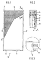
- It 1 shows a manufactured by means of profile bars Protective fence in a front view
- Figure 2 shows a section in the plane II-II of Figure 1
- Figure 3 the attachment of two Profile bars in a partially sectioned side view corresponding to the detail X of Figure 1
- Figures 4 to 6 cross sections through different profile bars
- Figures 7 to 9 cross sections through different arrangements with profile bars.
- a flat element 10 is shown in FIG serves as part of a protective fence, like him known, for example, for barriers in production halls is to gain access to certain areas prevent.
- the element 10 has the simplest case shown a rectangular frame 11 with two Longitudinal bars 12 and two transverse bars 13 connected thereto.
- the aluminum extrusion process Longitudinal bars 12 and the cross bars 13 each have one different length, otherwise they are identical educated.
- connection of the longitudinal rods 12 with the Cross bars 13 are made in each of the corners by means of a Connection element, in the example shown by means of one screw 14 each with its screw head in an undercut arranged on a side surface first longitudinal groove 15 of one of the longitudinal rods 12 or transverse rods 13 engages, and that in the face of a continuous Longitudinal bore 16 of the longitudinal bar 12 or transverse bar 13 can be screwed in (FIGS. 2 and 3).
- a protective grille 18 is arranged within the frame 11. Instead of the protective grid 18, however, there is also another one Element, for example a plexiglass pane conceivable.
- the Protective grille 18 has a thickness d which, because of the wires of the protective grid 18 corrugated and interwoven or are welded, is larger than the actual one Wire strength.
- the one in Cross section in approximately square longitudinal rod 12 or crossbar 13 has two opposite one another Side surfaces 19, 20 each have an undercut longitudinal groove, one of which is the already mentioned first longitudinal groove 15, and the other is referred to as the second longitudinal groove 21.
- the two longitudinal grooves 15, 21 either serve as Attachment possibility for the screw 14, or / and Attach additional elements, such as Warning boards that are simply inserted into the longitudinal groove 15, 21 and held there by clamping action.
- the middle section 22 is by means of four webs 23, which are diagonals of the Middle section 22 are located with the rest Profile cross-section connected.
- the receptacle 25 has two boundary walls 26, 27, of which the a boundary wall 26 a leg and at the same time one Forms side wall of the longitudinal bar 12 or cross bar 13.
- the other boundary wall 27 is on the one hand with two webs 23 connected to the central section 22, and forms on the other hand, part of the boundary walls of the longitudinal grooves 15, 21 out.
- Inner width B at least in a certain section is less than the thickness d of the protective grid 18.
- the bottom 28 of the receptacle 25, which is also part of the Side surface 19 of the longitudinal bar 12 or transverse bar 13, advantageously designed such that during insertion of the protective grille 18 in the receptacle 25 a certain elastic expansion through a corresponding wall thickness or training in the transition area 32 to the Boundary wall 26 of the receptacle 25 is made possible. Thereby a safe clamping of the protective grille 18 in the Realize recording 25.
- the longitudinal bar 12 or transverse bar shown in Figure 4 13 can be modified so that on one or two side surfaces 19, 20 on which the longitudinal grooves 15, 21st are arranged, additional longitudinal grooves are formed, those for clamping additional parts, or for connecting serve with other staffs. It is also conceivable that the Elevations 30 on the boundary walls 26, 27 only in certain sections, or just one of the two Boundary walls 26, 27 are formed.
- the second embodiment shown in Figure 5 differs from the former in particular in that two opposing receptacles 25a are provided.
- the depth of a such receptacle 25a now only in about half is the width of a side wall.
- an intermediate web 31 is provided, the two Separates recordings 25a.
- the one in FIG Profile bar 12a, 13a shown is in particular for horizontal or vertical division of the frame 11 used.
- a profile bar 12c, 13c can additionally 25c the recording to the clamping function by arranging one or bilateral, small lateral grooves 35 in the Boundary walls 26, 27 seal the protective grille 18th by means of rubber seals inserted in it.
- the recordings 25, 25a and 25c with the grooves 15, 21 corresponding to FIGS. 7 to 9 can functionally interact by using thinner Surfaces 36 or protective grilles with additional ones in the groove 15, 21 or the receptacle 25, 25a and 25c Clamping elements or clamping and sealing profiles 37 to 40 be provided. This results in variable applications of the Profile bar also in clean room technology.
Landscapes
- Engineering & Computer Science (AREA)
- Architecture (AREA)
- Civil Engineering (AREA)
- Structural Engineering (AREA)
- Fencing (AREA)
- Connection Of Plates (AREA)
Description
Claims (9)
- Bausatz aus wenigstens einem flächigen Element (18) und einem Profilstab (12, 13; 12a, 13a; 12c, 13c) mit wenigstens einer Aufnahme zur Befestigung des wenigstens einen flächigen Elements (18), insbesondere einer Platte oder eines gitterförmigen Zaunes, wobei die Aufnahme (25; 25a; 25c) als U-förmige Längsnut mit Begrenzungswänden (26, 27) und einer Bodenwand (28) ausgebildet ist, wobei die Breite (B) der Aufnahme (25; 25a; 25c) zumindest teilweise geringer als die Dicke (d) des flächigen Elements (18) ist, so daß das flächige Element (18) durch Klemmen in der Aufnahme (25; 25a; 25c) fixierbar ist,
wobei an wenigstens einer der Seitenflächen (19, 20) der Profilstabs (12, 13, 12a, 13a; 12c, 13c) wenigstens eine zweite Längsnut (15, 21) angeordnet ist, die als hinterschnittene Längsnut (15, 21) ausgebildet ist,
dadurch gekennzeichnet, daß die Begrenzungswände (26, 27) der Aufnahme (25; 25a; 25c) Sägezahnförmige Erhebungen (30) aufweisen, die dazu geeignet sind, beim Herausziehen des flächigen Elements (18) aus der Aufnahme (25) als Widerhaken für das flächige Element (18) zu wirken. - Profilstab nach Anspruch 1, dadurch gekennzeichnet, daß die zweite Längsnut (15, 21) eine geringere Nuttiefe aufweist als die Aufnahme (25; 25a; 25c).
- Profilstab nach einem der Ansprüche 1 oder 2, dadurch gekennzeichnet, daß der Profilstab (12, 13; 12a, 13a; 12c, 13c) eine Längsbohrung (16) zur stirnseitigen Befestigung des Profilstabs (12, 13; 12a, 13a; 12c, 13c) mit einem Verbindungselement (14) aufweist.
- Profilstab nach einem der Ansprüche 1 bis 3, dadurch gekennzeichnet, daß die eine Begrenzungswand (26) der Aufnahme (25; 25a) einen Schenkel ausbildet, der gleichzeitig zumindest Teil einer Seitenwand des Profilstabes (12, 13; 12a, 13a; 12c, 13c) ist.
- Profilstab nach Anspruch 4, dadurch gekennzeichnet, daß der Boden (28) der Aufnahme (25) Teil einer zweiten Seitenwand des Profilstabes (12, 13; 12c, 13c) ist.
- Profilstab nach einem der Ansprüche 1 bis 5, dadurch gekennzeichnet, daß die Aufnahme (25; 25a; 25c) einen federnden Bereich (32) zur Beeinflussung der Klemmwirkung aufweisen.
- Profilstab nach einem der Ansprüche 1 bis 6, dadurch gekennzeichnet, daß die Aufnahme (25; 25a; 25c) Einführschrägen (33) für das flächige Element (18) haben.
- Profilstab nach einem der Ansprüche 1 bis 7, dadurch gekennzeichnet, daß die Aufnahmen (25c) zusätzliche Hinterschnitte (34) oder Längsnuten (35) aufweisen.
- Profilstab nach einem der Ansprüche 1 bis 8, dadurch gekennzeichnet, daß zwei einander gegenüberliegende Aufnahmen (25a) vorgesehen sind, die voneiander durch einen Zwischensteg (31) getrennt sind.
Applications Claiming Priority (2)
| Application Number | Priority Date | Filing Date | Title |
|---|---|---|---|
| DE19751167A DE19751167C1 (de) | 1997-11-19 | 1997-11-19 | Profilstab |
| DE19751167 | 1997-11-19 |
Publications (3)
| Publication Number | Publication Date |
|---|---|
| EP0918121A1 EP0918121A1 (de) | 1999-05-26 |
| EP0918121B1 true EP0918121B1 (de) | 2003-08-20 |
| EP0918121B2 EP0918121B2 (de) | 2006-07-26 |
Family
ID=7849142
Family Applications (1)
| Application Number | Title | Priority Date | Filing Date |
|---|---|---|---|
| EP98119440A Expired - Lifetime EP0918121B2 (de) | 1997-11-19 | 1998-10-15 | Bausatz aus mindestens einem flächigem Element und einem Profilstab |
Country Status (3)
| Country | Link |
|---|---|
| US (1) | US6283456B1 (de) |
| EP (1) | EP0918121B2 (de) |
| DE (2) | DE19751167C1 (de) |
Cited By (1)
| Publication number | Priority date | Publication date | Assignee | Title |
|---|---|---|---|---|
| CN104895402A (zh) * | 2015-04-13 | 2015-09-09 | 张家港固耐特围栏系统有限公司 | 防护围栏立柱 |
Families Citing this family (38)
| Publication number | Priority date | Publication date | Assignee | Title |
|---|---|---|---|---|
| GB2355023A (en) * | 1999-08-28 | 2001-04-11 | Evalast Fencing Systems Ltd | A frame element for a fence panel |
| DE19943602B4 (de) * | 1999-09-11 | 2005-07-21 | Robert Bosch Gmbh | Federelement |
| FR2799771B1 (fr) * | 1999-10-19 | 2001-11-30 | Gunnebo Troax Ab | Panneau grillage de protection |
| AT408561B (de) * | 2000-03-20 | 2002-01-25 | Lenz Bernhard | Schutzzaun |
| US20020116890A1 (en) * | 2001-02-27 | 2002-08-29 | Eco-Block | Corner panel of a form system |
| DE10123906A1 (de) * | 2001-05-17 | 2002-11-21 | Hilti Ag | Doppel-Schienenprofil |
| DE10145899A1 (de) * | 2001-09-18 | 2003-04-03 | F I T Fertigungs Und Ind Techn | Profilstab und aus mehreren Profilstäben gebildeter Rahmen |
| DE10146517C1 (de) * | 2001-09-21 | 2003-03-27 | Siemens Ag | Stabförmiges Systemprofil zur baukastenartigen Gestaltung von Schutzeinrichtungen |
| US6669526B2 (en) | 2002-03-26 | 2003-12-30 | Mattel, Inc. | Construction toy set having low insertion force connecting bodies |
| US20030186616A1 (en) * | 2002-03-26 | 2003-10-02 | Manville Richard B. | Construction toy set having low insertion force connecting bodies |
| DE10251489B4 (de) * | 2002-11-04 | 2007-11-15 | H.F. Finke Gmbh & Co. | Zaunpfostensystem |
| US7680648B2 (en) | 2004-09-30 | 2010-03-16 | Google Inc. | Methods and systems for improving text segmentation |
| US20060113517A1 (en) * | 2004-11-30 | 2006-06-01 | Royal Group Technologies Limited | Modular fencing system and method for constructing same |
| US20060130414A1 (en) * | 2004-12-18 | 2006-06-22 | Mirco Walther | Spacer for mounting a deck ledger board to a building surface |
| USD567397S1 (en) * | 2005-11-11 | 2008-04-22 | Uchida Yoko Co., Ltd | Beam |
| AU2005242183B2 (en) * | 2005-12-09 | 2011-12-22 | Iph International Pty Ltd | Fencing system and method |
| US20080179577A1 (en) * | 2006-12-18 | 2008-07-31 | Neusch Innovations, Lp | Fence System |
| GB0813130D0 (en) * | 2008-07-17 | 2008-08-27 | Steelhoard Ltd | Fencing |
| DE102009053865B4 (de) * | 2009-11-20 | 2013-04-04 | Welser Profile Gmbh | Zaunpfostenanordnung mit einem kaltumgeformten Metallprofil |
| DE102010039838A1 (de) * | 2010-08-26 | 2012-03-01 | Bb-Stanz- Und Umformtechnik Gmbh | Profilschiene für Haltebügel |
| US8763303B2 (en) * | 2011-04-04 | 2014-07-01 | Curb Allure LLC | Tree guard |
| US8955250B2 (en) | 2011-04-04 | 2015-02-17 | Curb Allure LLC | Breakaway bracket for use with modular tree guard |
| WO2012142645A1 (en) | 2011-05-09 | 2012-10-26 | Blh Safety Solutions Pty Ltd | Safety barricade system |
| US8636266B2 (en) * | 2011-08-03 | 2014-01-28 | Bart's Ltd. | Safety barricading system |
| KR101402080B1 (ko) * | 2012-01-25 | 2014-06-02 | 주식회사 린노 | 시트 고정용 프레임 |
| AU2013373710B2 (en) * | 2013-01-21 | 2017-09-07 | Aluminios La Serena, S.A. | Panel securing mechanism for a game court enclosure |
| CN103615647A (zh) * | 2013-11-29 | 2014-03-05 | 苏州市亿达净化实验室设备有限公司 | 用作框架组装的铝型材 |
| CN104165265A (zh) * | 2014-07-04 | 2014-11-26 | 苏州琼派瑞特电子科技有限公司 | 一种横杆 |
| DE102015111477A1 (de) * | 2015-07-15 | 2017-01-19 | M. Braun Inertgas-Systeme Gmbh | Rahmenprofil, Wandelement und Rahmengestell für eine Reingaskabine |
| USD880726S1 (en) * | 2018-03-21 | 2020-04-07 | Long Xiang Shen | Fence screen |
| JP7294345B2 (ja) | 2018-09-28 | 2023-06-20 | 日本ゼオン株式会社 | 樹脂組成物及びその成形体 |
| US10889985B2 (en) * | 2020-06-05 | 2021-01-12 | Nan Ya Plastics Corporation | Divider assembly |
| DE102021201483A1 (de) | 2021-02-17 | 2022-08-18 | Robert Bosch Gesellschaft mit beschränkter Haftung | Verbinder zur Befestigung eines Flächenelements an einer hinterschnittenen T-Nut |
| US12618260B1 (en) * | 2021-12-06 | 2026-05-05 | Larry Bergsma | Fence and gate systems and methods for use |
| USD1040375S1 (en) * | 2022-09-14 | 2024-08-27 | Brunkeberg Systems Ab | Section of building material |
| DE102022212544A1 (de) * | 2022-11-24 | 2024-05-29 | Robert Bosch Gesellschaft mit beschränkter Haftung | Trennwand mit zweiteiligen Säulen |
| US12509907B2 (en) * | 2023-09-19 | 2025-12-30 | Xia Shin International Co., Ltd. | Vertical post structure of fence |
| USD1093654S1 (en) * | 2025-01-07 | 2025-09-16 | Shenzhen Weimeiwu Home Decoration Co., Ltd. | Glass railing spigot |
Family Cites Families (27)
| Publication number | Priority date | Publication date | Assignee | Title |
|---|---|---|---|---|
| US1567446A (en) * | 1924-11-28 | 1925-12-29 | Mcclure Edward | Wire-mesh guard and the like |
| US3385567A (en) * | 1965-11-05 | 1968-05-28 | Reynolds Metals Co | Railing constructions and parts therefor or the like |
| BE709995A (de) * | 1968-01-29 | 1968-05-30 | ||
| DE2011657A1 (de) * | 1970-03-12 | 1970-10-08 | Gebr. Kaufmann , Drahtwarenfabrik, 7239 Aistaig | Randeinfassung für Drahtgitterzäune |
| US3973756A (en) * | 1972-01-24 | 1976-08-10 | Cegedur Gp | Railing and method of assembly |
| US3770245A (en) * | 1972-02-07 | 1973-11-06 | Rebco West Inc | Interlocking frame construction |
| GB1536546A (en) * | 1975-05-02 | 1978-12-20 | Midland Extrusions Ltd | Fencing systems |
| US4110942A (en) * | 1977-05-06 | 1978-09-05 | Slocomb Jr Leon F | Window frame manufacture |
| US4132390A (en) * | 1977-07-15 | 1979-01-02 | Anchor Post Products, Inc. | Gate and panel system |
| US4333284A (en) * | 1979-01-08 | 1982-06-08 | Donel Corporation | Extrusion and building structures |
| DE7906346U1 (de) * | 1979-03-06 | 1979-07-12 | Gerhard Ebeling Drahtzaunfabrik Ohg, 1000 Berlin | Krippgitter |
| JPS60500678A (ja) * | 1983-03-08 | 1985-05-09 | コスタンザ ピ−テイ−ワイ リミテツド | フェンス等の構造 |
| DE3438365C2 (de) | 1984-10-19 | 1994-02-24 | Schober Kg Raumtech | Profilstange zum Festklemmen von Platten, insbesondere von Glasplatten für Schauvitrinen, Verkaufstheken, Messemobiliar o.dgl. |
| US4712942A (en) * | 1986-09-22 | 1987-12-15 | Brown Robert K | Joint maker |
| DE8632787U1 (de) * | 1986-12-06 | 1987-02-05 | REHAU AG + Co, 8673 Rehau | Profilstreifen zum Einfassen von Fensterscheiben |
| DE3900411C2 (de) * | 1989-01-09 | 2002-08-22 | Peter Hauser | Stranggußprofil |
| DE4005160A1 (de) * | 1990-02-17 | 1991-08-22 | Aderhold Hermann Adronit Werk | Gitterzaun |
| DE9100099U1 (de) * | 1991-01-07 | 1991-06-13 | Bahr, Frank, 4952 Porta Westfalica | Durch Schrauben mit einem Profilstab verbundener Tragstab |
| DE9100699U1 (de) * | 1991-01-22 | 1991-05-16 | Wallau, Helmut, 5464 Buchholz | Knotenelement |
| DE9103993U1 (de) * | 1991-04-03 | 1991-10-31 | Papst, Hans Dieter, Dipl.-Ing., 7742 St Georgen | Schutzgitter mit fester Umrahmung |
| DE4208720A1 (de) * | 1992-03-18 | 1993-09-23 | Helmut Walter Leicht | Profil mit kraftschluessiger aufnahme |
| DE4307492C2 (de) * | 1993-03-10 | 1996-06-13 | Hans Victor Schoenfeld | Hohlprofil |
| DE9403048U1 (de) * | 1994-02-24 | 1994-04-28 | RK Rose + Krieger GmbH & Co. KG Verbindungs- und Positioniersysteme, 32423 Minden | Profilrohr mit Klemmnuten |
| US5551205A (en) * | 1994-08-03 | 1996-09-03 | Kidder; Roger | Mounting frame construction for a sheet of plastic, screen guard or the like |
| US5647181A (en) * | 1994-10-11 | 1997-07-15 | Hunts; Larry David | Construction system and method for connecting rigid sheet-like panels together into doll houses, play houses, utility sheds and other structures |
| DE29701455U1 (de) | 1997-01-29 | 1997-04-24 | Seidl + Mayer Lochbleche GmbH, 80807 München | Mit einem Einfaßprofil randseitig umgebenes Drahtgitter |
| US6003279A (en) * | 1998-08-13 | 1999-12-21 | Schneider; Dale P. | Sunroom enclosure |
-
1997
- 1997-11-19 DE DE19751167A patent/DE19751167C1/de not_active Expired - Lifetime
-
1998
- 1998-10-15 EP EP98119440A patent/EP0918121B2/de not_active Expired - Lifetime
- 1998-10-15 DE DE59809334T patent/DE59809334D1/de not_active Expired - Lifetime
- 1998-11-19 US US09/196,287 patent/US6283456B1/en not_active Expired - Fee Related
Cited By (1)
| Publication number | Priority date | Publication date | Assignee | Title |
|---|---|---|---|---|
| CN104895402A (zh) * | 2015-04-13 | 2015-09-09 | 张家港固耐特围栏系统有限公司 | 防护围栏立柱 |
Also Published As
| Publication number | Publication date |
|---|---|
| EP0918121A1 (de) | 1999-05-26 |
| US6283456B1 (en) | 2001-09-04 |
| DE59809334D1 (de) | 2003-09-25 |
| EP0918121B2 (de) | 2006-07-26 |
| DE19751167C1 (de) | 1999-06-24 |
Similar Documents
| Publication | Publication Date | Title |
|---|---|---|
| EP0918121B2 (de) | Bausatz aus mindestens einem flächigem Element und einem Profilstab | |
| EP0683287B1 (de) | Profilschiene zur Befestigung flächiger Gegenstände | |
| DE2537106A1 (de) | Fuehrungs- und halteeinrichtung fuer leiterplatten mit gedruckten schaltungen | |
| EP0136431A2 (de) | Konstruktion aus Profilstäben | |
| EP1921722A1 (de) | Schaltschrank für eine elektrische Installationsverteilung | |
| DE202010004714U1 (de) | Photovoltaische Anlage aus Dünnschichtsolarmodulen | |
| EP0801202B1 (de) | Verbindungsvorrichtung für eine Sprossenkreuzkonstuktion | |
| EP0315936B1 (de) | Klotzteil zum Festsetzen von Glasscheiben od. dgl. | |
| AT516721B1 (de) | Geländer und Verfahren zur Herstellung eines Geländers | |
| DE202004021527U1 (de) | Verbinder für Doppelfenster-Rahmenprofile | |
| EP0952778B1 (de) | Gestell zur aufnahme eines zu tragenden teiles | |
| DE29720488U1 (de) | Profilstab | |
| DE102012102243B4 (de) | Rahmenbausatz, Solarmodulvorrichtung und Solarmodul-Montageverfahren | |
| EP1083340B1 (de) | Federelement | |
| EP0687790A1 (de) | Linearverbinder für hohle Abstandsprofile eines Mehrscheibenisolierglases | |
| DE102005058386A1 (de) | Pfosten-Riegel-Verbindung | |
| CH688907A5 (de) | Baugruppentraeger mit Profilleisten und mit Deckplatten. | |
| DE4036859C2 (de) | Trennwand | |
| DE10043443B4 (de) | Fenster- oder Türrahmen mit einem Verbinder | |
| DE10043444B4 (de) | Fenster- oder Türrahmen mit einem verschraubten Verbinder | |
| DE102004055556B4 (de) | Verbindungselement für Profile | |
| DE8913616U1 (de) | Abstandhalterahmen für Isolierverglasungen | |
| DE202004017856U1 (de) | Verbindungselement für Profile | |
| DE4421107A1 (de) | Vorrichtung zur Verbindung von Profilleisten | |
| DE29900401U1 (de) | Befestigungskonstruktion für mit Kanälen versehenen Fassadenplatten |
Legal Events
| Date | Code | Title | Description |
|---|---|---|---|
| PUAI | Public reference made under article 153(3) epc to a published international application that has entered the european phase |
Free format text: ORIGINAL CODE: 0009012 |
|
| AK | Designated contracting states |
Kind code of ref document: A1 Designated state(s): CH DE FR GB IT LI SE |
|
| AX | Request for extension of the european patent |
Free format text: AL;LT;LV;MK;RO;SI |
|
| 17P | Request for examination filed |
Effective date: 19991126 |
|
| AKX | Designation fees paid |
Free format text: CH DE FR GB IT LI SE |
|
| 17Q | First examination report despatched |
Effective date: 20010215 |
|
| GRAH | Despatch of communication of intention to grant a patent |
Free format text: ORIGINAL CODE: EPIDOS IGRA |
|
| RTI1 | Title (correction) |
Free format text: KIT COMPRISING AT LEAST A PLAIN ELEMENT AND A PROFILED BAR |
|
| GRAS | Grant fee paid |
Free format text: ORIGINAL CODE: EPIDOSNIGR3 |
|
| GRAA | (expected) grant |
Free format text: ORIGINAL CODE: 0009210 |
|
| RIN1 | Information on inventor provided before grant (corrected) |
Inventor name: BREITENBUECHER, ARMIN Inventor name: KLEMD, OLAF Inventor name: KOBAN, JOHANNES Inventor name: WALTHER, JOERG Inventor name: BENZ, ALBRECHT |
|
| AK | Designated contracting states |
Designated state(s): CH DE FR GB IT LI SE |
|
| REG | Reference to a national code |
Ref country code: GB Ref legal event code: FG4D Free format text: NOT ENGLISH |
|
| REG | Reference to a national code |
Ref country code: CH Ref legal event code: EP |
|
| REG | Reference to a national code |
Ref country code: CH Ref legal event code: NV Representative=s name: SCINTILLA AG, DIREKTION |
|
| REF | Corresponds to: |
Ref document number: 59809334 Country of ref document: DE Date of ref document: 20030925 Kind code of ref document: P |
|
| REG | Reference to a national code |
Ref country code: SE Ref legal event code: TRGR |
|
| GBT | Gb: translation of ep patent filed (gb section 77(6)(a)/1977) | ||
| PLBQ | Unpublished change to opponent data |
Free format text: ORIGINAL CODE: EPIDOS OPPO |
|
| ET | Fr: translation filed | ||
| PLBI | Opposition filed |
Free format text: ORIGINAL CODE: 0009260 |
|
| PLAX | Notice of opposition and request to file observation + time limit sent |
Free format text: ORIGINAL CODE: EPIDOSNOBS2 |
|
| 26 | Opposition filed |
Opponent name: BAUER PROFILTECHNIK GMBH Effective date: 20040519 |
|
| PLAX | Notice of opposition and request to file observation + time limit sent |
Free format text: ORIGINAL CODE: EPIDOSNOBS2 |
|
| PLBB | Reply of patent proprietor to notice(s) of opposition received |
Free format text: ORIGINAL CODE: EPIDOSNOBS3 |
|
| PUAH | Patent maintained in amended form |
Free format text: ORIGINAL CODE: 0009272 |
|
| STAA | Information on the status of an ep patent application or granted ep patent |
Free format text: STATUS: PATENT MAINTAINED AS AMENDED |
|
| 27A | Patent maintained in amended form |
Effective date: 20060726 |
|
| AK | Designated contracting states |
Kind code of ref document: B2 Designated state(s): CH DE FR GB IT LI SE |
|
| REG | Reference to a national code |
Ref country code: CH Ref legal event code: AEN Free format text: AUFRECHTERHALTUNG DES PATENTES IN GEAENDERTER FORM |
|
| REG | Reference to a national code |
Ref country code: SE Ref legal event code: RPEO |
|
| GBTA | Gb: translation of amended ep patent filed (gb section 77(6)(b)/1977) | ||
| ET3 | Fr: translation filed ** decision concerning opposition | ||
| PGFP | Annual fee paid to national office [announced via postgrant information from national office to epo] |
Ref country code: IT Payment date: 20101023 Year of fee payment: 13 Ref country code: GB Payment date: 20101021 Year of fee payment: 13 |
|
| PGFP | Annual fee paid to national office [announced via postgrant information from national office to epo] |
Ref country code: SE Payment date: 20111021 Year of fee payment: 14 Ref country code: CH Payment date: 20111025 Year of fee payment: 14 Ref country code: FR Payment date: 20111103 Year of fee payment: 14 |
|
| PGFP | Annual fee paid to national office [announced via postgrant information from national office to epo] |
Ref country code: DE Payment date: 20111205 Year of fee payment: 14 |
|
| REG | Reference to a national code |
Ref country code: CH Ref legal event code: PL |
|
| GBPC | Gb: european patent ceased through non-payment of renewal fee |
Effective date: 20121015 |
|
| REG | Reference to a national code |
Ref country code: FR Ref legal event code: ST Effective date: 20130628 |
|
| PG25 | Lapsed in a contracting state [announced via postgrant information from national office to epo] |
Ref country code: LI Free format text: LAPSE BECAUSE OF NON-PAYMENT OF DUE FEES Effective date: 20121031 Ref country code: DE Free format text: LAPSE BECAUSE OF NON-PAYMENT OF DUE FEES Effective date: 20130501 Ref country code: SE Free format text: LAPSE BECAUSE OF NON-PAYMENT OF DUE FEES Effective date: 20121016 Ref country code: CH Free format text: LAPSE BECAUSE OF NON-PAYMENT OF DUE FEES Effective date: 20121031 Ref country code: GB Free format text: LAPSE BECAUSE OF NON-PAYMENT OF DUE FEES Effective date: 20121015 |
|
| REG | Reference to a national code |
Ref country code: DE Ref legal event code: R119 Ref document number: 59809334 Country of ref document: DE Effective date: 20130501 |
|
| PG25 | Lapsed in a contracting state [announced via postgrant information from national office to epo] |
Ref country code: FR Free format text: LAPSE BECAUSE OF NON-PAYMENT OF DUE FEES Effective date: 20121031 Ref country code: IT Free format text: LAPSE BECAUSE OF NON-PAYMENT OF DUE FEES Effective date: 20121015 |