EP0907539B1 - Hydraulische bremsanlage für kraftfahrzeuge - Google Patents
Hydraulische bremsanlage für kraftfahrzeuge Download PDFInfo
- Publication number
- EP0907539B1 EP0907539B1 EP97929271A EP97929271A EP0907539B1 EP 0907539 B1 EP0907539 B1 EP 0907539B1 EP 97929271 A EP97929271 A EP 97929271A EP 97929271 A EP97929271 A EP 97929271A EP 0907539 B1 EP0907539 B1 EP 0907539B1
- Authority
- EP
- European Patent Office
- Prior art keywords
- brake
- pressure
- hydraulic
- warning device
- brake system
- Prior art date
- Legal status (The legal status is an assumption and is not a legal conclusion. Google has not performed a legal analysis and makes no representation as to the accuracy of the status listed.)
- Expired - Lifetime
Links
- 239000012530 fluid Substances 0.000 claims description 16
- 238000000034 method Methods 0.000 claims description 8
- 238000010586 diagram Methods 0.000 description 3
- 238000002474 experimental method Methods 0.000 description 2
- 239000003550 marker Substances 0.000 description 2
- 230000006835 compression Effects 0.000 description 1
- 238000007906 compression Methods 0.000 description 1
- 238000011161 development Methods 0.000 description 1
- 238000011156 evaluation Methods 0.000 description 1
- 238000007689 inspection Methods 0.000 description 1
- 239000007788 liquid Substances 0.000 description 1
- 238000012423 maintenance Methods 0.000 description 1
Images
Classifications
-
- B—PERFORMING OPERATIONS; TRANSPORTING
- B60—VEHICLES IN GENERAL
- B60T—VEHICLE BRAKE CONTROL SYSTEMS OR PARTS THEREOF; BRAKE CONTROL SYSTEMS OR PARTS THEREOF, IN GENERAL; ARRANGEMENT OF BRAKING ELEMENTS ON VEHICLES IN GENERAL; PORTABLE DEVICES FOR PREVENTING UNWANTED MOVEMENT OF VEHICLES; VEHICLE MODIFICATIONS TO FACILITATE COOLING OF BRAKES
- B60T17/00—Component parts, details, or accessories of power brake systems not covered by groups B60T8/00, B60T13/00 or B60T15/00, or presenting other characteristic features
- B60T17/18—Safety devices; Monitoring
- B60T17/22—Devices for monitoring or checking brake systems; Signal devices
- B60T17/221—Procedure or apparatus for checking or keeping in a correct functioning condition of brake systems
-
- B—PERFORMING OPERATIONS; TRANSPORTING
- B60—VEHICLES IN GENERAL
- B60T—VEHICLE BRAKE CONTROL SYSTEMS OR PARTS THEREOF; BRAKE CONTROL SYSTEMS OR PARTS THEREOF, IN GENERAL; ARRANGEMENT OF BRAKING ELEMENTS ON VEHICLES IN GENERAL; PORTABLE DEVICES FOR PREVENTING UNWANTED MOVEMENT OF VEHICLES; VEHICLE MODIFICATIONS TO FACILITATE COOLING OF BRAKES
- B60T8/00—Arrangements for adjusting wheel-braking force to meet varying vehicular or ground-surface conditions, e.g. limiting or varying distribution of braking force
- B60T8/32—Arrangements for adjusting wheel-braking force to meet varying vehicular or ground-surface conditions, e.g. limiting or varying distribution of braking force responsive to a speed condition, e.g. acceleration or deceleration
- B60T8/88—Arrangements for adjusting wheel-braking force to meet varying vehicular or ground-surface conditions, e.g. limiting or varying distribution of braking force responsive to a speed condition, e.g. acceleration or deceleration with failure responsive means, i.e. means for detecting and indicating faulty operation of the speed responsive control means
- B60T8/92—Arrangements for adjusting wheel-braking force to meet varying vehicular or ground-surface conditions, e.g. limiting or varying distribution of braking force responsive to a speed condition, e.g. acceleration or deceleration with failure responsive means, i.e. means for detecting and indicating faulty operation of the speed responsive control means automatically taking corrective action
- B60T8/94—Arrangements for adjusting wheel-braking force to meet varying vehicular or ground-surface conditions, e.g. limiting or varying distribution of braking force responsive to a speed condition, e.g. acceleration or deceleration with failure responsive means, i.e. means for detecting and indicating faulty operation of the speed responsive control means automatically taking corrective action on a fluid pressure regulator
Definitions
- the present invention relates to a hydraulic brake system for motor vehicles according to the preamble of claim 1 and a method for evaluating the brake fluid pressure at various points in such a facility.
- Such a hydraulic brake system for motor vehicles is known for example from DE 44 38 927.
- This Document discloses a brake system, which besides one Brake slip control also a traction control system or can make a different driving stability regulation.
- the fluid pressures are particularly important for slip control at various points in the brake lines Pressure transducer measured and evaluated in a facility, for example to switch a pump on or off.
- DE 33 47 819 is a brake light switch for Motor vehicles known.
- the brake lights become one Motor vehicle via a mechanical arranged on the pedal bracket Switch operated.
- Such a switch is relative heavy, expensive and must be connected to the pedal bracket become.
- DE 40 29 793 A1 is a hydraulic Vehicle brake system known in the pressure sensors for warning of a pressure drop in the system are.
- the present invention is therefore based on the object a hydraulic brake system of the type described above to propose where the brake fluid pressure related Warning devices are inexpensive and are light in weight.
- the pressure warning device executed as a display for the failure of a brake circuit.
- This electronic circuit failure indicator takes over the tasks previously performed by the hydraulic differential pressure warning device have been carried out.
- a level marker and the level of the brake fluid in the built-in Condition can be checked without opening the container closure is according to the invention in the hydraulic brake system on a container warning device designed with a float to be dispensed with. About the swimmer the level of the brake fluid is usually recorded and a warning device if the liquid level is too low actuated. If the pressure warning device according to the invention is designed as a circular failure indicator, there is no such indicator Warning device. Since the circuit failure, as described later, The brake fluid reservoir must only be signaled when the brake pedal is pressed be visible so that the brake fluid level drops optically, for example with a routine Maintenance of the motor vehicle can be performed.
- the pressure warning device is integrated in an on-board computer, which is already present in many new cars these days.
- those emanating from the pressure sensors Signals in at least one electronic pressure warning device recorded and processed.
- the signals from the pressure sensors are preferred evaluated separately, but they can also be recorded together and processed.
- An indication of a brake circuit failure occurs when the brake is actuated Pedal device according to the invention when the output signal at least one pressure sensor a predetermined one Falls below the setpoint.
- Such setpoints can for example depending on the pedal actuation force can be easily determined via experiments.
- the circuit failure display is preferably carried out when the Difference of signals from at least two in different Circles arranged pressure sensors a predetermined Setpoint exceeds.
- the brake lights of the motor vehicle can also be turned on when the signal is at least one Pressure sensor exceeds a predetermined setpoint.
- This setpoint can be analogous to the above, for example also depending on the vehicle type.
- the brake lights of the motor vehicle are switched off analogously, if the signals from the pressure sensors are too specified and correspondingly lower setpoint below.
- the evaluation of those originating from the pressure sensors Signals are preferably carried out in an on-board computer.
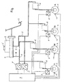
- FIG. 1 In this circuit diagram is the hydraulic one according to the invention Brake system for motor vehicles shown in a roughly simplified manner.
- the plan shows a master cylinder 1 which is attached to a caster or Reservoir 2 for brake fluid is connected, which is usually closed by a screwable cover 2 ' is.
- the master cylinder 1 is operated by a pedal device 3 operated, this directly or indirectly via a brake booster, not shown here happen can.
- the hydraulic brake system has a primary and a secondary circuit (I, II), with a diagonal division in the figure is shown, i.e. the wheel brakes 4 in front right (VR) and rear left (HL) and wheel brakes 4 rear right (HR) and front left (VL) are over each other Brake fluid lines 5 connected.
- the invention can also be a hydraulic one Act the brake system with a different division.
- Components 6, which are, for example, a Pump, valve or the like can only act as a black box shown.
- Pressure sensors 7, 8 available, with the help of the brake fluid pressures at different points in the respective brake circuits I, II recorded and converted into an electronic signal become. These signals are preferred in the invention pressure warning device 9 integrated in the on-board computer and processed there. If the pressure warning device 9 is trained in the on-board computer, there can also be other electronic ones Signals, for example from wheel sensors 10, are evaluated become.
- the pressure warning device 9 as a circuit failure indicator are preferably the electronic signals of the Compression voltage converter 7, which is particularly close to the Master cylinder 1 are attached, evaluated. exceeds the pressure difference in the brake circuits I, II a certain Value, this is done electronically by the pressure warning device 9 a signal, for example in the form of a warning lamp, to the driver of the motor vehicle.
- the signals of the pressure-voltage converter 7 can also be used individually be evaluated so that an error warning to the driver occurs when a single brake circuit I, II fails and that sensor 7 reports a signal that a predetermined, for example, falls below the target value determined in experiments.
- the present invention to a conventional container warning device that has a Float is activated when the brake fluid level falls below a minimum value in container 2, are waived.
- the circuit failure device 9 only reports the circuit failure a brake circuit I, II with the brake pedal 3 actuated, so while driving.
- the hold tank 2 according to the invention in an advantageous manner at least partially transparent, for example with a shop window or completely transparent formed and has a level marker, which can be designed as a max-min display.
- the fill level the brake fluid is in the installed state easy to check without opening the container closure 2 ', so that when refueling or some other inspection can be perceived from the outside.
- the brake lights one Motor vehicle be turned on or off. Switching on takes place when the signal of at least one pressure-voltage converter 7, 8 a setpoint which is in turn predetermined exceeds. If it falls below this setpoint again the brake lights switch off automatically. The brake lights can also be switched off, if the value falls below another setpoint, the lower one than this one is.
- the brake lights are over near the Wheel brakes 4 attached pressure-voltage converter 8 switched, because here the signal of an actual braking is the fastest is present. But it is also possible to use the brake lights to switch over the sensors 7 when a quick response to an actual actuation of the brake pedal 3 by the Driver is desired.
Landscapes
- Engineering & Computer Science (AREA)
- Transportation (AREA)
- Mechanical Engineering (AREA)
- Physics & Mathematics (AREA)
- Fluid Mechanics (AREA)
- Valves And Accessory Devices For Braking Systems (AREA)
Description
- Fig.,
- die einen vereinfachten Schaltplan der hydraulischen Bremsanlage gemäß der vorliegenden Erfindung zeigt.
- 1
- Hauptzylinder
- 2
- Nachlaufbehälter
- 2'
- Behälterverschluß
- 3
- Pedaleinrichtung
- 4
- Radbremse
- 5
- Bremsleitung
- 6
- Hydraulikbauteil
- 7
- Druckspannungswandler
- 8
- Druckspannungswandler
- 9
- Druckwarneinrichtung bzw. Bordcomputer
- I
- Primärbremskreis
- II
- Sekundärbremskreis
Claims (11)
- Hydraulische Bremsanlage für Kraftfahrzeuge mit einem Hauptzylinder (1), der an einen Nachlaufbehälter (2) für Bremsflüssigkeit angeschlossen ist und über eine Pedaleinrichtung (3) betätigt wird, mit mindestens zwei Radbremsen (4), die über Bremsleitungen (5) und hydraulische Bauteile (6) mit dem Hauptzylinder (1) in Verbindung stehen und durch diesen über verschiedene Bremskreise (I, II) betätigt werden, und mit mindestens einem Drucksensor (7,8), dadurch gekennzeichnet, dass in der hydraulischen Bremsanlage zumindest eine elektronische Druckwarneinrichtung (9) vorgesehen ist und dass die Druckwarneinrichtung (9) ferner als Bremslichtbetätigungseinrichtung vorgesehen ist.
- Hydraulische Bremsanlage nach Anspruch 1, dadurch gekennzeichnet, dass die Druckwarneinrichtung (9) als Anzeige für den Ausfall eines Bremskreises (I, II) ausgeführt ist.
- Hydraulische Bremsanlage nach Anspruch 2, dadurch gekennzeichnet, dass der Nachlaufbehälter (2) zumindest teilweise transparent ausgebildet ist, eine Füllstandsmarkierung aufweist und der Füllstand der Bremsflüssigkeit im eingebauten Zustand ohne Öffnen eines Behälterverschlusses (2') überprüfbar ist.
- Hydraulische Bremsanlage nach einem der vorhergehenden Ansprüche, dadurch gekennzeichnet, dass die Druckwarneinrichtung (9) in einem Bordcomputer (9) integriert ist.
- Verfahren zur Auswertung von Bremsflüssigkeitsdrücken in einer hydraulischen Bremsanlage für Kraftfahrzeuge, die einen Hauptzylinder (1), der an einen Nachlaufbehälter (2) für Bremsflüssigkeit angeschlossen ist und über eine Pedaleinrichtung (3) betätigt wird, mindestens zwei Radbremsen (4), die über Bremsleitungen (5) und hydraulische Bauteile (6) mit dem Hauptzylinder (1) in Verbindung stehen und durch diesen über verschiedene Bremskreise (I, II) betätigt werden, und mindestens einen Drucksensor (7,8) aufweist, dadurch gekennzeichnet, dass von dem Drucksensor (7,8) ausgehende Signale in zumindest einer elektronischen Druckwarneinrichtung (9) ausgewertet werden und dass die Druckwarneinrichtung (9) ferner als Bremslichtbetätigungseinrichtung vorgesehen ist.
- Verfahren nach Anspruch 5, dadurch gekennzeichnet, dass die Signale der Drucksensoren (7, 8) getrennt ausgewertet werden.
- Verfahren nach Anspruch 6, dadurch gekennzeichnet, dass bei betätigter Pedaleinrichtung (3) eine Anzeige für den Ausfall eines Bremskreises (I, II) erfolgt, wenn das Signal zumindest eines Drucksensors (7, 8) einen vorgegebenen Sollwert unterschreitet.
- Verfahren nach Anspruch 5 oder 6, dadurch gekennzeichnet, dass bei betätigter Pedaleinrichtung (3) eine Anzeige für den Kreisausfall erfolgt, wenn die Differenz der Signale von wenigstens zwei in verschiedenen Kreisen (I, II) angeordneten Drucksensoren (7, 8) einen vorgegebenen Sollwert überschreitet.
- Verfahren nach Anspruch 5 oder 6, dadurch gekennzeichnet, dass die Bremslichter des Kraftfahrzeuges eingeschaltet werden, wenn das Signal zumindest eines Drucksensors (7, 8) einen vorgegebenen Sollwert überschreitet.
- Verfahren nach Anspruch 5 oder 6, dadurch gekennzeichnet, dass die Bremslichter des Kraftfahrzeuges ausgeschaltet werden, wenn die Signale der Drucksensoren (7, 8) einen vorgegebenen Sollwert unterschreiten.
- Verfahren nach einem der Ansprüche 5 bis 10, dadurch gekennzeichnet, dass die Auswertung der von den Drucksensoren (7, 8) ausgehenden Signale in einem Bordcomputer (9) erfolgt.
Applications Claiming Priority (3)
| Application Number | Priority Date | Filing Date | Title |
|---|---|---|---|
| DE19626306A DE19626306A1 (de) | 1996-07-01 | 1996-07-01 | Hydraulische Bremsanlage für Kraftfahrzeuge |
| DE19626306 | 1996-07-01 | ||
| PCT/EP1997/003294 WO1998000326A1 (de) | 1996-07-01 | 1997-06-24 | Hydraulische bremsanlage für kraftfahrzeuge |
Publications (2)
| Publication Number | Publication Date |
|---|---|
| EP0907539A1 EP0907539A1 (de) | 1999-04-14 |
| EP0907539B1 true EP0907539B1 (de) | 2004-01-21 |
Family
ID=7798519
Family Applications (1)
| Application Number | Title | Priority Date | Filing Date |
|---|---|---|---|
| EP97929271A Expired - Lifetime EP0907539B1 (de) | 1996-07-01 | 1997-06-24 | Hydraulische bremsanlage für kraftfahrzeuge |
Country Status (3)
| Country | Link |
|---|---|
| EP (1) | EP0907539B1 (de) |
| DE (2) | DE19626306A1 (de) |
| WO (1) | WO1998000326A1 (de) |
Cited By (1)
| Publication number | Priority date | Publication date | Assignee | Title |
|---|---|---|---|---|
| CN101786450A (zh) * | 2010-02-26 | 2010-07-28 | 吉林大学 | 一种车辆制动管路压力监测预警系统 |
Families Citing this family (5)
| Publication number | Priority date | Publication date | Assignee | Title |
|---|---|---|---|---|
| DE19804077A1 (de) * | 1998-02-03 | 1999-08-12 | Uwe Rehwald | Bremsanlage für ein Fahrzeug |
| DE10018178A1 (de) * | 2000-04-12 | 2001-10-25 | Bayerische Motoren Werke Ag | Elektrisch gesteuertes, insbesondere elektromechanisches Bremssystem für ein Kraftfahrzeug |
| DE102008024661B4 (de) | 2008-05-21 | 2024-11-14 | Zf Cv Systems Hannover Gmbh | Verfahren zum Erkennen eines Kreisausfalls eines Fahrzeugbremssystems |
| DE102018202287A1 (de) * | 2018-02-15 | 2019-08-22 | Robert Bosch Gmbh | Elektrohydraulische Fremdkraft-Fahrzeugbremsanlage für ein autonom fahrendes Landfahrzeug |
| CN110936945B (zh) * | 2019-11-11 | 2021-03-09 | 南京航空航天大学 | 一种基于多传感器融合的盘式制动器自检测系统及方法 |
Family Cites Families (21)
| Publication number | Priority date | Publication date | Assignee | Title |
|---|---|---|---|---|
| DE1731875U (de) * | 1956-06-14 | 1956-10-11 | Gerhard Dinter | Bremsfluessigkeitsbehaelter fuer kraftfahrzeuge. |
| DE2316992C3 (de) * | 1969-12-10 | 1981-05-14 | Alfred Teves Gmbh, 6000 Frankfurt | Warnschalter für hydraulische Zweikreisbremsanlagen |
| US3827522A (en) * | 1973-08-10 | 1974-08-06 | Koehring Co | Fluid pressure actuated brake light switch |
| US4414630A (en) * | 1980-03-19 | 1983-11-08 | Lucas Industries Limited | Anti-skid vehicle braking systems |
| US4335167A (en) * | 1980-06-02 | 1982-06-15 | Edison International, Inc. | Brake fluid reservoir comprising polymethylpentene and 10-20% glass fibers |
| DE3137200A1 (de) * | 1981-09-18 | 1983-03-31 | Robert Bosch Gmbh, 7000 Stuttgart | Zweikreis-bremseinrichtung |
| EP0112194A1 (de) * | 1982-11-01 | 1984-06-27 | The Bendix Corporation | Warngerät für ein Fahrzeugbremssystem |
| DE3511579A1 (de) * | 1985-03-29 | 1986-10-02 | Robert Bosch Gmbh, 7000 Stuttgart | Verfahren und vorrichtung zur bremsdrucksteuerung bei fahrzeugbremsanlagen |
| DE3601914C2 (de) * | 1986-01-23 | 1996-05-15 | Teves Gmbh Alfred | Hydraulische Bremsanlage für Kraftfahrzeuge |
| DE3713662C2 (de) * | 1987-04-24 | 1996-02-29 | Teves Gmbh Alfred | Elektrohydraulische Vorrichtung zur kontinuierlichen Überwachung des Druckes in einer hydraulischen Kraftfahrzeug-Bremsanlage |
| DE3829949A1 (de) * | 1988-09-03 | 1990-03-15 | Daimler Benz Ag | Verfahren zum betrieb einer elektrischen druckmittel-betriebsbremseinrichtung und steuervorrichtung zur durchfuehrung des verfahrens |
| GB8905311D0 (en) | 1989-03-08 | 1989-04-19 | Lucas Ind Plc | Electronic braking system |
| DE3922947A1 (de) * | 1989-07-12 | 1991-01-17 | Bosch Gmbh Robert | Hydraulische fahrzeugbremsanlage |
| DE4029793C2 (de) | 1990-09-20 | 1999-05-06 | Bosch Gmbh Robert | Hydraulische Fahrzeugbremsanlage |
| DE4037662A1 (de) * | 1990-11-27 | 1992-06-04 | Bosch Gmbh Robert | Bremsanlage |
| DE4132767C2 (de) * | 1991-10-02 | 1995-09-14 | Daimler Benz Ag | Verfahren zur Diagnose einer elektronisch geregelten Druckmittel-Bremseinrichtung eines Fahrzeuges |
| DE4241410A1 (de) * | 1992-12-09 | 1994-06-16 | Martin Reber | Fahrzeug |
| JPH07315209A (ja) | 1994-05-27 | 1995-12-05 | Akebono Brake Ind Co Ltd | 車両の制動方法 |
| DE4430168B4 (de) * | 1994-08-25 | 2004-12-02 | Robert Bosch Gmbh | Fahrzeugbremsanlage |
| DE4438927A1 (de) * | 1994-10-31 | 1996-05-02 | Teves Gmbh Alfred | Hydraulische Bremsanlage für Fahrstabilitätsregelung |
| DE4447029A1 (de) * | 1994-12-28 | 1996-07-04 | Schleussner Horst Thomas | Vorrichtung welche unter bestimmten Bedingungen, ein Blinken der Bremsleuchten an Fahrzeugen bewirkt |
-
1996
- 1996-07-01 DE DE19626306A patent/DE19626306A1/de not_active Withdrawn
-
1997
- 1997-06-24 WO PCT/EP1997/003294 patent/WO1998000326A1/de not_active Ceased
- 1997-06-24 DE DE59711239T patent/DE59711239D1/de not_active Expired - Lifetime
- 1997-06-24 EP EP97929271A patent/EP0907539B1/de not_active Expired - Lifetime
Cited By (1)
| Publication number | Priority date | Publication date | Assignee | Title |
|---|---|---|---|---|
| CN101786450A (zh) * | 2010-02-26 | 2010-07-28 | 吉林大学 | 一种车辆制动管路压力监测预警系统 |
Also Published As
| Publication number | Publication date |
|---|---|
| DE19626306A1 (de) | 1998-01-08 |
| EP0907539A1 (de) | 1999-04-14 |
| DE59711239D1 (de) | 2004-02-26 |
| WO1998000326A1 (de) | 1998-01-08 |
Similar Documents
| Publication | Publication Date | Title |
|---|---|---|
| EP3371017B1 (de) | Pneumatische bremseinrichtung für ein nutzfahrzeug | |
| EP3247596B2 (de) | Elektronisches bremssystem für eine druckluftbremsanlage eines nutzfahrzeugs | |
| DE102007042316B4 (de) | Elektronisches Bremssystem für ein Nutzfahrzeug und Verfahren zum Steuern eines elektronischen Bremssystems | |
| DE102008003379A1 (de) | Bremsanlage für ein Fahrzeug sowie Bremspedaleinrichtung für eine derartige Bremsanlage | |
| DE19532331A1 (de) | Anordnung zur Reifendrucküberwachung | |
| DE10004086C2 (de) | Bremsanlage für Fahrzeuge, insbesondere Nutzfahrzeuge | |
| DE102015222624A1 (de) | Verfahren und Überwachungsvorrichtung zum Betreiben eines Kraftfahrzeugs | |
| DE102007028567A1 (de) | Verfahren und Einrichtung zum Betrieb einer Bremseinrichtung bei Kraftfahrzeugen | |
| DE102020210598A1 (de) | Verfahren zur Prüfung der Verfügbarkeit einer hydraulischen Rückfallebene bei einer elektronisch schlupfregelbaren Fremdkraftbremsanlage; elektronisches Steuergerät für eine elektronisch schlupfregelbare Fremdkraftbremsanlage und elektronisch schlupfregelbare Fremdkraftbremsanlage mit einem elektronischen Steuergerät | |
| EP0812747A2 (de) | Vorrichtung und Verfahren zum Festhalten und Lösen von druckmittelbetätigten Fahrzeugbremsen für eine Anfahrhilfe auf einer geneigten Fahrbahn | |
| DE4421831C2 (de) | Bremsanlage für ein Motorfahrzeug | |
| EP0907539B1 (de) | Hydraulische bremsanlage für kraftfahrzeuge | |
| DE69311282T2 (de) | Bremsvorrichtung für ein Fahrzeug mit Vierradantrieb | |
| DE102006035913A1 (de) | Kombinierte Fahrzeugbremsanlage mit hydraulisch und elektromechanisch betätigbaren Radbremsen | |
| DE10325650A1 (de) | Bremsvorrichtung und -verfahren für ein Fahrzeug | |
| DE19955798A1 (de) | Einrichtung zur Anhängerkennung | |
| DE19933961A1 (de) | Verfahren zur Überwachung des Funktionszustandes und des Verschleißes von Bremsvorrichtungen und Vorrichtung hierzu | |
| DE102022120427A1 (de) | ABS-Regelventil und Verfahren zur Funktionsüberprüfung dieses ABS-Regelventils | |
| DE102018219443A1 (de) | Verfahren zum Erkennen von Anschlussfehlern an einer Kraftfahrzeugbremsanlage und Steuergerät für eine Kraftfahrzeugbremsanlage | |
| EP2025569B1 (de) | Hilfsbremsvorrichtung für Nutzfahrzeuge | |
| DE10224399A1 (de) | Fahrzeug mit automatischer Abstandsregelung | |
| EP4263309B1 (de) | Verfahren und vorrichtung zum sicheren abstellen eines fahrzeugs | |
| DE102016212412B4 (de) | Verfahren zum Entlüften eines hydraulischen Bremssystems eines Kraftfahrzeugs und Kraftfahrzeug | |
| EP3647135B1 (de) | Elektronisches bremssystem | |
| DE102017004112A1 (de) | Verfahren zum Betrieb einer Lichthupenfunktion eines Fahrzeuges |
Legal Events
| Date | Code | Title | Description |
|---|---|---|---|
| PUAI | Public reference made under article 153(3) epc to a published international application that has entered the european phase |
Free format text: ORIGINAL CODE: 0009012 |
|
| 17P | Request for examination filed |
Effective date: 19990201 |
|
| AK | Designated contracting states |
Kind code of ref document: A1 Designated state(s): DE FR GB |
|
| RAP1 | Party data changed (applicant data changed or rights of an application transferred) |
Owner name: CONTINENTAL TEVES AG & CO. OHG |
|
| TPAD | Observations filed by third parties |
Free format text: ORIGINAL CODE: EPIDOS TIPA |
|
| 17Q | First examination report despatched |
Effective date: 20010613 |
|
| GRAH | Despatch of communication of intention to grant a patent |
Free format text: ORIGINAL CODE: EPIDOS IGRA |
|
| GRAS | Grant fee paid |
Free format text: ORIGINAL CODE: EPIDOSNIGR3 |
|
| GRAA | (expected) grant |
Free format text: ORIGINAL CODE: 0009210 |
|
| AK | Designated contracting states |
Kind code of ref document: B1 Designated state(s): DE FR GB |
|
| PG25 | Lapsed in a contracting state [announced via postgrant information from national office to epo] |
Ref country code: GB Free format text: LAPSE BECAUSE OF FAILURE TO SUBMIT A TRANSLATION OF THE DESCRIPTION OR TO PAY THE FEE WITHIN THE PRESCRIBED TIME-LIMIT Effective date: 20040121 |
|
| REG | Reference to a national code |
Ref country code: GB Ref legal event code: FG4D Free format text: NOT ENGLISH |
|
| REF | Corresponds to: |
Ref document number: 59711239 Country of ref document: DE Date of ref document: 20040226 Kind code of ref document: P |
|
| GBV | Gb: ep patent (uk) treated as always having been void in accordance with gb section 77(7)/1977 [no translation filed] |
Effective date: 20040121 |
|
| REG | Reference to a national code |
Ref country code: FR Ref legal event code: RN |
|
| REG | Reference to a national code |
Ref country code: FR Ref legal event code: FC |
|
| PLBE | No opposition filed within time limit |
Free format text: ORIGINAL CODE: 0009261 |
|
| STAA | Information on the status of an ep patent application or granted ep patent |
Free format text: STATUS: NO OPPOSITION FILED WITHIN TIME LIMIT |
|
| 26N | No opposition filed |
Effective date: 20041022 |
|
| EN | Fr: translation not filed | ||
| EN | Fr: translation not filed | ||
| ET | Fr: translation filed | ||
| REG | Reference to a national code |
Ref country code: FR Ref legal event code: ERR Free format text: BOPI DE PUBLICATION N: 05/03 PAGES: 237 PARTIE DU BULLETIN CONCERNEE: BREVETS EUROPEENS DONT LA TRADUCTION N'A PAS ETE REMISE A I'INPI IL Y A LIEU DE SUPPRIMER: LA MENTION DE LA NON REMISE. |
|
| PGFP | Annual fee paid to national office [announced via postgrant information from national office to epo] |
Ref country code: FR Payment date: 20060619 Year of fee payment: 10 |
|
| PGFP | Annual fee paid to national office [announced via postgrant information from national office to epo] |
Ref country code: DE Payment date: 20070630 Year of fee payment: 11 |
|
| REG | Reference to a national code |
Ref country code: FR Ref legal event code: ST Effective date: 20080229 |
|
| PG25 | Lapsed in a contracting state [announced via postgrant information from national office to epo] |
Ref country code: DE Free format text: LAPSE BECAUSE OF THE APPLICANT RENOUNCES Effective date: 20080219 |
|
| PG25 | Lapsed in a contracting state [announced via postgrant information from national office to epo] |
Ref country code: FR Free format text: LAPSE BECAUSE OF NON-PAYMENT OF DUE FEES Effective date: 20070702 |