EP0907539B1 - Hydraulic brake system for motor vehicles - Google Patents
Hydraulic brake system for motor vehicles Download PDFInfo
- Publication number
- EP0907539B1 EP0907539B1 EP97929271A EP97929271A EP0907539B1 EP 0907539 B1 EP0907539 B1 EP 0907539B1 EP 97929271 A EP97929271 A EP 97929271A EP 97929271 A EP97929271 A EP 97929271A EP 0907539 B1 EP0907539 B1 EP 0907539B1
- Authority
- EP
- European Patent Office
- Prior art keywords
- brake
- pressure
- hydraulic
- warning device
- brake system
- Prior art date
- Legal status (The legal status is an assumption and is not a legal conclusion. Google has not performed a legal analysis and makes no representation as to the accuracy of the status listed.)
- Expired - Lifetime
Links
- 239000012530 fluid Substances 0.000 claims description 16
- 238000000034 method Methods 0.000 claims description 8
- 238000010586 diagram Methods 0.000 description 3
- 238000002474 experimental method Methods 0.000 description 2
- 239000003550 marker Substances 0.000 description 2
- 230000006835 compression Effects 0.000 description 1
- 238000007906 compression Methods 0.000 description 1
- 238000011161 development Methods 0.000 description 1
- 238000011156 evaluation Methods 0.000 description 1
- 238000007689 inspection Methods 0.000 description 1
- 239000007788 liquid Substances 0.000 description 1
- 238000012423 maintenance Methods 0.000 description 1
Images
Classifications
-
- B—PERFORMING OPERATIONS; TRANSPORTING
- B60—VEHICLES IN GENERAL
- B60T—VEHICLE BRAKE CONTROL SYSTEMS OR PARTS THEREOF; BRAKE CONTROL SYSTEMS OR PARTS THEREOF, IN GENERAL; ARRANGEMENT OF BRAKING ELEMENTS ON VEHICLES IN GENERAL; PORTABLE DEVICES FOR PREVENTING UNWANTED MOVEMENT OF VEHICLES; VEHICLE MODIFICATIONS TO FACILITATE COOLING OF BRAKES
- B60T17/00—Component parts, details, or accessories of power brake systems not covered by groups B60T8/00, B60T13/00 or B60T15/00, or presenting other characteristic features
- B60T17/18—Safety devices; Monitoring
- B60T17/22—Devices for monitoring or checking brake systems; Signal devices
- B60T17/221—Procedure or apparatus for checking or keeping in a correct functioning condition of brake systems
-
- B—PERFORMING OPERATIONS; TRANSPORTING
- B60—VEHICLES IN GENERAL
- B60T—VEHICLE BRAKE CONTROL SYSTEMS OR PARTS THEREOF; BRAKE CONTROL SYSTEMS OR PARTS THEREOF, IN GENERAL; ARRANGEMENT OF BRAKING ELEMENTS ON VEHICLES IN GENERAL; PORTABLE DEVICES FOR PREVENTING UNWANTED MOVEMENT OF VEHICLES; VEHICLE MODIFICATIONS TO FACILITATE COOLING OF BRAKES
- B60T8/00—Arrangements for adjusting wheel-braking force to meet varying vehicular or ground-surface conditions, e.g. limiting or varying distribution of braking force
- B60T8/32—Arrangements for adjusting wheel-braking force to meet varying vehicular or ground-surface conditions, e.g. limiting or varying distribution of braking force responsive to a speed condition, e.g. acceleration or deceleration
- B60T8/88—Arrangements for adjusting wheel-braking force to meet varying vehicular or ground-surface conditions, e.g. limiting or varying distribution of braking force responsive to a speed condition, e.g. acceleration or deceleration with failure responsive means, i.e. means for detecting and indicating faulty operation of the speed responsive control means
- B60T8/92—Arrangements for adjusting wheel-braking force to meet varying vehicular or ground-surface conditions, e.g. limiting or varying distribution of braking force responsive to a speed condition, e.g. acceleration or deceleration with failure responsive means, i.e. means for detecting and indicating faulty operation of the speed responsive control means automatically taking corrective action
- B60T8/94—Arrangements for adjusting wheel-braking force to meet varying vehicular or ground-surface conditions, e.g. limiting or varying distribution of braking force responsive to a speed condition, e.g. acceleration or deceleration with failure responsive means, i.e. means for detecting and indicating faulty operation of the speed responsive control means automatically taking corrective action on a fluid pressure regulator
Definitions
- the present invention relates to a hydraulic brake system for motor vehicles according to the preamble of claim 1 and a method for evaluating the brake fluid pressure at various points in such a facility.
- Such a hydraulic brake system for motor vehicles is known for example from DE 44 38 927.
- This Document discloses a brake system, which besides one Brake slip control also a traction control system or can make a different driving stability regulation.
- the fluid pressures are particularly important for slip control at various points in the brake lines Pressure transducer measured and evaluated in a facility, for example to switch a pump on or off.
- DE 33 47 819 is a brake light switch for Motor vehicles known.
- the brake lights become one Motor vehicle via a mechanical arranged on the pedal bracket Switch operated.
- Such a switch is relative heavy, expensive and must be connected to the pedal bracket become.
- DE 40 29 793 A1 is a hydraulic Vehicle brake system known in the pressure sensors for warning of a pressure drop in the system are.
- the present invention is therefore based on the object a hydraulic brake system of the type described above to propose where the brake fluid pressure related Warning devices are inexpensive and are light in weight.
- the pressure warning device executed as a display for the failure of a brake circuit.
- This electronic circuit failure indicator takes over the tasks previously performed by the hydraulic differential pressure warning device have been carried out.
- a level marker and the level of the brake fluid in the built-in Condition can be checked without opening the container closure is according to the invention in the hydraulic brake system on a container warning device designed with a float to be dispensed with. About the swimmer the level of the brake fluid is usually recorded and a warning device if the liquid level is too low actuated. If the pressure warning device according to the invention is designed as a circular failure indicator, there is no such indicator Warning device. Since the circuit failure, as described later, The brake fluid reservoir must only be signaled when the brake pedal is pressed be visible so that the brake fluid level drops optically, for example with a routine Maintenance of the motor vehicle can be performed.
- the pressure warning device is integrated in an on-board computer, which is already present in many new cars these days.
- those emanating from the pressure sensors Signals in at least one electronic pressure warning device recorded and processed.
- the signals from the pressure sensors are preferred evaluated separately, but they can also be recorded together and processed.
- An indication of a brake circuit failure occurs when the brake is actuated Pedal device according to the invention when the output signal at least one pressure sensor a predetermined one Falls below the setpoint.
- Such setpoints can for example depending on the pedal actuation force can be easily determined via experiments.
- the circuit failure display is preferably carried out when the Difference of signals from at least two in different Circles arranged pressure sensors a predetermined Setpoint exceeds.
- the brake lights of the motor vehicle can also be turned on when the signal is at least one Pressure sensor exceeds a predetermined setpoint.
- This setpoint can be analogous to the above, for example also depending on the vehicle type.
- the brake lights of the motor vehicle are switched off analogously, if the signals from the pressure sensors are too specified and correspondingly lower setpoint below.
- the evaluation of those originating from the pressure sensors Signals are preferably carried out in an on-board computer.
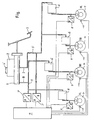
- FIG. 1 In this circuit diagram is the hydraulic one according to the invention Brake system for motor vehicles shown in a roughly simplified manner.
- the plan shows a master cylinder 1 which is attached to a caster or Reservoir 2 for brake fluid is connected, which is usually closed by a screwable cover 2 ' is.
- the master cylinder 1 is operated by a pedal device 3 operated, this directly or indirectly via a brake booster, not shown here happen can.
- the hydraulic brake system has a primary and a secondary circuit (I, II), with a diagonal division in the figure is shown, i.e. the wheel brakes 4 in front right (VR) and rear left (HL) and wheel brakes 4 rear right (HR) and front left (VL) are over each other Brake fluid lines 5 connected.
- the invention can also be a hydraulic one Act the brake system with a different division.
- Components 6, which are, for example, a Pump, valve or the like can only act as a black box shown.
- Pressure sensors 7, 8 available, with the help of the brake fluid pressures at different points in the respective brake circuits I, II recorded and converted into an electronic signal become. These signals are preferred in the invention pressure warning device 9 integrated in the on-board computer and processed there. If the pressure warning device 9 is trained in the on-board computer, there can also be other electronic ones Signals, for example from wheel sensors 10, are evaluated become.
- the pressure warning device 9 as a circuit failure indicator are preferably the electronic signals of the Compression voltage converter 7, which is particularly close to the Master cylinder 1 are attached, evaluated. exceeds the pressure difference in the brake circuits I, II a certain Value, this is done electronically by the pressure warning device 9 a signal, for example in the form of a warning lamp, to the driver of the motor vehicle.
- the signals of the pressure-voltage converter 7 can also be used individually be evaluated so that an error warning to the driver occurs when a single brake circuit I, II fails and that sensor 7 reports a signal that a predetermined, for example, falls below the target value determined in experiments.
- the present invention to a conventional container warning device that has a Float is activated when the brake fluid level falls below a minimum value in container 2, are waived.
- the circuit failure device 9 only reports the circuit failure a brake circuit I, II with the brake pedal 3 actuated, so while driving.
- the hold tank 2 according to the invention in an advantageous manner at least partially transparent, for example with a shop window or completely transparent formed and has a level marker, which can be designed as a max-min display.
- the fill level the brake fluid is in the installed state easy to check without opening the container closure 2 ', so that when refueling or some other inspection can be perceived from the outside.
- the brake lights one Motor vehicle be turned on or off. Switching on takes place when the signal of at least one pressure-voltage converter 7, 8 a setpoint which is in turn predetermined exceeds. If it falls below this setpoint again the brake lights switch off automatically. The brake lights can also be switched off, if the value falls below another setpoint, the lower one than this one is.
- the brake lights are over near the Wheel brakes 4 attached pressure-voltage converter 8 switched, because here the signal of an actual braking is the fastest is present. But it is also possible to use the brake lights to switch over the sensors 7 when a quick response to an actual actuation of the brake pedal 3 by the Driver is desired.
Description
Die vorliegende Erfindung betrifft eine hydraulische Bremsanlage für Kraftfahrzeuge gemäß dem Oberbegriff von Anspruch 1 und ein Verfahren zur Auswertung des Bremsflüssigkeitsdruckes an verschiedenen Punkten einer solchen Anlage.The present invention relates to a hydraulic brake system for motor vehicles according to the preamble of claim 1 and a method for evaluating the brake fluid pressure at various points in such a facility.
Eine derartige hydraulische Bremsanlage für Kraftfahrzeuge ist beispielsweise aus der DE 44 38 927 bekannt. Diese Druckschrift offenbart eine Bremsanlage, welche außer einer Bremsschlupfregelung auch eine Antriebsschlupfregelung oder eine anderweitige Fahrstabilitätsregelung vornehmen kann. Insbesondere für die Schlupfregelung werden die Flüssigkeitsdrücke an verschiedenen Stellen der Bremsleitungen über Druckaufnehmer gemessen und in einer Einrichtung ausgewertet, um beispielsweise eine Pumpe an- oder abzuschalten.Such a hydraulic brake system for motor vehicles is known for example from DE 44 38 927. This Document discloses a brake system, which besides one Brake slip control also a traction control system or can make a different driving stability regulation. The fluid pressures are particularly important for slip control at various points in the brake lines Pressure transducer measured and evaluated in a facility, for example to switch a pump on or off.
In hydraulischen Bremsanlagen wird heutzutage ein mechanischer Bremsdruckwarnschalter eingesetzt. Die DE 35 42 824 offenbart beispielsweise einen derartigen hydraulischen Differenzdruckwarnschalter, über den bestehende Druckdifferenzen in den beiden Bremskreisen hydraulisch sensiert und weitergeleitet werden. Diese mechanischen Schalter besitzen ein hohes Gewicht und können nur unter hohen Kosten gefertigt werden.In hydraulic brake systems nowadays, a mechanical one Brake pressure warning switch inserted. DE 35 42 824 discloses, for example, such a hydraulic differential pressure warning switch, over the existing pressure differences hydraulically sensed and forwarded in the two brake circuits become. These mechanical switches have a heavy weight and can only be manufactured at high cost.
Aus der DE 33 47 819 ist ein Bremslichtschalter für Kraftfahrzeuge bekannt. Dabei werden die Bremslichter eines Kraftfahrzeuges über einen am Pedalbock angeordneten mechanischen Schalter betätigt. Ein derartiger Schalter ist relativ schwer, teuer und muß aufwendig mit dem Pedalbock verbunden werden.DE 33 47 819 is a brake light switch for Motor vehicles known. The brake lights become one Motor vehicle via a mechanical arranged on the pedal bracket Switch operated. Such a switch is relative heavy, expensive and must be connected to the pedal bracket become.
Desweiteren ist aus der DE 40 29 793 A1 eine hydraulische Fahrzeugbremsanlage bekannt, bei der Drucksensoren zur warnung vor einem Druckabfall in der Anlage vorgesehen sind.Furthermore, from DE 40 29 793 A1 is a hydraulic Vehicle brake system known in the pressure sensors for warning of a pressure drop in the system are.
Der vorliegenden Erfindung liegt deshalb die Aufgabe zugrunde, eine hydraulische Bremsanlage der eingangs beschriebenen Art vorzuschlagen, bei der die mit dem Bremsflüssigkeitsdruck zusammenhängenden Warneinrichtungen kostengünstig ausgeführt sind und ein geringes Gewicht aufweisen.The present invention is therefore based on the object a hydraulic brake system of the type described above to propose where the brake fluid pressure related Warning devices are inexpensive and are light in weight.
Diese Aufgabe wird erfindungsgemäß in Verbindung mit den kennzeichnenden Merkmalen von Anspruch 1 gelöst. Dazu ist bei einer gattungsgemäßen hydraulischen Bremsanlage zumindest eine elektronische Druckwarneinrichtung vorgesehen, welche ferner als Bremslicht betätigungseinrichtung vorgesehen ist und für die in vorteilhafter Weise die ohnehin in einer derartigen Bremsanlage vorhandenen Drucksensoren genutzt werden. Mittels der Erfindung können die obigen, bisher mechanisch ausgebildeten Warneinrichtungen wegfallen.This task is inventively in connection with the characteristic Features of claim 1 solved. This is with one Generic hydraulic brake system at least one electronic Pressure warning device is provided, which is also provided as a brake light actuating device and for which in an advantageous manner Way the existing in such a brake system pressure sensors be used. By means of the invention, the above, previously mechanically trained warning devices are eliminated.
In der bevorzugten Ausführungsform ist die Druckwarneinrichtung dabei als Anzeige für den Ausfall eines Bremskreises ausgeführt. Diese elektronische Kreisausfallanzeige übernimmt dabei die Aufgaben, die bisher von der hydraulischen Differenzdruckwarneinrichtung ausgeführt worden sind. In the preferred embodiment, the pressure warning device executed as a display for the failure of a brake circuit. This electronic circuit failure indicator takes over the tasks previously performed by the hydraulic differential pressure warning device have been carried out.
Wenn der Nachlaufbehälter in vorteilhafter Weise zumindest teilweise transparent ausgebildet ist, eine Füllstandsmarkierung aufweist und der Füllstand der Bremsflüssigkeit im eingebauten Zustand ohne Öffnen des Behälterverschlusses überprüfbar ist, kann bei der hydraulischen Bremsanlage erfindungsgemäß auf eine mit einem Schwimmer ausgeführte Behälterwarneinrichtung verzichtet werden. Über den Schwimmer wird dabei üblicherweise das Niveau der Bremsflüssigkeit aufgenommen und bei zu niedrigem Flüssigkeitsstand eine Warneinrichtung betätigt. Wenn die erfindungsgemäße Druckwarneinrichtung als Kreisausfallanzeige ausgeführt ist, entfällt eine derartige Warneinrichtung. Da der Kreisausfall, wie später beschrieben, nur bei betätigtem Bremspedal gemeldet wird, muß der Bremsflüssigkeitsbehälter einsehbar sein, damit ein Absinken des Bremsflüssigkeitsstandes optisch, zum Beispiel bei einer routinemäßigen Wartung des Kraftfahrzeuges, wahrgenommen werden kann.If the trailing container in an advantageous manner at least is partially transparent, a level marker and the level of the brake fluid in the built-in Condition can be checked without opening the container closure is according to the invention in the hydraulic brake system on a container warning device designed with a float to be dispensed with. About the swimmer the level of the brake fluid is usually recorded and a warning device if the liquid level is too low actuated. If the pressure warning device according to the invention is designed as a circular failure indicator, there is no such indicator Warning device. Since the circuit failure, as described later, The brake fluid reservoir must only be signaled when the brake pedal is pressed be visible so that the brake fluid level drops optically, for example with a routine Maintenance of the motor vehicle can be performed.
In der bevorzugten Ausführungsform der vorliegenden Erfindung ist die Druckwarneinrichtung in einem Bordcomputer integriert, der ohnehin heutzutage in vielen Neuwagen vorhanden ist.In the preferred embodiment of the present invention the pressure warning device is integrated in an on-board computer, which is already present in many new cars these days.
Erfindungsgemäß werden die von den Druck-sensoren ausgehende Signale in zumindest einer elektronischen Druckwarneinrichtung aufgenommen und verarbeitet.According to the invention, those emanating from the pressure sensors Signals in at least one electronic pressure warning device recorded and processed.
Dabei werden die Signale der Druck-sensoren vorzugsweise getrennt ausgewertet, sie können aber auch zusammen aufgenommen und verarbeitet werden. The signals from the pressure sensors are preferred evaluated separately, but they can also be recorded together and processed.
Eine Anzeige für den Ausfall eines Bremskreises erfolgt bei betätigter Pedaleinrichtung erfindungsgemäß, wenn das Ausgangssignal zumindest eines Druck-sensors einen vorgegebenen Sollwert unterschreitet. Derartige Sollwerte können beispielsweise in Abhängigkeit von der Pedalbetätigungskraft leicht über Versuche ermittelt werden.An indication of a brake circuit failure occurs when the brake is actuated Pedal device according to the invention when the output signal at least one pressure sensor a predetermined one Falls below the setpoint. Such setpoints can for example depending on the pedal actuation force can be easily determined via experiments.
Dabei erfolgt die Kreisausfallanzeige vorzugsweise, wenn die Differenz der Signale von wenigstens zwei in verschiedenen Kreisen angeordneten Druck-sensoren einen vorgegebenen Sollwert überschreitet.The circuit failure display is preferably carried out when the Difference of signals from at least two in different Circles arranged pressure sensors a predetermined Setpoint exceeds.
Erfindungsgemäß können auch die Bremslichter des Kraftfahrzeuges eingeschaltet werden, wenn das Signal zumindest eines Drucksensors einen vorgegebenen Sollwert überschreitet. Dieser Sollwert kann analog zu oben, beispielsweise auch in Abhängigkeit vom Fahrzeugtyp, ermittelt werden.According to the invention, the brake lights of the motor vehicle can also be turned on when the signal is at least one Pressure sensor exceeds a predetermined setpoint. This setpoint can be analogous to the above, for example also depending on the vehicle type.
Analog werden die Bremslichter des Kraftfahrzeuges ausgeschaltet, wenn die Signale der Druck-sensoren einen ebenfalls vorgegebenen und entsprechend tiefer liegenden Sollwert unterschreiten.The brake lights of the motor vehicle are switched off analogously, if the signals from the pressure sensors are too specified and correspondingly lower setpoint below.
Die Auswertung der von den Druck-sensoren ausgehenden Signale wird dabei bevorzugt in einem Bordcomputer vorgenommen.The evaluation of those originating from the pressure sensors Signals are preferably carried out in an on-board computer.
Eine nähere Erläuterung des Erfindungsgedankens erfolgt nun in Zusammenhang mit der einzigen
- Fig.,
- die einen vereinfachten Schaltplan der hydraulischen Bremsanlage gemäß der vorliegenden Erfindung zeigt.
- FIG.
- which shows a simplified circuit diagram of the hydraulic brake system according to the present invention.
In diesem Schaltplan ist die erfindungsgemäße hydraulische
Bremsanlage für Kraftfahrzeuge grob vereinfacht dargestellt.
Der Plan zeigt einen Hauptzylinder 1, der an einem Nachlaufoder
Vorratsbehälter 2 für Bremsflüssigkeit angeschlossen ist,
welcher üblicherweise durch einen schraubbaren Deckel 2' verschlossen
ist. Der Hauptzylinder 1 wird über eine Pedaleinrichtung
3 betätigt, wobei dies direkt oder indirekt über
einen hier nicht dargestellten Bremskraftverstärker geschehen
kann.In this circuit diagram is the hydraulic one according to the invention
Brake system for motor vehicles shown in a roughly simplified manner.
The plan shows a master cylinder 1 which is attached to a caster or
Die hydraulische Bremsanlage weist einen Primär- und einen Sekundärkreislauf
(I, II) auf, wobei in der Fig. eine Diagonalaufteilung
dargestellt ist, d.h. die Radbremsen 4 vorne
rechts (VR) und hinten links (HL) sowie die Radbremsen 4 hinten
rechts (HR) und vorne links (VL) sind jeweils miteinander über
Bremsflüssigkeitsleitungen 5 verbunden. Bei der vorliegenden
Erfindung kann es sich jedoch auch um um eine hydraulische
Bremsanlage mit einer anderen Aufteilung handeln. Zur Vereinfachung
des Schaltplanes sind nicht erfindungswesentliche hydraulische
Bauteile 6, bei denen es sich beispielsweise um eine
Pumpe, ein Ventil oder ähnliches handeln kann, nur als Black-Box
dargestellt.The hydraulic brake system has a primary and a secondary circuit
(I, II), with a diagonal division in the figure
is shown, i.e. the
In der Bremsanlage sind als Druckspannungswandler ausgebildete
Drucksensoren 7, 8 vorhanden, mit deren Hilfe die Bremsflüssigkeitsdrücke
an verschiedenen Stellen der jeweiligen Bremskreise
I, II aufgenommen und in ein elektronisches Signal umgewandelt
werden. Diese Signale werden in der erfindungsgemäßen, vorzugsweise
im Bordcomputer integrierten Druckwarneinrichtung 9 aufgenommen
und dort verarbeitet. Wenn die Druckwarneinrichtung 9
im Bordcomputer ausgebildet ist, können dort auch andere elektronische
Signale, beispielsweise von Radsensoren 10, ausgewertet
werden. In the brake system are trained as a compressive voltage
Für die Nutzung der Druckwarneinrichtung 9 als Kreisausfallanzeige
werden vorzugsweise die elektronischen Signale der
Druckspannungswandler 7, die insbesondere in der Nähe des
Hauptzylinders 1 angebracht sind, ausgewertet. Überschreitet
die Druckdifferenz in den Bremskreisen I, II einen bestimmten
Wert, so erfolgt elektronisch von der Druckwarneinrichtung 9
ein Signal, beispielsweise in Form einer Warnlampe, an den Fahrer
des Kraftfahrzeuges.For the use of the
Die Signale der Druckspannungswandler 7 können aber auch einzeln
ausgewertet werden, so daß eine Fehlerwarnung an den Fahrer
erfolgt, wenn ein einzelner Bremskreis I, II ausfällt und
derjenige Sensor 7 ein Signal meldet, daß einen vorgegebenen,
beispielsweise in Versuchen ermittelten Sollwert unterschreitet.The signals of the pressure-
Da eine derartige Kreisausfallanzeige nur bei betätigtem
Bremspedal 3 erfolgt, muß an dieser Stelle beispielsweise die
Betätigungskraft durch den Fahrer gemessen werden, um eine genaue
Anzeige des Kreisausfalls zu ermöglichen. Die Betätigungskraft
des Pedals 3 wird dazu bevorzugt ebenfalls durch den
Bordcomputer, bzw. die Druckwarneinrichtung 9 aufgenommen und
verarbeitet.Since such a circuit failure indicator only when activated
Brake pedal 3 takes place at this point, for example
Operating force can be measured by the driver to give an accurate
Allow display of the circle failure. The actuation force
of the pedal 3 is also preferred by the
On-board computer, or the
In besonders vorteilhafter Weise kann durch die vorliegende Erfindung
auf eine übliche Behälterwarneinrichtung, die über einen
Schwimmer aktiviert wird, wenn das Bremsflüssigkeitsniveau
im Behälter 2 einen Minimalwert unterschreitet, verzichtet werden.
Die Kreisausfalleinrichtung 9 meldet jedoch nur den Kreisausfall
eines Bremskreises I, II bei betätigten Bremspedal 3,
also während der Fahrt. Wenn das Kraftfahrzeug jedoch längere
Zeit stillsteht, kann es durch Undichtigkeiten im Bremssystem
zu einer schleichenden Leckage kommen, die vom Fahrer nicht
wahrgenommen wird. Aus diesem Grunde ist der Nachlaufbehälter 2
erfindungsgemäß in vorteilhafter Weise zumindest teilweise
transparent, beispielsweise
mit einem Schaufenster oder vollständig durchsichtig
ausgebildet und weist eine Füllstandsmarkierung auf,
die als Max.-Min.-Anzeige ausgeführt sein kann. Der Füllstand
der Bremsflüssigkeit ist dadurch im eingebauten Zustand
ohne Öffnen des Behälterverschlusses 2' leicht überprüfbar,
so daß dieser beim Tanken oder einer anderen Inspektion
von außen wahrgenommen werden kann.In a particularly advantageous manner, the present invention
to a conventional container warning device that has a
Float is activated when the brake fluid level
falls below a minimum value in
In einer Weiterbildung der vorliegenden Erfindung können
über die Druckwarneinrichtung 9 auch die Bremslichter eines
Kraftfahrzeuges ein- bzw. ausgeschaltet werden. Das Einschalten
erfolgt, wenn das Signal zumindest eines Druckspannungswandlers
7, 8 einen wiederum vorgegebenen Sollwert
überschreitet. Wenn dieser Sollwert wieder unterschritten
wird, schalten sich die Bremslichter automatisch wieder aus.
Das Ausschalten der Bremslichter kann aber auch erfolgen,
wenn ein anderer Sollwert unterschritten wird, der niedriger
als dieser ist.In a further development of the present invention
via the
vorzugsweise werden die Bremslichter über in der Nähe der
Radbremsen 4 angebrachte Druckspannungswandler 8 geschaltet,
da hier das Signal einer tatsächlichen Bremsung am schnellsten
vorliegt. Es ist aber auch möglich, die Bremslichter
über die Sensoren 7 zu schalten, wenn eine schnelle Reaktion
auf eine tatsächliche Betätigung des Bremspedals 3 durch den
Fahrer erwünscht ist. preferably the brake lights are over near the
- 11
- Hauptzylindermaster cylinder
- 22
- NachlaufbehälterAn expansion reservoir
- 2'2 '
- Behälterverschlußcontainer closure
- 33
- Pedaleinrichtungpedal device
- 44
- Radbremsewheel brake
- 55
- Bremsleitungbrake line
- 66
- Hydraulikbauteilhydraulic component
- 77
- DruckspannungswandlerPressure voltage transformer
- 88th
- DruckspannungswandlerPressure voltage transformer
- 99
- Druckwarneinrichtung bzw. BordcomputerPressure warning device or on-board computer
- II
- PrimärbremskreisPrimary brake circuit
- IIII
- SekundärbremskreisSecondary brake circuit
Claims (11)
- Hydraulic brake system for motor vehicles comprising a master cylinder (1) connected to a supply reservoir (2) for brake fluid and actuated by a pedal device (3), at least two wheel brakes (4) connected by way of brake lines (5) and hydraulic components (6) to the master cylinder (1) and actuated by the latter by way of various brake circuits (I, II), and at least one pressure sensor (7, 8), characterized in that at least one electronic pressure warning device (9) is provided in the hydraulic brake system, and in that the pressure warning device (9) is further used as a brake light actuating device.
- Hydraulic brake system as claimed in claim 1,
characterized in that the pressure warning device (9) is configured as an indicator of a failure of brake circuit (I, II). - Hydraulic brake system as claimed in claim 2,
characterized in that the supply reservoir (2) is at least partially transparent and has a full mark, and the filling state of the brake fluid can be checked in the built-in state without opening a reservoir cover (2'). - Hydraulic brake system as claimed in any one of the preceding claims,
characterized in that the pressure warning device (9) is integrated into an onboard computer (9). - Process for evaluating brake fluid pressures in a hydraulic brake system for motor vehicles comprising a master cylinder (1) connected to a supply reservoir (2) for brake fluid and actuated by a pedal device (3), at least two wheel brakes (4) connected by way of brake lines (5) and hydraulic components (6) to the master cylinder (1) and actuated by the latter by way of various brake circuits (I, II), and at least one pressure sensor (7, 8), characterized in that signals coming from the pressure sensor (7, 8) are evaluated in at least one electronic pressure warning device (9), and that the pressure warning device (9) is further used as a brake light actuating device.
- Process as claimed in claim 5,
characterized in that the signals of the pressure sensors (7, 8) are evaluated separately. - Process as claimed in claim 6,
characterized in that when the pedal device (3) is operated, a failure of a brake circuit (I, II) is indicated when the signal of at least one pressure sensor (7, 8) falls below a preset nominal value. - Process as claimed in claim 5 or 6,
characterized in that when the pedal device (3) is operated, circuit failure is indicated when the difference of the signals of at least two pressure sensors (7, 8) arranged in various circuits (I, II) exceeds a preset nominal value. - Process as claimed in claim 5 or 6,
characterized in that the brake lights of the motor vehicle are switched on when the signal of at least one pressure sensor (7, 8) exceeds a preset nominal value. - Process as claimed in claim 5 or 6,
characterized in that the brake lights of the motor vehicle are switched off when the signals of the pressure sensors (7, 8) fall below a preset nominal value. - Process as claimed in any one of claims 5 to 10,
characterized in that the signals coming from the pressure sensors (7, 8) are evaluated in an onboard computer (9).
Applications Claiming Priority (3)
| Application Number | Priority Date | Filing Date | Title |
|---|---|---|---|
| DE19626306A DE19626306A1 (en) | 1996-07-01 | 1996-07-01 | Hydraulic brake system for motor vehicles |
| DE19626306 | 1996-07-01 | ||
| PCT/EP1997/003294 WO1998000326A1 (en) | 1996-07-01 | 1997-06-24 | Hydraulic brake system for motor vehicles |
Publications (2)
| Publication Number | Publication Date |
|---|---|
| EP0907539A1 EP0907539A1 (en) | 1999-04-14 |
| EP0907539B1 true EP0907539B1 (en) | 2004-01-21 |
Family
ID=7798519
Family Applications (1)
| Application Number | Title | Priority Date | Filing Date |
|---|---|---|---|
| EP97929271A Expired - Lifetime EP0907539B1 (en) | 1996-07-01 | 1997-06-24 | Hydraulic brake system for motor vehicles |
Country Status (3)
| Country | Link |
|---|---|
| EP (1) | EP0907539B1 (en) |
| DE (2) | DE19626306A1 (en) |
| WO (1) | WO1998000326A1 (en) |
Cited By (1)
| Publication number | Priority date | Publication date | Assignee | Title |
|---|---|---|---|---|
| CN101786450A (en) * | 2010-02-26 | 2010-07-28 | 吉林大学 | Vehicle brake pipeline pressure monitor and early warning system for |
Families Citing this family (4)
| Publication number | Priority date | Publication date | Assignee | Title |
|---|---|---|---|---|
| DE19804077A1 (en) * | 1998-02-03 | 1999-08-12 | Uwe Rehwald | Car brake installation |
| DE10018178A1 (en) * | 2000-04-12 | 2001-10-25 | Bayerische Motoren Werke Ag | Electrically controlled, in particular electromechanical, braking system for a motor vehicle |
| DE102018202287A1 (en) * | 2018-02-15 | 2019-08-22 | Robert Bosch Gmbh | Electrohydraulic power vehicle brake system for an autonomous land vehicle |
| CN110936945B (en) * | 2019-11-11 | 2021-03-09 | 南京航空航天大学 | Disc brake self-detection system and method based on multi-sensor fusion |
Family Cites Families (21)
| Publication number | Priority date | Publication date | Assignee | Title |
|---|---|---|---|---|
| DE1731875U (en) * | 1956-06-14 | 1956-10-11 | Gerhard Dinter | BRAKE FLUID RESERVOIR FOR MOTOR VEHICLES. |
| DE2316992C3 (en) * | 1969-12-10 | 1981-05-14 | Alfred Teves Gmbh, 6000 Frankfurt | Warning switch for hydraulic dual-circuit brake systems |
| US3827522A (en) * | 1973-08-10 | 1974-08-06 | Koehring Co | Fluid pressure actuated brake light switch |
| US4414630A (en) * | 1980-03-19 | 1983-11-08 | Lucas Industries Limited | Anti-skid vehicle braking systems |
| US4335167A (en) * | 1980-06-02 | 1982-06-15 | Edison International, Inc. | Brake fluid reservoir comprising polymethylpentene and 10-20% glass fibers |
| DE3137200A1 (en) * | 1981-09-18 | 1983-03-31 | Robert Bosch Gmbh, 7000 Stuttgart | TWO-CIRCUIT BRAKING DEVICE |
| EP0112194A1 (en) * | 1982-11-01 | 1984-06-27 | The Bendix Corporation | A warning device for a vehicle brake system |
| DE3511579A1 (en) * | 1985-03-29 | 1986-10-02 | Robert Bosch Gmbh, 7000 Stuttgart | Method and device for controlling the brake pressure in vehicle brake systems |
| DE3601914C2 (en) * | 1986-01-23 | 1996-05-15 | Teves Gmbh Alfred | Hydraulic brake system for motor vehicles |
| DE3713662C2 (en) * | 1987-04-24 | 1996-02-29 | Teves Gmbh Alfred | Electro-hydraulic device for the continuous monitoring of the pressure in a hydraulic motor vehicle brake system |
| DE3829949A1 (en) * | 1988-09-03 | 1990-03-15 | Daimler Benz Ag | METHOD FOR OPERATING AN ELECTRIC PRESSURE OPERATING BRAKE DEVICE AND CONTROL DEVICE FOR CARRYING OUT THE METHOD |
| GB8905311D0 (en) | 1989-03-08 | 1989-04-19 | Lucas Ind Plc | Electronic braking system |
| DE3922947A1 (en) * | 1989-07-12 | 1991-01-17 | Bosch Gmbh Robert | HYDRAULIC VEHICLE BRAKE SYSTEM |
| DE4029793C2 (en) * | 1990-09-20 | 1999-05-06 | Bosch Gmbh Robert | Hydraulic vehicle brake system |
| DE4037662A1 (en) * | 1990-11-27 | 1992-06-04 | Bosch Gmbh Robert | Hydraulic braking system with servo unit - has plungers which provide precise front-wheel pressure modulation and rear-wheel pressure amplification in antilock braking operation |
| DE4132767C2 (en) * | 1991-10-02 | 1995-09-14 | Daimler Benz Ag | Method for diagnosing an electronically controlled pressure medium braking device of a vehicle |
| DE4241410A1 (en) * | 1992-12-09 | 1994-06-16 | Martin Reber | Road vehicle with hydraulically operated brakes and brake warning lamps - gives prompt warning to following driver by either flashing or periodic increase and decrease of brightness |
| JPH07315209A (en) | 1994-05-27 | 1995-12-05 | Akebono Brake Ind Co Ltd | Brake method of vehicle |
| DE4430168B4 (en) * | 1994-08-25 | 2004-12-02 | Robert Bosch Gmbh | vehicle brake system |
| DE4438927A1 (en) * | 1994-10-31 | 1996-05-02 | Teves Gmbh Alfred | Hydraulic brake system for driving stability control |
| DE4447029A1 (en) * | 1994-12-28 | 1996-07-04 | Schleussner Horst Thomas | Motor vehicle braking lights flasher |
-
1996
- 1996-07-01 DE DE19626306A patent/DE19626306A1/en not_active Withdrawn
-
1997
- 1997-06-24 DE DE59711239T patent/DE59711239D1/en not_active Expired - Lifetime
- 1997-06-24 WO PCT/EP1997/003294 patent/WO1998000326A1/en active IP Right Grant
- 1997-06-24 EP EP97929271A patent/EP0907539B1/en not_active Expired - Lifetime
Cited By (1)
| Publication number | Priority date | Publication date | Assignee | Title |
|---|---|---|---|---|
| CN101786450A (en) * | 2010-02-26 | 2010-07-28 | 吉林大学 | Vehicle brake pipeline pressure monitor and early warning system for |
Also Published As
| Publication number | Publication date |
|---|---|
| DE19626306A1 (en) | 1998-01-08 |
| DE59711239D1 (en) | 2004-02-26 |
| EP0907539A1 (en) | 1999-04-14 |
| WO1998000326A1 (en) | 1998-01-08 |
Similar Documents
| Publication | Publication Date | Title |
|---|---|---|
| EP3371017B1 (en) | Pneumatic braking device for a utility vehicle | |
| DE102007042316B4 (en) | Electronic braking system for a utility vehicle and method for controlling an electronic braking system | |
| DE102008003379A1 (en) | Brake system for a vehicle and brake pedal device for such a brake system | |
| DE19607788A1 (en) | Method and device for controlling the approach of a vehicle to an obstacle | |
| DE10343174A1 (en) | Device and method for controlling the speed of a vehicle when maneuvering / parking the vehicle | |
| EP3371020B1 (en) | Pneumatic braking device | |
| DE19532331A1 (en) | Tire pressure monitoring arrangement | |
| DE10004086C2 (en) | Brake system for vehicles, in particular commercial vehicles | |
| DE19834126B4 (en) | Method and device for operating a braking device in motor vehicles | |
| DE102015222624A1 (en) | Method and monitoring device for operating a motor vehicle | |
| DE102006035913A1 (en) | Combined vehicle brake system with hydraulically and electromechanically actuated wheel brakes | |
| EP0907539B1 (en) | Hydraulic brake system for motor vehicles | |
| DE10325650A1 (en) | Braking device and method for a vehicle | |
| DE19955798A1 (en) | Trailer detection device detects connection of trailer coupled to tractor via compressed air coupling from time variation of pressure in pneumatic chamber, e.g. line, sealed from atmosphere | |
| DE102020210598A1 (en) | Procedure for checking the availability of a hydraulic fallback level in an electronically slip-controllable power brake system; Electronic control unit for an electronically slip-controllable external power brake system and electronically slip-controllable external power brake system with an electronic control unit | |
| DE19933961A1 (en) | Monitoring functional state and wear of brakes involves evaluating wear and/or functional readiness of braking device(s), comparing measurement signals for tractor and/or trailer | |
| EP2025569B1 (en) | Auxiliary brake for commercial vehicles | |
| DE102016212412B4 (en) | Method for bleeding a hydraulic brake system of a motor vehicle and motor vehicle | |
| DE10224399A1 (en) | Vehicle with automatic distance regulation, anti-lock braking system and anti-slip regulation system brakes drive axle or axles with aid of anti-slip regulation function for deceleration | |
| DE102005004576A1 (en) | Brake system for e.g. passenger car, has brake booster with brake pedal and wheel brake actuator, temperature sensor for detection of heating of actuator, and evaluation device for determination of energy equivalents | |
| DE19532624C1 (en) | Control device and control method for tilting truck and trailer bridges | |
| EP0989039B1 (en) | Brake device for a mobile machine | |
| DE102016006637B4 (en) | Direction indicator control module | |
| DE102017004112A1 (en) | Method for operating a light horn function of a vehicle | |
| EP3647135B1 (en) | Electronic braking system |
Legal Events
| Date | Code | Title | Description |
|---|---|---|---|
| PUAI | Public reference made under article 153(3) epc to a published international application that has entered the european phase |
Free format text: ORIGINAL CODE: 0009012 |
|
| 17P | Request for examination filed |
Effective date: 19990201 |
|
| AK | Designated contracting states |
Kind code of ref document: A1 Designated state(s): DE FR GB |
|
| RAP1 | Party data changed (applicant data changed or rights of an application transferred) |
Owner name: CONTINENTAL TEVES AG & CO. OHG |
|
| TPAD | Observations filed by third parties |
Free format text: ORIGINAL CODE: EPIDOS TIPA |
|
| 17Q | First examination report despatched |
Effective date: 20010613 |
|
| GRAH | Despatch of communication of intention to grant a patent |
Free format text: ORIGINAL CODE: EPIDOS IGRA |
|
| GRAS | Grant fee paid |
Free format text: ORIGINAL CODE: EPIDOSNIGR3 |
|
| GRAA | (expected) grant |
Free format text: ORIGINAL CODE: 0009210 |
|
| AK | Designated contracting states |
Kind code of ref document: B1 Designated state(s): DE FR GB |
|
| PG25 | Lapsed in a contracting state [announced via postgrant information from national office to epo] |
Ref country code: GB Free format text: LAPSE BECAUSE OF FAILURE TO SUBMIT A TRANSLATION OF THE DESCRIPTION OR TO PAY THE FEE WITHIN THE PRESCRIBED TIME-LIMIT Effective date: 20040121 |
|
| REG | Reference to a national code |
Ref country code: GB Ref legal event code: FG4D Free format text: NOT ENGLISH |
|
| REF | Corresponds to: |
Ref document number: 59711239 Country of ref document: DE Date of ref document: 20040226 Kind code of ref document: P |
|
| GBV | Gb: ep patent (uk) treated as always having been void in accordance with gb section 77(7)/1977 [no translation filed] |
Effective date: 20040121 |
|
| REG | Reference to a national code |
Ref country code: FR Ref legal event code: RN |
|
| REG | Reference to a national code |
Ref country code: FR Ref legal event code: FC |
|
| PLBE | No opposition filed within time limit |
Free format text: ORIGINAL CODE: 0009261 |
|
| STAA | Information on the status of an ep patent application or granted ep patent |
Free format text: STATUS: NO OPPOSITION FILED WITHIN TIME LIMIT |
|
| 26N | No opposition filed |
Effective date: 20041022 |
|
| EN | Fr: translation not filed | ||
| EN | Fr: translation not filed | ||
| ET | Fr: translation filed | ||
| REG | Reference to a national code |
Ref country code: FR Ref legal event code: ERR Free format text: BOPI DE PUBLICATION N: 05/03 PAGES: 237 PARTIE DU BULLETIN CONCERNEE: BREVETS EUROPEENS DONT LA TRADUCTION N'A PAS ETE REMISE A I'INPI IL Y A LIEU DE SUPPRIMER: LA MENTION DE LA NON REMISE. |
|
| PGFP | Annual fee paid to national office [announced via postgrant information from national office to epo] |
Ref country code: FR Payment date: 20060619 Year of fee payment: 10 |
|
| PGFP | Annual fee paid to national office [announced via postgrant information from national office to epo] |
Ref country code: DE Payment date: 20070630 Year of fee payment: 11 |
|
| REG | Reference to a national code |
Ref country code: FR Ref legal event code: ST Effective date: 20080229 |
|
| PG25 | Lapsed in a contracting state [announced via postgrant information from national office to epo] |
Ref country code: DE Free format text: LAPSE BECAUSE OF THE APPLICANT RENOUNCES Effective date: 20080219 |
|
| PG25 | Lapsed in a contracting state [announced via postgrant information from national office to epo] |
Ref country code: FR Free format text: LAPSE BECAUSE OF NON-PAYMENT OF DUE FEES Effective date: 20070702 |