EP0906493B1 - Turbomachine et procede de refroidissement d'une turbomachine - Google Patents
Turbomachine et procede de refroidissement d'une turbomachine Download PDFInfo
- Publication number
- EP0906493B1 EP0906493B1 EP97928113A EP97928113A EP0906493B1 EP 0906493 B1 EP0906493 B1 EP 0906493B1 EP 97928113 A EP97928113 A EP 97928113A EP 97928113 A EP97928113 A EP 97928113A EP 0906493 B1 EP0906493 B1 EP 0906493B1
- Authority
- EP
- European Patent Office
- Prior art keywords
- cooling
- turbomachine
- rotor
- fluid
- feed
- Prior art date
- Legal status (The legal status is an assumption and is not a legal conclusion. Google has not performed a legal analysis and makes no representation as to the accuracy of the status listed.)
- Expired - Lifetime
Links
- 238000001816 cooling Methods 0.000 title claims abstract description 35
- 238000000034 method Methods 0.000 title abstract description 11
- 239000012530 fluid Substances 0.000 claims description 31
- 239000012809 cooling fluid Substances 0.000 claims description 29
- 230000004888 barrier function Effects 0.000 description 6
- 230000000694 effects Effects 0.000 description 2
- 239000000463 material Substances 0.000 description 2
- 229910000669 Chrome steel Inorganic materials 0.000 description 1
- 239000000969 carrier Substances 0.000 description 1
- 229910000734 martensite Inorganic materials 0.000 description 1
Images
Classifications
-
- F—MECHANICAL ENGINEERING; LIGHTING; HEATING; WEAPONS; BLASTING
- F01—MACHINES OR ENGINES IN GENERAL; ENGINE PLANTS IN GENERAL; STEAM ENGINES
- F01D—NON-POSITIVE DISPLACEMENT MACHINES OR ENGINES, e.g. STEAM TURBINES
- F01D9/00—Stators
- F01D9/06—Fluid supply conduits to nozzles or the like
- F01D9/065—Fluid supply or removal conduits traversing the working fluid flow, e.g. for lubrication-, cooling-, or sealing fluids
-
- F—MECHANICAL ENGINEERING; LIGHTING; HEATING; WEAPONS; BLASTING
- F01—MACHINES OR ENGINES IN GENERAL; ENGINE PLANTS IN GENERAL; STEAM ENGINES
- F01D—NON-POSITIVE DISPLACEMENT MACHINES OR ENGINES, e.g. STEAM TURBINES
- F01D3/00—Machines or engines with axial-thrust balancing effected by working-fluid
- F01D3/02—Machines or engines with axial-thrust balancing effected by working-fluid characterised by having one fluid flow in one axial direction and another fluid flow in the opposite direction
-
- F—MECHANICAL ENGINEERING; LIGHTING; HEATING; WEAPONS; BLASTING
- F01—MACHINES OR ENGINES IN GENERAL; ENGINE PLANTS IN GENERAL; STEAM ENGINES
- F01D—NON-POSITIVE DISPLACEMENT MACHINES OR ENGINES, e.g. STEAM TURBINES
- F01D5/00—Blades; Blade-carrying members; Heating, heat-insulating, cooling or antivibration means on the blades or the members
- F01D5/02—Blade-carrying members, e.g. rotors
- F01D5/08—Heating, heat-insulating or cooling means
Definitions
- the invention relates to a turbomachine, in particular one Steam turbine, with a housing and at least partially inflow area for action fluid formed by the housing and a method for cooling at least one Inflow area of a component assigned to a turbomachine.
- the object of the invention is to provide a turbomachine, which in a thermally highly stressed area, in particular an inflow area for action fluid, is coolable.
- Another object of the invention is a method for cooling at least one adjacent to the inflow area Specify component of the turbomachine.
- a turbomachine in particular a steam turbine
- task accomplished by such a which is a housing with an at least partially the housing has an inflow area for action fluid
- a supply for a cooling fluid in the housing is provided, by cooling the housing, in particular the housing walls adjacent to the inflow area, is feasible.
- the cooling fluid can process steam from a steam turbine plant with several partial turbines, act separate cooling steam or cooling air.
- the turbomachine preferably has a shielding element adjacent to the inflow area which is along a major axis in the housing extending blade carrier opposite the action fluid shielded and attached to the housing by a bracket is, the feed through the holder into the shielding element is introduced.
- the shielding element can be on multiple positions via a bracket or several Brackets to be connected to the housing. It will achieved several cooling effects at the same time, namely one Cooling the housing to those adjacent to the inflow area Walls, cooling the bracket, cooling the Shielding element and thus also cooling of the rotor blade carrier.
- the holder is preferably in at least one direction seen the first guide vane row integrated into the action fluid.
- a branch line preferably a plurality of branch lines are provided, which is (are) connected to the feed and into the inflow area and / or one facing away from the inflow area Side. This will provide additional film cooling of the first row of guide vanes.
- the shielding element preferably also has at least one a branch line, which is connected to the feeder and flows into the inflow area. This leads to film cooling of the shielding element and thus indirectly to one further reduction of the thermal load on the blade carrier.
- the shielding element can also have a Have connected cavity connected, creating an increased Heat transfer in the shielding element towards the Blade carrier is avoided.
- a gap is towards the blade carrier formed, into which the feed opens.
- the gap can thus be filled with cooling fluid, so that heat transfer of the one heated by the action fluid Shielding element is reduced in the blade carrier. Since the shielding element over the bracket with the housing connected, it is spaced from the blade carrier, so that an outflow of the cooling fluid with the between the housing and blade carriers guaranteeing flowing action fluid is. From the gap preferably leads a cooling fluid line, in particular in the form of a radial bore, into the blade carrier. This leads to especially with a blade carrier, made up of two or several rotor disks arranged centrally to each other, by means of a tie rod that runs through appropriate openings are connected to further cooling.
- cooling fluid into one between the Tie rod and the rotor disk formed annulus.
- Turbine shaft possible, in particular in that at least one axial running parallel to the main axis Bore is provided, into which the cooling fluid line opens.
- the turbo machine enables a feed of Cooling fluid through the housing also reduces a leakage flow of action fluid between a gap rotating component (blade, blade carrier) and a fixed component (guide vane, housing) the steam turbine.
- This can cause these so-called gap losses be reduced by appropriate branch lines in the housing or the blade carrier cooling fluid from the supply, the space or the cooling fluid line can be branched off and guided into this gap.
- Such a branch line is therefore preferably from the feeder for Cooling fluid guided so that it is in a gap between the housing and blade or vane and blade carrier empties. The sealability of a non-contact seal between a rotating and a fixed component the turbomachine is thus significantly increased.
- a guidance of cooling fluid is preferably particularly suitable for a turbo machine in which the shielding element for power division and / or for redirecting the action fluid in the direction the main axis is formed.
- the inflow area is preferred for guiding the action fluid in one direction essentially perpendicular to the main axis of the blade carrier educated.
- the turbo machine is preferred a double-flow steam turbine, in particular a medium-pressure steam turbine, in which both a current division and a Redirection of the action fluid takes place. Of course is such cooling even with a single-flow steam turbine possible in their inflow area.
- Process steam from a steam turbine plant as cooling fluid is used over the various branches the entire steam process fed back, the as Cooling fluid used steam when flowing through the feed is heated. Compared to cooling in which the process steam is lost, can also be used Efficiency increase of the steam turbine can be achieved.
- the on a method of cooling one to the inflow area a turbomachine, in particular a steam turbine, adjacent component directed task is solved by that cooling fluid through at least partially the inflow area forming housing, especially in the area of the inflow area and from there a shielding element to reduce the temperature load one in the Housing arranged blade carrier is supplied.
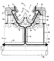
- turbo machine shows schematically and not to scale the only figure through a section of a longitudinal section a double-flow medium pressure steam turbine.
- the section of a turbomachine shown in the figure 1 shows a longitudinal section through a double-flow medium-pressure steam turbine a steam turbine plant.
- 15 of the turbomachine is one along one Main axis 2 extending blade carrier 11 shown. This is made from a plurality of rotor disks 29, only one of them is shown for the sake of clarity is.
- a tie rod 28 Through the rotor disk 29 is along the center the main axis 2, a tie rod 28, which the rotor disks assembles to the blade carrier 11.
- the blade carrier 11 can also be made as one be made in one piece existing turbine shaft.
- the housing 15 is an inflow region 3 for action fluid 4 formed, which is essentially along an inflow axis 17 extends perpendicular to the main axis 2.
- a cooling fluid supply 8 provided.
- This feed 8 goes into one respective guide blade 6 of the first guide blade row 16 about.
- the first row of guide vanes 16 also serves as a holder 22 for an annular shielding element 19.
- This Shielding element 19 is arched into the inflow region 3 and thus causes a redirection of the action fluid 4 as well as a shield of the blade carrier 11 (Turbine rotor) compared to this action fluid 4. From the Guide vane 6 guides the feed 8 into the shielding element 19 in.
- a barrier fluid line 14 provided by the Annular gap 27 open into a blade carrier area 26, which is directly opposite a moving blade 6a. hereby there is a flow of the cooling fluid 5 in the between the blade carrier region 26 and the guide blade 6a Gap in it.
- the cooling fluid 5 has additional there the effect of a barrier fluid through which a flow of the action fluid 4 prevented through this gap, at least significantly reduced. Let her through the gap losses in a non-contact Seal and thus increase the efficiency of the steam turbine.
- cooling fluid lines through which cooling fluid 5 can flow 14 are provided in the housing 15 and connect the Feed 8 in the area of the first row of guide vanes 16 a housing area 25, which is directly a blade 7 is opposite. This is in addition to a cooling also a seal of this gap by the now additionally given cooling fluid 5 acting as a barrier fluid.
- the invention is characterized by a cooling of preferably several components of a turbomachine, the on an inflow area for a hot action fluid, in particular Limit steam above 550 ° C.
- the cooling takes place by introducing a cooling fluid, in particular process steam a steam turbine system or cooling air, through a supply, which in a near-surface area, the inflow area facing part of the housing is arranged. From there the cooling air through the first row of guide vanes into a shielding element led, which attached to the guide vane row is.
- Both in the housing, the guide vane, and the Shielding element can be provided branch lines flow into the inflow area and thus film cooling the enable each component.
- Barrier fluid lines branching off from the supply additionally as a barrier fluid in a gap between a rotating one Component (blade, blade carrier) and one fixed components (guide vane, housing) are guided, creating the seal of a non-contact seal is significantly improved.
Landscapes
- Engineering & Computer Science (AREA)
- Mechanical Engineering (AREA)
- General Engineering & Computer Science (AREA)
- Physics & Mathematics (AREA)
- Fluid Mechanics (AREA)
- Turbine Rotor Nozzle Sealing (AREA)
- Motor Or Generator Cooling System (AREA)
- Heat Treatment Of Articles (AREA)
Claims (9)
- Turbomachine, notamment turbine à vapeur, comprenant un carter (15) et une zone (3) d'entrée de fluide et (4) d'action formée au moins en partie par le carter (15), une admission (8) d'un fluide (5) de refroidissement, un support (11) d'aubes mobiles disposé dans le carter (15) et s'étendant le long d'un axe (2) principal et un élément (19) qui forme écran, qui est disposé dans la zone (3) d'entrée, qui sert à protéger le support (11) d'aubes mobiles du fluide (4) d'action et qui est fixé par une pièce (22) de maintien au carter (15), l'admission (8) étant guidée par la pièce (22) de maintien, un espace (9) intermédiaire étant formé entre l'élément (19) formant écran et le support (11) d'aubes mobiles, espace intermédiaire dans lequel débouche l'admission (8),
caractérisée en ce que la pièce (22) de fixation est constituée sous la forme d'une première aube (6) directrice. - Turbomachine (1) suivant la revendication 1, dans laquelle l'admission passe dans le carter (15) au moins en partie alentour de la zone (3) d'entrée pour son refroidissement.
- Turbomachine (1 ) suivant l'une des revendications précédentes, dans laquelle la pièce (22) de maintien a au moins un conduit (23) de dérivation qui communique avec l'admission (8) et qui débouche dans la zone (3) d'entrée.
- Turbomachine (1) suivant l'une des revendications précédentes, dans laquelle il est prévu dans l'élément (19) formant écran au moins un conduit (24) de dérivation qui communique avec l'admission (8) et qui débouche dans la zone (3) d'entrée.
- Turbomachine (1) suivant l'une des revendications précédentes, dans laquelle un conduit (13) pour du fluide de refroidissement va de l'espace (9) intermédiaire au support (11) d'aubes mobiles.
- Turbomachine (1) suivant la revendication 5, dans laquelle le support (11) d'aubes mobiles a au moins deux disques (29) de rotor qui sont reliés entre eux par un tirant (28), le conduit (13) de fluide de refroidissement débouchant dans un espace (27) annulaire entre un disque (29) de rotor et un tirant (28).
- Turbomachine (1) suivant l'une des revendications précédentes, dans laquelle l'élément (19) formant écran est constitué pour conduire un courant de fluide et/ou pour dévier du fluide en direction de l'axe (2) principal.
- Turbomachine (1) suivant l'une des revendications précédentes, dans laquelle il est prévu au moins un conduit (14) pour du fluide d'arrêt, qui communique avec l'admission (8) et qui débouche dans une zone (25) du carter opposée à une aube (7) mobile ou dans une zone (26) d'une aube mobile opposée à une aube (6a) directrice.
- Turbomachine (1) suivant l'une des revendications précédentes, qui est une turbine (15) à vapeur moyenne pression à deux flux.
Applications Claiming Priority (3)
| Application Number | Priority Date | Filing Date | Title |
|---|---|---|---|
| DE19624805 | 1996-06-21 | ||
| DE19624805 | 1996-06-21 | ||
| PCT/DE1997/001162 WO1997049900A1 (fr) | 1996-06-21 | 1997-06-09 | Turbomachine et procede de refroidissement d'une turbomachine |
Publications (2)
| Publication Number | Publication Date |
|---|---|
| EP0906493A1 EP0906493A1 (fr) | 1999-04-07 |
| EP0906493B1 true EP0906493B1 (fr) | 2003-08-20 |
Family
ID=7797593
Family Applications (2)
| Application Number | Title | Priority Date | Filing Date |
|---|---|---|---|
| EP97923804A Expired - Lifetime EP0906494B1 (fr) | 1996-06-21 | 1997-05-12 | Arbre de turbine et procede de refroidissement d'un arbre de turbine |
| EP97928113A Expired - Lifetime EP0906493B1 (fr) | 1996-06-21 | 1997-06-09 | Turbomachine et procede de refroidissement d'une turbomachine |
Family Applications Before (1)
| Application Number | Title | Priority Date | Filing Date |
|---|---|---|---|
| EP97923804A Expired - Lifetime EP0906494B1 (fr) | 1996-06-21 | 1997-05-12 | Arbre de turbine et procede de refroidissement d'un arbre de turbine |
Country Status (12)
| Country | Link |
|---|---|
| US (2) | US6102654A (fr) |
| EP (2) | EP0906494B1 (fr) |
| JP (2) | JP3943136B2 (fr) |
| KR (2) | KR20000022066A (fr) |
| CN (2) | CN1106496C (fr) |
| AT (2) | ATE230065T1 (fr) |
| CZ (2) | CZ423498A3 (fr) |
| DE (2) | DE59709016D1 (fr) |
| ES (1) | ES2206724T3 (fr) |
| PL (2) | PL330755A1 (fr) |
| RU (2) | RU2182976C2 (fr) |
| WO (2) | WO1997049901A1 (fr) |
Families Citing this family (42)
| Publication number | Priority date | Publication date | Assignee | Title |
|---|---|---|---|---|
| JP3443102B2 (ja) | 2001-03-23 | 2003-09-02 | 山一電機株式会社 | カードコネクタ |
| EP1452688A1 (fr) | 2003-02-05 | 2004-09-01 | Siemens Aktiengesellschaft | Rotor pour une turbine à vapeur, procédé et utilisation de refroidissement d'un tel rotor |
| EP1445427A1 (fr) | 2003-02-05 | 2004-08-11 | Siemens Aktiengesellschaft | Turbine à vapeur et procédé d'opération d'une turbine à vapeur |
| US6854954B2 (en) * | 2003-03-03 | 2005-02-15 | General Electric Company | Methods and apparatus for assembling turbine engines |
| EP1473442B1 (fr) * | 2003-04-30 | 2014-04-23 | Kabushiki Kaisha Toshiba | Turbine à vapeur, centrale à vapeur et méthode pour opérer une turbine à vapeur dans une centrale à vapeur |
| CN1573018B (zh) * | 2003-05-20 | 2010-09-15 | 株式会社东芝 | 蒸汽涡轮机 |
| JP4509664B2 (ja) * | 2003-07-30 | 2010-07-21 | 株式会社東芝 | 蒸気タービン発電設備 |
| DE10355738A1 (de) * | 2003-11-28 | 2005-06-16 | Alstom Technology Ltd | Rotor für eine Turbine |
| EP1624155A1 (fr) | 2004-08-02 | 2006-02-08 | Siemens Aktiengesellschaft | Turbine à vapeur et procédé d'opération d'une turbine à vapeur |
| US7357618B2 (en) * | 2005-05-25 | 2008-04-15 | General Electric Company | Flow splitter for steam turbines |
| US20070065273A1 (en) | 2005-09-22 | 2007-03-22 | General Electric Company | Methods and apparatus for double flow turbine first stage cooling |
| EP1785586B1 (fr) * | 2005-10-20 | 2014-05-07 | Siemens Aktiengesellschaft | Rotor d'une turbomachine |
| EP1780376A1 (fr) * | 2005-10-31 | 2007-05-02 | Siemens Aktiengesellschaft | Turbine à vapeur |
| US7322789B2 (en) * | 2005-11-07 | 2008-01-29 | General Electric Company | Methods and apparatus for channeling steam flow to turbines |
| US7537430B2 (en) * | 2005-11-11 | 2009-05-26 | General Electric Company | Stacked reaction steam turbine rotor assembly |
| US7874795B2 (en) * | 2006-09-11 | 2011-01-25 | General Electric Company | Turbine nozzle assemblies |
| EP1911933A1 (fr) * | 2006-10-09 | 2008-04-16 | Siemens Aktiengesellschaft | Rotor pour une turbomachine |
| US7670108B2 (en) * | 2006-11-21 | 2010-03-02 | Siemens Energy, Inc. | Air seal unit adapted to be positioned adjacent blade structure in a gas turbine |
| US8257015B2 (en) * | 2008-02-14 | 2012-09-04 | General Electric Company | Apparatus for cooling rotary components within a steam turbine |
| US8113764B2 (en) | 2008-03-20 | 2012-02-14 | General Electric Company | Steam turbine and a method of determining leakage within a steam turbine |
| US8096748B2 (en) * | 2008-05-15 | 2012-01-17 | General Electric Company | Apparatus and method for double flow turbine first stage cooling |
| US8087871B2 (en) * | 2009-05-28 | 2012-01-03 | General Electric Company | Turbomachine compressor wheel member |
| US20110158819A1 (en) * | 2009-12-30 | 2011-06-30 | General Electric Company | Internal reaction steam turbine cooling arrangement |
| US8657562B2 (en) * | 2010-11-19 | 2014-02-25 | General Electric Company | Self-aligning flow splitter for steam turbine |
| RU2539404C2 (ru) | 2010-11-29 | 2015-01-20 | Альстом Текнолоджи Лтд | Осевая газовая турбина |
| EP2503101A2 (fr) * | 2011-03-22 | 2012-09-26 | General Electric Company | Système de régulation d'un liquide de refroidissement dans une turbomachine |
| US8888436B2 (en) | 2011-06-23 | 2014-11-18 | General Electric Company | Systems and methods for cooling high pressure and intermediate pressure sections of a steam turbine |
| US8899909B2 (en) | 2011-06-27 | 2014-12-02 | General Electric Company | Systems and methods for steam turbine wheel space cooling |
| US8888437B2 (en) | 2011-10-19 | 2014-11-18 | General Electric Company | Dual-flow steam turbine with steam cooling |
| US20130259662A1 (en) * | 2012-03-29 | 2013-10-03 | General Electric Company | Rotor and wheel cooling assembly for a steam turbine system |
| US20130323009A1 (en) * | 2012-05-31 | 2013-12-05 | Mark Kevin Bowen | Methods and apparatus for cooling rotary components within a steam turbine |
| CN103603694B (zh) * | 2013-12-04 | 2015-07-29 | 上海金通灵动力科技有限公司 | 一种降低汽轮机主轴轴承处工作温度的结构 |
| EP2918788A1 (fr) * | 2014-03-12 | 2015-09-16 | Siemens Aktiengesellschaft | Procédé de refroidissement d'une turbine à vapeur |
| US10208609B2 (en) | 2014-06-09 | 2019-02-19 | General Electric Company | Turbine and methods of assembling the same |
| EP3009597A1 (fr) * | 2014-10-15 | 2016-04-20 | Siemens Aktiengesellschaft | Refroidissement contrôlé d'arbres de turbines |
| EP3056663A1 (fr) * | 2015-02-10 | 2016-08-17 | Siemens Aktiengesellschaft | Turbine à vapeur axiale, en particulier dans une construction à double flux |
| RU2665797C1 (ru) * | 2016-07-04 | 2018-09-04 | Публичное акционерное общество "ОДК-Уфимское моторостроительное производственное объединение" (ПАО "ОДК-УМПО") | Способ и устройство охлаждения вала авиационного газотурбинного двигателя |
| CN109236379A (zh) * | 2018-09-11 | 2019-01-18 | 上海发电设备成套设计研究院有限责任公司 | 一种内部蒸汽冷却的高参数汽轮机的双流高温转子 |
| CN109236378A (zh) * | 2018-09-11 | 2019-01-18 | 上海发电设备成套设计研究院有限责任公司 | 一种内部蒸汽冷却的高参数汽轮机的单流高温转子 |
| JP7271408B2 (ja) * | 2019-12-10 | 2023-05-11 | 東芝エネルギーシステムズ株式会社 | タービンロータ |
| CN111520195B (zh) * | 2020-04-03 | 2022-05-10 | 东方电气集团东方汽轮机有限公司 | 一种汽轮机低压进汽室导流结构及其参数设计方法 |
| CN113914946A (zh) * | 2021-10-29 | 2022-01-11 | 华能上海燃机发电有限责任公司 | 一种联合循环机组的透平端轴承热控线缆冷却装置 |
Family Cites Families (25)
| Publication number | Priority date | Publication date | Assignee | Title |
|---|---|---|---|---|
| US2657901A (en) * | 1945-06-08 | 1953-11-03 | Power Jets Res & Dev Ltd | Construction of turbine rotors |
| CH259566A (de) * | 1947-08-09 | 1949-01-31 | Sulzer Ag | Läufer für Kreiselmaschinen, insbesondere Gasturbinen. |
| US2826895A (en) * | 1953-09-03 | 1958-03-18 | Fairchild Engine & Airplane | Bearing cooling system |
| CH430757A (de) * | 1963-01-18 | 1967-02-28 | Siemens Ag | Dampfturbine |
| DE1551210A1 (de) * | 1966-06-18 | 1970-01-15 | Siemens Ag | Scheibenlaeufer fuer Turbinen,die zum Antrieb von Wechselstromgeneratoren dienen |
| JPS5650084B2 (fr) * | 1972-04-26 | 1981-11-26 | ||
| US4242041A (en) * | 1979-01-15 | 1980-12-30 | Westinghouse Electric Corp. | Rotor cooling for double axial flow turbines |
| DE3071161D1 (en) * | 1980-05-19 | 1985-11-14 | Bbc Brown Boveri & Cie | Cooled turbine stator |
| US4312624A (en) * | 1980-11-10 | 1982-01-26 | United Technologies Corporation | Air cooled hollow vane construction |
| JPS57188702A (en) * | 1981-05-15 | 1982-11-19 | Toshiba Corp | Steam turbine rotor cooling method |
| JPS5830405A (ja) * | 1981-08-19 | 1983-02-22 | Hitachi Ltd | 軸流機械のロ−タ取付装置 |
| JPS58155203A (ja) * | 1982-03-12 | 1983-09-14 | Toshiba Corp | 蒸気タ−ビン |
| DE3209506A1 (de) * | 1982-03-16 | 1983-09-22 | Kraftwerk Union AG, 4330 Mülheim | Axial beaufschlagte dampfturbine, insbesondere in zweiflutiger ausfuehrung |
| JPS59153901A (ja) * | 1983-02-21 | 1984-09-01 | Fuji Electric Co Ltd | 蒸気タ−ビンロ−タの冷却装置 |
| JPS59155503A (ja) * | 1983-02-24 | 1984-09-04 | Toshiba Corp | 軸流タ−ビンのロ−タ冷却装置 |
| DE3424139C2 (de) * | 1984-06-30 | 1996-02-22 | Bbc Brown Boveri & Cie | Gasturbinenrotor |
| US5020318A (en) * | 1987-11-05 | 1991-06-04 | General Electric Company | Aircraft engine frame construction |
| JP2756117B2 (ja) * | 1987-11-25 | 1998-05-25 | 株式会社日立製作所 | ガスタービンロータ |
| SU1537840A1 (ru) * | 1988-04-11 | 1990-01-23 | Научно-Производственное Объединение По Исследованию И Проектированию Энергетического Оборудования Им.И.И.Ползунова | Устройство дл охлаждени ротора паровой турбины |
| SU1673734A1 (ru) * | 1989-05-10 | 1991-08-30 | Научно-Производственное Объединение По Исследованию И Проектированию Энергетического Оборудования Им.И.И.Ползунова | Устройство дл охлаждени ротора паровой турбины |
| US5054996A (en) * | 1990-07-27 | 1991-10-08 | General Electric Company | Thermal linear actuator for rotor air flow control in a gas turbine |
| US5224818A (en) * | 1991-11-01 | 1993-07-06 | General Electric Company | Air transfer bushing |
| US5292227A (en) * | 1992-12-10 | 1994-03-08 | General Electric Company | Turbine frame |
| JPH06330702A (ja) * | 1993-05-26 | 1994-11-29 | Ishikawajima Harima Heavy Ind Co Ltd | タービンディスク |
| DE4324034A1 (de) * | 1993-07-17 | 1995-01-19 | Abb Management Ag | Gasturbine mit gekühltem Rotor |
-
1997
- 1997-05-12 KR KR1019980710469A patent/KR20000022066A/ko not_active Ceased
- 1997-05-12 PL PL97330755A patent/PL330755A1/xx unknown
- 1997-05-12 JP JP50204798A patent/JP3943136B2/ja not_active Expired - Fee Related
- 1997-05-12 CN CN97197351A patent/CN1106496C/zh not_active Expired - Lifetime
- 1997-05-12 RU RU99101061/06A patent/RU2182976C2/ru active
- 1997-05-12 CZ CZ984234A patent/CZ423498A3/cs unknown
- 1997-05-12 DE DE59709016T patent/DE59709016D1/de not_active Expired - Lifetime
- 1997-05-12 WO PCT/DE1997/000953 patent/WO1997049901A1/fr not_active Ceased
- 1997-05-12 EP EP97923804A patent/EP0906494B1/fr not_active Expired - Lifetime
- 1997-05-12 AT AT97923804T patent/ATE230065T1/de not_active IP Right Cessation
- 1997-06-09 DE DE59710625T patent/DE59710625D1/de not_active Expired - Lifetime
- 1997-06-09 AT AT97928113T patent/ATE247766T1/de not_active IP Right Cessation
- 1997-06-09 CZ CZ984227A patent/CZ422798A3/cs unknown
- 1997-06-09 PL PL97330425A patent/PL330425A1/xx unknown
- 1997-06-09 WO PCT/DE1997/001162 patent/WO1997049900A1/fr not_active Ceased
- 1997-06-09 KR KR1019980710468A patent/KR20000022065A/ko not_active Ceased
- 1997-06-09 CN CN97197084A patent/CN1100193C/zh not_active Expired - Fee Related
- 1997-06-09 JP JP50206598A patent/JP3939762B2/ja not_active Expired - Fee Related
- 1997-06-09 EP EP97928113A patent/EP0906493B1/fr not_active Expired - Lifetime
- 1997-06-09 RU RU99101084/06A patent/RU2182975C2/ru not_active IP Right Cessation
- 1997-06-09 ES ES97928113T patent/ES2206724T3/es not_active Expired - Lifetime
-
1998
- 1998-12-21 US US09/217,855 patent/US6102654A/en not_active Expired - Lifetime
- 1998-12-21 US US09/217,853 patent/US6048169A/en not_active Expired - Lifetime
Also Published As
| Publication number | Publication date |
|---|---|
| RU2182975C2 (ru) | 2002-05-27 |
| JP2000512706A (ja) | 2000-09-26 |
| JP3943136B2 (ja) | 2007-07-11 |
| EP0906494A1 (fr) | 1999-04-07 |
| CZ422798A3 (cs) | 1999-04-14 |
| CN1227619A (zh) | 1999-09-01 |
| EP0906494B1 (fr) | 2002-12-18 |
| US6048169A (en) | 2000-04-11 |
| PL330755A1 (en) | 1999-05-24 |
| PL330425A1 (en) | 1999-05-10 |
| ATE230065T1 (de) | 2003-01-15 |
| US6102654A (en) | 2000-08-15 |
| EP0906493A1 (fr) | 1999-04-07 |
| WO1997049900A1 (fr) | 1997-12-31 |
| CN1106496C (zh) | 2003-04-23 |
| JP3939762B2 (ja) | 2007-07-04 |
| CZ423498A3 (cs) | 1999-04-14 |
| CN1100193C (zh) | 2003-01-29 |
| CN1228134A (zh) | 1999-09-08 |
| ES2206724T3 (es) | 2004-05-16 |
| KR20000022065A (ko) | 2000-04-25 |
| WO1997049901A1 (fr) | 1997-12-31 |
| RU2182976C2 (ru) | 2002-05-27 |
| DE59710625D1 (de) | 2003-09-25 |
| JP2000512708A (ja) | 2000-09-26 |
| KR20000022066A (ko) | 2000-04-25 |
| DE59709016D1 (de) | 2003-01-30 |
| ATE247766T1 (de) | 2003-09-15 |
Similar Documents
| Publication | Publication Date | Title |
|---|---|---|
| EP0906493B1 (fr) | Turbomachine et procede de refroidissement d'une turbomachine | |
| DE19620828C1 (de) | Turbinenwelle sowie Verfahren zur Kühlung einer Turbinenwelle | |
| EP1505254B1 (fr) | Turbine à gaz et méthode pour la refroidir | |
| EP2179143B1 (fr) | Refroidissement de fente entre une paroi de chambre de combustion et une paroi de turbine d'une installation de turbine à gaz | |
| EP1111189B1 (fr) | Chemin d'air de refroidissement pour le rotor d'une turbine à gaz | |
| EP2818724B1 (fr) | Turbomachine et procédé | |
| EP0953099B1 (fr) | Turbine a vapeur | |
| EP0122872A1 (fr) | Turbine de vapeur de moyenne pression pour une installation de vapeur de haute température avec réchauffage intermédiaire | |
| EP2092164B1 (fr) | Turbo machine, en particulier turbine à gaz | |
| EP1245806A1 (fr) | Aube de turbine refroidie | |
| EP3130748A1 (fr) | Refroidissement de rotor pour une turbine a vapeur | |
| EP3095957B1 (fr) | Disque de rotor pour compresseur | |
| DE10392802B4 (de) | Dampfturbine | |
| WO2001086121A1 (fr) | Procede pour le refroidissement d'un arbre dans un segment d'expansion haute pression d'une turbine a vapeur | |
| DE102010012583A1 (de) | Verfahren zum Betrieb einer Dampfturbine mit einem Impulsrotor sowie Dampfturbine zur Durchführung des Verfahrens | |
| EP3155226B1 (fr) | Turbine à vapeur et procédé de fonctionnement d'une turbine à vapeur | |
| EP1456507B1 (fr) | Agencement d'etancheite pour composants d'une turbomachine | |
| DE1941873A1 (de) | Gaturbinentriebwerk | |
| EP2324208B1 (fr) | Support d'aube directrice de turbine pour une turbine à gaz | |
| DE3424139A1 (de) | Rotor, im wesentlichen bestehend aus einer trommel und einer zu kuehlenden scheibe | |
| EP1734292A1 (fr) | Dispositif d'étanchéité pour une turbomachine | |
| DE102012109719A1 (de) | Zweiflutige Dampfturbine mit Dampfkühlung | |
| EP1676977A1 (fr) | Turbine à gaz comprenant une tuyère de tourbillonnement et procédé de fonctionnement d'une telle turbine | |
| DE3817986A1 (de) | Gasturbinenanlage mit zwischenkuehlung | |
| DE102012222379B4 (de) | Dichtelement und Strömungsmaschine |
Legal Events
| Date | Code | Title | Description |
|---|---|---|---|
| PUAI | Public reference made under article 153(3) epc to a published international application that has entered the european phase |
Free format text: ORIGINAL CODE: 0009012 |
|
| 17P | Request for examination filed |
Effective date: 19981204 |
|
| AK | Designated contracting states |
Kind code of ref document: A1 Designated state(s): AT CH DE ES FR GB IT LI NL SE |
|
| 17Q | First examination report despatched |
Effective date: 20011205 |
|
| GRAH | Despatch of communication of intention to grant a patent |
Free format text: ORIGINAL CODE: EPIDOS IGRA |
|
| GRAH | Despatch of communication of intention to grant a patent |
Free format text: ORIGINAL CODE: EPIDOS IGRA |
|
| GRAA | (expected) grant |
Free format text: ORIGINAL CODE: 0009210 |
|
| AK | Designated contracting states |
Designated state(s): AT CH DE ES FR GB IT LI NL SE |
|
| PG25 | Lapsed in a contracting state [announced via postgrant information from national office to epo] |
Ref country code: NL Free format text: LAPSE BECAUSE OF FAILURE TO SUBMIT A TRANSLATION OF THE DESCRIPTION OR TO PAY THE FEE WITHIN THE PRESCRIBED TIME-LIMIT Effective date: 20030820 |
|
| REG | Reference to a national code |
Ref country code: GB Ref legal event code: FG4D Free format text: NOT ENGLISH |
|
| REG | Reference to a national code |
Ref country code: CH Ref legal event code: EP |
|
| REG | Reference to a national code |
Ref country code: CH Ref legal event code: NV Representative=s name: SERVOPATENT GMBH |
|
| REF | Corresponds to: |
Ref document number: 59710625 Country of ref document: DE Date of ref document: 20030925 Kind code of ref document: P |
|
| PG25 | Lapsed in a contracting state [announced via postgrant information from national office to epo] |
Ref country code: SE Free format text: LAPSE BECAUSE OF FAILURE TO SUBMIT A TRANSLATION OF THE DESCRIPTION OR TO PAY THE FEE WITHIN THE PRESCRIBED TIME-LIMIT Effective date: 20031120 |
|
| GBT | Gb: translation of ep patent filed (gb section 77(6)(a)/1977) |
Effective date: 20031204 |
|
| NLV1 | Nl: lapsed or annulled due to failure to fulfill the requirements of art. 29p and 29m of the patents act | ||
| REG | Reference to a national code |
Ref country code: ES Ref legal event code: FG2A Ref document number: 2206724 Country of ref document: ES Kind code of ref document: T3 |
|
| ET | Fr: translation filed | ||
| PG25 | Lapsed in a contracting state [announced via postgrant information from national office to epo] |
Ref country code: AT Free format text: LAPSE BECAUSE OF NON-PAYMENT OF DUE FEES Effective date: 20040609 |
|
| PLBE | No opposition filed within time limit |
Free format text: ORIGINAL CODE: 0009261 |
|
| STAA | Information on the status of an ep patent application or granted ep patent |
Free format text: STATUS: NO OPPOSITION FILED WITHIN TIME LIMIT |
|
| 26N | No opposition filed |
Effective date: 20040524 |
|
| REG | Reference to a national code |
Ref country code: CH Ref legal event code: PCAR Free format text: SIEMENS SCHWEIZ AG;INTELLECTUAL PROPERTY FREILAGERSTRASSE 40;8047 ZUERICH (CH) |
|
| PGFP | Annual fee paid to national office [announced via postgrant information from national office to epo] |
Ref country code: IT Payment date: 20120626 Year of fee payment: 16 |
|
| PGFP | Annual fee paid to national office [announced via postgrant information from national office to epo] |
Ref country code: GB Payment date: 20130610 Year of fee payment: 17 |
|
| PGFP | Annual fee paid to national office [announced via postgrant information from national office to epo] |
Ref country code: FR Payment date: 20130703 Year of fee payment: 17 |
|
| PGFP | Annual fee paid to national office [announced via postgrant information from national office to epo] |
Ref country code: CH Payment date: 20130909 Year of fee payment: 17 Ref country code: ES Payment date: 20130711 Year of fee payment: 17 Ref country code: DE Payment date: 20130819 Year of fee payment: 17 |
|
| PG25 | Lapsed in a contracting state [announced via postgrant information from national office to epo] |
Ref country code: IT Free format text: LAPSE BECAUSE OF NON-PAYMENT OF DUE FEES Effective date: 20130609 |
|
| REG | Reference to a national code |
Ref country code: DE Ref legal event code: R119 Ref document number: 59710625 Country of ref document: DE |
|
| REG | Reference to a national code |
Ref country code: CH Ref legal event code: PL |
|
| GBPC | Gb: european patent ceased through non-payment of renewal fee |
Effective date: 20140609 |
|
| REG | Reference to a national code |
Ref country code: FR Ref legal event code: ST Effective date: 20150227 |
|
| REG | Reference to a national code |
Ref country code: DE Ref legal event code: R119 Ref document number: 59710625 Country of ref document: DE Effective date: 20150101 |
|
| PG25 | Lapsed in a contracting state [announced via postgrant information from national office to epo] |
Ref country code: CH Free format text: LAPSE BECAUSE OF NON-PAYMENT OF DUE FEES Effective date: 20140630 Ref country code: DE Free format text: LAPSE BECAUSE OF NON-PAYMENT OF DUE FEES Effective date: 20150101 Ref country code: LI Free format text: LAPSE BECAUSE OF NON-PAYMENT OF DUE FEES Effective date: 20140630 |
|
| PG25 | Lapsed in a contracting state [announced via postgrant information from national office to epo] |
Ref country code: FR Free format text: LAPSE BECAUSE OF NON-PAYMENT OF DUE FEES Effective date: 20140630 Ref country code: GB Free format text: LAPSE BECAUSE OF NON-PAYMENT OF DUE FEES Effective date: 20140609 |
|
| REG | Reference to a national code |
Ref country code: ES Ref legal event code: FD2A Effective date: 20150729 |
|
| PG25 | Lapsed in a contracting state [announced via postgrant information from national office to epo] |
Ref country code: ES Free format text: LAPSE BECAUSE OF NON-PAYMENT OF DUE FEES Effective date: 20140610 |