EP0906493B1 - Turbomachine and process for cooling a turbomachine - Google Patents
Turbomachine and process for cooling a turbomachine Download PDFInfo
- Publication number
- EP0906493B1 EP0906493B1 EP97928113A EP97928113A EP0906493B1 EP 0906493 B1 EP0906493 B1 EP 0906493B1 EP 97928113 A EP97928113 A EP 97928113A EP 97928113 A EP97928113 A EP 97928113A EP 0906493 B1 EP0906493 B1 EP 0906493B1
- Authority
- EP
- European Patent Office
- Prior art keywords
- cooling
- turbomachine
- rotor
- fluid
- feed
- Prior art date
- Legal status (The legal status is an assumption and is not a legal conclusion. Google has not performed a legal analysis and makes no representation as to the accuracy of the status listed.)
- Expired - Lifetime
Links
- 238000001816 cooling Methods 0.000 title claims abstract description 35
- 238000000034 method Methods 0.000 title abstract description 11
- 239000012530 fluid Substances 0.000 claims description 31
- 239000012809 cooling fluid Substances 0.000 claims description 29
- 230000004888 barrier function Effects 0.000 description 6
- 230000000694 effects Effects 0.000 description 2
- 239000000463 material Substances 0.000 description 2
- 229910000669 Chrome steel Inorganic materials 0.000 description 1
- 239000000969 carrier Substances 0.000 description 1
- 229910000734 martensite Inorganic materials 0.000 description 1
Images
Classifications
-
- F—MECHANICAL ENGINEERING; LIGHTING; HEATING; WEAPONS; BLASTING
- F01—MACHINES OR ENGINES IN GENERAL; ENGINE PLANTS IN GENERAL; STEAM ENGINES
- F01D—NON-POSITIVE DISPLACEMENT MACHINES OR ENGINES, e.g. STEAM TURBINES
- F01D9/00—Stators
- F01D9/06—Fluid supply conduits to nozzles or the like
- F01D9/065—Fluid supply or removal conduits traversing the working fluid flow, e.g. for lubrication-, cooling-, or sealing fluids
-
- F—MECHANICAL ENGINEERING; LIGHTING; HEATING; WEAPONS; BLASTING
- F01—MACHINES OR ENGINES IN GENERAL; ENGINE PLANTS IN GENERAL; STEAM ENGINES
- F01D—NON-POSITIVE DISPLACEMENT MACHINES OR ENGINES, e.g. STEAM TURBINES
- F01D3/00—Machines or engines with axial-thrust balancing effected by working-fluid
- F01D3/02—Machines or engines with axial-thrust balancing effected by working-fluid characterised by having one fluid flow in one axial direction and another fluid flow in the opposite direction
-
- F—MECHANICAL ENGINEERING; LIGHTING; HEATING; WEAPONS; BLASTING
- F01—MACHINES OR ENGINES IN GENERAL; ENGINE PLANTS IN GENERAL; STEAM ENGINES
- F01D—NON-POSITIVE DISPLACEMENT MACHINES OR ENGINES, e.g. STEAM TURBINES
- F01D5/00—Blades; Blade-carrying members; Heating, heat-insulating, cooling or antivibration means on the blades or the members
- F01D5/02—Blade-carrying members, e.g. rotors
- F01D5/08—Heating, heat-insulating or cooling means
Definitions
- the invention relates to a turbomachine, in particular one Steam turbine, with a housing and at least partially inflow area for action fluid formed by the housing and a method for cooling at least one Inflow area of a component assigned to a turbomachine.
- the object of the invention is to provide a turbomachine, which in a thermally highly stressed area, in particular an inflow area for action fluid, is coolable.
- Another object of the invention is a method for cooling at least one adjacent to the inflow area Specify component of the turbomachine.
- a turbomachine in particular a steam turbine
- task accomplished by such a which is a housing with an at least partially the housing has an inflow area for action fluid
- a supply for a cooling fluid in the housing is provided, by cooling the housing, in particular the housing walls adjacent to the inflow area, is feasible.
- the cooling fluid can process steam from a steam turbine plant with several partial turbines, act separate cooling steam or cooling air.
- the turbomachine preferably has a shielding element adjacent to the inflow area which is along a major axis in the housing extending blade carrier opposite the action fluid shielded and attached to the housing by a bracket is, the feed through the holder into the shielding element is introduced.
- the shielding element can be on multiple positions via a bracket or several Brackets to be connected to the housing. It will achieved several cooling effects at the same time, namely one Cooling the housing to those adjacent to the inflow area Walls, cooling the bracket, cooling the Shielding element and thus also cooling of the rotor blade carrier.
- the holder is preferably in at least one direction seen the first guide vane row integrated into the action fluid.
- a branch line preferably a plurality of branch lines are provided, which is (are) connected to the feed and into the inflow area and / or one facing away from the inflow area Side. This will provide additional film cooling of the first row of guide vanes.
- the shielding element preferably also has at least one a branch line, which is connected to the feeder and flows into the inflow area. This leads to film cooling of the shielding element and thus indirectly to one further reduction of the thermal load on the blade carrier.
- the shielding element can also have a Have connected cavity connected, creating an increased Heat transfer in the shielding element towards the Blade carrier is avoided.
- a gap is towards the blade carrier formed, into which the feed opens.
- the gap can thus be filled with cooling fluid, so that heat transfer of the one heated by the action fluid Shielding element is reduced in the blade carrier. Since the shielding element over the bracket with the housing connected, it is spaced from the blade carrier, so that an outflow of the cooling fluid with the between the housing and blade carriers guaranteeing flowing action fluid is. From the gap preferably leads a cooling fluid line, in particular in the form of a radial bore, into the blade carrier. This leads to especially with a blade carrier, made up of two or several rotor disks arranged centrally to each other, by means of a tie rod that runs through appropriate openings are connected to further cooling.
- cooling fluid into one between the Tie rod and the rotor disk formed annulus.
- Turbine shaft possible, in particular in that at least one axial running parallel to the main axis Bore is provided, into which the cooling fluid line opens.
- the turbo machine enables a feed of Cooling fluid through the housing also reduces a leakage flow of action fluid between a gap rotating component (blade, blade carrier) and a fixed component (guide vane, housing) the steam turbine.
- This can cause these so-called gap losses be reduced by appropriate branch lines in the housing or the blade carrier cooling fluid from the supply, the space or the cooling fluid line can be branched off and guided into this gap.
- Such a branch line is therefore preferably from the feeder for Cooling fluid guided so that it is in a gap between the housing and blade or vane and blade carrier empties. The sealability of a non-contact seal between a rotating and a fixed component the turbomachine is thus significantly increased.
- a guidance of cooling fluid is preferably particularly suitable for a turbo machine in which the shielding element for power division and / or for redirecting the action fluid in the direction the main axis is formed.
- the inflow area is preferred for guiding the action fluid in one direction essentially perpendicular to the main axis of the blade carrier educated.
- the turbo machine is preferred a double-flow steam turbine, in particular a medium-pressure steam turbine, in which both a current division and a Redirection of the action fluid takes place. Of course is such cooling even with a single-flow steam turbine possible in their inflow area.
- Process steam from a steam turbine plant as cooling fluid is used over the various branches the entire steam process fed back, the as Cooling fluid used steam when flowing through the feed is heated. Compared to cooling in which the process steam is lost, can also be used Efficiency increase of the steam turbine can be achieved.
- the on a method of cooling one to the inflow area a turbomachine, in particular a steam turbine, adjacent component directed task is solved by that cooling fluid through at least partially the inflow area forming housing, especially in the area of the inflow area and from there a shielding element to reduce the temperature load one in the Housing arranged blade carrier is supplied.
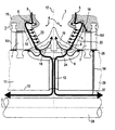
- turbo machine shows schematically and not to scale the only figure through a section of a longitudinal section a double-flow medium pressure steam turbine.
- the section of a turbomachine shown in the figure 1 shows a longitudinal section through a double-flow medium-pressure steam turbine a steam turbine plant.
- 15 of the turbomachine is one along one Main axis 2 extending blade carrier 11 shown. This is made from a plurality of rotor disks 29, only one of them is shown for the sake of clarity is.
- a tie rod 28 Through the rotor disk 29 is along the center the main axis 2, a tie rod 28, which the rotor disks assembles to the blade carrier 11.
- the blade carrier 11 can also be made as one be made in one piece existing turbine shaft.
- the housing 15 is an inflow region 3 for action fluid 4 formed, which is essentially along an inflow axis 17 extends perpendicular to the main axis 2.
- a cooling fluid supply 8 provided.
- This feed 8 goes into one respective guide blade 6 of the first guide blade row 16 about.
- the first row of guide vanes 16 also serves as a holder 22 for an annular shielding element 19.
- This Shielding element 19 is arched into the inflow region 3 and thus causes a redirection of the action fluid 4 as well as a shield of the blade carrier 11 (Turbine rotor) compared to this action fluid 4. From the Guide vane 6 guides the feed 8 into the shielding element 19 in.
- a barrier fluid line 14 provided by the Annular gap 27 open into a blade carrier area 26, which is directly opposite a moving blade 6a. hereby there is a flow of the cooling fluid 5 in the between the blade carrier region 26 and the guide blade 6a Gap in it.
- the cooling fluid 5 has additional there the effect of a barrier fluid through which a flow of the action fluid 4 prevented through this gap, at least significantly reduced. Let her through the gap losses in a non-contact Seal and thus increase the efficiency of the steam turbine.
- cooling fluid lines through which cooling fluid 5 can flow 14 are provided in the housing 15 and connect the Feed 8 in the area of the first row of guide vanes 16 a housing area 25, which is directly a blade 7 is opposite. This is in addition to a cooling also a seal of this gap by the now additionally given cooling fluid 5 acting as a barrier fluid.
- the invention is characterized by a cooling of preferably several components of a turbomachine, the on an inflow area for a hot action fluid, in particular Limit steam above 550 ° C.
- the cooling takes place by introducing a cooling fluid, in particular process steam a steam turbine system or cooling air, through a supply, which in a near-surface area, the inflow area facing part of the housing is arranged. From there the cooling air through the first row of guide vanes into a shielding element led, which attached to the guide vane row is.
- Both in the housing, the guide vane, and the Shielding element can be provided branch lines flow into the inflow area and thus film cooling the enable each component.
- Barrier fluid lines branching off from the supply additionally as a barrier fluid in a gap between a rotating one Component (blade, blade carrier) and one fixed components (guide vane, housing) are guided, creating the seal of a non-contact seal is significantly improved.
Landscapes
- Engineering & Computer Science (AREA)
- Mechanical Engineering (AREA)
- General Engineering & Computer Science (AREA)
- Physics & Mathematics (AREA)
- Fluid Mechanics (AREA)
- Turbine Rotor Nozzle Sealing (AREA)
- Motor Or Generator Cooling System (AREA)
- Heat Treatment Of Articles (AREA)
Abstract
Description
Die Erfindung betrifft eine Turbomaschine, insbesondere eine Dampfturbine, mit einem Gehäuse und einem zumindest teilweise durch das Gehäuse gebildeten Einströmbereich für Aktionsfluid sowie ein Verfahren zur Kühlung,von zumindest einer einem Einströmbereich einer Turbomaschine zugeordneten Komponente.The invention relates to a turbomachine, in particular one Steam turbine, with a housing and at least partially inflow area for action fluid formed by the housing and a method for cooling at least one Inflow area of a component assigned to a turbomachine.
Zur Steigerung des Wirkungsgrades einer Dampfturbine trägt die Verwendung von Dampf mit höheren Drücken und Temperaturen bei, insbesondere sogenannte überkritische Dampfzustände, mit einer Temperatur von beispielsweise über 550 °C. Die Verwendung von Dampf mit einem solchen Dampfzustand stellt erhöhte Anforderungen an eine entsprechend beaufschlagte Dampfturbine, insbesondere an die an den Einströmbereich des Aktionsfluides grenzenden Komponenten der Dampfturbine, wie Gehäusewandung und Turbinenwelle.Contributes to increasing the efficiency of a steam turbine the use of steam at higher pressures and temperatures with, in particular so-called supercritical vapor states, with a temperature of, for example, over 550 ° C. The usage of steam with such a vapor state represents increased Requirements for an appropriately loaded steam turbine, in particular to the inflow area of the action fluid bordering components of the steam turbine, such as the casing wall and turbine shaft.
In dem Artikel "Dampfturbinen für fortgeschrittene Kraftwerkskonzepte mit hohen Dampfzuständen von D. Bergmann, A. Drosdziok und H. Oeynhausen, Siemens Power Journal 1/93, S. 5-10 ist eine Läuferabschirmung mit Drallkühlung beschrieben. Bei der Drallkühlung strömt Dampf durch vier tangentiale Bohrungen in der Läuferabschirmung in Drehrichtung der Turbinenwelle in den Bereich zwischen der Läuferabschirmung und em Läufer, ein. Dabei expandiert der Dampf, die Temperatur sinkt und kühlt dadurch den Läufer. Die Läuferabschirmung ist dampfdicht mit einer Leitschaufelreihe verbunden. Durch die Drallkühlung läßt sich eine Temperaturabsenkung des Läufers in der Umgebung der Läuferabschirmung von etwa 15 K erreichen. Eine nähere Erläuterung dieser Läuferabschirmung, welche die Turbinenwelle mit Abstand umschließt und mit den radial inneren Enden der Leitschaufeln des ersten Leitschaufelkranzes verbunden ist, ist in der EP 0 088 944 B1 beschrieben. In der Läuferabschirmung sind Düsen eingebracht, welche in Drehrichtung der Welle gesehen tangential in den zwischen Welle und Wellenabschirmung gebildeten Ringkanal einmünden. Ein weiteres Beispiel für eine Läuferabschirmung ist der DE 32 09 506 A1 entnehmbar. In the article "Steam Turbines for Advanced Power Plant Concepts with high vapor states by D. Bergmann, A. Drosdziok and H. Oeynhausen, Siemens Power Journal 1/93, p. 5-10 a rotor shield with swirl cooling is described. With swirl cooling, steam flows through four tangential holes in the rotor shield in the direction of rotation of the turbine shaft in the area between the rotor shield and em Runner, a. The steam, the temperature, expands thereby sinking and cooling the runner. The rotor shield is steam-tightly connected to a row of guide vanes. By the swirl cooling can be a temperature reduction of the rotor reach around 15 K in the vicinity of the rotor shield. A more detailed explanation of this rotor shield, which encloses the turbine shaft at a distance and with the radially inner ends of the guide vanes of the first guide vane ring is described in EP 0 088 944 B1. Nozzles are installed in the rotor shield, which seen tangentially in the direction of rotation of the shaft ring channel formed between the shaft and the shaft shield open out. Another example of a rotor shield can be found in DE 32 09 506 A1.
In der schweizer Patentschrift 430 757 ist ein Abschirmelement in einem Einströmbereich einer Dampfturbine beschrieben. Dieses Abschirmelement ist mit einer mittig im Einströmbereich, d.h. in dem Strom des heißen Aktionsdampfes, angeordneten Zuführung verbunden. Diese Zuführung dient der Halterung des Abschirmelementes.In the Swiss patent specification 430 757 there is a shielding element described in an inflow area of a steam turbine. This shielding element is centered in the inflow area, i.e. in the stream of hot action steam Feed connected. This feed serves for the holder of the shielding element.
In der DE 34 06 071 A1 ist eine zweiflutige Dampfturbine beschrieben, welche in einem Einströmbereich für Heißdampf ein Abschirmelement für eine Turbinenwelle aufweist. Dieses Abschirmelement ist über die ersten Leitschaufelreihen mit dem Gehäuse verbunden. Zwischen dem Abschirmelement und der Turbinenwelle ist ein Spalt gebildet. Das Abschirmelement weist in seiner Mitte einen Einlaß für den Heißdampf auf, wobei der in den Spalt einströmende Heißdampf vor der ersten Laufschaufelreihe in die Hauptströmung des Heißdampfes zurückströmt. DE 34 06 071 A1 describes a double-flow steam turbine, which in an inflow area for superheated steam Shielding element for a turbine shaft. This shielding element is about the first rows of vanes with the Housing connected. Between the shielding element and the turbine shaft a gap is formed. The shielding element points in the middle of an inlet for the superheated steam, the Hot steam flowing into the gap in front of the first row of blades flows back into the main flow of superheated steam.
Aufgabe der Erfindung ist,es, eine Turbcmaschine anzugeben, welche in einem thermisch hochbelasteten Bereich, insbesondere einem Einströmbereich für Aktionsfluid, kühlbar ist. Eine weitere Aufgabe der Erfindung liegt darin, ein Verfahren zur Kühlung zumindest einer an den Einströmbereich angrenzenden Komponente der Turbomaschine anzugeben.The object of the invention is to provide a turbomachine, which in a thermally highly stressed area, in particular an inflow area for action fluid, is coolable. Another object of the invention is a method for cooling at least one adjacent to the inflow area Specify component of the turbomachine.
Erfindungsgemäß wird die auf eine Turbomaschine, insbesondere eine Dampfturbine, gerichtete Aufgabe durch eine solche gelöst, welche ein Gehäuse mit einem zumindest teilweise durch das Gehäuse gebildeten Einströmbereich für Aktionsfluid aufweist, wobei eine Zuführung für ein Kühlfluid in dem Gehäuse vorgesehen ist, durch die eine Kühlung des Gehäuses, insbesondere der an den Einströmbereich angrenzenden Gehäusewandungen, durchführbar ist. Durch Ausführung eines Gehäuses mit einer solchen Zuführung für Kühlfluid kann auch bei Einströmung von Aktionsfluid in den Einströmbereich mit Temperaturen von oberhalb 550 °C die Temperatur des Gehäuses deutlich erniedrigt werden, wodurch die Verwendung bekannter Werkstoffe, insbesondere martensitischer Chromstähle, möglich ist oder der Einsatz neuer Werkstoffe auf reduziertem Temperaturniveau ermöglicht wird. Bei dem Kühlfluid kann es sich um Prozeßdampf einer Dampfturbinenanlage mit mehreren Teilturbinen, gesondertem Kühldampf oder Kühlluft handeln.According to the invention, it is applied to a turbomachine, in particular a steam turbine, task accomplished by such a which is a housing with an at least partially the housing has an inflow area for action fluid, a supply for a cooling fluid in the housing is provided, by cooling the housing, in particular the housing walls adjacent to the inflow area, is feasible. By executing a housing with such a supply for cooling fluid can also with inflow of action fluid in the inflow area with temperatures the temperature of the housing clearly above 550 ° C be lowered, thereby reducing the use of known ones Materials, especially martensitic chrome steels, possible or the use of new materials at a reduced temperature level is made possible. The cooling fluid can process steam from a steam turbine plant with several partial turbines, act separate cooling steam or cooling air.
Alternativ oder zusätzlich weist die Turbomaschine vorzugsweise ein an den Einströmbereich angrenzendes Abschirmelement auf, welches einen sich entlang einer Hauptachse in dem Gehäuse erstreckenden Laufschaufelträger gegenüber dem Aktionsfluid abschirmt und durch eine Halterung an dem Gehäuse befestigt ist, wobei die Zuführung durch die Halterung in das Abschirmelement hineingeführt ist. Das Abschirmelement kann an mehreren Stellen über jeweils eine Halterung oder mehrere Halterungen mit dem Gehäuse verbunden sein. Es werden gleichzeitig mehrere Kühlungseffekte erzielt, nämlich eine Kühlung des Gehäuses an den dem Einströmungsbereich angrenzenden Wänden, eine Kühlung der Halterung, eine Kühlung des Abschirmelementes und damit auch eine Kühlung des Laufschaufelträgers. Durch eine sich aus mehreren Teilstrecken zusammensetzende, durch den Strömungsweg des Aktionsfluides hindurchgeführte Zuführung wird mit einer einzigen Kühlfluidströmung eine effektive Kühlung einer Mehrzahl von Komponenten der Turbomaschine erreicht.Alternatively or additionally, the turbomachine preferably has a shielding element adjacent to the inflow area which is along a major axis in the housing extending blade carrier opposite the action fluid shielded and attached to the housing by a bracket is, the feed through the holder into the shielding element is introduced. The shielding element can be on multiple positions via a bracket or several Brackets to be connected to the housing. It will achieved several cooling effects at the same time, namely one Cooling the housing to those adjacent to the inflow area Walls, cooling the bracket, cooling the Shielding element and thus also cooling of the rotor blade carrier. Through a combination of several sections, passed through the flow path of the action fluid Feeding is done with a single flow of cooling fluid effective cooling of a plurality of components the turbomachine is reached.
Vorzugsweise ist die Halterung in zumindest eine in Richtung des Aktionsfluides gesehen erste Leitschaufelreihe integriert. Zur Erhöhung der Kühlung dieser ersten Leitschaufelreihe, d. h. der Halterung, ist eine Abzweigleitung, vorzugsweise eine Mehrzahl von Abzweigleitungen vorgesehen, welche mit der Zuführung verbunden ist (bzw. sind) und in den Einströmbereich und/oder einer dem Einströmbereich abgewandten Seite münden. Hierdurch wird eine zusätzliche Filmkühlung der ersten Leitschaufelreihe erreicht.The holder is preferably in at least one direction seen the first guide vane row integrated into the action fluid. To increase the cooling of this first row of guide vanes, d. H. the bracket, is a branch line, preferably a plurality of branch lines are provided, which is (are) connected to the feed and into the inflow area and / or one facing away from the inflow area Side. This will provide additional film cooling of the first row of guide vanes.
Das Abschirmelement weist vorzugsweise ebenfalls zumindest eine Abzweigleitung auf, die mit der Zuführung verbunden ist und in den Einströmbereich mündet. Dies führt zu einer Filmkühlung des Abschirmelementes und damit mittelbar zu einer weiteren Reduktion der Temperaturbelastung des Laufschaufelträgers. Das Abschirmelement kann zusätzlich einen mit der Zuführung verbundenen Hohlraum aufweisen, wodurch ein erhöhter Wärmeübertrag in dem Abschirmelement in Richtung zu dem Laufschaufelträger hin vermieden wird.The shielding element preferably also has at least one a branch line, which is connected to the feeder and flows into the inflow area. This leads to film cooling of the shielding element and thus indirectly to one further reduction of the thermal load on the blade carrier. The shielding element can also have a Have connected cavity connected, creating an increased Heat transfer in the shielding element towards the Blade carrier is avoided.
Durch das Abschirmelement, welches insbesondere ringförmig ausgeführt ist, wird hin zu dem Laufschaufelträger ein Zwischenraum gebildet, in den die Zuführung mündet. Der Zwischenraum ist somit mit Kühlfluid füllbar, so daß ein Wärmeübertrag von dem durch das Aktionsfluid aufgeheizten Abschirmelement in den Laufschaufelträger vermindert wird. Da das Abschirmelement über die Halterung mit dem Gehäuse verbunden ist, ist es von dem Laufschaufelträger beabstandet, so daß eine Abströmung des Kühlfluides mit dem zwischen Gehäuse und Laufschaufelträger strömenden Aktionsfluides gewährleistet ist. Von dem Zwischenraum führt vorzugsweise eine Kühlfluidleitung, insbesondere als radiale Bohrung ausgebildet, in den Laufschaufelträger hinein. Dies führt vorallem bei einem Laufschaufelträger, gebildet aus zwei oder mehreren zentrisch zueinander angeordneten Läuferscheiben, die mittels eines durch entsprechende Öffnungen geführten Zugankers verbunden sind, zu einer weiteren Kühlung. Hierbei erfolgt eine Einführung von Kühlfluid in einen zwischen dem Zuganker und der Läuferscheibe gebildeten Ringraum. Selbstverständlich ist auch eine Kühlung einer im wesentlichen einstöckigen Turbinenwelle möglich, insbesondere dadurch, daß zumindest eine parallel zur Hauptachse verlaufende axiale Bohrung vorgesehen ist, in die die Kühlfluidleitung mündet.Through the shielding element, which is in particular ring-shaped is carried out, a gap is towards the blade carrier formed, into which the feed opens. The gap can thus be filled with cooling fluid, so that heat transfer of the one heated by the action fluid Shielding element is reduced in the blade carrier. Since the shielding element over the bracket with the housing connected, it is spaced from the blade carrier, so that an outflow of the cooling fluid with the between the housing and blade carriers guaranteeing flowing action fluid is. From the gap preferably leads a cooling fluid line, in particular in the form of a radial bore, into the blade carrier. this leads to especially with a blade carrier, made up of two or several rotor disks arranged centrally to each other, by means of a tie rod that runs through appropriate openings are connected to further cooling. in this connection there is an introduction of cooling fluid into one between the Tie rod and the rotor disk formed annulus. Of course is also a cooling one essentially one story Turbine shaft possible, in particular in that at least one axial running parallel to the main axis Bore is provided, into which the cooling fluid line opens.
Zusätzlich tu einer Kühlung der hochtemperaturbelasteten Komponenten der Turbomaschine ermöglicht eine Zuführung von Kühlfluid durch das Gehäuse hindurch auch eine Verminderung einer Leckströmung von Aktionsfluid zwischen einem Spalt einer rotierenden Komponente (Laufschaufel, Laufschaufelträger) und einer feststehenden Komponente (Leitschaufel, Gehäuse) der Dampfturbine. Diese sogenannten Spaltverluste können dadurch reduziert werden, daß durch entsprechende Abzweigleitungen in dem Gehäuse bzw. dem Laufschaufelträger Kühlfluid aus der Zuführung, dem Zwischenraum oder der Kühlfluidleitung abzweigbar und in diesen Spalt führbar ist. Eine solche Abzweigleitung ist somit vorzugsweise von der Zuführung für Kühlfluid so geführt, daß sie in einem Spalt zwischen Gehäuse und Laufschaufel oder Leitschaufel und Laufschaufelträger mündet. Die Dichtfähigkeit einer berührungslosen Dichtung zwischen einer rotierenden und einer feststehenden Komponente der Turbomaschine wird somit deutlich erhöht. In addition, do cooling of the components exposed to high temperatures the turbo machine enables a feed of Cooling fluid through the housing also reduces a leakage flow of action fluid between a gap rotating component (blade, blade carrier) and a fixed component (guide vane, housing) the steam turbine. This can cause these so-called gap losses be reduced by appropriate branch lines in the housing or the blade carrier cooling fluid from the supply, the space or the cooling fluid line can be branched off and guided into this gap. Such a branch line is therefore preferably from the feeder for Cooling fluid guided so that it is in a gap between the housing and blade or vane and blade carrier empties. The sealability of a non-contact seal between a rotating and a fixed component the turbomachine is thus significantly increased.
Vorzugsweise eignet sich eine Führung von Kühlfluid besonders für eine Turbomaschine bei der das Abschirmelement zur Stromteilung und/oder zur Umlenkung des Aktionsfluides in Richtung der Hauptachse ausgebildet ist. Der Einströmbereich ist vorzugsweise für eine Führung des Aktionsfluides in einer Richtung im wesentlichen senkrecht zur Hauptachse des Laufschaufelträgers ausgebildet. Die Turbomaschine ist vorzugsweise eine zweiflutige Dampfturbine, insbesondere eine Mitteldruck-Dampfturbine, in der sowohl eine Stromteilung als auch eine Umlenkung des Aktionsfluides stattfindet. Selbstverständlich ist eine solche Kühlung auch bei einer einflutigen Dampfturbine in deren Einströmbereich möglich.A guidance of cooling fluid is preferably particularly suitable for a turbo machine in which the shielding element for power division and / or for redirecting the action fluid in the direction the main axis is formed. The inflow area is preferred for guiding the action fluid in one direction essentially perpendicular to the main axis of the blade carrier educated. The turbo machine is preferred a double-flow steam turbine, in particular a medium-pressure steam turbine, in which both a current division and a Redirection of the action fluid takes place. Of course is such cooling even with a single-flow steam turbine possible in their inflow area.
Wird als Kühlfluid Prozeßdampf aus einer Dampfturbinenanlage verwendet, so wird dieser über die verschiedenen Abzweigungen dem gesamten Dampfprozeß wieder zugeführt, wobei der als Kühlfluid verwendete Dampf bei Durchströmen der Zuführung aufgeheizt wird. Gegenüber einer Kühlung, bei der der Prozeßdampf verlorengeht, kann hiermit gegebenenfalls auch eine Wirkungsgraderhöhung der Dampfturbine erreicht werden.Process steam from a steam turbine plant as cooling fluid is used over the various branches the entire steam process fed back, the as Cooling fluid used steam when flowing through the feed is heated. Compared to cooling in which the process steam is lost, can also be used Efficiency increase of the steam turbine can be achieved.
Die auf ein Verfahren zur Kühlung einer an den Einströmbereich einer Turbomaschine, insbesondere einer Dampfturbine, angrenzenden Komponente gerichtete Aufgabe, wird dadurch gelöst, daß Kühlfluid durch ein zumindest teilweise den Einströmbereich bildendes Gehäuse, insbesondere in der Umgebung des Einströmbereiches geleitet und von dort einem Abschirmelement zur Reduktion der Temperaturbelastung eines in dem Gehäuse angeordneten Laufschaufelträgers zugeführt wird.The on a method of cooling one to the inflow area a turbomachine, in particular a steam turbine, adjacent component directed task is solved by that cooling fluid through at least partially the inflow area forming housing, especially in the area of the inflow area and from there a shielding element to reduce the temperature load one in the Housing arranged blade carrier is supplied.
Anhand des in der Zeichnung dargestellten Ausführungsbeispieles werden die Turbomaschine sowie das Verfahren zur Kühlung näher erläutert. Es zeigt schematisch und nicht maßstäblich die einzige Figur einen Ausschnitt eines Längsschnittes durch eine zweiflutige Mitteldruck-Dampfturbine. Based on the embodiment shown in the drawing the turbo machine and the cooling process explained in more detail. It shows schematically and not to scale the only figure through a section of a longitudinal section a double-flow medium pressure steam turbine.
Der in der Figur dargestellte Ausschnitt einer Turbomaschine
1 zeigt einen Längsschnitt durch eine zweiflutige Mitteldruck-Dampfturbine
einer Dampfturbinenanlage. In einem Gehäuse
15 der Turbomaschine ist ein sich entlang einer
Hauptachse 2 erstreckender Laufschaufelträger 11 dargestellt.
Dieser ist aus einer Mehrzahl von Läuferscheiben 29 hergestellt,
von denen der Übersichtlichkeit halber nur eine dargestellt
ist. Durch die Läuferscheibe 29 ist zentral entlang
der Hauptachse 2 ein Zuganker 28 geführt, der die Läuferscheiben
zu dem Laufschaufelträger 11 zusammenfügt. Selbstverständlich
kann der Laufschaufelträger 11 auch als eine aus
einem Stück bestehende Turbinenwelle hergestellt sein. Durch
das Gehäuse 15 ist ein Einströmbereich 3 für Aktionsfluid 4
gebildet, welcher sich im wesentlichen entlang einer Einströmachse
17 senkrecht zur Hauptachse 2 erstreckt. Durch
das Gehäuse 15 ist in der Nähe des Einströmbereiches 3 im wesentlichen
ebenfalls parallel zur Einströmachse 17 eine Kühlfluidzuführung
8 vorgesehen. Diese Zuführung 8 geht in eine
jeweilige Leitschaufel 6 der ersten Leitschaufelreihe 16
über. In der Leitschaufel 6 oder in mehreren Leitschaufeln
zweigen Abzweigleitungen 23 ab, die in den Einströmbereich 3
münden. Die erste Leitschaufelreihe 16 dient zudem als Halterung
22 für ein ringförmiges Abschirmelement 19. Dieses
Abschirmelement 19 ist in den Einströmbereich 3 hineingewölbt
und bewirkt somit sowohl eine Umlenkung des Aktionsfluides 4
als auch eine Abschirmung des Laufschaufelträgers 11
(Turbinenläufer) gegenüber diesem Aktionsfluid 4. Von der
Leitschaufel 6 führt die Zuführung 8 in das Abschirmelement
19 hinein. Dieses weist einen mit der Zuführung 8 verbundenen
Hohlraum 18 auf, der sich im wesentlichen parallel zur
Hauptachse 2 erstreckt und teilweise in Richtung des Einströmbereiches
3 verbreitert ist. Von dem Hohlraum 18 zweigen
Abzweigleitungen 24 ab, die in den Einströmbereich 3 münden.
Hierdurch wird, wie durch die Abzweigleitungen 23 der
Leitschaufeln 6, eine entsprechende Filmkühlung des Abschirmelementes
19 erreicht. Von dem Abschirmelement 19 mündet die
Zuführung 8 in einen zwischen dem Abschirmelement 19 und dem
Laufschaufelträger 11 gebildeten Zwischenraum 9. Das darin
eintretende Kühlfluid 5 strömt zumindest teilweise in axialer
Richtung aus dem Zwischenraum 9 in die Strömung des Aktionsfluides
4 hinein und durchläuft somit die aus den Laufschaufeln
7 und den nachgeordneten Leitschaufeln 6a gebildeten
Turbinenstufen. Von dem Zwischenraum 9 führt eine als axiale
Bohrung ausgebildete Kühlfluidleitung 13 in den Laufschaufelträger
11 hinein und mündet dort in einen zwischen dem Zuganker
28 und der Läuferscheibe 29 gebildeten Ringspalt 27.The section of a turbomachine shown in the figure
1 shows a longitudinal section through a double-flow medium-pressure steam turbine
a steam turbine plant. In one
Durch das darin einströmende Kühlfluid 5 wird wärme aus dem
Laufschaufelträger 11 abgeführt. Zusätzlich ist in der Läuferscheibe
29 bzw. einer oder mehrerer nachgeordneter Läuferscheiben,
eine Sperrfluidleitung 14 vorgesehen, die von dem
Ringspalt 27 in einen Laufschaufelträgerbereich 26 münden,
der unmittelbar einer Laufschaufel 6a gegenüberliegt. Hierdurch
erfolgt eine Strömung des Kühlfluides 5 in den zwischen
dem Laufschaufelträgerbereich 26 und der Leitschaufel 6a gebildeten
Spalt hinein. Das Kühlfluid 5 hat dort zusätzlich
die Wirkung eines Sperrfluides durch welches eine Strömung
des Aktionsfluides 4 durch diesen Spalt hindurch verhindert,
zumindest aber deutlich verringert wird. Hierdurch lassen
sich zusätzlich die Spaltverluste bei einer berührungsfreien
Dichtung und somit auch der Wirkungsgrad der Dampfturbine erhöhen.
Weitere von Kühlfluid 5 durchströmbare Sperrfluidleitungen
14 sind in dem Gehäuse 15 vorgesehen und verbinden die
Zuführung 8 im Bereich der ersten Leitschaufelreihe 16 mit
einem Gehäusebereich 25, welcher unmittelbar einer Laufschaufel
7 gegenüberliegt. Hierdurch ist neben einer Kühlüng
ebenfalls eine Abdichtung dieses Spaltes durch das nunmehr
zusätzlich als Sperrfluid wirkende Kühlfluid 5 gegeben.Due to the
Die Erfindung zeichnet sich durch eine Kühlung von vorzugsweise mehreren Komponenten einer Turbomaschine aus, die an einen Einströmbereich für ein heißes Aktionsfluid, insbesondere Dampf von über 550 °C, angrenzen. Die Kühlung erfolgt durch Einleitung eines Kühlfluides, insbesondere Prozeßdampf einer Dampfturbinenanlage oder Kühlluft, durch eine Zuführung, welche in einem oberflächennahen, dem Einströmbereich zugewandten Teil des Gehäuses angeordnet ist. Von dort wird die Kühlluft durch die erste Leitschaufelreihe in ein Abschirmelement geführt, welches an der Leitschaufelreihe befestigt ist. Sowohl in dem Gehäuse, der Leitschaufel, und dem Abschirmelement können Abzweigleitungen vorgesehen sein, die in den Einströmbereich münden und somit eine Filmkühlung der jeweiligen Komponente ermöglichen. Darüber hinaus kann durch von der Zuführung abzweigende Sperrfluidleitungen Kühlfluid zusätzlich als Sperrfluid in einen Spalt zwischen eine rotierende Komponente (Laufschaufel, Laufschaufelträger) und eine feststehende Komponente (Leitschaufel, Gehäuse) geführt werden, wodurch die Abdichtung einer berührungsfreien Dichtung deutlich verbessert wird.The invention is characterized by a cooling of preferably several components of a turbomachine, the on an inflow area for a hot action fluid, in particular Limit steam above 550 ° C. The cooling takes place by introducing a cooling fluid, in particular process steam a steam turbine system or cooling air, through a supply, which in a near-surface area, the inflow area facing part of the housing is arranged. From there the cooling air through the first row of guide vanes into a shielding element led, which attached to the guide vane row is. Both in the housing, the guide vane, and the Shielding element can be provided branch lines flow into the inflow area and thus film cooling the enable each component. In addition, by Barrier fluid lines branching off from the supply additionally as a barrier fluid in a gap between a rotating one Component (blade, blade carrier) and one fixed components (guide vane, housing) are guided, creating the seal of a non-contact seal is significantly improved.
Claims (9)
- Turbomachine (1), especially steam turbine, with a casing (15) and an inflow region (3) for working fluid (4) which is formed at least in part by the casing (15), with a feed (8) for a cooling fluid (5), with a rotor-blade carrier (11) arranged in the casing (15) and extending along a principal axis (2), and with a shielding element (19) which is arranged in the inflow region (3), serves to shield the rotor-blade carrier (11) from the working fluid (4) and is attached to the casing (15) by a mounting (22), the feed (8) being passed through the mounting (22), an interspace (9) into which the feed (8) opens being formed between the shielding element (19) and the rotor-blade carrier (11),
characterized in that the mounting (22) is designed as a first fixed blade (6). - Turbomachine (1) according to Claim 1, in which the feed is passed through the casing (15) at least partially in the vicinity of the inflow region (3), for the purpose of cooling the latter.
- Turbomachine (1) according to one of the preceding claims, in which the mounting (22) has at least one branch conduit (23), which is connected to the feed (8) and opens into the inflow region (3).
- Turbomachine (1) according to one of the preceding claims, in which at least one branch conduit (24) is provided in the shielding element (19), this branch conduit being connected to the feed (8) and opening into the inflow region (3).
- Turbomachine (1) according to one of the preceding claims, in which a cooling-fluid conduit (13) leads from the interspace (9) into the rotor-blade carrier (11).
- Turbomachine (1) according to Claim 5, in which the rotor-blade carrier (11) has at least two rotor discs (29), which are connected to one another by a tie (28), the cooling-fluid conduit (13) opening into an annular space (27) between a rotor disc (29) and a tie (28).
- Turbomachine (1) according to one of the preceding claims, in which the shielding element (19) is designed to divide the fluid flow and/or deflect the fluid in the direction of the principal axis (2).
- Turbomachine (1) according to one of the preceding claims, in which at least one barrier-fluid conduit (14) is provided, which is connected to the feed (8) and emerges in a region (25) of the casing situated opposite a rotor blade (7) or in a rotor-blade carrier region (26) situated opposite a fixed blade (6a).
- Turbomachine (1) according to one of the preceding claims, which is a double-flow medium-pressure steam turbine (15).
Applications Claiming Priority (3)
| Application Number | Priority Date | Filing Date | Title |
|---|---|---|---|
| DE19624805 | 1996-06-21 | ||
| DE19624805 | 1996-06-21 | ||
| PCT/DE1997/001162 WO1997049900A1 (en) | 1996-06-21 | 1997-06-09 | Turbomachine and process for cooling a turbomachine |
Publications (2)
| Publication Number | Publication Date |
|---|---|
| EP0906493A1 EP0906493A1 (en) | 1999-04-07 |
| EP0906493B1 true EP0906493B1 (en) | 2003-08-20 |
Family
ID=7797593
Family Applications (2)
| Application Number | Title | Priority Date | Filing Date |
|---|---|---|---|
| EP97923804A Expired - Lifetime EP0906494B1 (en) | 1996-06-21 | 1997-05-12 | Turbine shaft and process for cooling it |
| EP97928113A Expired - Lifetime EP0906493B1 (en) | 1996-06-21 | 1997-06-09 | Turbomachine and process for cooling a turbomachine |
Family Applications Before (1)
| Application Number | Title | Priority Date | Filing Date |
|---|---|---|---|
| EP97923804A Expired - Lifetime EP0906494B1 (en) | 1996-06-21 | 1997-05-12 | Turbine shaft and process for cooling it |
Country Status (12)
| Country | Link |
|---|---|
| US (2) | US6048169A (en) |
| EP (2) | EP0906494B1 (en) |
| JP (2) | JP3943136B2 (en) |
| KR (2) | KR20000022066A (en) |
| CN (2) | CN1106496C (en) |
| AT (2) | ATE230065T1 (en) |
| CZ (2) | CZ423498A3 (en) |
| DE (2) | DE59709016D1 (en) |
| ES (1) | ES2206724T3 (en) |
| PL (2) | PL330755A1 (en) |
| RU (2) | RU2182976C2 (en) |
| WO (2) | WO1997049901A1 (en) |
Families Citing this family (42)
| Publication number | Priority date | Publication date | Assignee | Title |
|---|---|---|---|---|
| JP3443102B2 (en) | 2001-03-23 | 2003-09-02 | 山一電機株式会社 | Card connector |
| EP1452688A1 (en) | 2003-02-05 | 2004-09-01 | Siemens Aktiengesellschaft | Steam turbine rotor, method and use of actively cooling such a rotor |
| EP1445427A1 (en) * | 2003-02-05 | 2004-08-11 | Siemens Aktiengesellschaft | Steam turbine and method of operating a steam turbine |
| US6854954B2 (en) * | 2003-03-03 | 2005-02-15 | General Electric Company | Methods and apparatus for assembling turbine engines |
| CN100406685C (en) * | 2003-04-30 | 2008-07-30 | 株式会社东芝 | Medium pressure steam turbine, steam turbine power plant and method of operation thereof |
| US7056084B2 (en) * | 2003-05-20 | 2006-06-06 | Kabushiki Kaisha Toshiba | Steam turbine |
| JP4509664B2 (en) * | 2003-07-30 | 2010-07-21 | 株式会社東芝 | Steam turbine power generation equipment |
| DE10355738A1 (en) * | 2003-11-28 | 2005-06-16 | Alstom Technology Ltd | Rotor for a turbine |
| EP1624155A1 (en) | 2004-08-02 | 2006-02-08 | Siemens Aktiengesellschaft | Steam turbine and method of operating a steam turbine |
| US7357618B2 (en) * | 2005-05-25 | 2008-04-15 | General Electric Company | Flow splitter for steam turbines |
| US20070065273A1 (en) * | 2005-09-22 | 2007-03-22 | General Electric Company | Methods and apparatus for double flow turbine first stage cooling |
| EP1785586B1 (en) * | 2005-10-20 | 2014-05-07 | Siemens Aktiengesellschaft | Rotor of a turbomachine |
| EP1780376A1 (en) * | 2005-10-31 | 2007-05-02 | Siemens Aktiengesellschaft | Steam turbine |
| US7322789B2 (en) * | 2005-11-07 | 2008-01-29 | General Electric Company | Methods and apparatus for channeling steam flow to turbines |
| US7537430B2 (en) * | 2005-11-11 | 2009-05-26 | General Electric Company | Stacked reaction steam turbine rotor assembly |
| US7874795B2 (en) * | 2006-09-11 | 2011-01-25 | General Electric Company | Turbine nozzle assemblies |
| EP1911933A1 (en) * | 2006-10-09 | 2008-04-16 | Siemens Aktiengesellschaft | Rotor for a turbomachine |
| US7670108B2 (en) * | 2006-11-21 | 2010-03-02 | Siemens Energy, Inc. | Air seal unit adapted to be positioned adjacent blade structure in a gas turbine |
| US8257015B2 (en) * | 2008-02-14 | 2012-09-04 | General Electric Company | Apparatus for cooling rotary components within a steam turbine |
| US8113764B2 (en) | 2008-03-20 | 2012-02-14 | General Electric Company | Steam turbine and a method of determining leakage within a steam turbine |
| US8096748B2 (en) * | 2008-05-15 | 2012-01-17 | General Electric Company | Apparatus and method for double flow turbine first stage cooling |
| US8087871B2 (en) * | 2009-05-28 | 2012-01-03 | General Electric Company | Turbomachine compressor wheel member |
| US20110158819A1 (en) * | 2009-12-30 | 2011-06-30 | General Electric Company | Internal reaction steam turbine cooling arrangement |
| US8657562B2 (en) * | 2010-11-19 | 2014-02-25 | General Electric Company | Self-aligning flow splitter for steam turbine |
| RU2539404C2 (en) | 2010-11-29 | 2015-01-20 | Альстом Текнолоджи Лтд | Axial gas turbine |
| EP2503101A2 (en) * | 2011-03-22 | 2012-09-26 | General Electric Company | System for regulating a cooling fluid within a turbomachine |
| US8888436B2 (en) | 2011-06-23 | 2014-11-18 | General Electric Company | Systems and methods for cooling high pressure and intermediate pressure sections of a steam turbine |
| US8899909B2 (en) | 2011-06-27 | 2014-12-02 | General Electric Company | Systems and methods for steam turbine wheel space cooling |
| US8888437B2 (en) | 2011-10-19 | 2014-11-18 | General Electric Company | Dual-flow steam turbine with steam cooling |
| US20130259662A1 (en) * | 2012-03-29 | 2013-10-03 | General Electric Company | Rotor and wheel cooling assembly for a steam turbine system |
| US20130323009A1 (en) * | 2012-05-31 | 2013-12-05 | Mark Kevin Bowen | Methods and apparatus for cooling rotary components within a steam turbine |
| CN103603694B (en) * | 2013-12-04 | 2015-07-29 | 上海金通灵动力科技有限公司 | A kind of structure reducing turbine spindle bearing place operating temperature |
| EP2918788A1 (en) * | 2014-03-12 | 2015-09-16 | Siemens Aktiengesellschaft | Method for cooling a steam turbine |
| US10208609B2 (en) | 2014-06-09 | 2019-02-19 | General Electric Company | Turbine and methods of assembling the same |
| EP3009597A1 (en) * | 2014-10-15 | 2016-04-20 | Siemens Aktiengesellschaft | Controlled cooling of turbine shafts |
| EP3056663A1 (en) * | 2015-02-10 | 2016-08-17 | Siemens Aktiengesellschaft | Axial flow steam turbine, especially of the double-flow type |
| RU2665797C1 (en) * | 2016-07-04 | 2018-09-04 | Публичное акционерное общество "ОДК-Уфимское моторостроительное производственное объединение" (ПАО "ОДК-УМПО") | Method and device for cooling shaft of aircraft gas turbine engine |
| CN109236378A (en) * | 2018-09-11 | 2019-01-18 | 上海发电设备成套设计研究院有限责任公司 | A kind of single stream high-temperature rotor for the high-parameter steam turbine that steam inside is cooling |
| CN109236379A (en) * | 2018-09-11 | 2019-01-18 | 上海发电设备成套设计研究院有限责任公司 | A kind of double-current high-temperature rotor for the high-parameter steam turbine that steam inside is cooling |
| JP7271408B2 (en) * | 2019-12-10 | 2023-05-11 | 東芝エネルギーシステムズ株式会社 | turbine rotor |
| CN111520195B (en) * | 2020-04-03 | 2022-05-10 | 东方电气集团东方汽轮机有限公司 | Flow guide structure of low-pressure steam inlet chamber of steam turbine and parameter design method thereof |
| CN113914946A (en) * | 2021-10-29 | 2022-01-11 | 华能上海燃机发电有限责任公司 | Turbine end bearing thermal control cable cooling device of combined cycle unit |
Family Cites Families (25)
| Publication number | Priority date | Publication date | Assignee | Title |
|---|---|---|---|---|
| US2657901A (en) * | 1945-06-08 | 1953-11-03 | Power Jets Res & Dev Ltd | Construction of turbine rotors |
| CH259566A (en) * | 1947-08-09 | 1949-01-31 | Sulzer Ag | Rotors for centrifugal machines, in particular gas turbines. |
| US2826895A (en) * | 1953-09-03 | 1958-03-18 | Fairchild Engine & Airplane | Bearing cooling system |
| CH430757A (en) * | 1963-01-18 | 1967-02-28 | Siemens Ag | Steam turbine |
| DE1551210A1 (en) * | 1966-06-18 | 1970-01-15 | Siemens Ag | Disc runner for turbines that are used to drive alternators |
| JPS5650084B2 (en) * | 1972-04-26 | 1981-11-26 | ||
| US4242041A (en) * | 1979-01-15 | 1980-12-30 | Westinghouse Electric Corp. | Rotor cooling for double axial flow turbines |
| ATE16035T1 (en) * | 1980-05-19 | 1985-10-15 | Bbc Brown Boveri & Cie | COOLED VANE CARRIER. |
| US4312624A (en) * | 1980-11-10 | 1982-01-26 | United Technologies Corporation | Air cooled hollow vane construction |
| JPS57188702A (en) * | 1981-05-15 | 1982-11-19 | Toshiba Corp | Steam turbine rotor cooling method |
| JPS5830405A (en) * | 1981-08-19 | 1983-02-22 | Hitachi Ltd | Rotor mounting device for axial flow machines |
| JPS58155203A (en) * | 1982-03-12 | 1983-09-14 | Toshiba Corp | Steam turbine |
| DE3209506A1 (en) * | 1982-03-16 | 1983-09-22 | Kraftwerk Union AG, 4330 Mülheim | AXIAL STEAM TURBINE IN PARTICULAR, IN PARTICULAR VERSION |
| JPS59153901A (en) * | 1983-02-21 | 1984-09-01 | Fuji Electric Co Ltd | Cooling device for rotor in steam turbine |
| JPS59155503A (en) * | 1983-02-24 | 1984-09-04 | Toshiba Corp | Rotor cooling device for axial flow turbine |
| DE3424139C2 (en) * | 1984-06-30 | 1996-02-22 | Bbc Brown Boveri & Cie | Gas turbine rotor |
| US5020318A (en) * | 1987-11-05 | 1991-06-04 | General Electric Company | Aircraft engine frame construction |
| JP2756117B2 (en) * | 1987-11-25 | 1998-05-25 | 株式会社日立製作所 | Gas turbine rotor |
| SU1537840A1 (en) * | 1988-04-11 | 1990-01-23 | Научно-Производственное Объединение По Исследованию И Проектированию Энергетического Оборудования Им.И.И.Ползунова | Arrangement for cooling the rotor of steam turbine |
| SU1673734A1 (en) * | 1989-05-10 | 1991-08-30 | Научно-Производственное Объединение По Исследованию И Проектированию Энергетического Оборудования Им.И.И.Ползунова | Device for cooling steam turbine rotor |
| US5054996A (en) * | 1990-07-27 | 1991-10-08 | General Electric Company | Thermal linear actuator for rotor air flow control in a gas turbine |
| US5224818A (en) * | 1991-11-01 | 1993-07-06 | General Electric Company | Air transfer bushing |
| US5292227A (en) * | 1992-12-10 | 1994-03-08 | General Electric Company | Turbine frame |
| JPH06330702A (en) * | 1993-05-26 | 1994-11-29 | Ishikawajima Harima Heavy Ind Co Ltd | Turbine disc |
| DE4324034A1 (en) * | 1993-07-17 | 1995-01-19 | Abb Management Ag | Gas turbine with a cooled rotor |
-
1997
- 1997-05-12 WO PCT/DE1997/000953 patent/WO1997049901A1/en not_active Ceased
- 1997-05-12 RU RU99101061/06A patent/RU2182976C2/en active
- 1997-05-12 CZ CZ984234A patent/CZ423498A3/en unknown
- 1997-05-12 PL PL97330755A patent/PL330755A1/en unknown
- 1997-05-12 EP EP97923804A patent/EP0906494B1/en not_active Expired - Lifetime
- 1997-05-12 CN CN97197351A patent/CN1106496C/en not_active Expired - Lifetime
- 1997-05-12 DE DE59709016T patent/DE59709016D1/en not_active Expired - Lifetime
- 1997-05-12 KR KR1019980710469A patent/KR20000022066A/en not_active Ceased
- 1997-05-12 AT AT97923804T patent/ATE230065T1/en not_active IP Right Cessation
- 1997-05-12 JP JP50204798A patent/JP3943136B2/en not_active Expired - Fee Related
- 1997-06-09 CN CN97197084A patent/CN1100193C/en not_active Expired - Fee Related
- 1997-06-09 CZ CZ984227A patent/CZ422798A3/en unknown
- 1997-06-09 DE DE59710625T patent/DE59710625D1/en not_active Expired - Lifetime
- 1997-06-09 KR KR1019980710468A patent/KR20000022065A/en not_active Ceased
- 1997-06-09 PL PL97330425A patent/PL330425A1/en unknown
- 1997-06-09 WO PCT/DE1997/001162 patent/WO1997049900A1/en not_active Ceased
- 1997-06-09 AT AT97928113T patent/ATE247766T1/en not_active IP Right Cessation
- 1997-06-09 RU RU99101084/06A patent/RU2182975C2/en not_active IP Right Cessation
- 1997-06-09 EP EP97928113A patent/EP0906493B1/en not_active Expired - Lifetime
- 1997-06-09 JP JP50206598A patent/JP3939762B2/en not_active Expired - Fee Related
- 1997-06-09 ES ES97928113T patent/ES2206724T3/en not_active Expired - Lifetime
-
1998
- 1998-12-21 US US09/217,853 patent/US6048169A/en not_active Expired - Lifetime
- 1998-12-21 US US09/217,855 patent/US6102654A/en not_active Expired - Lifetime
Also Published As
| Publication number | Publication date |
|---|---|
| ES2206724T3 (en) | 2004-05-16 |
| EP0906494A1 (en) | 1999-04-07 |
| US6048169A (en) | 2000-04-11 |
| CN1106496C (en) | 2003-04-23 |
| JP2000512706A (en) | 2000-09-26 |
| JP2000512708A (en) | 2000-09-26 |
| US6102654A (en) | 2000-08-15 |
| DE59710625D1 (en) | 2003-09-25 |
| CZ422798A3 (en) | 1999-04-14 |
| ATE247766T1 (en) | 2003-09-15 |
| KR20000022065A (en) | 2000-04-25 |
| KR20000022066A (en) | 2000-04-25 |
| WO1997049900A1 (en) | 1997-12-31 |
| ATE230065T1 (en) | 2003-01-15 |
| RU2182976C2 (en) | 2002-05-27 |
| EP0906493A1 (en) | 1999-04-07 |
| RU2182975C2 (en) | 2002-05-27 |
| JP3939762B2 (en) | 2007-07-04 |
| JP3943136B2 (en) | 2007-07-11 |
| CZ423498A3 (en) | 1999-04-14 |
| PL330425A1 (en) | 1999-05-10 |
| CN1100193C (en) | 2003-01-29 |
| CN1228134A (en) | 1999-09-08 |
| EP0906494B1 (en) | 2002-12-18 |
| PL330755A1 (en) | 1999-05-24 |
| CN1227619A (en) | 1999-09-01 |
| DE59709016D1 (en) | 2003-01-30 |
| WO1997049901A1 (en) | 1997-12-31 |
Similar Documents
| Publication | Publication Date | Title |
|---|---|---|
| EP0906493B1 (en) | Turbomachine and process for cooling a turbomachine | |
| DE19620828C1 (en) | Steam turbine shaft incorporating cooling circuit | |
| EP1505254B1 (en) | Gas turbine and associated cooling method | |
| EP2179143B1 (en) | Gap cooling between combustion chamber wall and turbine wall of a gas turbine installation | |
| EP1111189B1 (en) | Cooling air path for the rotor of a gas turbine engine | |
| EP2818724B1 (en) | Fluid flow engine and method | |
| EP0122872A1 (en) | Medium pressure steam turbine for a high temperature steam plant with intermediate reheating | |
| EP2092164B1 (en) | Turbomachine, particularly a gas turbine | |
| DE19914227A1 (en) | Heat protection device for gas turbines has cast protection elements located between main rotor part and rotor blade row | |
| EP1245806A1 (en) | Cooled gas turbine balde | |
| EP3130748A1 (en) | Rotor cooling for a steam turbine | |
| EP3095957B1 (en) | Rotor disc for a compressor | |
| DE10392802B4 (en) | steam turbine | |
| WO2001086121A1 (en) | Method for cooling a shaft in a high-pressure expansion section of a steam turbine | |
| DE102010012583A1 (en) | Method for operating a steam turbine with a pulse rotor and steam turbine for carrying out the method | |
| EP3155226B1 (en) | Steam turbine and method for operating a steam turbine | |
| EP1456507B1 (en) | Sealing assembly for components of a turbo-engine | |
| DE1941873A1 (en) | Gaturbin engine | |
| EP2324208B1 (en) | Turbine lead rotor holder for a gas turbine | |
| EP1734292A1 (en) | Sealing means for a turbomachine | |
| EP1676977A1 (en) | Gas turbine comprising a swirl nozzle arrangement and method of operating a gas turbine | |
| DE3817986A1 (en) | GAS TURBINE SYSTEM WITH INTERCOOLING | |
| DE102012222379B4 (en) | Sealing element and turbomachine | |
| EP3183426B1 (en) | Controlled cooling of turbine shafts | |
| EP2447543A1 (en) | Axial compressor and method for operating same |
Legal Events
| Date | Code | Title | Description |
|---|---|---|---|
| PUAI | Public reference made under article 153(3) epc to a published international application that has entered the european phase |
Free format text: ORIGINAL CODE: 0009012 |
|
| 17P | Request for examination filed |
Effective date: 19981204 |
|
| AK | Designated contracting states |
Kind code of ref document: A1 Designated state(s): AT CH DE ES FR GB IT LI NL SE |
|
| 17Q | First examination report despatched |
Effective date: 20011205 |
|
| GRAH | Despatch of communication of intention to grant a patent |
Free format text: ORIGINAL CODE: EPIDOS IGRA |
|
| GRAH | Despatch of communication of intention to grant a patent |
Free format text: ORIGINAL CODE: EPIDOS IGRA |
|
| GRAA | (expected) grant |
Free format text: ORIGINAL CODE: 0009210 |
|
| AK | Designated contracting states |
Designated state(s): AT CH DE ES FR GB IT LI NL SE |
|
| PG25 | Lapsed in a contracting state [announced via postgrant information from national office to epo] |
Ref country code: NL Free format text: LAPSE BECAUSE OF FAILURE TO SUBMIT A TRANSLATION OF THE DESCRIPTION OR TO PAY THE FEE WITHIN THE PRESCRIBED TIME-LIMIT Effective date: 20030820 |
|
| REG | Reference to a national code |
Ref country code: GB Ref legal event code: FG4D Free format text: NOT ENGLISH |
|
| REG | Reference to a national code |
Ref country code: CH Ref legal event code: EP |
|
| REG | Reference to a national code |
Ref country code: CH Ref legal event code: NV Representative=s name: SERVOPATENT GMBH |
|
| REF | Corresponds to: |
Ref document number: 59710625 Country of ref document: DE Date of ref document: 20030925 Kind code of ref document: P |
|
| PG25 | Lapsed in a contracting state [announced via postgrant information from national office to epo] |
Ref country code: SE Free format text: LAPSE BECAUSE OF FAILURE TO SUBMIT A TRANSLATION OF THE DESCRIPTION OR TO PAY THE FEE WITHIN THE PRESCRIBED TIME-LIMIT Effective date: 20031120 |
|
| GBT | Gb: translation of ep patent filed (gb section 77(6)(a)/1977) |
Effective date: 20031204 |
|
| NLV1 | Nl: lapsed or annulled due to failure to fulfill the requirements of art. 29p and 29m of the patents act | ||
| REG | Reference to a national code |
Ref country code: ES Ref legal event code: FG2A Ref document number: 2206724 Country of ref document: ES Kind code of ref document: T3 |
|
| ET | Fr: translation filed | ||
| PG25 | Lapsed in a contracting state [announced via postgrant information from national office to epo] |
Ref country code: AT Free format text: LAPSE BECAUSE OF NON-PAYMENT OF DUE FEES Effective date: 20040609 |
|
| PLBE | No opposition filed within time limit |
Free format text: ORIGINAL CODE: 0009261 |
|
| STAA | Information on the status of an ep patent application or granted ep patent |
Free format text: STATUS: NO OPPOSITION FILED WITHIN TIME LIMIT |
|
| 26N | No opposition filed |
Effective date: 20040524 |
|
| REG | Reference to a national code |
Ref country code: CH Ref legal event code: PCAR Free format text: SIEMENS SCHWEIZ AG;INTELLECTUAL PROPERTY FREILAGERSTRASSE 40;8047 ZUERICH (CH) |
|
| PGFP | Annual fee paid to national office [announced via postgrant information from national office to epo] |
Ref country code: IT Payment date: 20120626 Year of fee payment: 16 |
|
| PGFP | Annual fee paid to national office [announced via postgrant information from national office to epo] |
Ref country code: GB Payment date: 20130610 Year of fee payment: 17 |
|
| PGFP | Annual fee paid to national office [announced via postgrant information from national office to epo] |
Ref country code: FR Payment date: 20130703 Year of fee payment: 17 |
|
| PGFP | Annual fee paid to national office [announced via postgrant information from national office to epo] |
Ref country code: CH Payment date: 20130909 Year of fee payment: 17 Ref country code: ES Payment date: 20130711 Year of fee payment: 17 Ref country code: DE Payment date: 20130819 Year of fee payment: 17 |
|
| PG25 | Lapsed in a contracting state [announced via postgrant information from national office to epo] |
Ref country code: IT Free format text: LAPSE BECAUSE OF NON-PAYMENT OF DUE FEES Effective date: 20130609 |
|
| REG | Reference to a national code |
Ref country code: DE Ref legal event code: R119 Ref document number: 59710625 Country of ref document: DE |
|
| REG | Reference to a national code |
Ref country code: CH Ref legal event code: PL |
|
| GBPC | Gb: european patent ceased through non-payment of renewal fee |
Effective date: 20140609 |
|
| REG | Reference to a national code |
Ref country code: FR Ref legal event code: ST Effective date: 20150227 |
|
| REG | Reference to a national code |
Ref country code: DE Ref legal event code: R119 Ref document number: 59710625 Country of ref document: DE Effective date: 20150101 |
|
| PG25 | Lapsed in a contracting state [announced via postgrant information from national office to epo] |
Ref country code: CH Free format text: LAPSE BECAUSE OF NON-PAYMENT OF DUE FEES Effective date: 20140630 Ref country code: DE Free format text: LAPSE BECAUSE OF NON-PAYMENT OF DUE FEES Effective date: 20150101 Ref country code: LI Free format text: LAPSE BECAUSE OF NON-PAYMENT OF DUE FEES Effective date: 20140630 |
|
| PG25 | Lapsed in a contracting state [announced via postgrant information from national office to epo] |
Ref country code: FR Free format text: LAPSE BECAUSE OF NON-PAYMENT OF DUE FEES Effective date: 20140630 Ref country code: GB Free format text: LAPSE BECAUSE OF NON-PAYMENT OF DUE FEES Effective date: 20140609 |
|
| REG | Reference to a national code |
Ref country code: ES Ref legal event code: FD2A Effective date: 20150729 |
|
| PG25 | Lapsed in a contracting state [announced via postgrant information from national office to epo] |
Ref country code: ES Free format text: LAPSE BECAUSE OF NON-PAYMENT OF DUE FEES Effective date: 20140610 |