EP0896145B1 - Fuel injection control apparatus for accumulator type engine - Google Patents
Fuel injection control apparatus for accumulator type engine Download PDFInfo
- Publication number
- EP0896145B1 EP0896145B1 EP98114569A EP98114569A EP0896145B1 EP 0896145 B1 EP0896145 B1 EP 0896145B1 EP 98114569 A EP98114569 A EP 98114569A EP 98114569 A EP98114569 A EP 98114569A EP 0896145 B1 EP0896145 B1 EP 0896145B1
- Authority
- EP
- European Patent Office
- Prior art keywords
- fuel
- engine
- pressure
- fuel pressure
- ecu
- Prior art date
- Legal status (The legal status is an assumption and is not a legal conclusion. Google has not performed a legal analysis and makes no representation as to the accuracy of the status listed.)
- Expired - Lifetime
Links
Images


Classifications
-
- F—MECHANICAL ENGINEERING; LIGHTING; HEATING; WEAPONS; BLASTING
- F02—COMBUSTION ENGINES; HOT-GAS OR COMBUSTION-PRODUCT ENGINE PLANTS
- F02D—CONTROLLING COMBUSTION ENGINES
- F02D41/00—Electrical control of supply of combustible mixture or its constituents
- F02D41/30—Controlling fuel injection
- F02D41/38—Controlling fuel injection of the high pressure type
- F02D41/3809—Common rail control systems
- F02D41/3836—Controlling the fuel pressure
- F02D41/3863—Controlling the fuel pressure by controlling the flow out of the common rail, e.g. using pressure relief valves
- F02D41/3872—Controlling the fuel pressure by controlling the flow out of the common rail, e.g. using pressure relief valves characterised by leakage flow in injectors
-
- F—MECHANICAL ENGINEERING; LIGHTING; HEATING; WEAPONS; BLASTING
- F02—COMBUSTION ENGINES; HOT-GAS OR COMBUSTION-PRODUCT ENGINE PLANTS
- F02D—CONTROLLING COMBUSTION ENGINES
- F02D41/00—Electrical control of supply of combustible mixture or its constituents
- F02D41/02—Circuit arrangements for generating control signals
- F02D41/04—Introducing corrections for particular operating conditions
- F02D41/06—Introducing corrections for particular operating conditions for engine starting or warming up
- F02D41/062—Introducing corrections for particular operating conditions for engine starting or warming up for starting
- F02D41/065—Introducing corrections for particular operating conditions for engine starting or warming up for starting at hot start or restart
-
- F—MECHANICAL ENGINEERING; LIGHTING; HEATING; WEAPONS; BLASTING
- F02—COMBUSTION ENGINES; HOT-GAS OR COMBUSTION-PRODUCT ENGINE PLANTS
- F02D—CONTROLLING COMBUSTION ENGINES
- F02D41/00—Electrical control of supply of combustible mixture or its constituents
- F02D41/30—Controlling fuel injection
- F02D41/38—Controlling fuel injection of the high pressure type
- F02D41/3809—Common rail control systems
- F02D41/3827—Common rail control systems for diesel engines
-
- F—MECHANICAL ENGINEERING; LIGHTING; HEATING; WEAPONS; BLASTING
- F02—COMBUSTION ENGINES; HOT-GAS OR COMBUSTION-PRODUCT ENGINE PLANTS
- F02D—CONTROLLING COMBUSTION ENGINES
- F02D41/00—Electrical control of supply of combustible mixture or its constituents
- F02D41/30—Controlling fuel injection
- F02D41/38—Controlling fuel injection of the high pressure type
- F02D41/3809—Common rail control systems
- F02D41/3836—Controlling the fuel pressure
-
- F—MECHANICAL ENGINEERING; LIGHTING; HEATING; WEAPONS; BLASTING
- F02—COMBUSTION ENGINES; HOT-GAS OR COMBUSTION-PRODUCT ENGINE PLANTS
- F02B—INTERNAL-COMBUSTION PISTON ENGINES; COMBUSTION ENGINES IN GENERAL
- F02B3/00—Engines characterised by air compression and subsequent fuel addition
- F02B3/06—Engines characterised by air compression and subsequent fuel addition with compression ignition
-
- F—MECHANICAL ENGINEERING; LIGHTING; HEATING; WEAPONS; BLASTING
- F02—COMBUSTION ENGINES; HOT-GAS OR COMBUSTION-PRODUCT ENGINE PLANTS
- F02D—CONTROLLING COMBUSTION ENGINES
- F02D2200/00—Input parameters for engine control
- F02D2200/02—Input parameters for engine control the parameters being related to the engine
- F02D2200/06—Fuel or fuel supply system parameters
- F02D2200/0602—Fuel pressure
-
- F—MECHANICAL ENGINEERING; LIGHTING; HEATING; WEAPONS; BLASTING
- F02—COMBUSTION ENGINES; HOT-GAS OR COMBUSTION-PRODUCT ENGINE PLANTS
- F02D—CONTROLLING COMBUSTION ENGINES
- F02D2250/00—Engine control related to specific problems or objectives
- F02D2250/31—Control of the fuel pressure
-
- F—MECHANICAL ENGINEERING; LIGHTING; HEATING; WEAPONS; BLASTING
- F02—COMBUSTION ENGINES; HOT-GAS OR COMBUSTION-PRODUCT ENGINE PLANTS
- F02D—CONTROLLING COMBUSTION ENGINES
- F02D41/00—Electrical control of supply of combustible mixture or its constituents
- F02D41/30—Controlling fuel injection
- F02D41/38—Controlling fuel injection of the high pressure type
- F02D41/3809—Common rail control systems
- F02D41/3836—Controlling the fuel pressure
- F02D41/3845—Controlling the fuel pressure by controlling the flow into the common rail, e.g. the amount of fuel pumped
-
- F—MECHANICAL ENGINEERING; LIGHTING; HEATING; WEAPONS; BLASTING
- F02—COMBUSTION ENGINES; HOT-GAS OR COMBUSTION-PRODUCT ENGINE PLANTS
- F02D—CONTROLLING COMBUSTION ENGINES
- F02D41/00—Electrical control of supply of combustible mixture or its constituents
- F02D41/30—Controlling fuel injection
- F02D41/38—Controlling fuel injection of the high pressure type
- F02D41/3809—Common rail control systems
- F02D41/3836—Controlling the fuel pressure
- F02D41/3863—Controlling the fuel pressure by controlling the flow out of the common rail, e.g. using pressure relief valves
Definitions
- the present invention relates to a fuel injection control apparatus according to the preamble of claim 1, provided for an accumulator type engine, such as a diesel engine.
- An accumulator type fuel injection apparatus known as a fuel injection apparatus for diesel engines, accumulates high-pressure fuel from a supply pump in an accumulator pipe normally termed a common rail, and injects fuel from the accumulator pipe into each cylinder of the engine by opening an injector nozzle.
- a pressure control valve is provided in a supply pump.
- the pressure control valve is feedback-controlled by using a cylinder discrimination signal, an engine speed pulse signal and the like, so that the fuel pressure in the common rail becomes equal to a target pressure.
- the fuel pressure in the common rail is low at the time of start of a diesel engine. Therefore, it is necessary to control the pressure control valve so as to increase the common rail pressure.
- the revolution speed is very low, for example, at the time of start of the engine, discrimination of cylinders is not possible.
- the aforementioned technology performs on-off control of the pressure control valve on the basis of estimation, so as to secure a high fuel pressure (full pressure supply control) before the discrimination of the cylinders becomes possible. This technology can achieve a quicker fuel pressure increase in the common rail at the time of start of the engine.
- the aforementioned technology has the following problems.
- the technology achieves an advantage of considerably quickly increasing the fuel pressure in the common rail, the technology is focused solely on the on-off control of the control valve based on estimation. That is, a case where the fuel pressure in the common rail exceeds a target fuel pressure is not considered. Therefore, if the actual fuel pressure exceeds the target fuel pressure in the related technology, the sprayed degree of fuel immediately after start of the engine becomes excessive so that very loud combustion noises may occur.
- the pressure in the common rail remains high for some time after the engine operation ends. If the engine is restarted in such a condition, the full pressure supply control is performed as described above before the cylinder discrimination, so that the noise problem becomes more likely to occur.
- a generic fuel injection control apparatus for an accumulator type engine is known from DE-A-33 04 650.
- An accumulator piping receives high-pressure fuel supplied from a supply pump and accumulates a high fuel pressure.
- a fuel injection means is connected to the accumulator piping for injecting fuel into a cylinder of the engine.
- a state detection means detects a state of the engine.
- An injection control means discriminates the cylinders of the engine and controlls the fuel injection means on the basis of the result of a detection by the state detection means so as to inject fuel from the accumulator piping into the discriminated cylinder.
- a pressure adjusting means adjusts fuel pressure in the accumulator piping.
- a pressure supply control means controls fuel pressure in the accumulator piping by controlling the pressure adjusting means so as to increase the fuel pressure in the accumulator piping at least at the time of start of the engine before the cylinder is discriminated.
- a fuel pressure detection means for detects a fuel pressure in the accumulator piping.
- a target fuel pressure calculation means calculates a target fuel pressure based on a result of detection by the state detection means. The fuel pressure is controlled during starting of the engine to not further increase if the actual fuel pressure detected by the fuel pressure detection means becomes equal to or greater than the target fuel pressure calculated by the target fuel pressure calculation means.
- the fuel injection control apparatus for an accumulator type engine
- high pressure fuel is supplied from the supply pump to the accumulator piping, and accumulated therein.
- Fuel is injected into the cylinder of the engine by the fuel injection means connected to the accumulator piping.
- a state of the engine is detected by the state detection means.
- the fuel injection means is controlled by the injection control means so that fuel from the accumulator piping is injected into the discriminated cylinder.
- the pressure of fuel in the accumulator piping is adjusted by the pressure adjusting means. At least at the time of start of the engine before the cylinder discrimination, the pressure adjusting means is controlled by the pressure supply control means so as to control the fuel pressure in the accumulator piping. Through this pressure supply control, the pressure of fuel in the accumulator piping is increased at least at the time of start of the engine before the cylinder discrimination.
- the fuel pressure in the accumulator piping is detected by the fuel pressure detection means, and the target fuel pressure is calculated by the target fuel pressure calculation means on the basis of the result of detection by the state detection means.
- the restart determining means determines whether the present starting of the engine is the restart performed relatively shortly after the end of the previous operation of the engine. If it is determined by the restart determining means that the present starting of the engine is the restart performed relatively shortly after the end of the previous operation of the engine, the pressure supply to the accumulator piping is stopped by the pressure control stop means by switching off the pressure adjusting, means when the actual fuel pressure detected by the fuel pressure detection means becomes equal to or greater than the target fuel pressure calculated by the target fuel pressure calculation means.
- the fuel pressure in the accumulator piping is relatively high since it is not long after the previous operation of the engine. Since the pressure supply by the pressure adjusting means is performed under such a relatively high fuel pressure condition, the actual fuel pressure likely becomes equal to or greater than the target fuel pressure. However, in the invention, the control as described above is performed under such a condition that the fuel pressure is likely to be high. Therefore, the prevention of excessively high fuel pressure in the accumulator piping can be more reliably ensured.
- the fuel release means as the pressure adjusting means is caused to perform the opening operation by the fuel release control means so as to reduce the fuel pressure in the accumulator piping when the actual fuel pressure detected by the fuel pressure detection means becomes equal to or greater than the target fuel pressure calculated by the target fuel pressure calculation means. Furthermore, if the actual fuel pressure becomes equal to or greater than the target fuel pressure, the actual fuel pressure is quickly reduced by the release control described above.
- the restart determining means determines whether the present starting of the engine is the restart performed immediately after the starter for starting the engine has been changed from the operating state to the non-operating state following a failure in starting the engine. If the determination by the restart determining means is affirmative, the pressure supply is stopped by the pressure supply stop means when the actual fuel pressure becomes equal to or greater than the target fuel pressure.
- the present starting of the engine is the restart performed immediately after the starter for starting the engine has been changed from the operating state to the non-operating state following a failure in starting the engine
- a driving person performs an operation to operate the starter.
- the pressure supply control to increase the pressure in the accumulator piping is performed by the pressure supply control means, so that the fuel pressure in the accumulator pressure likely becomes high, that is, the actual fuel pressure likely becomes equal to or greater than the target fuel pressure.
- the control as described above is performed under such a condition that the fuel pressure becomes likely high. Therefore, the prevention of excessively high fuel pressure in the accumulator piping can be more reliably ensured.
- the restart determining means determines whether the present starting of the engine is the restart performed immediately after the starter for starting the engine has been changed from the operating state to the non-operating state following a failure in starting the engine. If the determination by the restart determining means is affirmative, the fuel release means is caused to perform the opening operation by the fuel release control means so as to reduce the fuel pressure in the accumulator piping when the actual fuel pressure becomes equal to or greater than the target fuel pressure. Furthermore, if the actual fuel pressure becomes equal to or greater than the target fuel pressure, the actual fuel pressure is quickly reduced by the release control described above.
- the fuel release means includes at least one of a relief valve provided between the accumulator piping and the fuel injection means and a valve mechanism provided in the fuel injection means, the valve mechanism being capable of releasing fuel for an early ineffective injection time when driven, at least one of the relief valve and the valve mechanism is caused to open when the actual fuel pressure becomes equal to or greater than to the target fuel pressure. Therefore, the aforementioned advantages can be more reliably achieved.
- the pressure supply control by the pressure supply control means is full pressure supply control such that the supply of fuel into the accumulator piping is performed to a maximum degree
- the performance of the pressure supply control to increase the fuel pressure in the accumulator piping by the pressure supply control means will likely increase the fuel pressure in the accumulator piping likely to a maximum level, that is, equal to or greater than the target fuel pressure. Even under such a condition, the aforementioned advantages can still be reliably achieved.
- the fuel pressure may be adjusted to a target fuel pressure that varies in accordance with a crank angle of the engine, substantially only after the cylinder discrimination at the time of start of the engine.
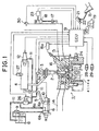
- Fig. 1 is a schematic illustration of the construction of a fuel injection control apparatus for an accumulator type diesel engine wherein the apparatus is installed in a vehicle.
- a diesel engine 1 has a plurality of cylinders (four cylinders #1-#4 in this comparative example).
- a combustion chamber of each cylinder #1-#4 is provided with an injector 2 that constitutes a fuel injection device.
- the fuel injection from each injector 2 into the corresponding one of the cylinders #1-#4 of the diesel engine 1 is controlled by turning on and off an injection control electromagnetic valve 3.
- the injectors 2 are connected to a common rail 4, that is, an accumulator pipe provided commonly for all the cylinders #1-#4. Basically, fuel from the common rail 4 is injected into the cylinders #1-#4 by the injectors 2 when the respective electromagnetic valves 3 are open.
- the common rail 4 needs to successively accumulate relatively high fuel pressures corresponding to the fuel injection pressure, particularly at the time of start of the engine.
- the common rail 4 is connected to an ejection port 6a of a supply pump 6 by a supply pipe 5.
- a check valve 7 is disposed in part way of the supply pipe 5. The check valve 7 allows fuel to be supplied from the supply pump 6 to the common rail 4 and restricts reverse flow of fuel from the common rail 4 to the supply pump 6.
- the supply pump 6 is connected to a fuel tank 8, via an intake port 6b.
- a filter 9 is provided in part way of the pipe between the intake port 6b and the fuel tank 8.
- the supply pump 6 draws fuel from the fuel tank 8 through the filter 9.
- the supply pump 6 reciprocates a plunger by using a cam (not shown) that is synchronized with revolution of the diesel engine 1, in order to increase the fuel pressure to a predetermined required pressure. Then, the supply pump 6 supplies high-pressure fuel to the common rail 4.
- the pressure control valve 10 controls the pressure of fuel ejected (therefore, the amount of fuel ejected) from the ejection port 6a toward the common rail 4.
- the pressure control valve 10 closes its valve body to allow fuel to be supplied from the ejection port 6a toward the common rail 4.
- the pressure control valve 10 opens its valve body to return surplus fuel that is not ejected from the ejection port 6a, from the supply pump 6 to the fuel tank 8, via a return port 6c of the supply pump 6 and a return pipe 11.
- the common rail 4 has a relief valve 12. If a predetermined condition is met, the relief valve 12 is opened, so that high-pressure fuel in the common rail 4 is returned to the fuel tank 8 through the return pipe 11 to reduce the pressure in the common rail 4.
- the injectors 2 inject fuel into the cylinders #1-#4 when the electromagnetic valves 3 are driven. Furthermore, each injector 2 has a mechanism for releasing fuel therefrom so as to reduce the fuel pressure in the common rail 4 during an initial period (hereinafter, referred to as "ineffective injection time") after the driving of the corresponding electromagnetic valve 3 is started. This mechanism will be described below.
- a casing 61 of each injector 2 is provided with a supply port 62 that is connected to the common rail 4 by a supply pipe 63. Therefore, fuel from the common rail 4 is introduced through the supply port 62 into a lower fuel reservoir chamber 64 formed in a lower portion of the casing 61. Nozzle pores 65 that can communicate with the lower fuel reservoir chamber 64 are formed in a lowest portion of the casing 61.
- the supply port 62 is also connected to an upper fuel reservoir chamber 67, via an orifice 66.
- a nozzle needle 68 is slidably disposed extending in the lower fuel reservoir chamber 64 and the upper fuel reservoir chamber 67.
- the nozzle needle 68 has a distal end portion 69, a large-diameter portion 70, a small-diameter portion 71 and a piston portion 72 that are formed in that order from the bottom.
- the nozzle needle 68 is disposed so that the large-diameter portion 70 is movable up and down within an upper portion of the lower fuel reservoir chamber 64 and so that the piston portion 72 is movable up and down within a lower portion of the upper fuel reservoir chamber 67.
- a nozzle needle spring 73 is disposed surrounding the outer peripheral surface of the small-diameter portion 71. The spring 73 normally urges the nozzle needle 68 downwardly in Fig. 2A. Therefore, the distal end portion 69 of the nozzle needle 68 is normally in contact with a seat portion 74 of the casing 61 that is formed near the nozzle pores 65.
- the upper fuel reservoir chamber 67 is connected to an electromagnetic valve housing chamber 76, via an orifice 75.
- the electromagnetic valve 3 is formed by a valve body 77, a solenoid 78, a valve body spring 79 and the like, which are disposed in the electromagnetic valve housing chamber 76. More specifically, the valve body 77 is disposed in a lower portion of the electromagnetic valve housing chamber 76.
- the valve body spring 79 is disposed in contact with the valve body 77 and a ceiling of the electromagnetic valve housing chamber 76. The spring 79 normally urges the valve body 77 downward so as to close the orifice 75, thereby shutting down the communication between the upper fuel reservoir chamber 67 and the electromagnetic valve housing chamber 76.
- the solenoid 78 when excited, draws the valve body 77 upward in Fig. 2A, against the urging force of the valve body spring 79.
- the valve body 77 has a flanged upper portion in which through-holes 77a are formed.
- the casing 61 has a return port 80 for releasing fuel from the electromagnetic valve housing chamber 76. Under a predetermined condition, surplus fuel is returned from the return port 80 to the fuel tank 8 through the return pipe 11.
- a space in which the nozzle needle spring 73 is disposed and the electromagnetic valve housing chamber 76 are connected in communication with each other by a communication channel 81.
- each injector 2 will be described.
- the solenoid 78 When the solenoid 78 is not excited, the valve body 77 is urged downward by the valve body spring 79, thereby shutting down the communication between the upper fuel reservoir chamber 67 and the electromagnetic valve housing chamber 76, as shown in Fig. 2A.
- fuel from the supply port 62 is supplied equally to the lower fuel reservoir chamber 64 and the upper fuel reservoir chamber 67 so that pressure balance is maintained. Consequently, the nozzle needle 68 is urged downward by the nozzle needle spring 73 so that the distal end portion 69 of the nozzle needle 68 is held in contact with the seat portion 74 formed near the nozzle pores 65. In this case, therefore, fuel is not injected from the nozzle pores 65, and fuel does not quickly flow out of the upper fuel reservoir chamber 67 into the return port 80.
- the solenoid 78 draws the valve body spring 79 upwardly against the urging force of the valve body spring 79, so that the electromagnetic valve housing chamber 76 comes into communication with the upper fuel reservoir chamber 67.
- the injector 2 undergoes a transient process or state as indicated in Fig. 2B. That is, since the valve body 77 moves upward, fuel flows from the upper fuel reservoir chamber 67 into the return pipe 11 through the through-holes 77a and the return port 80.
- the difference between the fuel pressure in the lower fuel reservoir chamber 64 and the fuel pressure in the upper fuel reservoir chamber 67 remains smaller than the urging force of the nozzle needle spring 73.
- the nozzle needle 68 remains still, so that the distal end portion 69 remains in contact with the seat portion 74. Consequently, in this condition, fuel is not injected from the nozzle pores 65, but fuel quickly flows out of the upper fuel reservoir chamber 67 into the return pipe 11 through the return port 80. This period is the ineffective injection time.
- the excitation of the solenoid 78 is discontinued, so that the injector 2 resumes the state as indicated in Fig. 2A, thereby completing fuel injection. If the excitation time of the solenoid 78 is less than the ineffective injection time, the transition from the state as indicated in Fig. 2B to the state as indicated in Fig. 2C does not occur. In such a case, fuel injection does not occur, but mere quick outflow of fuel from the upper fuel reservoir chamber 67 into the return pipe 11 through the return port 80 occurs.
- an intake air channel 13 and an exhaust gas channel 14 are connected to the combustion chambers of the diesel engine 1.
- the intake air channel 13 is provided with a throttle valve (not shown). By operating the throttle valve, the flow of intake air to be introduced into each combustion chamber is adjusted.
- a glow plug 16 is provided for each combustion chamber of the diesel engine 1.
- Each glow plug 16 is an engine starting assistant device that is heated to glow by supplying current through a glow relay 16a immediately before the diesel engine 1 is started. By contacting a portion of a spray of injected fuel, the heated glow plug 16 in each chamber promotes ignition and combustion of fuel.
- the diesel engine 1 is equipped with various sensors for detecting conditions of the diesel engine 1. These sensors form a state detection device.
- An accelerator sensor 21 is provided near an accelerator pedal 15, for detecting depression ACCP of the accelerator pedal 15.
- a complete closure switch 22 that outputs a complete closure signal when the depression of the accelerator pedal 15 is zero.
- An intake air pressure sensor 23 is connected to the intake air channel 13, with a f ilter 17 and a vacuum switching valve (VSV) 18 disposed therebetween.
- the intake air pressure 23 detects pressure of intake air (intake air pressure PM) within the intake air channel 13.
- a coolant temperature sensor 24 is provided in a cylinder block of the diesel engine 1, for detecting temperature of cooling water (coolant temperature THW) therein.
- the diesel engine 1 also has a starter 19 for starting the engine 1.
- the starter 19 has a starter switch 25 that detects an operating state thereof.
- the starter switch 25 outputs an starter signal STA at an on-status when the ignition switch (not shown) is operated from an OFF position to a START position so that the starter 19 operates (that is, a cranking state is assumed) to start the diesel engine 1.
- the starter switch 25 When the starting of the diesel engine 1 is completed (a complete combustion state is assumed) or it has failed and the ignition switch is returned from the START position to an ON position, the starter switch 25 outputs the starter signal STA at an off-status.
- the starting state of the engine is defined as the period from the time when the starter signal STA becomes on-status to the time before when the engine is under the complete combustion state.
- the complete combustion state is defined as the state that an ordinary combustion can be occurred in all cylinders of the engine.
- a fuel temperature sensor 26 is provided in the return pipe 11, for detecting a fuel temperature THF.
- a fuel pressure sensor 27 is provided in the common rail 4, as a fuel pressure detection device for detecting pressure of fuel (fuel pressure PC) in the common rail 4.
- an engine speed sensor 28 for detecting engine revolution speed is provided near a pulser that is provided at a crank shaft (not shown) of the diesel engine 1. Revolution of the crank shaft is transmitted to a cam shaft (not shown) for opening and closing an intake air valve 31 and an exhaust gas valve 32, by a timing belt and the like. The transmission mechanism is designed so that the cam shaft revolves at a revolution rate of 1/2 of that of the crank shaft.
- a G-sensor 29 is provided near a pulser that is provided at the cam shaft.
- an engine revolution speed NE, a crank angle CA and a top dead center (TDC) of each cylinder #1-#4 are calculated on the basis of pulse signals from the sensors 28, 29.
- intake air temperature THA is provided near an air cleaner (not shown) provided at an inlet opening of the intake air channel 13.
- An electronic control unit (ECU) 51 for performing various controls on the diesel engine 1 is provided.
- the ECU 51 functions as a fuel injection device, a target fuel pressure calculating device, a pressure supply stop device, and the like.
- the ECU 51 has a central processing unit (CPU) 52, a read-only memory (ROM) 53 in which predetermined programs, maps and the like are pre-stored, a random access memory (RAM) 54 for temporarily storing the results of calculations and operations executed by the CPU 52, a backup RAM 55 for storing pre-stored data and the like, a timer counter 56, and the like.
- the ECU 51 further has an input interface 57, an output interface 58 and the like.
- the aforementioned components 52-56 are connected to the input interface 57 and the output interface 58 by busses 59.
- Each of the accelerator sensor 21, the intake air pressure 23, the coolant temperature sensor 24, the fuel temperature sensor 26, the fuel pressure sensor 27, the intake air temperature sensor 30 and the like is connected to the input interface 57, via a buffer, a multiplexer and an A/D converter (which are not shown).
- Each of the engine speed sensor 28 and the G-sensor 29 is connected to the input interface 57, via a waveform shaping circuit.
- the complete closure switch 22 and the starter switch 25 are directly connected to the input interface 57.
- the CPU 52 reads in the signals from the sensors and the like 21-30, via the input interface 57.
- Each of the electromagnetic valve.3, the pressure control valve 10, the relief valve 12 and the vacuum switching valve (VSV) 18 is connected to the output interface 58, via a driving circuit (not shown).
- the CPU 52 suitably controls the electromagnetic valve 3, the pressure control valve 10, the relief valve 12, the vacuum switching valve 18 and the like, based on the input values read via the input interface 57.
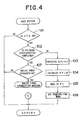
- FIG. 4 is a flowchart illustrating a main routine executed by the ECU 51. This routine is started when a driving person switches the ignition switch from an OFF position to an ON position. That is, the main routine is started before the cylinder discrimination is performed.
- the ECU 51 determines in step 101 whether the present starter signal STA is at an on-status. If the starter signal STA is at an off-status, the ECU 51 temporarily ends the routine. Conversely, if the starter signal STA is at the on-status, the ECU 51 determines in step 102 whether the discrimination of the cylinders has been completed. More specifically, it is determined in step 102 whether the calculation of an engine resolution speed NE, a crank angle CA and the top dead center of each cylinder #1-#4 has been completed so that fuel injection is possible. If the cylinder discrimination has not been completed, the ECU 51 proceeds to step 103.
- step 103 the ECU 51 calculates a provisional target injection amount QFINC (not actually injected). Subsequently in step 104, the ECU 51 calculates a target fuel pressure PFIN.
- step 105 the ECU 51 reads in a present fuel pressure PC based on the signal from the fuel pressure sensor 27.
- the ECU 51 sets the control mode to a starting-time mode. That is, the control of the pressure control valve 10 is performed without performing fuel injection or the like, basically in order to increase the fuel pressure PC in the common rail 4.
- steps 103 through 106 the calculation of the target fuel pressure PFIN and the reading of the actual fuel pressure PC are performed even though the cylinder discrimination has not been completed.
- the calculated target fuel pressure PFIN and the read actual fuel pressure PC are temporarily stored into the RAM 54.
- step 107 the ECU 51 determines whether there is an engine speed pulse interrupt signal from the engine speed sensor 28. If there is not the engine speed pulse interrupt signal, the ECU 51 temporarily ends this routine. If there is the engine speed pulse interrupt signal, the ECU 51 executes an engine speed interruption routine.
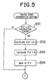
- Fig. 5 is a flowchart illustrating the engine speed interruption routine executed by the ECU 51. This routine is executed every time when the engine speed pulse interrupt signal as described above is present.
- the ECU 51 determines in step 201 whether it is presently a calculation timing for the target injection amount QFINC. If it is not the calculation timing for the target injection amount QFINC, the ECU 51 temporarily ends this routine. If it is the calculation timing for the target injection amount QFINC, the ECU 51 calculates the target injection amount QFINC based on the various signals indicating the present state of the diesel engine 1 in step 202. Subsequently, the ECU 51 calculates the target fuel pressure PFIN in step 203, and reads in the present fuel pressure PC based on the signal from the fuel pressure sensor 27 in step 204. The calculated target fuel pressure PFIN and the read fuel pressure PC are temporarily stored into the RAM 54. Then, the ECU 51 temporarily ends this routine.
- the embodiment calculates the target injection amount QFINC and reads in the actual fuel pressure PC in the main routine. After the cylinder discrimination has been completed, the embodiment calculates the target fuel pressure PFIN and reads in the actual fuel pressure PC in the engine speed interruption routine.
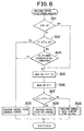
- Fig. 6 is a flowchart illustrating a pressure control valve control routine executed by the ECU 51. This routine is started when the ignition switch is switched from the OFF position to the ON position.
- step 301 determines in step 301 whether the present engine revolution speed NE is "0". If the engine revolution speed NE is "0”, the operation jumps to step 305, which is described later. If the engine revolution speed NE is not "0", the operation proceeds to step 302.
- step 302 the ECU 51 determines whether the present starter signal STA is at the on-status. If the starter signal STA is at the off-status, it is indicated that the diesel engine 1 has been started. The operation therefore proceeds to step 303.
- step 303 the ECU 51 executes feedback-control of the pressure control valve 10. After that, the pressure control valve control routine is temporarily ended. More specifically, in step 303, the pressure control valve 10 is feedback-controlled so that the actual fuel pressure PC becomes equal to the target fuel pressure PFIN.
- step 302 If it is determined in step 302 that the starter signal STA is at the on-status, the operation proceeds to step 304.
- step 304 the ECU 51 determines whether the cylinder discrimination has been completed. If the cylinder discrimination has been completed, the operation proceeds to step 303, where the feedback control of the pressure control valve 10 is performed as described above. After that, the ECU 51 temporarily ends this routine.
- step 305 the ECU 51 reads from the RAM 54 the target fuel pressure PFIN calculated in the main routine. Subsequently in step 306, the ECU 51 reads from the RAM 54 the actual fuel pressure PC detected in the main routine.
- step 307 the ECU 51 determines whether the actual fuel pressure PC is greater than the target fuel pressure PFIN. If the actual fuel pressure PC is not greater than the target fuel pressure PFIN, the ECU 51 executes in step 308 the starting-time control of the pressure control valve 10 (generally termed "full pressure supply control") in order to increase the fuel pressure PC in the common rail 4. Therefore, a maximum fuel pressure is supplied from the supply pump 6 to the common rail 4, so that the fuel pressure PC in the common rail 4 is quickly increased.
- full pressure supply control the starting-time control of the pressure control valve 10
- step 309 the control of switching the pressure control valve 10 off. Therefore, the pressure control valve 10 is caused to open its valve body so as to return surplus fuel that is not ejected from the ejection port 6a, to the fuel tank 8 through the return port 7c and the return pipe 11. Consequently, further increase of the fuel pressure PC in the common rail 4 is curbed, and the fuel pressure PC is gradually decreased.
- the comparative example Before the cylinder discrimination at the time of start of the diesel engine 1, the comparative example performs the starting-time control of the pressure control valve 10, that is, the control of supplying full fuel pressure to the common rail 4.
- the pressure control valve 10 the control of supplying full fuel pressure to the common rail 4.
- This comparative example calculates the target fuel pressure PFIN and detects the actual fuel pressure PC even before the cylinder discrimination. If the actual fuel pressure PC is greater than the target fuel pressure PFIN, the pressure control valve 10 is switched off even before the cylinder discrimination. This switching-off control curbs further increase of the fuel pressure PC in the common rail 4 and gradually reduces the fuel pressure PC. Therefore, this prevents an event that after the cylinder discrimination is completed, the fuel pressure PC in the common rail 4 is excessively high. Consequently, this substantially prevents occurrence of loud combustion noises due to excessive degree of the spraying of fuel after the diesel engine 1 is started.
- the engine speed interruption routine is not performed before the cylinder discrimination is completed.
- this comparative example calculates the target fuel pressure PFIN and detects the actual fuel pressure PC in the main routine. Therefore, the target fuel pressure PFIN and the fuel pressure PC can be reliably acquired and monitored continually and substantially immediately after the ignition switch has been operated to the ON position. Therefore, the prevention of loud combustion noises can be ensured.
- the present comparative example has a feature that the fuel pressure PC is controlled by the on-off control of the relief valve 12 provided in the common rail 4.
- Fig. 7 is a flowchart illustrating a relief valve control routine executed by the ECU 51. This routine is started when the ignition switch is operated from the OFF position to the ON position.
- step 401 determines in step 401 whether the present engine revolution speed NE is "0". If the present engine revolution speed NE is "0”, the operation jumps to step 404, which is described later. If the engine revolution speed NE is not "0", the operation proceeds to step 402.
- step 402 the ECU 51 determines whether the present starter signal STA is at the on-status. If the starter signal STA is at the off-status, it is indicated that the diesel engine 1 has been started. The operation therefore proceeds to step 409. In step 409, no control is performed on the relief valve 12, but feedback control is performed on the pressure control valve 10. Subsequently, this routine is temporarily ended.
- step 402 If it is determined in step 402 that the starter signal STA is at the on-status, the operation proceeds to step 403.
- step 403 the ECU 51 determines whether the cylinder discrimination has been completed. If the cylinder discrimination has been completed, the operation proceeds to step 409, where the feedback control of the pressure control valve 10 is performed as described above. After that, the ECU 51 temporarily ends this routine.
- step 404 the ECU 51 reads from the RAM 54 the target fuel pressure PFIN calculated in the main routine. Subsequently in step 405, the ECU 51 reads from the RAM 54 the actual fuel pressure PC detected in the main routine.
- step 406 the ECU 51 determines whether the actual fuel pressure PC is greater than the target fuel pressure PFIN. If the actual fuel pressure PC is not greater than the target fuel pressure PFIN, the operation proceeds to step 407. In step 407, the ECU 51 keeps the relief valve 12 in an off-state, and executes the starting-time control of the pressure control valve 10, in order to prevent escape of the fuel pressure PC from the common rail 4. Therefore, escape of the fuel pressure PC from the common rail 4 is prevented, and the fuel pressure PC in the common rail 4 is increased by execution of the starting-time control of the pressure control valve 10.
- step 408 the control of switching on the relief valve 12. Therefore, the relief valve 12 is opened so as to return high-pressure fuel from the common rail 4 to the fuel tank 8 through the relief valve 12 and the return pipe 11. Consequently, the fuel pressure PC quickly decreases.
- the comparative example rapidly releases high-pressure fuel from the common rail 4 by the switching-on control of the relief valve 12. This release control more quickly reduces the fuel pressure PC. Therefore, the comparative example quickly reduces the fuel pressure PC even in a case where the cylinder discrimination is completed immediately after the actual fuel pressure PC exceeds the target fuel pressure PFIN. Consequently, the prevention of occurrence of loud combustion noises can be further ensured.
- the present comparative example has a feature that the fuel pressure PC is controlled by controlling the electromagnetic valve 3 provided in each injector 2.
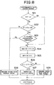
- Fig. 8 is a flowchart illustrating an electromagnetic valve control routine executed by the ECU 51. This routine is started when the ignition switch is operated from the OFF position to the ON position, as in the routine in the second embodiment.
- the ECU 51 executes a process of steps 501 through 505 and step 508 substantially the same as the process of steps 401 through 405 and step 409 in the second embodiment (step 409 corresponding to step 508).
- step 506 the ECU 51 determines whether the actual fuel pressure PC is greater than the target fuel pressure PFIN. If the actual fuel pressure PC is not greater than the target fuel pressure PFIN, which means that it is in a stage before fuel injection, then the operation proceeds to step 509. In step 509, the ECU 51 does not execute any particular control of the electromagnetic valve 3, but executes the starting-time control of the pressure control valve 10. Subsequently, this routine is temporarily ended.
- step 507 executes the ineffective injection control (see Fig. 2B).
- the ineffective injection control the solenoid 78 of the electromagnetic valve 3 is excited for a time that is less than the ineffective injection time. This control does not allow fuel to be injected from the nozzle pores 65, but allows fuel to quickly flow out of the upper fuel reservoir chamber 67 into the return port 80. Therefore, the fuel pressure PC in the common rail 4 decreases.
- Figs. 9 and 10 show a flowchart illustrating a restart determining routine executed by the ECU 51 to determine whether the present engine starting operation is the restart or the try-again restart.
- This routine is started when the ignition switch is operated from the OFF position to the ON position.
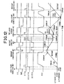
- Fig. 12 shows a timing chart illustrating example behaviors over time of the state of the ignition switch (IG), the conduction state of the main relay (MR) (that is, the power source for starting the ECU 51), the starter signal STA, the water temperature THW and the like.
- IG state of the ignition switch
- MR conduction state of the main relay
- STA the starter signal
- water temperature THW water temperature
- step 601 determines in step 601 in Fig. 9 whether the present engine revolution speed NE is "0". If the engine revolution speed NE is not "0", the operation proceeds to step 612.
- step 612 it is determined whether the starter signal STA is presently at the on-status. If the starter signal STA is at the on-status, the ECU 51 sets a try-again restart determination flag XGSTO to "1" in step 613. Subsequently in step 614, the present water temperature THW is set and stored as a starting-time water temperature THWON.
- step 601 determines whether the engine revolution speed NE is "0"
- step 602 determines whether the engine 1 is presently in an engine-stalled state.
- the conditions for determining that it is in the engine-stalled state are, for example, that the main relay MR is on, and that the engine revolution speed NE is "0", and the like. If it is determined in step 602 that the engine 1 is presently in the engine-stalled state, the operation proceeds to step 611, where a restart determination flag XSTO is set to "1".
- step 603 determines in step 603 whether the starter signal STA is at the off-status. If the starter signal STA is at the on-status, the operation proceeds to step 613, where the ECU 51 sets the try-again restart determination flag XGSTO to "1". Subsequently in step 612, the ECU 51 sets and stores the present water temperature THW as the starting-time water temperature THWON. Thus, if at least the starter signal STA is switched to the on-status, the try-again restart determination flag XGSTO is set to "1".
- step 603 If it is determined in step 603 that the starter signal STA is at the off-status, the ECU 51 determines in step 604 whether the try-again restart determination flag XGSTO is presently "1". If the try-again restart determination flag XGSTO is not presently "1", the operation jumps to step 606. Conversely, if the try-again restart determination flag XGSTO is presently "1", the operation proceeds to step 605.
- step 605 the ECU 51 determines whether the try-again restart is actually being performed. More specifically, it is determined whether the value obtained by subtracting the presently stored starting-time water temperature THWON from a IG-off-time learned water temperature value GTHWIOF learned at the time of the switching-off of the ignition switch is greater than a pre-set value ⁇ . If the determination in step 605 is negative, it means that there is no substantial water temperature decrease from the IG-off-time learned water temperature value GTHWIOF to the water temperature at the time of the switching-on of the starter 19 (starting-time water temperature THWON). Therefore, it is determined that the present engine starting operation is the try-again start. In this case, the ECU 51 proceeds to step 617 in Fig.
- step 605 determines whether there is a water temperature decrease from the IG-off-time learned water temperature value GTHWIOF to the water temperature at the time of the switching-on of the starter 19 (starting-time water temperature THWON). Therefore, it is determined that the present engine starting operation is not the try-again start. In this case, the ECU 51 proceeds to step 606.
- step 606 it is determined whether the present engine starting operation is the restart. More specifically, in step 606, the ECU 51 determines whether the fuel temperature THF detected by the fuel temperature sensor 26 is substantially equal to the intake air temperature THA detected by the intake air temperature sensor 30. If the fuel temperature THF and the intake air temperature THA are considerably different, the operation jumps to step 609.
- the ECU 51 determines in step 607 whether the present fuel temperature THF is higher than a lowest learned water temperature value GTHWMN.
- the lowest learned water temperature value GTHWMN is the lowest value of the water temperature THW that has been obtained.
- the lowest learned water temperature value GTHWMN is learned and updated every time a new lowest value is obtained. If the present fuel temperature THF is not higher than the lowest learned water temperature value GTHWMN, the operation jumps to step 609.
- step 607 if it is determined in step 607 that the present fuel temperature THF is higher than the lowest learned water temperature value GTHWMN, the ECU 51 sets the present fuel temperature THF as the lowest learned water temperature value GTHWMN. That is, for example, if the lowest learned water temperature value GTHWMN obtained the previous day is "0°C" and the present fuel temperature THF is "5°C", the present fuel temperature THF is set as a new lowest learned water temperature value GTHWMN.
- step 609 the ECU 51 determines in step 609 whether the presently set lowest learned water temperature value GTHWMN is lower than the present water temperature THW. If the presently set lowest learned water temperature value GTHWMN is not lower than the present water temperature THW, the ECU 51 sets the present water temperature THW as the lowest learned water temperature value GTHWMN in step 615. The present water temperature THW being lower than the presently set lowest learned water temperature value GTHWMN indicates that the engine is presently in a cold start state. Subsequently in step 616, the ECU 51 sets the restart determination flag XSTO to "0". The operation then proceeds to step 617.
- step 609 the operation proceeds to step 610.
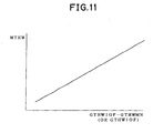
- step 610 the ECU 51 determines whether the value obtained by subtracting the presently set lowest learned water temperature value GTHWMN from the present water temperature THW is greater than a reference value MTHW.
- the reference value MTHW is determined corresponding to the value obtained by subtracting the presently set lowest learned water temperature value GTHWMN from the IG-off-time learned water temperature value GTHWIOF, by referring to a map as indicated in Fig. 11. As can be seen from Fig.
- the reference value MTHW increases with increases in the value obtained by subtracting the presently set lowest learned water temperature value GTHWMN from the IG-off-time learned water temperature value GTHWIOF.
- This map is adopted on consideration that the water temperature decreasing manner differs between a case where the water temperature is relatively low at the time of turning-off of the ignition switch, and a case where the water temperature is relatively high at the time of turning-off of the ignition switch. If the value obtained by subtracting the presently set lowest learned water temperature value GTHWMN from the present water temperature THW is not greater than the reference value MTHW, it is determined that the engine is in the cold start state. Therefore, the ECU 51 sets the restart determination flag XSTO to "0" in step 616, and then proceeds to step 617.
- step 611 the ECU 51 sets the restart determination flag XSTO to "1". The operation subsequently proceeds to step 617.
- step 601 through 616 it is determined whether the engine 1 is presently in the try-again restart state and, if the determination is negative, it is then determined whether the engine 1 is presently in the cold start state or the restart state.
- step 617 the ECU 51 determines in step 617 in Fig. 10 whether the ignition switch is presently in an on-state. If the ignition switch is presently in the on-state, the ECU 51 temporarily ends this routine. Conversely, if the ignition switch is presently in an off-state, the operation proceeds to step 618.
- step 618 the ECU 51 determines whether the main relay MR is presently in the on-state. If the main relay MR is presently in the off-state, it is determined that a considerably long time has elapsed following the previous stop of the diesel engine 1. Therefore, the ECU 51 temporarily ends this routine. If the main relay MR is in the on-state, it means that the elapsed time following the switching of the ignition switch from the on-state to the off-state is not considerably long. Therefore, the ECU 51 proceeds to step 618, in order to execute an operation to be performed after the ignition switch has been turned off.
- step 619 the ECU 51 sets and stores the present water temperature THW as the IG-off-time learned water temperature value GTHWIOF.
- step 620 the ECU 51 determines whether the try-again restart determination flag XGSTO is presently "1". If the try-again restart determination flag XGSTO is "0", the ECU 51 temporarily ends this routine without executing any further processing. Conversely, if the try-again restart determination flag XGSTO is "1", the ECU 51 proceeds to step 621, in order to determine whether it is appropriate to hold the flag at "1".
- step 621 the ECU 51 determines whether the value obtained by subtracting the presently set IG-off-time learned water temperature value GTHWIOF from the starting-time cooling water temperature THWON is less than a pre-set value ⁇ . If the value obtained by subtracting the presently set IG-off-time learned water temperature value GTHWIOF from the starting-time water temperature THWON is less than the pre-set value ⁇ , it is determined that it is appropriate to hold the try-again restart determination flag XGSTO at "1". Therefore, the ECU 51 temporarily ends this routine without executing any further processing.
- step 622 the ECU 51 sets the try-again restart determination flag XGSTO to "0". The ECU 51 then temporarily ends this routine. Thus, in steps 617 through 622, the ECU 51 performs the operation that is to be performed after the ignition switch has been turned off.
- This embodiment performs the control of the fuel pressure PC in the common rail 4 based on the try-again restart determination flag XGSTO and the restart determination flag XSTO set as described above. The content of this control will be described below.
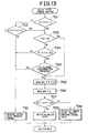
- Fig. 13 is a flowchart illustrating a relief valve control routine executed by the ECU 51 according to the first embodiment. This routine is started when the ignition switch is operated from the OFF position to the ON position.
- step 701 determines in step 701 whether the restart determination flag XSTO is presently "1". If the restart determination flag XSTO is "1", the ECU 51 proceeds to step 703, in order to execute the control of the fuel pressure PC in the common rail 4 according to this embodiment. Conversely, if the restart determination flag XSTO is "0", the operation proceeds to step 702.
- step 702 the ECU 51 determines whether the try-again restart determination flag XGSTO is presently "1". If the try-again restart determination flag XGSTO is "1", the ECU 51 proceeds to step 703, in order to execute the control of the fuel pressure PC in the common rail 4 according to this embodiment. Conversely, if try-again restart determination flag XGSTO is "0", the ECU 51 executes the feedback control of the pressure control valve 10 in step 710, and then temporarily ends this routine.
- step 703 determines in step 703 whether the present engine revolution speed NE is "0". If the engine revolution speed NE is "0", the operation jumps to step 705, which is described later. Conversely, if the engine revolution speed NE is not "0", the operation proceeds to step 704.
- step 704 the ECU 51 determines whether the present starter signal STA is at the on-status. If the starter signal STA is at the off-status, it is determined that the diesel engine 1 has been started. Therefore, the ECU 51 temporarily ends this routine without performing any processing regarding the relief valve 12.
- step 704 determines whether the starter signal STA is at the on-status. If it is determined in step 704 that the starter signal STA is at the on-status, the operation proceeds to step 700.
- step 700 the ECU 51 determines whether the cylinder discrimination has been completed. If the cylinder discrimination has been completed, the ECU 51 executes the feedback control of the pressure control valve 10 in step 710, and then temporarily ends this routine. If it is determined in step 700 that the cylinder discrimination has not been completed, the operation proceeds to step 705.
- step 705 the ECU 51 reads out the target fuel pressure PFIN stored in the main routine described above in conjunction with the comparative example. Subsequently in step 706, the ECU 51 reads out the actual fuel pressure PC stored in the main routine.
- step 707 the ECU 51 determines whether the actual fuel pressure PC is greater than the target fuel pressure PFIN. If the actual fuel pressure PC is not greater than the target fuel pressure PFIN, the ECU 51 keeps the relief valve 12 in the off-state and executes the starting-time control of the pressure control valve 10 in step 708, in order to prevent escape of the fuel pressure PC from the common rail 4. Therefore, escape of the fuel pressure PC from the common rail 4 is prevented, and the fuel pressure PC in the common rail 4 is increased by execution of the starting-time control of the pressure control valve 10.
- step 709 the control of switching on the relief valve 12. Therefore, the relief valve 12 is opened so as to return high-pressure fuel from the common rail 4 to the fuel tank 8 through the relief valve 12 and the return pipe 11. Consequently, the fuel pressure PC quickly decreases.
- this embodiment rapidly releases high-pressure fuel from the common rail 4 by the switching-on control of the relief valve 12.
- This release control more quickly reduces the fuel pressure PC. Therefore, the fourth embodiment quickly reduces the fuel pressure PC even in a case where the cylinder discrimination is completed immediately after the actual fuel pressure PC exceeds the target fuel pressure PFIN. Consequently, the prevention of occurrence of loud combustion noises can be further ensured.
- the first embodiment compares the actual fuel pressure PC and the target fuel pressure PFIN if it is determined that the engine 1 is in the restart state or the try-again restart state.
- the fuel pressure PC in the common rail 4 is relatively high since it has not been long after the stop of the previous operation of the diesel engine 1. since the fuel supply control using the supply pump 6 is performed in such a relatively high fuel pressure condition, the actual fuel pressure PC is likely to exceed the target fuel pressure PFIN.
- the driving person operates the ignition switch to operate the starter 19 again.
- the pressure supply control using the supply pump 6 is performed to .increase the fuel pressure PC in the common rail 4, so that fuel pressure PC will more likely exceed the target fuel pressure PFIN.
- the first embodiment performs the control described above under a condition that the fuel pressure PC is likely to become high, so that excessively high fuel pressure PC in the common rail 4 can be more effectively prevented.
- the first embodiment takes into consideration the intake air temperature THA and the fuel temperature THF as well as the cooling water temperature THW (steps 606-610, 615). Therefore, even if one of the sensors 24, 26, 30 fails, this embodiment can reliably determine whether the engine is in the restart state.
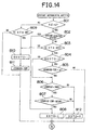
- a second embodiment of the invention will be described with reference to Fig. 14 through 16.
- the construction, components and the like of this embodiment are substantially the same as those before. Therefore, like components, portions and so on are represented by like reference characters in the drawings, and will not be described again.
- the following description of the second embodiment is mainly focused on the features different from those of the foregoing.
- the first embodiment determines whether the preset engine starting operation is the restart or whether the present starting operation is the try-again restart. If either determining process makes affirmative determination, the first embodiment then proceeds to determine whether the actual fuel pressure PC is greater than the target fuel pressure PFIN.
- the second embodiment is substantially the same as the first embodiment in that the aforementioned determining processes are performed. However, the second embodiment is distinguished from the first embodiment in the methods of determining whether the present engine starting operation is the restart or the try-again restart.
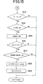
- Figs. 14 and 15 show a flowchart illustrating a restart determining routine executed by the ECU 51 to determine whether the diesel engine 1 is in the restart state or the try-again restart state.
- This routine is started when the ignition switch is operated from the OFF position to the ON position.
- Fig. 16 shows a timing chart illustrating example behaviors over time of the state of the ignition switch (IG), the conduction state of the main relay (MR) (that is, the power source for starting the ECU 51), the starter signal STA, the water temperature THW and the like.
- IG state of the ignition switch
- MR conduction state of the main relay
- STA the starter signal
- water temperature THW water temperature
- step 801 determines in step 801 in Fig. 14 whether the present engine revolution speed NE is "0". If the engine revolution speed NE is not "0", the operation proceeds to step 809. In step 809, it is determined whether the starter signal STA is presently at the on-status. If the starter signal STA is at the on-status, the ECU 51 sets the try-again restart determination flag XGSTO to "1" in step 810. Subsequently in step 811, the present water temperature THW is set and stored as a starter-on-time learned water temperature value GTHWSON.
- step 801 determines whether the engine revolution speed NE is "0"
- step 802 determines whether the engine 1 is presently in the engine-stalled state. If the engine 1 is presently in the stalled state, the operation proceeds to step 808, where the restart determination flag XSTO is set to "1".
- step 803 determines in step 803 whether the starter signal STA is at the off-status. If the starter signal STA is at the on-status, the operation proceeds to step 810, where the ECU 51 sets the try-again restart determination flag XGSTO to "1". Subsequently in step 811, the ECU 51 sets and stores the present water temperature THW as the starter-on-time learned water temperature value GTHWSON. Thus, if at least the starter signal STA is switched to the on-status, the try-again restart determination flag XGSTO is set to "1".
- step 803 If it is determined in step 803 that the starter signal STA is at the off-status, the ECU 51 determines in step 804 whether the try-again restart determination flag XGSTO is presently "1". If the try-again restart determination flag XGSTO is not presently "1", the operation jumps to step 806. Conversely, if the try-again restart determination flag XGSTO is presently "1", the operation proceeds to step 805.
- step 805 the ECU 51 determines whether the try-again restart is actually being performed. More specifically, it is determined whether the value obtained by subtracting the present water temperature THW from the starter-on-time learned water temperature value GTHWSON is greater than a pre-set value ⁇ (which may be different from the value ⁇ in the first embodiment). If the determination in step 805 is negative, it means that there is no substantial water temperature decrease from the starter-on-time learned water temperature value GTHWSON to the present water temperature THW. Therefore, it is determined that the present engine starting operation is the try-again start. In this case, the ECU 51 proceeds to step 813 in Fig. 15. Conversely, if the determination in step 805 is affirmative, it is determined that the present engine starting operation is not the try-again start. In this case, the ECU 51 proceeds to step 806.
- step 806 it is determined whether the present engine starting operation is the restart. More specifically, in step 806, the ECU 51 determines whether the IG-off-time learned water temperature value GTHWIOF is lower than the present water temperature THW. If the IG-off-time learned water temperature value GTHWIOF is not lower than the present water temperature THW, it is determined that the engine 1 is in the cold start condition. Therefore, the ECU 51 sets the restart determination flag XSTO to "0" in step 812, and then proceeds to step 813.
- step 806 determines whether the IG-off-time learned water temperature value GTHWIOF is lower than the present water temperature THW.
- step 807 the ECU 51 determines whether the value obtained by subtracting the present water temperature THW from the IG-off-time learned water temperature value GTHWIOF is less than a reference value MTHW.
- the reference value MTHW is determined corresponding to the IG-off-time learned water temperature value GTHWIOF, by referring to a map as indicated in Fig. 11 (see the parentheses in Fig. 11). As can be seen from Fig. 11, the reference value MTHW increases with increases in the IG-off-time learned water temperature value GTHWIOF.
- This map is adopted on consideration that the water temperature decreasing manner differs between a case where the water temperature is relatively low at the time of turning-off of the ignition switch and a case where the water temperature is relatively high at the time of turning-off of the ignition switch. If the value obtained by subtracting the present water temperature THW from the IG-off-time learned water temperature value GTHWIOF is not less than the reference value MTHW, it is determined that the engine 1 is in the cold start state. Therefore, the ECU 51 sets the restart determination flag XSTO to "0" in step 812, and then proceeds to step 813.
- step 808 the ECU 51 sets the restart determination flag XSTO to "1". The operation subsequently proceeds to step 813.
- steps 801 through 812 it is determined whether the engine 1 is presently in the try-again restart state and, if the determination is negative, it is then determined whether the engine 1 is presently in the cold start state or the restart state.
- step 813 the ECU 51 determines in step 813 in Fig. 15 whether the ignition switch is presently in the on-state. If the ignition switch is presently in the on-state, the ECU 51 temporarily ends this routine. Conversely, if the ignition switch is presently in the off-state, the operation proceeds to step 814.
- step 813 the ECU 51 determines whether the main relay MR is presently in the on-state. If the main relay MR is presently in the off-state, it is determined that a considerably long time has elapsed following the previous stop of the diesel engine 1. Therefore, the ECU 51 temporarily ends this routine. If the main relay MR is in the on-state, it means that the elapsed time following the switching of the ignition switch from the on-state to the off-state is not considerably long. Therefore, the ECU 51 proceeds to step 815, in order to execute an operation to be performed after the ignition switch has been turned off.
- step 815 the ECU 51 sets and stores the present water temperature THW as the IG-off-time water temperature value THWIOF.
- step 816 the ECU 51 determines whether the try-again restart determination flag XGSTO is presently "1". If the try-again restart determination flag XGSTO is "0", the ECU 51 temporarily ends this routine without executing any further processing. Conversely, if the try-again restart determination flag XGSTO is "1", the ECU 51 proceeds to step 817, in order to determine whether it is appropriate to hold the flag at "1".
- step 817 the ECU 51 determines whether the value obtained by subtracting the presently set IG-off-time water temperature value THWIOF from the starter-on-time learned water temperature value GTHWSON is less than a pre-set value ⁇ (which may be different from the value ⁇ in the first embodiment). If the value obtained by subtracting the IG-off-time water temperature value THWIOF from the starter-on-time learned water temperature value GTHWSON is less than the pre-set value ⁇ , it is determined that it is appropriate to hold the try-again restart determination flag XGSTO at "1". Therefore, the ECU 51 temporarily ends this routine without executing any further processing.
- step 818 the ECU 51 sets the present water temperature THW as the IG-off-time learned water temperature value GTHWIOF. Subsequently in step 819, the ECU 51 sets the try-again restart determination flag XGSTO to "0". Then, the ECU 51 temporarily ends this routine. Thus, in steps 813 through 819, the ECU 51 performs the operation that is to be performed after the ignition switch has been turned off.
- the second embodiment adopting the determining methods as described above, achieves substantially the same advantages as achieved by the first embodiment.
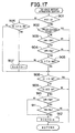
- Fig. 17 is a flowchart illustrating the try-again restart determining method executed by the ECU 51. This routine is started when the ignition switch is operated from the OFF position to the ON position.
- step 901 determines in step 901 whether the engine revolution speed NE is "0". If the engine revolution speed NE is not "0", the operation proceeds to step 906. In step 906, it is determined whether the starter signal STA is presently at the on-status. If the starter signal STA is at the on-status, the ECU 51 sets the try-again restart determination flag XGSTO to "1" in step 907, and proceeds step 908.
- step 901 determines whether the engine revolution speed NE is "0"
- step 902 determines whether the engine 1 is presently in the engine-stalled state. If the engine 1 is presently in the stalled state, the operation proceeds to step 908.
- step 903 determines in step 903 whether the present water temperature THW is substantially equal to the present fuel temperature THF. If the water temperature THW is not substantially equal to the fuel temperature THF, the operation proceeds to step 908. Conversely, if the water temperature THW and the fuel temperature THF are substantially equal, the operation proceeds to step 904.
- step 904 the ECU 51 determines whether the present water temperature THW is substantially equal to the present intake air temperature THA. If the water temperature THW is not substantially equal to the intake air temperature THA, the operation proceeds to step 908. Conversely, if the water temperature THW and the intake air temperature THA are substantially equal, the operation proceeds to step 905.
- step 905 the ECU 51 determines whether the starter signal STA is at the off-status. If the starter signal STA is at the on-status, the operation proceeds to step 907, where the try-again restart determination flag XGSTO is set to "1". The operation then proceeds to step 908.
- step 905 determines whether the starter signal STA is at the off-state. If it is determined in step 905 that the starter signal STA is at the off-state, the ECU 51 determines in step 908 whether the ignition switch is presently in the on-state. If the ignition switch is in the on-state, the ECU 51 temporarily ends this routine. Conversely, if the ignition switch is in the off-state, the operation proceeds to step 909.
- step 909 the ECU 51 determines whether the main relay MR is presently in the on-state. If the main relay MR is in the off-state, it is determined that a considerably long time has elapsed following the previous stop of the diesel engine 1. Therefore, the ECU 51 temporarily ends this routine. If the main relay MR is in the on-state, it means that the elapsed time following the switching of the ignition switch from the on-state to the off-state is not considerably long. Therefore, the ECU 51 proceeds to step 910, in order to execute an operation to be performed after the ignition switch has been turned off.
- step 910 the ECU 51 determines whether the present water temperature THW is substantially equal to the present fuel temperature THF. If they are not substantially equal, the ECU 51 temporarily ends this routine. Conversely, if the water temperature THW and the fuel temperature THF are substantially equal, the operation proceeds to step 911.
- step 911 the ECU 51 determines whether the present water temperature THW is substantially equal to the present intake air temperature THA. If they are not substantially equal, the ECU 51 temporarily ends this routine. Conversely, if the water temperature THW and the intake air temperature THA are substantially equal, the operation proceeds to step 912.
- step 912 the ECU 51 sets the try-again restart determination flag XGSTO to "0". Subsequently, the ECU 51 temporarily ends this routine.
- the embodiment detects the fuel pressure PC and calculates the target fuel pressure PFIN in the main routine before the cylinder discrimination. After the cylinder discrimination, the embodiment detects the fuel pressure PC and calculates the target fuel pressure PFIN in the engine speed interruption routine. However, it is also possible to determine in the main routine whether there is a time interruption or an engine speed interruption. In this modification, therefore, before the cylinder discrimination, the ECU 51 detects the fuel pressure PC and calculates the target fuel pressure PFIN in the time interruption routine. After the cylinder discrimination, the ECU 51 detects the fuel pressure PC and calculates the target fuel pressure PFIN in the engine speed interruption routine. It is also possible to perform the detection of the fuel pressure PC and the calculation of the target fuel pressure PFIN solely in the main routine, regardless of whether the cylinder discrimination has been completed.
- control of the fuel pressure PC is performed by controlling the relief valve 12, it is also possible to control the fuel pressure PC by controlling the pressure control valve 10 or the electromagnetic valve 3.
- the invention is embodied in the diesel engine 1, the invention is not limited to diesel engines, but may also be embodied in a gasoline engine.
- the invention achieves an excellent advantage of substantially preventing occurrence of loud combustion noises due to an excessively high fuel pressure in an accumulator pipe at the time of start of the engine.
Landscapes
- Engineering & Computer Science (AREA)
- Chemical & Material Sciences (AREA)
- Combustion & Propulsion (AREA)
- Mechanical Engineering (AREA)
- General Engineering & Computer Science (AREA)
- Oil, Petroleum & Natural Gas (AREA)
- Electrical Control Of Air Or Fuel Supplied To Internal-Combustion Engine (AREA)
- Fuel-Injection Apparatus (AREA)
Applications Claiming Priority (3)
| Application Number | Priority Date | Filing Date | Title |
|---|---|---|---|
| JP20918397 | 1997-08-04 | ||
| JP209183/97 | 1997-08-04 | ||
| JP20918397A JP3317202B2 (ja) | 1997-08-04 | 1997-08-04 | 蓄圧式エンジンの燃料噴射制御装置 |
Publications (3)
| Publication Number | Publication Date |
|---|---|
| EP0896145A2 EP0896145A2 (en) | 1999-02-10 |
| EP0896145A3 EP0896145A3 (en) | 2000-08-09 |
| EP0896145B1 true EP0896145B1 (en) | 2004-03-17 |
Family
ID=16568725
Family Applications (1)
| Application Number | Title | Priority Date | Filing Date |
|---|---|---|---|
| EP98114569A Expired - Lifetime EP0896145B1 (en) | 1997-08-04 | 1998-08-03 | Fuel injection control apparatus for accumulator type engine |
Country Status (3)
| Country | Link |
|---|---|
| EP (1) | EP0896145B1 (ja) |
| JP (1) | JP3317202B2 (ja) |
| DE (1) | DE69822380T2 (ja) |
Families Citing this family (20)
| Publication number | Priority date | Publication date | Assignee | Title |
|---|---|---|---|---|
| DE10031580A1 (de) * | 2000-06-29 | 2002-01-17 | Bosch Gmbh Robert | Druckgesteuertes Steuerteil für Common-Rail-Injektoren |
| JP3724392B2 (ja) * | 2001-07-26 | 2005-12-07 | トヨタ自動車株式会社 | 内燃機関の燃料噴射制御装置 |
| JP3786062B2 (ja) * | 2001-11-06 | 2006-06-14 | 株式会社デンソー | 蓄圧式燃料噴射装置 |
| DE10156637C1 (de) | 2001-11-17 | 2003-05-28 | Mtu Friedrichshafen Gmbh | Verfahren zur Steuerung und Regelung des Startbetriebs einer Brennkraftmaschine |
| KR100444051B1 (ko) * | 2001-12-27 | 2004-08-11 | 현대자동차주식회사 | 디젤 엔진의 냉간시동성 제어장치 |
| JP3988541B2 (ja) * | 2002-01-21 | 2007-10-10 | 株式会社デンソー | 蓄圧式燃料噴射装置 |
| JP2007092626A (ja) * | 2005-09-28 | 2007-04-12 | Iseki & Co Ltd | 作業機用エンジン |
| JP4572950B2 (ja) * | 2008-04-10 | 2010-11-04 | 株式会社デンソー | コモンレール圧制御装置およびそれを用いた燃料噴射システム |
| JP4857371B2 (ja) * | 2009-08-31 | 2012-01-18 | 日立オートモティブシステムズ株式会社 | エンジンの高圧燃料ポンプ制御装置 |
| EP2492480B1 (en) * | 2009-10-23 | 2015-11-25 | Bosch Corporation | Control device for internal combustion engine |
| EP2333283A1 (en) * | 2009-12-04 | 2011-06-15 | Perkins Engines Company Limited | A method and system for controlling pressure in a pressure accumulator |
| JP5131265B2 (ja) * | 2009-12-24 | 2013-01-30 | 株式会社デンソー | 燃料圧力制御装置 |
| JP5310624B2 (ja) * | 2010-03-26 | 2013-10-09 | 株式会社デンソー | 燃料圧力制御装置 |
| EP2565428A1 (en) * | 2010-04-27 | 2013-03-06 | Toyota Jidosha Kabushiki Kaisha | Controller for diesel engine |
| JP5333524B2 (ja) * | 2011-06-14 | 2013-11-06 | トヨタ自動車株式会社 | ディーゼルエンジンの始動制御装置 |
| JP5884744B2 (ja) * | 2013-02-05 | 2016-03-15 | 株式会社デンソー | 燃料供給装置 |
| JP5982536B2 (ja) * | 2015-06-23 | 2016-08-31 | 日立オートモティブシステムズ株式会社 | 内燃機関の高圧燃料ポンプ制御装置 |
| DE102016207297B3 (de) * | 2016-04-28 | 2017-10-19 | Mtu Friedrichshafen Gmbh | Verfahren zum Betrieb einer Brennkraftmaschine, Einrichtung zum Steuern und/oder Regeln einer Brennkraftmaschine, Einspritzsystem und Brennkraftmaschine |
| GB2578577A (en) * | 2018-10-30 | 2020-05-20 | Perkins Engines Co Ltd | Fuel system control |
| CN115450778B (zh) * | 2022-09-14 | 2024-01-09 | 一汽解放汽车有限公司 | 供油控制方法、装置、电子设备及存储介质 |
Citations (2)
| Publication number | Priority date | Publication date | Assignee | Title |
|---|---|---|---|---|
| JPS63266149A (ja) * | 1987-04-22 | 1988-11-02 | Toyota Motor Corp | 内燃機関の燃料噴射制御装置 |
| JPH08232703A (ja) * | 1995-02-23 | 1996-09-10 | Toyota Motor Corp | 燃料圧力制御装置 |
Family Cites Families (5)
| Publication number | Priority date | Publication date | Assignee | Title |
|---|---|---|---|---|
| AT380540B (de) * | 1982-02-12 | 1986-06-10 | Steyr Daimler Puch Ag | Kraftstoffeinspritzanlage fuer eine elektrische, ein startschloss umfassende anlasseinrichtung aufweisende kraftfahrzeug-dieselmotoren |
| GB2290112B (en) * | 1992-10-15 | 1996-03-27 | Fuji Heavy Ind Ltd | Starting system pressure control method for high pressure direct fuel injection engine |
| JP3360336B2 (ja) | 1993-01-12 | 2002-12-24 | 株式会社デンソー | 内燃機関の燃料噴射装置 |
| ATE215178T1 (de) * | 1994-05-06 | 2002-04-15 | Cummins Engine Co Inc | Verfahren und vorrichtung zur elektronischen steuerung eines speicherkraftstoffsystems |
| JPH09209180A (ja) | 1996-02-02 | 1997-08-12 | Fujikura Ltd | 銅又は銅合金材の防錆処理方法 |
-
1997
- 1997-08-04 JP JP20918397A patent/JP3317202B2/ja not_active Expired - Fee Related
-
1998
- 1998-08-03 EP EP98114569A patent/EP0896145B1/en not_active Expired - Lifetime
- 1998-08-03 DE DE1998622380 patent/DE69822380T2/de not_active Expired - Fee Related
Patent Citations (2)
| Publication number | Priority date | Publication date | Assignee | Title |
|---|---|---|---|---|
| JPS63266149A (ja) * | 1987-04-22 | 1988-11-02 | Toyota Motor Corp | 内燃機関の燃料噴射制御装置 |
| JPH08232703A (ja) * | 1995-02-23 | 1996-09-10 | Toyota Motor Corp | 燃料圧力制御装置 |
Also Published As
| Publication number | Publication date |
|---|---|
| JP3317202B2 (ja) | 2002-08-26 |
| EP0896145A3 (en) | 2000-08-09 |
| DE69822380D1 (de) | 2004-04-22 |
| DE69822380T2 (de) | 2005-02-24 |
| EP0896145A2 (en) | 1999-02-10 |
| JPH1150881A (ja) | 1999-02-23 |
Similar Documents
| Publication | Publication Date | Title |
|---|---|---|
| EP0896145B1 (en) | Fuel injection control apparatus for accumulator type engine | |
| US7822534B2 (en) | Fuel supply device and fuel supply method for internal combustion engine | |
| EP1846648B1 (en) | Control apparatus for internal combustion engine | |
| US7801672B2 (en) | After-stop fuel pressure control device of direct injection engine | |
| EP2010776B1 (en) | Start-up control device and start-up control method for internal combustion engine | |
| EP0886058B1 (en) | Fuel pressure control apparatus for fuel injection system of engine | |
| US6978763B2 (en) | Engine fuel injection device and engine fuel injection method | |
| JP2007285129A (ja) | 内燃機関の始動制御装置 | |
| JP3546285B2 (ja) | 蓄圧式エンジンの燃料噴射制御装置 | |
| JP2009079514A (ja) | 筒内噴射式内燃機関の燃圧制御装置 | |
| US20100018189A1 (en) | Control system of internal combustion engine | |
| JP3572937B2 (ja) | 蓄圧式燃料噴射機構の燃料圧制御装置 | |
| WO2003012275A1 (fr) | Commande d'injection de carburant dans un moteur a combustion interne | |
| JP2000248983A (ja) | 高圧燃料噴射系の燃料圧力制御装置 | |
| US20090038301A1 (en) | Secondary air supply device and method for internal combustion engine | |
| EP2357341B1 (en) | Internal combustion engine control unit | |
| JP2004036498A (ja) | 燃料噴射装置 | |
| JP3389848B2 (ja) | 蓄圧式燃料噴射装置 | |
| JP5477899B2 (ja) | 蓄圧式燃料噴射装置の制御装置及び制御方法並びに蓄圧式燃料噴射装置 | |
| JP3418996B2 (ja) | コモンレール式燃料噴射装置 | |
| JP3422220B2 (ja) | 蓄圧式エンジンの燃料噴射制御装置 | |
| JP2007092717A (ja) | 内燃機関用燃料供給装置 | |
| KR100521186B1 (ko) | 디젤 엔진 차량에서의 디젤 오일링 방지 방법 | |
| JP3932666B2 (ja) | 燃料噴射装置 | |
| JP3347653B2 (ja) | ディーゼル機関の燃料噴射制御装置 |
Legal Events
| Date | Code | Title | Description |
|---|---|---|---|
| PUAI | Public reference made under article 153(3) epc to a published international application that has entered the european phase |
Free format text: ORIGINAL CODE: 0009012 |
|
| 17P | Request for examination filed |
Effective date: 19980803 |
|
| AK | Designated contracting states |
Kind code of ref document: A2 Designated state(s): DE FR GB |
|
| AX | Request for extension of the european patent |
Free format text: AL;LT;LV;MK;RO;SI |
|
| PUAL | Search report despatched |
Free format text: ORIGINAL CODE: 0009013 |
|
| AK | Designated contracting states |
Kind code of ref document: A3 Designated state(s): AT BE CH CY DE DK ES FI FR GB GR IE IT LI LU MC NL PT SE |
|
| AX | Request for extension of the european patent |
Free format text: AL;LT;LV;MK;RO;SI |
|
| AKX | Designation fees paid |
Free format text: DE FR GB |
|
| 17Q | First examination report despatched |
Effective date: 20030116 |
|
| GRAH | Despatch of communication of intention to grant a patent |
Free format text: ORIGINAL CODE: EPIDOS IGRA |
|
| GRAS | Grant fee paid |
Free format text: ORIGINAL CODE: EPIDOSNIGR3 |
|
| GRAA | (expected) grant |
Free format text: ORIGINAL CODE: 0009210 |
|
| AK | Designated contracting states |
Kind code of ref document: B1 Designated state(s): DE FR GB |
|
| REG | Reference to a national code |
Ref country code: GB Ref legal event code: FG4D |
|
| REF | Corresponds to: |
Ref document number: 69822380 Country of ref document: DE Date of ref document: 20040422 Kind code of ref document: P |
|
| ET | Fr: translation filed | ||
| PLBE | No opposition filed within time limit |
Free format text: ORIGINAL CODE: 0009261 |
|
| STAA | Information on the status of an ep patent application or granted ep patent |
Free format text: STATUS: NO OPPOSITION FILED WITHIN TIME LIMIT |
|
| 26N | No opposition filed |
Effective date: 20041220 |
|
| PGFP | Annual fee paid to national office [announced via postgrant information from national office to epo] |
Ref country code: DE Payment date: 20080814 Year of fee payment: 11 |
|
| PGFP | Annual fee paid to national office [announced via postgrant information from national office to epo] |
Ref country code: FR Payment date: 20080818 Year of fee payment: 11 |
|
| PGFP | Annual fee paid to national office [announced via postgrant information from national office to epo] |
Ref country code: GB Payment date: 20080813 Year of fee payment: 11 |
|
| GBPC | Gb: european patent ceased through non-payment of renewal fee |
Effective date: 20090803 |
|
| REG | Reference to a national code |
Ref country code: FR Ref legal event code: ST Effective date: 20100430 |
|
| PG25 | Lapsed in a contracting state [announced via postgrant information from national office to epo] |
Ref country code: FR Free format text: LAPSE BECAUSE OF NON-PAYMENT OF DUE FEES Effective date: 20090831 Ref country code: DE Free format text: LAPSE BECAUSE OF NON-PAYMENT OF DUE FEES Effective date: 20100302 |
|
| PG25 | Lapsed in a contracting state [announced via postgrant information from national office to epo] |
Ref country code: GB Free format text: LAPSE BECAUSE OF NON-PAYMENT OF DUE FEES Effective date: 20090803 |