EP0875524A2 - Verbundmembranen - Google Patents
Verbundmembranen Download PDFInfo
- Publication number
- EP0875524A2 EP0875524A2 EP98302933A EP98302933A EP0875524A2 EP 0875524 A2 EP0875524 A2 EP 0875524A2 EP 98302933 A EP98302933 A EP 98302933A EP 98302933 A EP98302933 A EP 98302933A EP 0875524 A2 EP0875524 A2 EP 0875524A2
- Authority
- EP
- European Patent Office
- Prior art keywords
- composite membrane
- membrane according
- fibres
- porous substrate
- membrane
- Prior art date
- Legal status (The legal status is an assumption and is not a legal conclusion. Google has not performed a legal analysis and makes no representation as to the accuracy of the status listed.)
- Granted
Links
Images


Classifications
-
- H—ELECTRICITY
- H01—ELECTRIC ELEMENTS
- H01M—PROCESSES OR MEANS, e.g. BATTERIES, FOR THE DIRECT CONVERSION OF CHEMICAL ENERGY INTO ELECTRICAL ENERGY
- H01M8/00—Fuel cells; Manufacture thereof
- H01M8/10—Fuel cells with solid electrolytes
- H01M8/1016—Fuel cells with solid electrolytes characterised by the electrolyte material
- H01M8/1018—Polymeric electrolyte materials
- H01M8/1067—Polymeric electrolyte materials characterised by their physical properties, e.g. porosity, ionic conductivity or thickness
-
- C—CHEMISTRY; METALLURGY
- C08—ORGANIC MACROMOLECULAR COMPOUNDS; THEIR PREPARATION OR CHEMICAL WORKING-UP; COMPOSITIONS BASED THEREON
- C08J—WORKING-UP; GENERAL PROCESSES OF COMPOUNDING; AFTER-TREATMENT NOT COVERED BY SUBCLASSES C08B, C08C, C08F, C08G or C08H
- C08J5/00—Manufacture of articles or shaped materials containing macromolecular substances
- C08J5/20—Manufacture of shaped structures of ion-exchange resins
- C08J5/22—Films, membranes or diaphragms
- C08J5/2206—Films, membranes or diaphragms based on organic and/or inorganic macromolecular compounds
- C08J5/2275—Heterogeneous membranes
-
- H—ELECTRICITY
- H01—ELECTRIC ELEMENTS
- H01M—PROCESSES OR MEANS, e.g. BATTERIES, FOR THE DIRECT CONVERSION OF CHEMICAL ENERGY INTO ELECTRICAL ENERGY
- H01M8/00—Fuel cells; Manufacture thereof
- H01M8/02—Details
- H01M8/0289—Means for holding the electrolyte
-
- H—ELECTRICITY
- H01—ELECTRIC ELEMENTS
- H01M—PROCESSES OR MEANS, e.g. BATTERIES, FOR THE DIRECT CONVERSION OF CHEMICAL ENERGY INTO ELECTRICAL ENERGY
- H01M8/00—Fuel cells; Manufacture thereof
- H01M8/10—Fuel cells with solid electrolytes
- H01M8/1016—Fuel cells with solid electrolytes characterised by the electrolyte material
- H01M8/1018—Polymeric electrolyte materials
- H01M8/1058—Polymeric electrolyte materials characterised by a porous support having no ion-conducting properties
- H01M8/106—Polymeric electrolyte materials characterised by a porous support having no ion-conducting properties characterised by the chemical composition of the porous support
-
- H—ELECTRICITY
- H01—ELECTRIC ELEMENTS
- H01M—PROCESSES OR MEANS, e.g. BATTERIES, FOR THE DIRECT CONVERSION OF CHEMICAL ENERGY INTO ELECTRICAL ENERGY
- H01M8/00—Fuel cells; Manufacture thereof
- H01M8/10—Fuel cells with solid electrolytes
- H01M8/1016—Fuel cells with solid electrolytes characterised by the electrolyte material
- H01M8/1018—Polymeric electrolyte materials
- H01M8/1058—Polymeric electrolyte materials characterised by a porous support having no ion-conducting properties
- H01M8/1062—Polymeric electrolyte materials characterised by a porous support having no ion-conducting properties characterised by the physical properties of the porous support, e.g. its porosity or thickness
-
- C—CHEMISTRY; METALLURGY
- C08—ORGANIC MACROMOLECULAR COMPOUNDS; THEIR PREPARATION OR CHEMICAL WORKING-UP; COMPOSITIONS BASED THEREON
- C08J—WORKING-UP; GENERAL PROCESSES OF COMPOUNDING; AFTER-TREATMENT NOT COVERED BY SUBCLASSES C08B, C08C, C08F, C08G or C08H
- C08J2327/00—Characterised by the use of homopolymers or copolymers of compounds having one or more unsaturated aliphatic radicals, each having only one carbon-to-carbon double bond, and at least one being terminated by a halogen; Derivatives of such polymers
- C08J2327/02—Characterised by the use of homopolymers or copolymers of compounds having one or more unsaturated aliphatic radicals, each having only one carbon-to-carbon double bond, and at least one being terminated by a halogen; Derivatives of such polymers not modified by chemical after-treatment
- C08J2327/12—Characterised by the use of homopolymers or copolymers of compounds having one or more unsaturated aliphatic radicals, each having only one carbon-to-carbon double bond, and at least one being terminated by a halogen; Derivatives of such polymers not modified by chemical after-treatment containing fluorine atoms
- C08J2327/18—Homopolymers or copolymers of tetrafluoroethylene
-
- Y—GENERAL TAGGING OF NEW TECHNOLOGICAL DEVELOPMENTS; GENERAL TAGGING OF CROSS-SECTIONAL TECHNOLOGIES SPANNING OVER SEVERAL SECTIONS OF THE IPC; TECHNICAL SUBJECTS COVERED BY FORMER USPC CROSS-REFERENCE ART COLLECTIONS [XRACs] AND DIGESTS
- Y02—TECHNOLOGIES OR APPLICATIONS FOR MITIGATION OR ADAPTATION AGAINST CLIMATE CHANGE
- Y02E—REDUCTION OF GREENHOUSE GAS [GHG] EMISSIONS, RELATED TO ENERGY GENERATION, TRANSMISSION OR DISTRIBUTION
- Y02E60/00—Enabling technologies; Technologies with a potential or indirect contribution to GHG emissions mitigation
- Y02E60/10—Energy storage using batteries
-
- Y—GENERAL TAGGING OF NEW TECHNOLOGICAL DEVELOPMENTS; GENERAL TAGGING OF CROSS-SECTIONAL TECHNOLOGIES SPANNING OVER SEVERAL SECTIONS OF THE IPC; TECHNICAL SUBJECTS COVERED BY FORMER USPC CROSS-REFERENCE ART COLLECTIONS [XRACs] AND DIGESTS
- Y02—TECHNOLOGIES OR APPLICATIONS FOR MITIGATION OR ADAPTATION AGAINST CLIMATE CHANGE
- Y02E—REDUCTION OF GREENHOUSE GAS [GHG] EMISSIONS, RELATED TO ENERGY GENERATION, TRANSMISSION OR DISTRIBUTION
- Y02E60/00—Enabling technologies; Technologies with a potential or indirect contribution to GHG emissions mitigation
- Y02E60/30—Hydrogen technology
- Y02E60/50—Fuel cells
Definitions
- the present invention relates to a novel composite membrane which is of use in electrochemical devices, particularly fuel cells, and a process for the manufacture of the novel composite membrane.
- Electrochemical cells invariably comprise at their fundamental level a solid or liquid ion conducting electrolyte and two electrodes, the anode and cathode, at which the desired electrochemical reactions take place. Electrochemical cells may be found in a range of devices, for example fuel cells, batteries, sensors, electrodialysis reactors and electrolytic reactors for a diverse range of applications including the electrolysis of water, chemical synthesis, salt splitting, water purification, effluent treatment, and metal finishing among others.
- a fuel cell is an energy conversion device that efficiently converts the stored chemical energy of its fuel into electrical energy by combining either hydrogen, stored as a gas, or methanol stored as a liquid or gas, with oxygen to generate electrical power.
- the hydrogen or methanol are oxidised at the anode and oxygen is reduced at the cathode.
- Both electrodes are of the gas diffusion type.
- the electrolyte has to be in contact with both electrodes and may be acidic or alkaline, liquid or solid, in nature.
- the electrolyte is a solid ion conducting, or more specifically a proton conducting, polymer membrane, commonly based on copolymers of perfluorosulphonic acid and tetrafluoroethylene, and the combined structure formed from the membrane and the two gas diffusion electrodes is known as the membrane electrode assembly (MEA).
- MEA membrane electrode assembly
- solid ion conducting membrane electrolytes useful in fuel cells and other devices are selected from commercially available membranes, for example perfluorinated membranes sold under the trade names Nafion® (E.I. DuPont de Nemours and Co.), Aciplex® (Asahi Chemical Industry) and Flemion® (Asahi Glass KK).
- Nafion® E.I. DuPont de Nemours and Co.
- Aciplex® Aciplex®
- Flemion® Adsahi Glass KK
- the higher specific resistance of the above composite membrane means that in practice it has to be much thinner than the equivalent pure proton conducting membrane to maintain the same overall conductivity and thus cell performance.
- reducing the thickness of the composite membrane reduces the advantages that a composite membrane can provide. For example, there is a limit to the extent to which the thickness ofthe membrane can be reduced since as the membrane is made thinner, the durability and longevity can decrease, and reactant gas cross-over through the membrane is more liable to occur, both of which lead to a reduction in the cell performance.
- the problems associated with dimensional stability and handlability for MEA fabrication can be exacerbated with thinner membranes.
- E.I. DuPont de Nemours and Co. (WO95/16730) describe a process for making a reinforced substantially non-porous membrane with satisfactory mechanical strength and very low resistance to ionic conduction which approaches that of very thin, unreinforced perfluoro ion exchange polymer membranes.
- the composite membrane utilises a porous hydrocarbon substrate, such as a polyolefin, and on which at least one side is coated with an ion exchange film formed from a fluorinated polymer.
- a further object of the present invention is to provide a process for the manufacture of the composite membrane of the invention, in particular a process that is capable of producing composite membranes in high volumes and with high yields and at low unit cost, and preferably as a single continuous process.
- a still further object is to provide a process for preparing an MEA in high volumes and with high yields and at low unit cost.
- the present invention provides a composite membrane comprising a porous substrate of randomly orientated individual fibres and at least one ion conducting polymer, characterised in that the ion conducting polymer is embedded within the porous substrate.
- a composite membrane comprising a plurality of fibres randomly combined to form a porous substrate and at least one polymeric material, characterised in that the polymeric material is embedded within the porous substrate.
- the porous substrate typically has at least 50%, suitably at least 75% of the individual pore sizes being greater than 1 ⁇ m in at least one direction, although a porous substrate wherein some of the pores are less than 1 ⁇ m in all directions is within the scope of the invention.
- the total thickness of the membrane is less than 200 ⁇ m and preferably less than 100 ⁇ m.
- the fibres within the substrate are normally randomly orientated in the x and y direction (in-plane) producing a two dimensional isotropic structure. Additionally, random orientation in the z direction (through-plane) can be introduced with the inclusion of very short fibres, typically lengths of less than or equal to 0.2mm or very fine fibres, typically of diameters less than or equal to 1 ⁇ m.
- Fibres which are suitable for use in the present invention include glass, polymer, ceramic, quartz, silica, carbon or metal fibres. Fibres of carbon or metal would need to be electrically insulated prior to being formed into the membrane.
- the fibres are not polytetrafluoroethylene (PTFE) or polyethylene fibres.
- the fibres are of glass, ceramic, quartz, silica, carbon or metal and preferably of glass, ceramic, or quartz.
- the fibres are typically of diameters in the range of 0.1 ⁇ m to 50 ⁇ m, preferably of 0.2 ⁇ m to 20 ⁇ m and with lengths from 0.05mm to 300mm, suitably 0.5mm to 150mm.
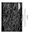
- Figure 1 shows a micrograph of a typical substrate formed from glass fibres containing only one diameter of glass fibre, obtained using a scanning electron microscope, and which clearly show a substrate of randomly orientated individual fibres lying in the x and y directions only.
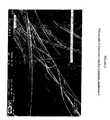
- Figure 2 shows a substrate with a range of fibre diameters with the finer fibres giving rise to fibres lying in the z direction.
- the ion conducting polymer is a proton conducting polymer, examples of such polymers being well known to those skilled in the art. More than one proton conducting polymer may be present and/or a non-proton conducting polymer may also be included in the novel membrane of the present invention.
- the proton conducting polymers suitable for use in the present invention may include, but are not limited to:
- polymeric materials which are not proton conducting polymers may be used in addition to or in place of a proton conducting polymer.
- such polymers can be used for applications requiring a bipolar membrane or a completely anion exchange membrane.
- Anion exchange polymers are generally based on quaternary ammonium groups, rather than the fixed sulphonic acid groups in proton conducting polymers. These include, for example, the tetraalkyl ammonium group (-N + R 3 ) and the quaternary ammonium centre in Tosflex® membranes (-N(R 1 )(CH 2 ) y N + (R 3 )) supplied by Tosoh.
- quaternary ammonium centre in Tosflex® membranes -N(R 1 )(CH 2 ) y N + (R 3 ) supplied by Tosoh.
- non-ion conducting polymeric materials may be used in addition to the one or more ion conducting or proton conducting polymers.
- non-ion conducting polymers include PTFE, FEP, PVDF, Viton® and hydrocarbon types such as polyethylene, polypropylene and polymethylmethacralate.
- the polymer is suitably applied to the fibres in the form of a solution, the solvents of which may be either organic or aqueous based.
- Solvents of all of the above polymers may include or may be modified to include, water, methanol and/or other aliphatic alcohols, ethers, acetone, tetrahydrofuran (THF), n-methylpyrrolidone (NMP), dimethyl sulphoxide (DMSO) dimethyl formamide (DMF) dimethyl acetamide (DMAc) or protonic solvents such as sulphuric acid or phosphoric acid and/or mixtures of the above.
- THF tetrahydrofuran
- NMP n-methylpyrrolidone
- DMSO dimethyl sulphoxide
- DMF dimethyl formamide
- DMAc dimethyl acetamide
- protonic solvents such as sulphuric acid or phosphoric acid and/or mixtures of the above.
- a first advantage of the present invention is that a free-standing, dimensionally stable composite membrane is produced resulting in greater handlability.
- the membrane of the invention is therefore also more amenable to high volume continuous production processes, as described hereinafter, due to the high dimensional stability of the underlying porous substrate.
- the high dimensional stability of the membrane enables thinner membranes to be produced which are more amenable to higher volume MEA manufacturing than state of the art thin membranes, which due to the exacerbated dimensional changes with increased levels of water content, are difficult to handle during MEA fabrication.
- a further advantage of the composite membrane of the present invention is that a composite membrane having both an intrinsic ionic conductivity and reactant gas cross-over essentially similar to the intrinsic conductivity and reactant gas cross-over shown by a non-reinforced ion conducting membrane of the same polymer, and of comparable thickness, is obtained.
- This demonstrates an advantage over composite membranes described in the literature where the thickness of the membrane has to be substantially reduced in order to obtain a reasonable conductivity.
- a further advantage of the present invention is the greater flexibility to tailor the characteristics of the membrane required for specific applications and/or conditions. It may be beneficial to coat the fibres with one or more different materials prior to forming the porous substrate to obtain additional characteristics required for specific applications. Fibres may be coated with ion exchange polymeric materials with different characteristics such as ion exchange capacity or equivalent weight (EW) and molecular weight in order to modify the water transport properties of the final membrane.
- EW equivalent weight
- the fibres may also be coated with other non ion-conducting polymers to change their surface characteristics, such as PTFE, FEP, PVDF, Viton® and hydrocarbon types such as polyethylene, polypropylene and polymethylmethacralate to make hydrophobic areas within the substrate, or amorphous silica to produce a more hydrophilic surface.
- the fibres may be catalysed with, for example platinum, to combine any reactant hydrogen and oxygen which can diffuse through the membrane (known as gas diffusion cross over), particularly the thinner membranes, and in which the product water so formed acts to enhance the humidification characteristics of the membrane.
- particulate materials within the membrane to increase either the sites available for proton migration and/or to increase the sites available for holding water within the substrate.
- Materials such as acidic alumina, silica, titanium dioxides, zirconium oxides, zirconium silicates, tungsten oxides, tin oxides and zeolites with a mean particle size of 0.001 ⁇ m to 10 ⁇ m, preferably 0.01 ⁇ m to 5 ⁇ m are examples of suitable particulates which may be used.
- the particulate material may first be coated, for example, with an ion conducting polymer, a non-conducting hydrophobic or hydrophilic polymer, or a catalyst.
- more that one type of fibre of differing characteristics are used and mixed together to form a homogenously mixed porous substrate.
- a laminated membrane comprising more than one polymer containing layer, at least one layer of which is a composite membrane of the invention.
- each layer may comprise either the same or different types of fibres and porous substrates and also the same or different types of polymeric material embedded within the porous substrate of each composite membrane layer.
- Composite membranes of the present invention are suitable for low cost manufacture.
- the membranes may be manufactured by one of two general methods.
- the membranes may be manufactured by taking a pre-formed porous substrate of randomly orientated individual fibres and thereafter applying the polymeric material. This can be done by any number of coating processes such as printing, rolling, K-bar, doctor blade methods, spraying or thin-film casting.
- a preferred method for the manufacture of the composite membrane of the present invention comprises forming a porous substrate of randomly orientated individual fibres by adapting a continuous manufacturing process and thereafter impregnating the substrate with polymeric material.
- the continuous manufacturing process may be based on paper-making technology, calendering or extrusion.
- the fibres are dispersed in water to form a dilute slurry and thereafter forming a continuous structure by the controlled deposition of said slurry onto a moving mesh bed, dewatering the solids and drying compaction of the fibres, followed by nip roller coating/filling of the substrate with a solution of the polymeric material and further compaction/drying of the membrane under a suitable time/pressure/temperature regime.
- a mixture of the fibres and a solution of a polymeric material may be extruded under controlled temperature/pressure to produce a sheet of the fibre/polymer composite membrane.
- the fibres may be pre-coated with one or more materials.
- particulate matter may be added to the fibre containing slurry and/or to the polymeric material. The particulate matter may first be coated with, for example, ion conducting polymer, non-conducting hydrophobic or hydrophilic polymer, or catalyst etc. The membrane is then formed by one of the continuous manufacturing processes described above.
- a major advantage of using a continuous manufacturing method such as conventional paper making techniques is that the composite membrane is easily manufactured in a fewer number of steps than prior art composite membranes, thus making it more cost effective and commercially viable.
- the membrane may also be produced in continuous lengths of many metres, and widths of equal to or greater than one metre, and in a very cost effective manner.
- the present invention also relates to a membrane electrode assembly and a method for the manufacture thereof wherein the composite membrane is according to the present invention.
- a still further aspect of the present invention relates to a fuel cell and a method for the manufacture thereof comprising a composite membrane of the present invention.
- a further advantage is that it is possible to combine a membrane of the present invention with one or more electrode layers as described in commonly owned European patent application EP 0 791 974 to form a membrane electrode assembly at the same rate as each individual component could be produced.
- the present invention is not limited to the use of the composite membrane in a fuel cell and any electrochemical device which comprises a composite membrane of the invention is within the scope.
- a pre-formed non-woven glass fibre substrate of density 0.2g/cm 3 (provided by Technical Fibre Products, Kendal, Cumbria, UK as 10g/m 2 glass tissue Optimat 201), was placed on a sheet of sintered PTFE, and a solution of perfluorosulphonic acid in the aqueous form as described in EP 0 731 520 was applied to the glass fibre tissue.
- a pre-formed non-woven glass microfibre substrate of density 0.25g/cm 3 (provided as a 15g/m 2 glass mat supplied as "Supercool M” from Technical Fibre Products, Kendal, Cumbria, UK), was applied to the glass tissue/aqueous Nafion® layer and a further layer of the Optimat 201 glass tissue laid on top.
- the substrate was filled with the aqueous Nafion® to achieve a total solid Nafion® loading of 13,0mg/cm 2 , and dried in air at ambient room temperature, to produce a robust and handleable composite membrane with a thickness of 180 ⁇ m.
- the composite membrane 1 was formed into a MEA using a carbon supported platinum/ruthenium catalyst containing electrode (0.25mg Pt/cm 2 ) as the anode, and a carbon supported platinum catalyst containing electrode (0.60mg Pt/cm 2 ) as the cathode.
- An evaluation of the MEA comprising composite membrane 1 was performed in a complete single fuel cell.
- the polarisation plot of voltage as a function of current density for the MEA was determined at a cell temperature of 80°C with H 2 /air as reactants, each at a pressure of 30 psig (pounds per square inch gauge), and reactant stoichiometries of 1.5 for H 2 and 2.0 for air.
- a mixture of chopped glass fibres (Type A20 BC, from Schuller International Group Inc., PO Box 5108, Denver, Co 80217), of a fibre length of 12mm (0.267g), and glass microfibre (Evanite 608 from Evanite Fibre Corporation, Covallis, Oregon, USA) (0.533g) were dispersed with mixing in demineralised water (500 cm 3 ).
- a non-woven substrate of the invention was fabricated from the resulting mixture in a single step process based on the principles of paper-making technology, as a sheet size of 214 cm 2 in a standard SCA sheet former (AB Lorentzen & Wettre, Box 4, S-163 93 Sweden). The sheet was air dried at 100°C. A micrograph of the sheet obtained is illustrated in Figure 2.
- the non-woven glass fibre substrate was placed on a sheet of sintered PTFE and a solution of perfluorosulphonic acid in the aqueous form as described in EP 0 731 520 was applied to the glass fibre matrix.
- the structure was filled with the aqueous solution of Nafion® to achieve a total solid Nafion® loading of 11.2mg/cm 2 , and a membrane thickness of 70 ⁇ m.
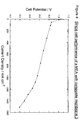
- Composite membrane 2 was formed into a membrane electrode assembly (MEA) as described in Example 1 and evaluated in the fuel cell at a cell temperature of 80 °C with H 2 /O 2 as reactants, each at a pressure of 30 psig, and reactant stoichiometries of 1.5 for H 2 and 10.0 for O 2 .
- the cell potential versus current density plot is shown in Figure 3. This demonstrates that good cell performances were obtained from the MEA comprising the composite membrane of the invention.
- a mixture of chopped glass fibres (Type A20 BC, from Schuller International Group Inc., PO Box 5108, Denver, Co 80217), of a fibre length of 12mm (0.7g) and glass microfibre (Evanite 608 from Evanite Fibre Corporation, Covallis, Oregon, USA) (1.4g) were dispersed with mixing in demineralised water (500 cm 3 ).
- a non-woven substrate ofthe invention was fabricated from the resulting mixture in a single step process based on the principles of paper-making technology, as a sheet size of 330mm diameter (855.3cm 2 ) in a custom built sheet former (similar in general operation to the sheetmaker used in Example 2). The sheet was air dried at 105°C.
- the substrate was sprayed with a 5% solution of Nafion®, 1100 EW in lower aliphatic alcohols (Solutions Technologies Inc., Mendenhall, PA 19357, USA) to give a dry Nafion® loading of 0.42mg/cm 2 .
- the pre-coated substrate was placed on a sheet of sintered PTFE and a solution of perfluorosulphonic acid in the aqueous form as described in EP 0 731 520 was applied to the glass fibre substrate.
- the substrate was filled with the aqueous Nafion® to achieve a total solid Nafion® loading of 18.04mg/cm 2 , when fully dry. After applying pressure at a temperature in excess of 150°C, the final membrane thickness was 59 ⁇ m.
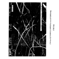
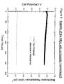
- Composite membrane 3 was formed into a MEA and evaluated in the fuel cell at a cell temperature of 80 °C with H 2 /air as reactants, each at a pressure of 30 psig, and reactant stoichiometries of 1.5 for H 2 and 2.0 for air.
- the cell potential versus current density plot is shown in Figure 4 and the performance is comparable with prior art MEAs employing non reinforced membranes of similar thickness, such as Nafion® 112.
- a mixture of chopped glass fibres (Type A20 BC, from Schuller International Group Inc., PO Box 5108, Denver, Co 80217), of a fibre length of 12mm (0.18g) and glass microfibre (Evanite 608 from Evanite Fibre Corporation, Covallis, Oregon, USA) (0.37g) were dispersed with mixing in demineralised water (500 cm 3 ).
- a non-woven substrate of the invention was fabricated from the resulting mixture in a single step process based on the principles of paper-making technology, as a sheet size of 330mm diameter (855.3cm 2 ) in a custom built sheet former (similar in general operation to the sheetmaker used in Example 2). The substrate was air dried at 105°C. This gave a substrate thickness of about 25 ⁇ m.
- a micrograph of the substrate obtained is given in Figure 5.
- the non-woven substrate was sprayed with a 5% solution of Nafion®, 1100 EW in lower aliphatic alcohols (Solutions Technologies Inc., Mendenhall, PA 19357, USA) to give a dry Nafion® loading of 0.24mg/cm 2 .
- the pre-coated, glass fibre substrate was placed on a sheet of sintered PTFE and a solution of perfluorosulphonic acid in the aqueous form as described in EP 0 731 520 was applied to thc glass fibre substrate.
- the substrate was filled with the aqueous Nafion® to achieve a total solid Nafion® loading of 4.7mg/cm 2 , when fully dry. This produced a robust and handleable composite membrane of 25 ⁇ m thickness.
- the laminated composite membrane 4 was formed into a MEA and evaluated in the fuel cell at a cell temperature of 80 °C with H 2 /air as reactants, each at a pressure of 30 psig, and reactant stoichiometries of 1.5 for H 2 and 2.0 for air.
- the cell potential versus current density plot is shown in Figure 6 and the performance is comparable with prior art MEAs employing non reinforced membranes of similar thickness, such as Nafion® 112.
- a quartz microfibre was obtained by placing quartz microfibre filters, (Type QM-A available from Whatman International Ltd, Maidstone, UK) in hot water and dispersing them using a high speed mechanical paddle stirrer. The fibres were then filtered and dried.
- the quartz microfibre (0.61g) was dispersed with mixing in demineralised water (500 cm 3 ).
- a substrate of the invention was fabricated from the resulting mixture in a single step process based on the principles of paper-making technology, as a sheet size of 330mm diameter (855.3cm 2 ) in a custom built sheet former (similar in general operation to the sheetmaker used in Example 2).
- the substrate was air dried at 105°C. This gave a substrate thickness of about 45 ⁇ m.
- the non-woven substrate was sprayed with a 5% solution of Nafion®, 1100 EW in lower aliphatic alcohols (Solutions Technologies Inc., Mendenhall, PA 19357, USA) to give a dry Nafion® loading of 0.33mg/cm 2 .
- the pre-coated, non-woven quartz fibre substrate was placed on a sheet of sintered PTFE and a solution of perfluorosulphonic acid in the aqueous form as described in EP 0 731 520 was applied to the quartz fibre substrate.
- the substrate was filled with the aqueous Nafion® to achieve a total solid Nafion® loading of 4.8 mg/cm 2 , when fully dry.
- the laminated composite membrane 5 was formed into a MEA and evaluated in the fuel cell at a cell temperature of 80 °C with H 2 /air as reactants, each at a pressure of 30 psig, and reactant stoichiometries of 1.5 for H 2 and 2.0 for air.
- the cell potential versus current density plot is shown in Figure 7 and the performance is comparable with prior art MEAs employing non reinforced membranes of similar thickness, such as Nafion® 1135.
- Figure 8 shows that after 500 hours of continuous fuel cell operation the MEA demonstrates a stable cell potential. Further, Figure 8 also shows measurement of the membrane resistance with time and this demonstrates that the membrane resistance was essentially unchanged from 0.113 ⁇ cm 2 at the beginning of the test to 0.112 ⁇ cm 2 after 500 hours operation.
- the composite membrane of the invention shows excellent stability in the PEMFC environment.
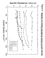
- the specific resistance of a membrane is given by the ratio of the area membrane resistance ( ⁇ cm 2 ) to the membrane thickness (cm) and is used to compare the intrinsic resistance of membranes of different thickness.
- the specific resistance of the composite membrane of this invention and of the state of the art pure unreinforced Nafion® membranes was measured in MEAs prepared as detailed in Example 1 by using the current-interrupt technique to measure the in-situ membrane resistance in the fuel cell and by dividing by the membrane thickness in the MEAs as measured from electron probe microanalysis (EPMA) micrographs.
- Figure 9 shows the plot of specific resistance versus the current density produced by the MEA. This shows that the composite membranes of this invention have a comparable specific resistance to the pure Nafion® family of membranes.
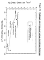
- membranes for the PEMFC do not show excessive rates of gas cross-over of H 2 from anode to cathode and of O 2 from cathode to anode. Due to the higher rate of H 2 diffusion it is generally more problematical than O 2 diffusion through the membrane.
- the rate of H 2 gas cross-over through the membrane in the MEAs described in Example 7 was measured in the fuel cell while it was not generating electrical energy ie under open circuit conditions. Rather than air or O 2 , inert N 2 gas (deoxygenated) was passed into the cathode of the fuel cell and H 2 into the anode of the fuel cell.
- FIG. 10 shows the resultant plot of H 2 gas cross-over versus membrane thickness for the MEAs. This shows that the composite membranes of this invention show comparable rates of gas cross-over to the pure Nafion® membranes.
- the rate of gas cross-over through the composite membrane of this invention amounts to less than 0.01% of the H 2 being fed to the anode.
- the composite membrane of this invention is gas tight.
Landscapes
- Chemical & Material Sciences (AREA)
- Engineering & Computer Science (AREA)
- Manufacturing & Machinery (AREA)
- Chemical Kinetics & Catalysis (AREA)
- General Chemical & Material Sciences (AREA)
- Life Sciences & Earth Sciences (AREA)
- Sustainable Development (AREA)
- Sustainable Energy (AREA)
- Electrochemistry (AREA)
- Medicinal Chemistry (AREA)
- Materials Engineering (AREA)
- Health & Medical Sciences (AREA)
- Inorganic Chemistry (AREA)
- Polymers & Plastics (AREA)
- Organic Chemistry (AREA)
- Fuel Cell (AREA)
- Manufacture Of Macromolecular Shaped Articles (AREA)
- Laminated Bodies (AREA)
- Filtering Materials (AREA)
- Catalysts (AREA)
- Inert Electrodes (AREA)
- Separation Using Semi-Permeable Membranes (AREA)
- Treatments Of Macromolecular Shaped Articles (AREA)
- Manufacture Of Porous Articles, And Recovery And Treatment Of Waste Products (AREA)
- Cell Separators (AREA)
- Glass Compositions (AREA)
Applications Claiming Priority (2)
| Application Number | Priority Date | Filing Date | Title |
|---|---|---|---|
| GBGB9708365.3A GB9708365D0 (en) | 1997-04-25 | 1997-04-25 | Proton conducting membranes |
| GB9708365 | 1997-04-25 |
Publications (3)
| Publication Number | Publication Date |
|---|---|
| EP0875524A2 true EP0875524A2 (de) | 1998-11-04 |
| EP0875524A3 EP0875524A3 (de) | 1999-04-07 |
| EP0875524B1 EP0875524B1 (de) | 2002-04-03 |
Family
ID=10811324
Family Applications (1)
| Application Number | Title | Priority Date | Filing Date |
|---|---|---|---|
| EP98302933A Expired - Lifetime EP0875524B1 (de) | 1997-04-25 | 1998-04-16 | Verbundmembranen |
Country Status (9)
| Country | Link |
|---|---|
| US (1) | US6042958A (de) |
| EP (1) | EP0875524B1 (de) |
| JP (1) | JPH10312815A (de) |
| AT (1) | ATE215581T1 (de) |
| CA (1) | CA2235193C (de) |
| DE (1) | DE69804526T2 (de) |
| DK (1) | DK0875524T3 (de) |
| ES (1) | ES2175616T3 (de) |
| GB (1) | GB9708365D0 (de) |
Cited By (37)
| Publication number | Priority date | Publication date | Assignee | Title |
|---|---|---|---|---|
| WO2000023510A1 (en) * | 1998-10-16 | 2000-04-27 | Johnson Matthey Public Limited Company | Substrate |
| WO2000024074A1 (en) * | 1998-10-16 | 2000-04-27 | Johnson Matthey Public Limited Company | Process for preparing a solid polymer electrolyte membrane |
| WO2000047816A1 (en) * | 1999-02-15 | 2000-08-17 | Johnson Matthey Public Limited Company | Nonwoven web |
| WO2000055933A1 (en) * | 1999-03-16 | 2000-09-21 | Johnson Matthey Public Limited Company | Gas diffusion substrates |
| EP1063716A2 (de) * | 1999-06-22 | 2000-12-27 | Johnson Matthey Public Limited Company | Kohlenstofffasern enthaltendes nicht-gewobenes Faservlies verwendbar als Gasdiffusionselektrodensubstrat für Brennstoffzellen |
| EP1063334A1 (de) * | 1999-06-22 | 2000-12-27 | Johnson Matthey Public Limited Company | Vliesstoffe |
| WO2001069706A1 (en) * | 2000-03-17 | 2001-09-20 | Johnson Matthey Public Limited Company | Proton conducting polymer membrane for electrochemical cell |
| WO2002022336A1 (es) * | 2000-09-13 | 2002-03-21 | David Fuel Cell Components, S.L. | Método para la fabricación de materiales compuestos |
| US6479188B1 (en) | 1999-10-13 | 2002-11-12 | The Gillette Company | Cathode tube and method of making the same |
| WO2003069711A2 (de) * | 2002-02-13 | 2003-08-21 | Creavis Gesellschaft Für Technologie Und Innovation Mbh | Flexible elektrolytmembran auf basis eines glasgewebes, verfahren zu deren herstellung und die verwendung derselben |
| WO2003073545A2 (de) * | 2002-02-26 | 2003-09-04 | Creavis Gesellschaft Für Technologie Und Innovation Mbh | Flexible elektrolytmembran auf basis eines polymerfasern umfassenden trägers, verfahren zu deren herstellung und die verwendung derselben |
| EP1359634A2 (de) * | 2002-05-03 | 2003-11-05 | Johnson Matthey Public Limited Company | Verbundmembran |
| US6689501B2 (en) | 2001-05-25 | 2004-02-10 | Ballard Power Systems Inc. | Composite ion exchange membrane for use in a fuel cell |
| FR2850300A1 (fr) * | 2003-01-23 | 2004-07-30 | Commissariat Energie Atomique | Materiau hybride organique-inorganique conducteur comprenant une phase mesoporeuse, membrane, electrode, et pile a combustible |
| EP1477515A1 (de) * | 2002-02-15 | 2004-11-17 | Toyo Boseki Kabushiki Kaisha | Clusterionenaustauschmembran und elektrolytmembran-elektrode-verbindungskörper |
| WO2005086265A1 (ja) * | 2004-03-04 | 2005-09-15 | Nippon Sheet Glass Company, Limited | プロトン伝導性膜用補強材およびそれを用いたプロトン伝導性膜および燃料電池 |
| WO2007034233A1 (en) * | 2005-09-23 | 2007-03-29 | Johnson Matthey Public Limited Company | Process for preparing a composite membrane |
| DE10392896B4 (de) * | 2002-07-09 | 2009-07-23 | General Motors Corp. (N.D.Ges.D. Staates Delaware), Detroit | Beständige Protonenaustauschmembran für eine Brennstoffzelle mit geringer Befeuchtung und Verfahren zur Herstellung einer Protonenaustauschmembran |
| CN101320818B (zh) * | 2008-07-15 | 2010-06-09 | 山东东岳神舟新材料有限公司 | 一种纤维增强多层含氟离子交换膜 |
| US7851095B2 (en) | 2004-05-26 | 2010-12-14 | Johnson Matthey Public Limited Company | Anode structure |
| CN101319051B (zh) * | 2008-07-15 | 2010-12-29 | 山东东岳神舟新材料有限公司 | 一种纤维增强无机物掺杂多层含氟离子交换膜 |
| US7923066B2 (en) | 2003-01-23 | 2011-04-12 | Commissariat A L'energie Atomique | Organic-inorganic hybrid material comprising a mineral mesoporous phase and an organic phase, a membrane and fuel cell |
| US8133306B2 (en) | 2004-06-15 | 2012-03-13 | Johnson Matthey Public Limited Company | Gas diffusion substrate |
| US8173324B2 (en) | 2007-07-25 | 2012-05-08 | Johnson Matthey Public Limited Company | Catalyst |
| US20120202099A1 (en) * | 2011-02-08 | 2012-08-09 | United Technologies Corporation | Flow battery having a low resistance membrane |
| US8318373B2 (en) | 2006-09-11 | 2012-11-27 | Johnson Matthey Fuel Cells Limited | Fuel cell assembly |
| US8367266B2 (en) | 2007-06-20 | 2013-02-05 | Johnson Matthey Fuel Cells Limited | Catalyst layer |
| US8399145B2 (en) | 2007-09-25 | 2013-03-19 | Johnson Matthey Fuel Cells Limited | Membrane electrode assembly |
| WO2013045894A1 (en) | 2011-09-28 | 2013-04-04 | Johnson Matthey Fuel Cells Limited | Carbon supported catalyst |
| WO2013057483A1 (en) | 2011-10-19 | 2013-04-25 | Johnson Matthey Fuel Cells Limited | Gas diffusion substrate |
| EP2650947A4 (de) * | 2010-12-10 | 2014-05-21 | Dalian Chemical Physics Inst | Verwendung einer porösen membran und verbundmembran daraus bei einer redox-flow-speicherbatterie |
| US9083012B2 (en) | 2004-09-24 | 2015-07-14 | Johnson Matthey Fuel Cells Limited | Membrane electrode assembly having an adhesive layer impregnating through an electrocatalyst layer and into a first gas diffusion substrate |
| US9847533B2 (en) | 2005-09-26 | 2017-12-19 | W.L. Gore & Associates, Inc. | Solid polymer electrolyte and process for making same |
| EP3382783A4 (de) * | 2015-11-26 | 2019-05-08 | LG Chem, Ltd. | Polymerelektrolytmembran, membranelektrodenanordnung damit und brennstoffzelle mit membranelektrodenanordnung |
| US10424795B2 (en) | 2014-02-05 | 2019-09-24 | Technical Fibre Products Limited | Gas diffusion substrate |
| CN110448958A (zh) * | 2019-07-25 | 2019-11-15 | 天津大学 | 纤维增强型多孔炭基电催化滤料的制备方法 |
| WO2023105229A3 (en) * | 2021-12-08 | 2023-07-20 | Johnson Matthey Hydrogen Technologies Limited | Method of manufacturing an ion-conducting membrane |
Families Citing this family (67)
| Publication number | Priority date | Publication date | Assignee | Title |
|---|---|---|---|---|
| US6495209B1 (en) | 1998-02-20 | 2002-12-17 | Lynntech, Inc. | Process of making a composite membrane |
| US20040209965A1 (en) * | 1998-10-16 | 2004-10-21 | Gascoyne John Malcolm | Process for preparing a solid polymer electrolyte membrane |
| US20040266299A1 (en) * | 1998-10-16 | 2004-12-30 | Fongalland Dharshini Chryshatha | Substrate |
| US20040208993A1 (en) * | 1998-10-16 | 2004-10-21 | Fongalland Dharshini Chryshantha | Substrate binder |
| DE19919988A1 (de) * | 1999-04-30 | 2000-11-02 | Univ Stuttgart | Protonenleitende Keramik-Polymer-Kompositmembran für den Temperaturbereich bis 300 DEG C |
| DE19919881A1 (de) * | 1999-04-30 | 2000-11-02 | Univ Stuttgart | Organisch-Anorganische Komposites und Kompositmembranen aus Ionomeren oder Ionomerblends und aus Schicht- oder Gerätsilicaten |
| US6860976B2 (en) * | 2000-06-20 | 2005-03-01 | Lynntech International, Ltd. | Electrochemical apparatus with retractable electrode |
| DE10033594B4 (de) * | 2000-07-11 | 2006-07-06 | Nucellsys Gmbh | Brennstoffzelle und Verwendung derselben in einem Kraftfahrzeug |
| IT1319649B1 (it) * | 2000-11-14 | 2003-10-23 | Nuvera Fuel Cells Europ Srl | Assieme membrana-elettrodo per cella a combustibile a membranapolimerica. |
| ATE439148T1 (de) * | 2000-12-12 | 2009-08-15 | Tersano Inc | Vorrichtung zur erzeugung und applikation von ozonisiertem wasser |
| US20020127474A1 (en) * | 2001-01-09 | 2002-09-12 | E.C.R.-Electro-Chemical Research Ltd. | Proton-selective conducting membranes |
| KR100403754B1 (ko) * | 2001-06-19 | 2003-10-30 | 송민규 | 연료전지용 복합 고분자 전해질 막, 이의 제조방법 및이를 포함하는 연료전지 |
| JP4052005B2 (ja) * | 2001-12-20 | 2008-02-27 | 住友化学株式会社 | 高分子電解質膜の製造法 |
| KR100441376B1 (ko) * | 2002-01-31 | 2004-07-23 | (주)퓨얼셀 파워 | 얇은 두께를 갖는 콤포지트 멤브레인 |
| US20050053818A1 (en) * | 2002-03-28 | 2005-03-10 | Marc St-Arnaud | Ion exchange composite material based on proton conductive functionalized inorganic support compounds in a polymer matrix |
| JP3873825B2 (ja) * | 2002-06-26 | 2007-01-31 | 株式会社デンソー | 燃料電池およびその製造方法 |
| GB0216834D0 (en) * | 2002-07-19 | 2002-08-28 | Accentus Plc | Porous polymeric membrane |
| US6630265B1 (en) | 2002-08-13 | 2003-10-07 | Hoku Scientific, Inc. | Composite electrolyte for fuel cells |
| JP3891484B2 (ja) * | 2002-09-05 | 2007-03-14 | 株式会社ノリタケカンパニーリミテド | 電解質膜およびその膜を備えた燃料電池 |
| TW558833B (en) * | 2002-09-09 | 2003-10-21 | Ind Tech Res Inst | Gas diffusion electrode and the method for making the same |
| US20040053100A1 (en) * | 2002-09-12 | 2004-03-18 | Stanley Kevin G. | Method of fabricating fuel cells and membrane electrode assemblies |
| DE10262009A1 (de) * | 2002-10-29 | 2004-05-19 | Daimlerchrysler Ag | Polymerelektrolytmembran-Brennstoffzelle mit einer verstärkten Polymerelektrolytmembran |
| US20040086774A1 (en) * | 2002-11-05 | 2004-05-06 | Munoz Beth C. | Gas diffusion electrodes |
| US20040110050A1 (en) * | 2002-12-09 | 2004-06-10 | Abd Elhamid Mahmoud H | Environmentally friendly and inexpensive dielectric coolant for fuel cell stacks |
| US20040157101A1 (en) * | 2003-02-11 | 2004-08-12 | Smedley Stuart I. | Fuel cell electrode assembly |
| US7229712B2 (en) * | 2003-03-07 | 2007-06-12 | Microcell Corporation | Fuel cell structures and assemblies |
| GB0319780D0 (en) | 2003-08-22 | 2003-09-24 | Johnson Matthey Plc | Membrane electrode assembly |
| US6962959B2 (en) | 2003-08-28 | 2005-11-08 | Hoku Scientific, Inc. | Composite electrolyte with crosslinking agents |
| US7695843B2 (en) * | 2004-02-13 | 2010-04-13 | Microcell Corporation | Microfibrous fuel cell assemblies comprising fiber-supported electrocatalyst layers, and methods of making same |
| US7422813B2 (en) * | 2004-06-08 | 2008-09-09 | Microcell Corporation | Fuel cell systems comprising microfibrous fuel cell elements and methods of making and using same |
| JP4613528B2 (ja) | 2004-06-24 | 2011-01-19 | コニカミノルタホールディングス株式会社 | プロトン伝導性電解質膜とその製造方法、及び該プロトン伝導性電解質膜を用いた固体高分子型燃料電池 |
| KR100658739B1 (ko) * | 2004-06-30 | 2006-12-15 | 삼성에스디아이 주식회사 | 연료전지용 고분자 전해질막 및 그 제조방법 |
| KR100637486B1 (ko) * | 2004-06-30 | 2006-10-20 | 삼성에스디아이 주식회사 | 연료전지용 전해질막 및 이를 포함하는 연료전지 |
| JPWO2006057239A1 (ja) * | 2004-11-26 | 2008-06-05 | 日本板硝子株式会社 | プロトン伝導性膜およびそれを用いた燃料電池、ならびにプロトン伝導性膜の製造方法 |
| KR101135477B1 (ko) * | 2005-01-12 | 2012-04-19 | 삼성에스디아이 주식회사 | 다공성 멤브레인 및 그 제조방법, 이를 이용한 연료전지용고분자 전해질막, 및 이를 포함하는 연료전지 시스템 |
| KR101135479B1 (ko) * | 2005-01-26 | 2012-04-13 | 삼성에스디아이 주식회사 | 연료전지용 고분자 전해질막, 이의 제조방법, 및 이를포함하는 연료전지 시스템 |
| EP1691440A1 (de) | 2005-02-07 | 2006-08-16 | Fuji Photo Film Co., Ltd. | Festelektrolyt, Methode zur Herstellung des Festelektrolyten, Membran, Membran-Elektrodeneinheit und Brennstoffzelle enthaltend den Festelektrolyten |
| JP5093870B2 (ja) | 2005-07-07 | 2012-12-12 | 富士フイルム株式会社 | 固体電解質複層フィルムの製造方法 |
| JP5044132B2 (ja) | 2005-07-07 | 2012-10-10 | 富士フイルム株式会社 | 固体電解質フィルムの製造方法及び製造設備 |
| KR100766896B1 (ko) * | 2005-11-29 | 2007-10-15 | 삼성에스디아이 주식회사 | 연료 전지용 고분자 전해질 막 및 이를 포함하는 연료 전지시스템 |
| JP4791822B2 (ja) * | 2005-12-28 | 2011-10-12 | 株式会社東芝 | 電解質膜、その製造方法、膜電極複合体及びそれを用いた燃料電池 |
| IL172944A (en) * | 2006-01-02 | 2011-12-29 | Univ Ben Gurion | Membrane for fuel cells |
| CN101507032B (zh) * | 2006-08-28 | 2012-03-07 | 丰田自动车株式会社 | 燃料电池用补强型电解质膜、其制造方法、燃料电池用膜-电极接合体和具备该接合体的固体高分子型燃料电池 |
| WO2008041622A1 (fr) | 2006-09-29 | 2008-04-10 | Fujifilm Corporation | Ensemble membrane électrode et procédé de production de celui-ci |
| JP2008091187A (ja) * | 2006-10-02 | 2008-04-17 | Hitachi Ltd | 燃料電池用電解質膜および、膜電極接合体,燃料電池 |
| FR2918799B1 (fr) * | 2007-07-10 | 2010-10-08 | Commissariat Energie Atomique | Substrat poreux etanche pour piles a combustible planaires et packaging integre. |
| JP5094295B2 (ja) | 2007-09-10 | 2012-12-12 | 富士フイルム株式会社 | 膜電極接合体および燃料電池 |
| JP2009070631A (ja) | 2007-09-11 | 2009-04-02 | Fujifilm Corp | 電解質膜、膜電極接合体および膜電極接合体を用いた燃料電池 |
| JP5068610B2 (ja) | 2007-09-11 | 2012-11-07 | 富士フイルム株式会社 | イオン性ポリマー粒子分散液およびその製造方法 |
| KR20100045501A (ko) * | 2007-09-19 | 2010-05-03 | 유티씨 파워 코포레이션 | 고 열전도도 전극 기판 |
| WO2009116630A1 (ja) | 2008-03-21 | 2009-09-24 | 旭硝子株式会社 | 固体高分子形燃料電池用膜電極接合体および固体高分子形燃料電池 |
| JP5277740B2 (ja) * | 2008-06-10 | 2013-08-28 | 旭硝子株式会社 | 触媒層の形成方法および固体高分子形燃料電池用膜電極接合体の製造方法 |
| CN101764232B (zh) * | 2008-11-14 | 2012-07-04 | 山东东岳高分子材料有限公司 | 具有交联网络结构的含氟质子交换膜及其制备 |
| JP5163439B2 (ja) * | 2008-11-19 | 2013-03-13 | Tdk株式会社 | 繊維含有高分子膜及びその製造方法、並びに、電気化学デバイス及びその製造方法 |
| CN101728551B (zh) * | 2009-12-10 | 2011-06-08 | 山东东岳神舟新材料有限公司 | 一种增强多层含氟离子交换膜 |
| US9017899B2 (en) | 2010-06-18 | 2015-04-28 | Shandong Huaxia Shenzhou New Material Co., Ltd. | Fluorine containing ionomer composite with ion exchange function, preparation method and use thereof |
| JP5638692B2 (ja) | 2010-06-18 | 2014-12-10 | シャンドン・フアシャ・シェンゾウ・ニュー・マテリアル・カンパニー・リミテッド | イオン交換機能を有する複合体並びにその調製方法及び使用 |
| US9012106B2 (en) | 2010-06-18 | 2015-04-21 | Shandong Huaxia Shenzhou New Material Co., Ltd | Fluorine containing ionomer composite with ion exchange function, preparation method and use thereof |
| US9385389B2 (en) | 2011-05-20 | 2016-07-05 | Sanyo Electric Co., Ltd. | Fuel cell |
| KR101767370B1 (ko) * | 2011-07-29 | 2017-08-24 | 코오롱인더스트리 주식회사 | 연료전지용 고분자 전해질막 및 그 제조방법 |
| CA2843711C (en) | 2013-02-22 | 2021-07-20 | National Research Council Of Canada | Process for producing ion exchange membranes by melt-processing of acidic pfsa ionomers |
| WO2020045645A1 (ja) * | 2018-08-31 | 2020-03-05 | 旭化成株式会社 | 炭素フォーム、複合体及び製造方法 |
| CN108346813A (zh) * | 2018-02-11 | 2018-07-31 | 温州市赢创新材料技术有限公司 | 一种纤维接枝质子交换膜及其制备方法 |
| US11905382B2 (en) * | 2019-07-08 | 2024-02-20 | Energy And Environmental Research Center Foundation | Proton-exchange membrane |
| CN111341974B (zh) * | 2020-03-13 | 2022-03-11 | 江苏厚生新能源科技有限公司 | Pvdf涂胶隔膜及其制备方法、pvdf涂胶层、锂电池 |
| WO2022107253A1 (ja) * | 2020-11-18 | 2022-05-27 | 昭和電工マテリアルズ株式会社 | リチウムイオン二次電池及び分離膜 |
| CN113797650A (zh) * | 2021-08-25 | 2021-12-17 | 安徽元琛环保科技股份有限公司 | 一种高催化剂负载率的ptfe过滤材料的制备方法 |
Citations (5)
| Publication number | Priority date | Publication date | Assignee | Title |
|---|---|---|---|---|
| GB1049549A (en) * | 1964-07-22 | 1966-11-30 | Ionics | Reinforced ion exchange membranes and the method of making and using the same |
| DE1619026A1 (de) * | 1966-07-05 | 1969-08-21 | Freudenberg Carl Fa | Ionenaustauschermembranen auf Vliesstoffbasis |
| US4505797A (en) * | 1983-03-24 | 1985-03-19 | Ionics, Incorporated | Ion-exchange membranes reinforced with non-woven carbon fibers |
| WO1996028242A1 (en) * | 1995-03-15 | 1996-09-19 | W.L. Gore & Associates, Inc. | Composite membrane |
| EP0791974A1 (de) * | 1996-02-28 | 1997-08-27 | Johnson Matthey Public Limited Company | Katalytisch aktive Gasdiffusionselektroden mit Faservliessubstrat |
Family Cites Families (30)
| Publication number | Priority date | Publication date | Assignee | Title |
|---|---|---|---|---|
| US3282875A (en) * | 1964-07-22 | 1966-11-01 | Du Pont | Fluorocarbon vinyl ether polymers |
| US4329435A (en) * | 1979-05-31 | 1982-05-11 | Asahi Kasei Kogyo Kabushiki Kaisha | Novel fluorinated copolymer with tridihydro fluorosulfonyl fluoride pendant groups and preparation thereof |
| US4417969A (en) * | 1980-06-11 | 1983-11-29 | The Dow Chemical Co. | Sulfonic acid electrolytic cell membranes |
| US4330654A (en) * | 1980-06-11 | 1982-05-18 | The Dow Chemical Company | Novel polymers having acid functionality |
| US4358545A (en) * | 1980-06-11 | 1982-11-09 | The Dow Chemical Company | Sulfonic acid electrolytic cell having flourinated polymer membrane with hydration product less than 22,000 |
| US4433082A (en) * | 1981-05-01 | 1984-02-21 | E. I. Du Pont De Nemours And Company | Process for making liquid composition of perfluorinated ion exchange polymer, and product thereof |
| JPS58157825A (ja) * | 1982-03-15 | 1983-09-20 | Asahi Glass Co Ltd | 含フツ素イオン交換樹脂膜の製法 |
| US4610762A (en) * | 1985-05-31 | 1986-09-09 | The Dow Chemical Company | Method for forming polymer films having bubble release surfaces |
| DE3532877A1 (de) * | 1985-09-14 | 1987-03-26 | Basf Ag | Verfahren zur herstellung von ethylenglycol |
| US4664761A (en) * | 1985-12-27 | 1987-05-12 | Uop Inc. | Electrochemical method and apparatus using proton-conducting polymers |
| JPS6337134A (ja) * | 1986-08-01 | 1988-02-17 | Tokuyama Soda Co Ltd | 含フツ素系イオン交換膜 |
| JPH01199625A (ja) * | 1988-02-04 | 1989-08-11 | Asahi Glass Co Ltd | 改良された除湿膜 |
| GB8804858D0 (en) * | 1988-03-01 | 1988-03-30 | Ici Plc | Organic polymeric material & ionexchange membrane produced therefrom |
| GB8813577D0 (en) * | 1988-06-08 | 1988-07-13 | Ici Plc | Organic polymeric material & ion-exchange membrane produced therefrom |
| US5094995A (en) * | 1989-08-02 | 1992-03-10 | E. I. Du Pont De Nemours And Company | Supported perfluorinated ion-exchange polymers |
| JP2948376B2 (ja) * | 1991-10-15 | 1999-09-13 | 三菱重工業株式会社 | 反応膜の製造方法及び電気化学セルの製造方法 |
| SG73410A1 (en) * | 1992-06-13 | 2000-06-20 | Hoechst Ag | Polymer electrolyte membrane and process for the production thereof |
| AU4576893A (en) * | 1992-07-30 | 1994-03-03 | Imperial Chemical Industries Plc | Fluorinated polymers |
| JP3385554B2 (ja) * | 1992-09-25 | 2003-03-10 | 政廣 渡辺 | 高分子固体電解質組成物及びその組成物を用いた電気化学セル |
| CA2153973A1 (en) * | 1993-01-15 | 1994-07-21 | Christopher Andreola | Process for producing ion exchange membranes, and the ion exchange membranes produced thereby |
| JPH06342667A (ja) * | 1993-03-23 | 1994-12-13 | Asahi Chem Ind Co Ltd | 高分子型燃料電池 |
| US5460705A (en) * | 1993-07-13 | 1995-10-24 | Lynntech, Inc. | Method and apparatus for electrochemical production of ozone |
| US5834523A (en) * | 1993-09-21 | 1998-11-10 | Ballard Power Systems, Inc. | Substituted α,β,β-trifluorostyrene-based composite membranes |
| US5422411A (en) * | 1993-09-21 | 1995-06-06 | Ballard Power Systems Inc. | Trifluorostyrene and substituted trifluorostyrene copolymeric compositions and ion-exchange membranes formed therefrom |
| JPH07233267A (ja) * | 1993-11-24 | 1995-09-05 | E I Du Pont De Nemours & Co | 織物で強化された膜 |
| US5447636A (en) * | 1993-12-14 | 1995-09-05 | E. I. Du Pont De Nemours And Company | Method for making reinforced ion exchange membranes |
| US5468574A (en) * | 1994-05-23 | 1995-11-21 | Dais Corporation | Fuel cell incorporating novel ion-conducting membrane |
| US5547551A (en) * | 1995-03-15 | 1996-08-20 | W. L. Gore & Associates, Inc. | Ultra-thin integral composite membrane |
| GB9504713D0 (en) * | 1995-03-09 | 1995-04-26 | Johnson Matthey Plc | Improved electrocatalytic material |
| US5599639A (en) * | 1995-08-31 | 1997-02-04 | Hoechst Celanese Corporation | Acid-modified polybenzimidazole fuel cell elements |
-
1997
- 1997-04-25 GB GBGB9708365.3A patent/GB9708365D0/en not_active Ceased
-
1998
- 1998-04-16 EP EP98302933A patent/EP0875524B1/de not_active Expired - Lifetime
- 1998-04-16 DE DE69804526T patent/DE69804526T2/de not_active Expired - Lifetime
- 1998-04-16 AT AT98302933T patent/ATE215581T1/de not_active IP Right Cessation
- 1998-04-16 ES ES98302933T patent/ES2175616T3/es not_active Expired - Lifetime
- 1998-04-16 DK DK98302933T patent/DK0875524T3/da active
- 1998-04-20 CA CA002235193A patent/CA2235193C/en not_active Expired - Fee Related
- 1998-04-21 US US09/063,998 patent/US6042958A/en not_active Expired - Lifetime
- 1998-04-27 JP JP10117549A patent/JPH10312815A/ja active Pending
Patent Citations (5)
| Publication number | Priority date | Publication date | Assignee | Title |
|---|---|---|---|---|
| GB1049549A (en) * | 1964-07-22 | 1966-11-30 | Ionics | Reinforced ion exchange membranes and the method of making and using the same |
| DE1619026A1 (de) * | 1966-07-05 | 1969-08-21 | Freudenberg Carl Fa | Ionenaustauschermembranen auf Vliesstoffbasis |
| US4505797A (en) * | 1983-03-24 | 1985-03-19 | Ionics, Incorporated | Ion-exchange membranes reinforced with non-woven carbon fibers |
| WO1996028242A1 (en) * | 1995-03-15 | 1996-09-19 | W.L. Gore & Associates, Inc. | Composite membrane |
| EP0791974A1 (de) * | 1996-02-28 | 1997-08-27 | Johnson Matthey Public Limited Company | Katalytisch aktive Gasdiffusionselektroden mit Faservliessubstrat |
Cited By (59)
| Publication number | Priority date | Publication date | Assignee | Title |
|---|---|---|---|---|
| WO2000024074A1 (en) * | 1998-10-16 | 2000-04-27 | Johnson Matthey Public Limited Company | Process for preparing a solid polymer electrolyte membrane |
| WO2000023510A1 (en) * | 1998-10-16 | 2000-04-27 | Johnson Matthey Public Limited Company | Substrate |
| WO2000047816A1 (en) * | 1999-02-15 | 2000-08-17 | Johnson Matthey Public Limited Company | Nonwoven web |
| US6531240B1 (en) | 1999-03-16 | 2003-03-11 | Johnson Matthey Public Limited Company | Gas diffusion substrates |
| WO2000055933A1 (en) * | 1999-03-16 | 2000-09-21 | Johnson Matthey Public Limited Company | Gas diffusion substrates |
| EP1063334A1 (de) * | 1999-06-22 | 2000-12-27 | Johnson Matthey Public Limited Company | Vliesstoffe |
| US6485856B1 (en) | 1999-06-22 | 2002-11-26 | Johnson Matthey Public Limited Company | Non-woven fiber webs |
| EP1063716B1 (de) * | 1999-06-22 | 2014-10-08 | Johnson Matthey Fuel Cells Limited | Kohlenstofffasern enthaltendes nicht-gewobenes Faservlies verwendbar als Gasdiffusionselektrodensubstrat für Brennstoffzellen |
| EP1063716A2 (de) * | 1999-06-22 | 2000-12-27 | Johnson Matthey Public Limited Company | Kohlenstofffasern enthaltendes nicht-gewobenes Faservlies verwendbar als Gasdiffusionselektrodensubstrat für Brennstoffzellen |
| US6479188B1 (en) | 1999-10-13 | 2002-11-12 | The Gillette Company | Cathode tube and method of making the same |
| WO2001069706A1 (en) * | 2000-03-17 | 2001-09-20 | Johnson Matthey Public Limited Company | Proton conducting polymer membrane for electrochemical cell |
| US7052792B2 (en) | 2000-03-17 | 2006-05-30 | Johnson Matthey Public Limited Company | Proton conducting polymer membrane for electrochemical cell |
| WO2002022336A1 (es) * | 2000-09-13 | 2002-03-21 | David Fuel Cell Components, S.L. | Método para la fabricación de materiales compuestos |
| US6939493B2 (en) | 2000-09-13 | 2005-09-06 | Poligono Industrial Nicomedes Garcia—Naves BvC | Method for the production of composite materials |
| US6689501B2 (en) | 2001-05-25 | 2004-02-10 | Ballard Power Systems Inc. | Composite ion exchange membrane for use in a fuel cell |
| WO2003069711A3 (de) * | 2002-02-13 | 2005-01-20 | Creavis Tech & Innovation Gmbh | Flexible elektrolytmembran auf basis eines glasgewebes, verfahren zu deren herstellung und die verwendung derselben |
| WO2003069711A2 (de) * | 2002-02-13 | 2003-08-21 | Creavis Gesellschaft Für Technologie Und Innovation Mbh | Flexible elektrolytmembran auf basis eines glasgewebes, verfahren zu deren herstellung und die verwendung derselben |
| US7537852B2 (en) | 2002-02-15 | 2009-05-26 | Toyo Boseki Kabushiki Kaisha | Composite ion exchange membrane and electrolyte membrane electrode assembly |
| EP1477515A1 (de) * | 2002-02-15 | 2004-11-17 | Toyo Boseki Kabushiki Kaisha | Clusterionenaustauschmembran und elektrolytmembran-elektrode-verbindungskörper |
| EP1477515A4 (de) * | 2002-02-15 | 2009-03-25 | Toyo Boseki | Clusterionenaustauschmembran und elektrolytmembran-elektrode-verbindungskörper |
| WO2003073545A2 (de) * | 2002-02-26 | 2003-09-04 | Creavis Gesellschaft Für Technologie Und Innovation Mbh | Flexible elektrolytmembran auf basis eines polymerfasern umfassenden trägers, verfahren zu deren herstellung und die verwendung derselben |
| WO2003073545A3 (de) * | 2002-02-26 | 2005-01-06 | Creavis Tech & Innovation Gmbh | Flexible elektrolytmembran auf basis eines polymerfasern umfassenden trägers, verfahren zu deren herstellung und die verwendung derselben |
| EP1359634A2 (de) * | 2002-05-03 | 2003-11-05 | Johnson Matthey Public Limited Company | Verbundmembran |
| US7128993B2 (en) | 2002-05-03 | 2006-10-31 | Johnson Matthey Public Limited Company | Composite membrane |
| EP1359634A3 (de) * | 2002-05-03 | 2009-08-26 | Johnson Matthey Public Limited Company | Verbundmembran |
| DE10392896B4 (de) * | 2002-07-09 | 2009-07-23 | General Motors Corp. (N.D.Ges.D. Staates Delaware), Detroit | Beständige Protonenaustauschmembran für eine Brennstoffzelle mit geringer Befeuchtung und Verfahren zur Herstellung einer Protonenaustauschmembran |
| US7923066B2 (en) | 2003-01-23 | 2011-04-12 | Commissariat A L'energie Atomique | Organic-inorganic hybrid material comprising a mineral mesoporous phase and an organic phase, a membrane and fuel cell |
| WO2004067640A3 (fr) * | 2003-01-23 | 2004-09-10 | Commissariat Energie Atomique | Materiau hybride organique-inorganique conducteur comprenant une phase mesoporeuse, membrane, electrode, et pile a combustible. |
| FR2850300A1 (fr) * | 2003-01-23 | 2004-07-30 | Commissariat Energie Atomique | Materiau hybride organique-inorganique conducteur comprenant une phase mesoporeuse, membrane, electrode, et pile a combustible |
| AU2004207666B2 (en) * | 2003-01-23 | 2009-09-10 | Commissariat A L'energie Atomique | Conductive organic-inorganic hybrid material comprising a mesoporous phase, membrane, electrode and fuel cell |
| WO2005086265A1 (ja) * | 2004-03-04 | 2005-09-15 | Nippon Sheet Glass Company, Limited | プロトン伝導性膜用補強材およびそれを用いたプロトン伝導性膜および燃料電池 |
| EP1727225A4 (de) * | 2004-03-04 | 2007-10-31 | Nippon Sheet Glass Co Ltd | Verstärkungsmaterial für protonen leitende membran, dieses verwendende protonen leitende membran und brennstoffzelle |
| EP1727225A1 (de) * | 2004-03-04 | 2006-11-29 | Nippon Sheet Glass Company, Limited | Verstärkungsmaterial für protonen leitende membran, dieses verwendende protonen leitende membran und brennstoffzelle |
| US7851095B2 (en) | 2004-05-26 | 2010-12-14 | Johnson Matthey Public Limited Company | Anode structure |
| US8133306B2 (en) | 2004-06-15 | 2012-03-13 | Johnson Matthey Public Limited Company | Gas diffusion substrate |
| US9083012B2 (en) | 2004-09-24 | 2015-07-14 | Johnson Matthey Fuel Cells Limited | Membrane electrode assembly having an adhesive layer impregnating through an electrocatalyst layer and into a first gas diffusion substrate |
| WO2007034233A1 (en) * | 2005-09-23 | 2007-03-29 | Johnson Matthey Public Limited Company | Process for preparing a composite membrane |
| US9847533B2 (en) | 2005-09-26 | 2017-12-19 | W.L. Gore & Associates, Inc. | Solid polymer electrolyte and process for making same |
| US8318373B2 (en) | 2006-09-11 | 2012-11-27 | Johnson Matthey Fuel Cells Limited | Fuel cell assembly |
| US8367266B2 (en) | 2007-06-20 | 2013-02-05 | Johnson Matthey Fuel Cells Limited | Catalyst layer |
| US8173324B2 (en) | 2007-07-25 | 2012-05-08 | Johnson Matthey Public Limited Company | Catalyst |
| US8399145B2 (en) | 2007-09-25 | 2013-03-19 | Johnson Matthey Fuel Cells Limited | Membrane electrode assembly |
| CN101320818B (zh) * | 2008-07-15 | 2010-06-09 | 山东东岳神舟新材料有限公司 | 一种纤维增强多层含氟离子交换膜 |
| CN101319051B (zh) * | 2008-07-15 | 2010-12-29 | 山东东岳神舟新材料有限公司 | 一种纤维增强无机物掺杂多层含氟离子交换膜 |
| EP2650947A4 (de) * | 2010-12-10 | 2014-05-21 | Dalian Chemical Physics Inst | Verwendung einer porösen membran und verbundmembran daraus bei einer redox-flow-speicherbatterie |
| CN103339780B (zh) * | 2011-02-08 | 2016-09-21 | 联合工艺公司 | 具有低电阻膜的液流电池 |
| CN103339780A (zh) * | 2011-02-08 | 2013-10-02 | 联合工艺公司 | 具有低电阻膜的液流电池 |
| KR20140016894A (ko) * | 2011-02-08 | 2014-02-10 | 유나이티드 테크놀로지스 코포레이션 | 저 저항 멤브레인을 갖는 플로우 배터리 |
| WO2012109359A1 (en) * | 2011-02-08 | 2012-08-16 | United Technologies Corporation | Flow battery having a low resistance membrane |
| US20120202099A1 (en) * | 2011-02-08 | 2012-08-09 | United Technologies Corporation | Flow battery having a low resistance membrane |
| US9548500B2 (en) | 2011-09-28 | 2017-01-17 | Johnson Matthey Fuel Cells Limited | Carbon supported catalyst |
| WO2013045894A1 (en) | 2011-09-28 | 2013-04-04 | Johnson Matthey Fuel Cells Limited | Carbon supported catalyst |
| WO2013057483A1 (en) | 2011-10-19 | 2013-04-25 | Johnson Matthey Fuel Cells Limited | Gas diffusion substrate |
| US9859572B2 (en) | 2011-10-19 | 2018-01-02 | Technical Fibre Products Limited | Gas diffusion substrate |
| US10424795B2 (en) | 2014-02-05 | 2019-09-24 | Technical Fibre Products Limited | Gas diffusion substrate |
| EP3382783A4 (de) * | 2015-11-26 | 2019-05-08 | LG Chem, Ltd. | Polymerelektrolytmembran, membranelektrodenanordnung damit und brennstoffzelle mit membranelektrodenanordnung |
| US10367219B2 (en) | 2015-11-26 | 2019-07-30 | Lg Chem, Ltd. | Polymer electrolyte membrane, membrane electrode assembly comprising same, and fuel cell comprising membrane electrode assembly |
| CN110448958A (zh) * | 2019-07-25 | 2019-11-15 | 天津大学 | 纤维增强型多孔炭基电催化滤料的制备方法 |
| WO2023105229A3 (en) * | 2021-12-08 | 2023-07-20 | Johnson Matthey Hydrogen Technologies Limited | Method of manufacturing an ion-conducting membrane |
Also Published As
| Publication number | Publication date |
|---|---|
| DE69804526D1 (de) | 2002-05-08 |
| EP0875524A3 (de) | 1999-04-07 |
| DE69804526T2 (de) | 2002-10-31 |
| ATE215581T1 (de) | 2002-04-15 |
| ES2175616T3 (es) | 2002-11-16 |
| CA2235193C (en) | 2007-06-12 |
| JPH10312815A (ja) | 1998-11-24 |
| GB9708365D0 (en) | 1997-06-18 |
| DK0875524T3 (da) | 2002-07-29 |
| US6042958A (en) | 2000-03-28 |
| EP0875524B1 (de) | 2002-04-03 |
| CA2235193A1 (en) | 1998-10-25 |
Similar Documents
| Publication | Publication Date | Title |
|---|---|---|
| EP0875524B1 (de) | Verbundmembranen | |
| CA2311874C (en) | Non-woven fibre webs | |
| EP1133806B1 (de) | Verfahren zur herstellung einer festpolymerelektrolytmembran | |
| JP3516264B2 (ja) | 燃料電池の膜電極アセンブリ | |
| EP2030273B1 (de) | Ionenleitfähige membran | |
| EP1129128B1 (de) | Kompositmembran für brennstoffzelle enthaltend eine poröse vliesstofffolie | |
| US20040247975A1 (en) | Composite polymeric electrolyte membrane, preparation method thereof | |
| CA2436009A1 (en) | Polymer electrolyte membrane, a method of rproducing thereof and a polymer electrolyte type fuel cell using the same | |
| EP2161770A1 (de) | Filmelektrodenbaugruppe, filmelektrodengasdiffusionsschichtbaugruppe damit, festpolymer-brennstoffzelle und filmelektrodenbaugruppenherstellungsverfahren | |
| KR20140126734A (ko) | 고분자 전해질막, 이의 제조 방법 및 이를 포함하는 막-전극 어셈블리 | |
| EP1133807B1 (de) | Kompositmembran | |
| KR100590967B1 (ko) | 고온전도성 고분자 나노복합막과 이의 제조방법 및 이를이용한 막-전극 접합체 및 이를 포함하는고분자전해질연료전지 | |
| JP5058429B2 (ja) | 複合薄膜 | |
| US20040209965A1 (en) | Process for preparing a solid polymer electrolyte membrane | |
| US20040208993A1 (en) | Substrate binder | |
| KR20140118914A (ko) | 고분자 전해질막, 이의 제조 방법 및 이를 포함하는 막-전극 어셈블리 | |
| US20040266299A1 (en) | Substrate | |
| KR20230143051A (ko) | 고분자 전해질막, 이의 제조 방법 및 이를 포함하는 전기 화학 장치 | |
| WO2023148499A2 (en) | Catalyst coated membranes for water electrolysers | |
| CN114902453A (zh) | 催化剂层、固体高分子型燃料电池用膜电极接合体、及固体高分子型燃料电池 |
Legal Events
| Date | Code | Title | Description |
|---|---|---|---|
| PUAI | Public reference made under article 153(3) epc to a published international application that has entered the european phase |
Free format text: ORIGINAL CODE: 0009012 |
|
| AK | Designated contracting states |
Kind code of ref document: A2 Designated state(s): AT BE CH DE DK ES FR GB IE IT LI NL SE |
|
| AX | Request for extension of the european patent |
Free format text: AL;LT;LV;MK;RO;SI |
|
| PUAL | Search report despatched |
Free format text: ORIGINAL CODE: 0009013 |
|
| AK | Designated contracting states |
Kind code of ref document: A3 Designated state(s): AT BE CH CY DE DK ES FI FR GB GR IE IT LI LU MC NL PT SE |
|
| AX | Request for extension of the european patent |
Free format text: AL;LT;LV;MK;RO;SI |
|
| 17P | Request for examination filed |
Effective date: 19990426 |
|
| AKX | Designation fees paid |
Free format text: AT BE CH DE DK ES FR GB IE IT LI NL SE |
|
| 17Q | First examination report despatched |
Effective date: 20010531 |
|
| GRAG | Despatch of communication of intention to grant |
Free format text: ORIGINAL CODE: EPIDOS AGRA |
|
| GRAG | Despatch of communication of intention to grant |
Free format text: ORIGINAL CODE: EPIDOS AGRA |
|
| GRAH | Despatch of communication of intention to grant a patent |
Free format text: ORIGINAL CODE: EPIDOS IGRA |
|
| REG | Reference to a national code |
Ref country code: GB Ref legal event code: IF02 |
|
| GRAH | Despatch of communication of intention to grant a patent |
Free format text: ORIGINAL CODE: EPIDOS IGRA |
|
| GRAA | (expected) grant |
Free format text: ORIGINAL CODE: 0009210 |
|
| AK | Designated contracting states |
Kind code of ref document: B1 Designated state(s): AT BE CH DE DK ES FR GB IE IT LI NL SE |
|
| REF | Corresponds to: |
Ref document number: 215581 Country of ref document: AT Date of ref document: 20020415 Kind code of ref document: T |
|
| REG | Reference to a national code |
Ref country code: CH Ref legal event code: NV Representative=s name: E. BLUM & CO. PATENTANWAELTE Ref country code: CH Ref legal event code: EP |
|
| REF | Corresponds to: |
Ref document number: 69804526 Country of ref document: DE Date of ref document: 20020508 |
|
| REG | Reference to a national code |
Ref country code: IE Ref legal event code: FG4D |
|
| ET | Fr: translation filed | ||
| REG | Reference to a national code |
Ref country code: DK Ref legal event code: T3 |
|
| REG | Reference to a national code |
Ref country code: ES Ref legal event code: FG2A Ref document number: 2175616 Country of ref document: ES Kind code of ref document: T3 |
|
| PLBE | No opposition filed within time limit |
Free format text: ORIGINAL CODE: 0009261 |
|
| STAA | Information on the status of an ep patent application or granted ep patent |
Free format text: STATUS: NO OPPOSITION FILED WITHIN TIME LIMIT |
|
| 26N | No opposition filed |
Effective date: 20030106 |
|
| PGFP | Annual fee paid to national office [announced via postgrant information from national office to epo] |
Ref country code: AT Payment date: 20040401 Year of fee payment: 7 |
|
| PG25 | Lapsed in a contracting state [announced via postgrant information from national office to epo] |
Ref country code: AT Free format text: LAPSE BECAUSE OF NON-PAYMENT OF DUE FEES Effective date: 20050416 |
|
| PGFP | Annual fee paid to national office [announced via postgrant information from national office to epo] |
Ref country code: CH Payment date: 20050421 Year of fee payment: 8 |
|
| PGFP | Annual fee paid to national office [announced via postgrant information from national office to epo] |
Ref country code: IE Payment date: 20050425 Year of fee payment: 8 |
|
| PGFP | Annual fee paid to national office [announced via postgrant information from national office to epo] |
Ref country code: BE Payment date: 20050520 Year of fee payment: 8 |
|
| PG25 | Lapsed in a contracting state [announced via postgrant information from national office to epo] |
Ref country code: IE Free format text: LAPSE BECAUSE OF NON-PAYMENT OF DUE FEES Effective date: 20060417 |
|
| PGFP | Annual fee paid to national office [announced via postgrant information from national office to epo] |
Ref country code: ES Payment date: 20060426 Year of fee payment: 9 |
|
| PGFP | Annual fee paid to national office [announced via postgrant information from national office to epo] |
Ref country code: DK Payment date: 20060428 Year of fee payment: 9 |
|
| PG25 | Lapsed in a contracting state [announced via postgrant information from national office to epo] |
Ref country code: LI Free format text: LAPSE BECAUSE OF NON-PAYMENT OF DUE FEES Effective date: 20060430 Ref country code: CH Free format text: LAPSE BECAUSE OF NON-PAYMENT OF DUE FEES Effective date: 20060430 Ref country code: BE Free format text: LAPSE BECAUSE OF NON-PAYMENT OF DUE FEES Effective date: 20060430 |
|
| REG | Reference to a national code |
Ref country code: CH Ref legal event code: PL |
|
| REG | Reference to a national code |
Ref country code: IE Ref legal event code: MM4A |
|
| REG | Reference to a national code |
Ref country code: DK Ref legal event code: EBP |
|
| BERE | Be: lapsed |
Owner name: *JOHNSON MATTHEY P.L.C. Effective date: 20060430 |
|
| PG25 | Lapsed in a contracting state [announced via postgrant information from national office to epo] |
Ref country code: DK Free format text: LAPSE BECAUSE OF NON-PAYMENT OF DUE FEES Effective date: 20070430 |
|
| REG | Reference to a national code |
Ref country code: ES Ref legal event code: FD2A Effective date: 20070417 |
|
| PG25 | Lapsed in a contracting state [announced via postgrant information from national office to epo] |
Ref country code: ES Free format text: LAPSE BECAUSE OF NON-PAYMENT OF DUE FEES Effective date: 20070417 |
|
| PGFP | Annual fee paid to national office [announced via postgrant information from national office to epo] |
Ref country code: NL Payment date: 20100413 Year of fee payment: 13 Ref country code: IT Payment date: 20100427 Year of fee payment: 13 |
|
| PGFP | Annual fee paid to national office [announced via postgrant information from national office to epo] |
Ref country code: SE Payment date: 20100415 Year of fee payment: 13 |
|
| REG | Reference to a national code |
Ref country code: NL Ref legal event code: V1 Effective date: 20111101 |
|
| REG | Reference to a national code |
Ref country code: SE Ref legal event code: EUG |
|
| PG25 | Lapsed in a contracting state [announced via postgrant information from national office to epo] |
Ref country code: NL Free format text: LAPSE BECAUSE OF NON-PAYMENT OF DUE FEES Effective date: 20111101 |
|
| PG25 | Lapsed in a contracting state [announced via postgrant information from national office to epo] |
Ref country code: IT Free format text: LAPSE BECAUSE OF NON-PAYMENT OF DUE FEES Effective date: 20110416 |
|
| PGFP | Annual fee paid to national office [announced via postgrant information from national office to epo] |
Ref country code: GB Payment date: 20120419 Year of fee payment: 15 Ref country code: FR Payment date: 20120507 Year of fee payment: 15 |
|
| REG | Reference to a national code |
Ref country code: DE Ref legal event code: R082 Ref document number: 69804526 Country of ref document: DE Representative=s name: DR. SCHOEN & PARTNER, DE |
|
| REG | Reference to a national code |
Ref country code: GB Ref legal event code: 732E Free format text: REGISTERED BETWEEN 20120913 AND 20120919 |
|
| REG | Reference to a national code |
Ref country code: DE Ref legal event code: R082 Ref document number: 69804526 Country of ref document: DE Representative=s name: DR. SCHOEN, NEYMEYR & PARTNER MBB, DE Effective date: 20120924 Ref country code: DE Ref legal event code: R082 Ref document number: 69804526 Country of ref document: DE Representative=s name: DR. SCHOEN & PARTNER, DE Effective date: 20120924 Ref country code: DE Ref legal event code: R081 Ref document number: 69804526 Country of ref document: DE Owner name: JOHNSON MATTHEY FUEL CELLS LTD., GB Free format text: FORMER OWNER: JOHNSON MATTHEY PLC, LONDON, GB Effective date: 20120924 |
|
| REG | Reference to a national code |
Ref country code: FR Ref legal event code: TP Owner name: JOHNSON MATTHEY FUEL CELLS LIMITED, GB Effective date: 20121116 |
|
| PG25 | Lapsed in a contracting state [announced via postgrant information from national office to epo] |
Ref country code: SE Free format text: LAPSE BECAUSE OF NON-PAYMENT OF DUE FEES Effective date: 20110417 |
|
| GBPC | Gb: european patent ceased through non-payment of renewal fee |
Effective date: 20130416 |
|
| PG25 | Lapsed in a contracting state [announced via postgrant information from national office to epo] |
Ref country code: GB Free format text: LAPSE BECAUSE OF NON-PAYMENT OF DUE FEES Effective date: 20130416 |
|
| REG | Reference to a national code |
Ref country code: FR Ref legal event code: ST Effective date: 20131231 |
|
| PG25 | Lapsed in a contracting state [announced via postgrant information from national office to epo] |
Ref country code: FR Free format text: LAPSE BECAUSE OF NON-PAYMENT OF DUE FEES Effective date: 20130430 |
|
| PGFP | Annual fee paid to national office [announced via postgrant information from national office to epo] |
Ref country code: DE Payment date: 20150421 Year of fee payment: 18 |
|
| REG | Reference to a national code |
Ref country code: DE Ref legal event code: R119 Ref document number: 69804526 Country of ref document: DE |
|
| PG25 | Lapsed in a contracting state [announced via postgrant information from national office to epo] |
Ref country code: DE Free format text: LAPSE BECAUSE OF NON-PAYMENT OF DUE FEES Effective date: 20161101 |