EP0873838A2 - Procédé et appareil pour la fabrication d'insolateurs - Google Patents
Procédé et appareil pour la fabrication d'insolateurs Download PDFInfo
- Publication number
- EP0873838A2 EP0873838A2 EP98111847A EP98111847A EP0873838A2 EP 0873838 A2 EP0873838 A2 EP 0873838A2 EP 98111847 A EP98111847 A EP 98111847A EP 98111847 A EP98111847 A EP 98111847A EP 0873838 A2 EP0873838 A2 EP 0873838A2
- Authority
- EP
- European Patent Office
- Prior art keywords
- molding
- mold
- core
- molded body
- preliminarily molded
- Prior art date
- Legal status (The legal status is an assumption and is not a legal conclusion. Google has not performed a legal analysis and makes no representation as to the accuracy of the status listed.)
- Ceased
Links
Images


Classifications
-
- B—PERFORMING OPERATIONS; TRANSPORTING
- B29—WORKING OF PLASTICS; WORKING OF SUBSTANCES IN A PLASTIC STATE IN GENERAL
- B29C—SHAPING OR JOINING OF PLASTICS; SHAPING OF MATERIAL IN A PLASTIC STATE, NOT OTHERWISE PROVIDED FOR; AFTER-TREATMENT OF THE SHAPED PRODUCTS, e.g. REPAIRING
- B29C70/00—Shaping composites, i.e. plastics material comprising reinforcements, fillers or preformed parts, e.g. inserts
- B29C70/68—Shaping composites, i.e. plastics material comprising reinforcements, fillers or preformed parts, e.g. inserts by incorporating or moulding on preformed parts, e.g. inserts or layers, e.g. foam blocks
- B29C70/72—Encapsulating inserts having non-encapsulated projections, e.g. extremities or terminal portions of electrical components
-
- B—PERFORMING OPERATIONS; TRANSPORTING
- B29—WORKING OF PLASTICS; WORKING OF SUBSTANCES IN A PLASTIC STATE IN GENERAL
- B29C—SHAPING OR JOINING OF PLASTICS; SHAPING OF MATERIAL IN A PLASTIC STATE, NOT OTHERWISE PROVIDED FOR; AFTER-TREATMENT OF THE SHAPED PRODUCTS, e.g. REPAIRING
- B29C33/00—Moulds or cores; Details thereof or accessories therefor
- B29C33/0055—Moulds or cores; Details thereof or accessories therefor with incorporated overflow cavities
-
- B—PERFORMING OPERATIONS; TRANSPORTING
- B29—WORKING OF PLASTICS; WORKING OF SUBSTANCES IN A PLASTIC STATE IN GENERAL
- B29C—SHAPING OR JOINING OF PLASTICS; SHAPING OF MATERIAL IN A PLASTIC STATE, NOT OTHERWISE PROVIDED FOR; AFTER-TREATMENT OF THE SHAPED PRODUCTS, e.g. REPAIRING
- B29C43/00—Compression moulding, i.e. applying external pressure to flow the moulding material; Apparatus therefor
- B29C43/02—Compression moulding, i.e. applying external pressure to flow the moulding material; Apparatus therefor of articles of definite length, i.e. discrete articles
- B29C43/021—Compression moulding, i.e. applying external pressure to flow the moulding material; Apparatus therefor of articles of definite length, i.e. discrete articles characterised by the shape of the surface
-
- B—PERFORMING OPERATIONS; TRANSPORTING
- B29—WORKING OF PLASTICS; WORKING OF SUBSTANCES IN A PLASTIC STATE IN GENERAL
- B29C—SHAPING OR JOINING OF PLASTICS; SHAPING OF MATERIAL IN A PLASTIC STATE, NOT OTHERWISE PROVIDED FOR; AFTER-TREATMENT OF THE SHAPED PRODUCTS, e.g. REPAIRING
- B29C43/00—Compression moulding, i.e. applying external pressure to flow the moulding material; Apparatus therefor
- B29C43/02—Compression moulding, i.e. applying external pressure to flow the moulding material; Apparatus therefor of articles of definite length, i.e. discrete articles
- B29C43/18—Compression moulding, i.e. applying external pressure to flow the moulding material; Apparatus therefor of articles of definite length, i.e. discrete articles incorporating preformed parts or layers, e.g. compression moulding around inserts or for coating articles
-
- B—PERFORMING OPERATIONS; TRANSPORTING
- B29—WORKING OF PLASTICS; WORKING OF SUBSTANCES IN A PLASTIC STATE IN GENERAL
- B29C—SHAPING OR JOINING OF PLASTICS; SHAPING OF MATERIAL IN A PLASTIC STATE, NOT OTHERWISE PROVIDED FOR; AFTER-TREATMENT OF THE SHAPED PRODUCTS, e.g. REPAIRING
- B29C48/00—Extrusion moulding, i.e. expressing the moulding material through a die or nozzle which imparts the desired form; Apparatus therefor
- B29C48/001—Combinations of extrusion moulding with other shaping operations
-
- B—PERFORMING OPERATIONS; TRANSPORTING
- B29—WORKING OF PLASTICS; WORKING OF SUBSTANCES IN A PLASTIC STATE IN GENERAL
- B29C—SHAPING OR JOINING OF PLASTICS; SHAPING OF MATERIAL IN A PLASTIC STATE, NOT OTHERWISE PROVIDED FOR; AFTER-TREATMENT OF THE SHAPED PRODUCTS, e.g. REPAIRING
- B29C48/00—Extrusion moulding, i.e. expressing the moulding material through a die or nozzle which imparts the desired form; Apparatus therefor
- B29C48/03—Extrusion moulding, i.e. expressing the moulding material through a die or nozzle which imparts the desired form; Apparatus therefor characterised by the shape of the extruded material at extrusion
- B29C48/06—Rod-shaped
-
- B—PERFORMING OPERATIONS; TRANSPORTING
- B29—WORKING OF PLASTICS; WORKING OF SUBSTANCES IN A PLASTIC STATE IN GENERAL
- B29C—SHAPING OR JOINING OF PLASTICS; SHAPING OF MATERIAL IN A PLASTIC STATE, NOT OTHERWISE PROVIDED FOR; AFTER-TREATMENT OF THE SHAPED PRODUCTS, e.g. REPAIRING
- B29C48/00—Extrusion moulding, i.e. expressing the moulding material through a die or nozzle which imparts the desired form; Apparatus therefor
- B29C48/03—Extrusion moulding, i.e. expressing the moulding material through a die or nozzle which imparts the desired form; Apparatus therefor characterised by the shape of the extruded material at extrusion
- B29C48/13—Articles with a cross-section varying in the longitudinal direction, e.g. corrugated pipes
-
- H—ELECTRICITY
- H01—ELECTRIC ELEMENTS
- H01B—CABLES; CONDUCTORS; INSULATORS; SELECTION OF MATERIALS FOR THEIR CONDUCTIVE, INSULATING OR DIELECTRIC PROPERTIES
- H01B19/00—Apparatus or processes specially adapted for manufacturing insulators or insulating bodies
-
- B—PERFORMING OPERATIONS; TRANSPORTING
- B29—WORKING OF PLASTICS; WORKING OF SUBSTANCES IN A PLASTIC STATE IN GENERAL
- B29C—SHAPING OR JOINING OF PLASTICS; SHAPING OF MATERIAL IN A PLASTIC STATE, NOT OTHERWISE PROVIDED FOR; AFTER-TREATMENT OF THE SHAPED PRODUCTS, e.g. REPAIRING
- B29C43/00—Compression moulding, i.e. applying external pressure to flow the moulding material; Apparatus therefor
- B29C43/02—Compression moulding, i.e. applying external pressure to flow the moulding material; Apparatus therefor of articles of definite length, i.e. discrete articles
- B29C43/021—Compression moulding, i.e. applying external pressure to flow the moulding material; Apparatus therefor of articles of definite length, i.e. discrete articles characterised by the shape of the surface
- B29C2043/022—Compression moulding, i.e. applying external pressure to flow the moulding material; Apparatus therefor of articles of definite length, i.e. discrete articles characterised by the shape of the surface having locally depressed lines, e.g. hinges
-
- B—PERFORMING OPERATIONS; TRANSPORTING
- B29—WORKING OF PLASTICS; WORKING OF SUBSTANCES IN A PLASTIC STATE IN GENERAL
- B29C—SHAPING OR JOINING OF PLASTICS; SHAPING OF MATERIAL IN A PLASTIC STATE, NOT OTHERWISE PROVIDED FOR; AFTER-TREATMENT OF THE SHAPED PRODUCTS, e.g. REPAIRING
- B29C43/00—Compression moulding, i.e. applying external pressure to flow the moulding material; Apparatus therefor
- B29C43/02—Compression moulding, i.e. applying external pressure to flow the moulding material; Apparatus therefor of articles of definite length, i.e. discrete articles
- B29C43/021—Compression moulding, i.e. applying external pressure to flow the moulding material; Apparatus therefor of articles of definite length, i.e. discrete articles characterised by the shape of the surface
- B29C2043/023—Compression moulding, i.e. applying external pressure to flow the moulding material; Apparatus therefor of articles of definite length, i.e. discrete articles characterised by the shape of the surface having a plurality of grooves
-
- B—PERFORMING OPERATIONS; TRANSPORTING
- B29—WORKING OF PLASTICS; WORKING OF SUBSTANCES IN A PLASTIC STATE IN GENERAL
- B29C—SHAPING OR JOINING OF PLASTICS; SHAPING OF MATERIAL IN A PLASTIC STATE, NOT OTHERWISE PROVIDED FOR; AFTER-TREATMENT OF THE SHAPED PRODUCTS, e.g. REPAIRING
- B29C2791/00—Shaping characteristics in general
- B29C2791/001—Shaping in several steps
-
- B—PERFORMING OPERATIONS; TRANSPORTING
- B29—WORKING OF PLASTICS; WORKING OF SUBSTANCES IN A PLASTIC STATE IN GENERAL
- B29C—SHAPING OR JOINING OF PLASTICS; SHAPING OF MATERIAL IN A PLASTIC STATE, NOT OTHERWISE PROVIDED FOR; AFTER-TREATMENT OF THE SHAPED PRODUCTS, e.g. REPAIRING
- B29C2793/00—Shaping techniques involving a cutting or machining operation
- B29C2793/0081—Shaping techniques involving a cutting or machining operation before shaping
-
- B—PERFORMING OPERATIONS; TRANSPORTING
- B29—WORKING OF PLASTICS; WORKING OF SUBSTANCES IN A PLASTIC STATE IN GENERAL
- B29C—SHAPING OR JOINING OF PLASTICS; SHAPING OF MATERIAL IN A PLASTIC STATE, NOT OTHERWISE PROVIDED FOR; AFTER-TREATMENT OF THE SHAPED PRODUCTS, e.g. REPAIRING
- B29C43/00—Compression moulding, i.e. applying external pressure to flow the moulding material; Apparatus therefor
- B29C43/32—Component parts, details or accessories; Auxiliary operations
- B29C43/36—Moulds for making articles of definite length, i.e. discrete articles
-
- B—PERFORMING OPERATIONS; TRANSPORTING
- B29—WORKING OF PLASTICS; WORKING OF SUBSTANCES IN A PLASTIC STATE IN GENERAL
- B29C—SHAPING OR JOINING OF PLASTICS; SHAPING OF MATERIAL IN A PLASTIC STATE, NOT OTHERWISE PROVIDED FOR; AFTER-TREATMENT OF THE SHAPED PRODUCTS, e.g. REPAIRING
- B29C43/00—Compression moulding, i.e. applying external pressure to flow the moulding material; Apparatus therefor
- B29C43/32—Component parts, details or accessories; Auxiliary operations
- B29C43/52—Heating or cooling
-
- B—PERFORMING OPERATIONS; TRANSPORTING
- B29—WORKING OF PLASTICS; WORKING OF SUBSTANCES IN A PLASTIC STATE IN GENERAL
- B29C—SHAPING OR JOINING OF PLASTICS; SHAPING OF MATERIAL IN A PLASTIC STATE, NOT OTHERWISE PROVIDED FOR; AFTER-TREATMENT OF THE SHAPED PRODUCTS, e.g. REPAIRING
- B29C48/00—Extrusion moulding, i.e. expressing the moulding material through a die or nozzle which imparts the desired form; Apparatus therefor
- B29C48/001—Combinations of extrusion moulding with other shaping operations
- B29C48/0011—Combinations of extrusion moulding with other shaping operations combined with compression moulding
-
- B—PERFORMING OPERATIONS; TRANSPORTING
- B29—WORKING OF PLASTICS; WORKING OF SUBSTANCES IN A PLASTIC STATE IN GENERAL
- B29C—SHAPING OR JOINING OF PLASTICS; SHAPING OF MATERIAL IN A PLASTIC STATE, NOT OTHERWISE PROVIDED FOR; AFTER-TREATMENT OF THE SHAPED PRODUCTS, e.g. REPAIRING
- B29C48/00—Extrusion moulding, i.e. expressing the moulding material through a die or nozzle which imparts the desired form; Apparatus therefor
- B29C48/03—Extrusion moulding, i.e. expressing the moulding material through a die or nozzle which imparts the desired form; Apparatus therefor characterised by the shape of the extruded material at extrusion
- B29C48/09—Articles with cross-sections having partially or fully enclosed cavities, e.g. pipes or channels
-
- B—PERFORMING OPERATIONS; TRANSPORTING
- B29—WORKING OF PLASTICS; WORKING OF SUBSTANCES IN A PLASTIC STATE IN GENERAL
- B29C—SHAPING OR JOINING OF PLASTICS; SHAPING OF MATERIAL IN A PLASTIC STATE, NOT OTHERWISE PROVIDED FOR; AFTER-TREATMENT OF THE SHAPED PRODUCTS, e.g. REPAIRING
- B29C48/00—Extrusion moulding, i.e. expressing the moulding material through a die or nozzle which imparts the desired form; Apparatus therefor
- B29C48/15—Extrusion moulding, i.e. expressing the moulding material through a die or nozzle which imparts the desired form; Apparatus therefor incorporating preformed parts or layers, e.g. extrusion moulding around inserts
-
- B—PERFORMING OPERATIONS; TRANSPORTING
- B29—WORKING OF PLASTICS; WORKING OF SUBSTANCES IN A PLASTIC STATE IN GENERAL
- B29C—SHAPING OR JOINING OF PLASTICS; SHAPING OF MATERIAL IN A PLASTIC STATE, NOT OTHERWISE PROVIDED FOR; AFTER-TREATMENT OF THE SHAPED PRODUCTS, e.g. REPAIRING
- B29C48/00—Extrusion moulding, i.e. expressing the moulding material through a die or nozzle which imparts the desired form; Apparatus therefor
- B29C48/25—Component parts, details or accessories; Auxiliary operations
- B29C48/30—Extrusion nozzles or dies
- B29C48/32—Extrusion nozzles or dies with annular openings, e.g. for forming tubular articles
- B29C48/34—Cross-head annular extrusion nozzles, i.e. for simultaneously receiving moulding material and the preform to be coated
-
- B—PERFORMING OPERATIONS; TRANSPORTING
- B29—WORKING OF PLASTICS; WORKING OF SUBSTANCES IN A PLASTIC STATE IN GENERAL
- B29K—INDEXING SCHEME ASSOCIATED WITH SUBCLASSES B29B, B29C OR B29D, RELATING TO MOULDING MATERIALS OR TO MATERIALS FOR MOULDS, REINFORCEMENTS, FILLERS OR PREFORMED PARTS, e.g. INSERTS
- B29K2021/00—Use of unspecified rubbers as moulding material
-
- B—PERFORMING OPERATIONS; TRANSPORTING
- B29—WORKING OF PLASTICS; WORKING OF SUBSTANCES IN A PLASTIC STATE IN GENERAL
- B29K—INDEXING SCHEME ASSOCIATED WITH SUBCLASSES B29B, B29C OR B29D, RELATING TO MOULDING MATERIALS OR TO MATERIALS FOR MOULDS, REINFORCEMENTS, FILLERS OR PREFORMED PARTS, e.g. INSERTS
- B29K2105/00—Condition, form or state of moulded material or of the material to be shaped
- B29K2105/25—Solid
- B29K2105/253—Preform
- B29K2105/258—Tubular
-
- B—PERFORMING OPERATIONS; TRANSPORTING
- B29—WORKING OF PLASTICS; WORKING OF SUBSTANCES IN A PLASTIC STATE IN GENERAL
- B29L—INDEXING SCHEME ASSOCIATED WITH SUBCLASS B29C, RELATING TO PARTICULAR ARTICLES
- B29L2031/00—Other particular articles
- B29L2031/34—Electrical apparatus, e.g. sparking plugs or parts thereof
- B29L2031/3412—Insulators
-
- Y—GENERAL TAGGING OF NEW TECHNOLOGICAL DEVELOPMENTS; GENERAL TAGGING OF CROSS-SECTIONAL TECHNOLOGIES SPANNING OVER SEVERAL SECTIONS OF THE IPC; TECHNICAL SUBJECTS COVERED BY FORMER USPC CROSS-REFERENCE ART COLLECTIONS [XRACs] AND DIGESTS
- Y10—TECHNICAL SUBJECTS COVERED BY FORMER USPC
- Y10S—TECHNICAL SUBJECTS COVERED BY FORMER USPC CROSS-REFERENCE ART COLLECTIONS [XRACs] AND DIGESTS
- Y10S977/00—Nanotechnology
- Y10S977/70—Nanostructure
- Y10S977/734—Fullerenes, i.e. graphene-based structures, such as nanohorns, nanococoons, nanoscrolls or fullerene-like structures, e.g. WS2 or MoS2 chalcogenide nanotubes, planar C3N4, etc.
Definitions
- the present invention relates to a process and an apparatus for producing insulators. More particlarly, the invention relates to a process and an apparatus for producing insulators each having a rubbery housing integrally formed around an outer periphery of a core.
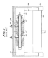
- a molding apparatus used in the transfer molding process is constituted as shown in Fig. 1.
- a cavity 100 is defined between an upper mold unit 101 and a lower mold unit and lower mold units are closed.
- the cavity 100 has an inner peripheral surface for forming a sheath portion and shade portions of a housing of an insulator.
- a heater is provided in or for each of the upper and lower mold units 101 and 102.
- Injection gates 103 are provided in the upper mold unit 101 or the lower mold unit 102 (in this case, the gates 103 are provided in the lower mold units 101).
- a cylinder 104 is located under the lower mold unit 102, and is provided with a press-in piston 105.
- a pot 106 is defined between the piston 105 and the molds 101 and 102 inside the cylinder 104.
- Supports 108 are movable in a direction orthogonal to an axis of the cavity 100 by cylinders 109, and are adapted to support a core 107 in the cavity 100 on one side.
- the core 107 made of an FRP (fiber-reinforced resin) is first set inside the cavity 100 along the axis thereof.
- the core 107 is supported in this state by means of the supports 108.
- a raw rubber composition is charged into the pot 106, and softened there by heating.
- the softened rubber composition is fed into a space between the core 107 and the inner peripheral surface of the cavity 100 through the gates 103 by means of the piston 105.
- the core 107 is pressed by the raw rubber composition.
- the core 107 is supported by the supports 108 on a side opposite to the gates 103, the core is not bent or displaced.
- the rubber composition is heated at a given temperature in the space defined by the inner periphery of the cavity 100 and the outer periphery of the core for a given time after the rubber composition is fully charged. Thereby, the raw rubber composition is vulcanized in this state to form a rubbery housing around the core 107.
- the maximum possible length of the rubbery housing per one molding step is about 2 m considering that a long core 107 will be bent through forced charging of the raw rubber composition inside the cavity even when the supports 108 are provided.
- the length of the housing for the insulator currently used for super high voltage power transmission reaches as much as 5 m or more.
- the supports 108 must be retracted from the inside of the cavity 100 at the final stage of filings the raw rubber-composition inside the cavity under pressure. Therefore, it is a troublesome operation to retract the supports 109. Moreover, since the molding used in the transfer molding process requires the pot, the gate, the supports, etc., the apparatus is complicated, and its production costs rises due to the complexity thereof.
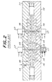
- Japanese patent application Laid-open No. 60-500,929 discloses an injection molding process for the production of the insulator.
- a molding apparatus used in this process is constructed as shown in Fig. 2. That is, a cavity 110 is defined between an upper mold unit 111 and a lower mold unit 112 united together through parting surfaces thereof when the mold units are closed, and an inner periphery of the cavity 110 has a shape constituting a barrel portion and shade portions of an insulator to be molded.
- An injection gate 113 is provided in one of the mold units (the mold unit 111 in this embodiment).
- a protective sleeve 114 is supported by a supports 115 arranged in the upper and lower mold units 111 and 112. The support 115 is movable by a cylinder 117 in a direction orthogonal to an axis of a core 116 placed inside the cavity.
- the core 116 is first arranged inside the cavity 110, and the supports 115 are inwardly moved to press the protective sleeve 114 externally fitted around the core 116 at tips thereof. Thereby, the core 116 is held in the cavity 110 along an axis of the cavity. Next, a raw rubber composition is injected into the cavity around the outer periphery of the core 116 through the gate 113, so that a barrel portion and shelves of a housing are formed around the outer periphery of the core 116.
- the maximum possible length of the obtainable rubbery housing cannot be increased as in the case of the transfer molding process, because the core 116 is bent by the pressure of the rubber composition injected inside the cavity 110.
- Embodiments of the present invention can advantageously provide the following processes and apparatus:-
- the process for producing an insulator by compression molding according to a first aspect of the present invention comprises the steps of:
- the preliminary molding is separately effected from the compression molding and the insulator can be obtained by compression molding the preliminarily molded body, even the insulator having a large length can be integrally produced by using a simpler insulator-molding device.
- an apparatus for producing an insulator according to the first aspect of the present invention which insulator has a core as well as a sheath portion and at least one shade portion around said sheath portion, by compression molding comprising;
- the preliminary molding is separately effected from the compression molding and the insulator can be obtained by compression molding the preliminarily molded body, even the insulator having a large length can be integrally produced by using a simpler insulator-molding device.
- the present inventors have found through further investigations that although the core is positioned in a central portion of the preliminarily molded body by forming the rubber layer around the outer periphery of the core by extrusion, it is not necessarily easy to obtain the insulator in which the core is accurately located as desired in the housing after the compression molding and the curing.
- a second aspect of the present invention is based on the above knowledgement.
- the device for molding a composite insulator according to the second aspect according to the present invention comprises:
- the present inventors have found that although a some excess amount of rubber in the rubber layer of the preliminarily molded body is preferable to assuredly spread the rubber all over the molding cavity, excess rise in pressure inside the cavity is preferably suppressed. That is, according to the third aspect of the present invention, the inner pressure inside the molding cavity of the mold is kept to an appropriate level during the molding.
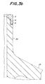
- Figs. 3(a) and 3(b) illustrates one embodiment of the composite insulators to be produced according to the present invention.
- the composite insulator includes a rod-shaped core 1 and a housing 2 integrally and concentrically bonded around the outer periphery of the core 1.
- the core 1 is made of, for example, a fiber-reinforced plastic (FRP), and has a circular sectional shape.
- the housing 2 includes a sheath portion 2a and a plurality of shade portions 2b.
- the sheath portion 2a and the shade portions 2b of the housing 2 are made of, for example, an ethylene-propyrene-diene copolymer rubber (EPDM) or silicon rubber.
- EPDM ethylene-propyrene-diene copolymer rubber
- composite insulators is used herein to mean insulators which are each composed of a core and a housing provided around the outer periphery of the core, the core and the housing being made of different materials.
- the sheath portion 2a and the shade portion 2b are designed to have the following dimensions. That is, as shown in Fig. 10, a radial length "a" of the shade portion is not less than 7 times a thickness "b" of a root portion of the shade portion 2b. The radial length "a” of the shade portion 2b is also not less than 0.7 times a space “p” between the adjacent shade portions 2b. The radial length "a” of the shade portion 2b is generally 50-70 mm, and the thickness "t" of the sheath portion 2a is 3-5 mm, ordinarily 5 mm.
- the producing process of the first aspect of the invention includes a coating step 6, a preliminarily molding step 7, a compression molding step 8 and a finishing step 9.
- the coating step 6 the outer peripheral surface of a core 1 made of an FRP or the like is coated with an adhesive after the core is washed and dried.
- a layer of a raw rubber composition is formed concentrically around the outer periphery of the core.
- the rubber layer may be removed from the preliminarily molded body (See a step 7 in Fig. 4).
- the compressing molding step 8 the preliminarily molded body is compression molded.
- the compression molded body may be cured by heating.
- the finishing step 17 a burr formed around the molded and cured housing is removed.
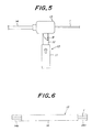
- Fig. 5 shows an extruder 10 to be used in the preliminarily molding step 7.
- the extruder 10 is adapted to extrude the raw rubber composition R around the core 1, and includes an extruding unit 11, a passage 12 for the raw rubber composition R and a cross head 13 through which the rod-shaped core 1 is axially passed.
- a rubber layer 13 is concentrically formed around the outer periphery of the core 1 of FRP.
- a preliminarily molded body 15 obtain in the above preliminarily molding step, while cutting end portions 8a, 8a of the rubber layer 14 is compression molded in the compression molding step 8 by using a molding device 16 as shown in Figs. 4 and 7 (only a mold 17 is shown in these figures).
- the molding device includes an upper mold unit 17a and a lower mold unit 17b.
- the upper and lower mold units 17a and 17b, which constitutes the mold 17 are provided with cavities 18b and 18b of which the inner peripheral surfaces define the outer profile of a housing 2 of an insulator. That is, these cavities 18a and 18b have shapes to form the shapes of the sheath portion 2a and the shade portions 2b.
- the molding apparatus 16 Since a molten raw rubber composition is not poured into cavities 18a and 18b of the upper and lower mold unit 17a and 17b, the molding apparatus 16 requires neither pot nor gate different from the molding apparatus used in the transfer molding apparatus or the injection molding apparatus.
- the molding device 16 is provided with a heater and a pressing unit for tightening the upper and lower molds 17a, 17b for the compression molding.
- the heater or the pressing unit is not shown, because the skilled person would employ such in the compression molding unit.
- the raw rubber composition R is fed into the crosshead 13 through the passage 12 by means of the extruding unit 11 under pressure.
- a vulcanizer such as an organic peroxide or sulfur.
- the core made of FRP or the like, cut in a given length, is fed into the crosshead 13, and the rubber layer 14 is concentrically formed around the outer periphery of the core 1, while being bonded thereto with an adhesive.
- the viscosity (ML 1+4 , 100°C) of the raw rubber composition is preferably set at 15-30, and more preferably at 10-23.
- the raw rubber composition is ordinarily composed mainly of EPDM or silicone rubber, and includes ordinary additives.
- the boundary between the core 1 and the rubber layer 14 is made void-free, which means "free from bubbles".
- the preliminarily molded body 15 formed by the above preliminarily molding step 7 is cut in a given length, and the rubber layer is cut and peeled off at 14a at opposite ends of the core 1 (Step 7 in Fig. 4).
- the volume of the rubber layer 14 of the preliminarily molded body 15 from which the rubber layers 14a have been removed at the opposite ends of the core 1 is set greater than the total volume of the cavities 18a and 18b of the mold 17 so that the rubber composition may be fully spread over the cavities. More specifically, the volume of the rubber layer 14 of the preliminarily molded body 15 as in Fig. 6 is preferably 1.05 to 1.30 times, and ordinarily about 1.15 times the total volume of the cavities 18a and 18b.
- the preliminarily molded body 15 is placed inside a space defined between the upper and lower mold units 17a, 17b, while the mold 17 is opened.
- the mold 17 is heated at a given temperature, and the preliminarily molded body 15 is compression molded into a given shape by closing the upper and lower mold units 17a, 17b relative to each other through operating the pressing means not shown.
- the housing 2 which includes the sheath portion 2a and a plurality of the shade portions 2b is formed around the core 1.
- the rubber of the rubber layer 14 fills the entire cavities 18a and 18b to expel air inside the cavities 18a, 18b.
- a part of the rubber of the rubber layer 14 is pushed out from the cavities 18a and 18b to the parting interface 19 as an excess material, thereby forming a burr projecting from the housing 2.
- the burr 20 is formed around the sheath portion 2a and the shade portions 2b at the parting interface 19. Since the core 1 is uniformly pressed in all directions by the upper and lower molds 17a and 17b during the molding, the core 1 is not bent. This enables use of long cores 1.
- the heating temperature i.e. the vulcanizing temperature in the molding step is ordinarily set at 150-180°C, and the heating time is around 10 minutes. Since the adhesive is present around the outer peripheral surface of the core 1 a boundary layer having high electric insulation is formed between the sheath portion 2a and the core 1 through the vulcanization and bonding. The crosslinked structure is formed in the rubber through the action of the vulcanizing agent inside the rubber layer by heating under pressure. Consequently, elasticity is imparted upon the rubber, and firmly adhering forces are developed between the rubber and the core 1.
- the burr of the housing 2 is removed, thereby obtaining a finished product.
- the burr formed at edge portions of the outer periphery of the shed portions 2b is easily removed by using scissors or a knife, and the remaining burr at the other portion is removed by hand.
- the housing having a length of not less than 5 m can be molded integrally with the core from the preliminarily molded body by using the compression molding apparatus with the mold having a large length without any special difficulty. Therefore, different from a case where short housings are joined together, since no seam exists in the long housing 2, reduction in insulating property of the housing 2 is not feared. In addition, since the molding device does not need a pot, a gate or supports, the construction thereof is simple.
- the sectional shape of the preliminarily molded body 15 may be elliptical (as shown in Fig. 11) or rhombic (as shown in Fig. 12).
- the ratio of a minor axis to a major axis in the elliptical shape and the ratio of a longer diagonal to a shorter diagonal in the rhombic section are preferably set at not more than 1:3.
- the cavities 11 and 12 are preferably designed such that the major axis (Fig. 11) or the longer diagonal (Fig. 12) is located at the position of the parting interface 19 of the mold.
- each mold unit may be constituted by a plurality of molding segments 17a 1 , 17a 2 , 17a 3 , ⁇ 17a n ; 17b 1 , 17b 2 , 17b 3 ⁇ 17b n ) piled and tightened one upon another through long bolts 22 passed through respective holes formed in the molding segments. Nuts 23 are screwed to the bolt 22 at opposite ends thereof to firmly tighten the molding segments. These segments have substantially same configuration, excluding those at the opposite ends of the mold. A shade portion is to be formed between adjacent molding segments of the upper and lower mold units. In this embodiment, the length of the housing can be arbitrarily changed by changing the number of the molding segments piled one upon another for each of the mold units.
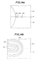
- Figs. 14(a) and 14(b) illustrate another embodiment of the compression mold in which two rows of V-grooves 24a, 24b are formed at parting faces 19a i , 19b i of molding segments 17a i , 17b i along the cavity 18a i , 18b i in each of the upper and lower molds 17a, 17b.
- Fig. 14(a) is a side view of upper and lower molding segments 17a i , 17b i butted together
- Fig. 14(b) is a plane view of lower molding segments 17b 1 , 17b i +1 piled one upon another.
- This embodiment is similarly applicable to the upper molding unit and the lower molding unit each of which is of an integral type as shown in Fig. 7.
- the burr can be easily removed.
- the inner edge of the inner V-groove 24a is formed by an edge of each of the cavities 18a i , 18b i as shown in Figs. 14(a) and 14(b) by a dotted line, the burr can be more easily and clearly removed.
- Figs. 15(a) and 15(b) illustrate another embodiment of the first aspect of the producing process of the invention in which a pair of strips 25 of the raw rubber composition R are placed on the lower mold unit 17b on opposite sides of the preliminarily molded body 15.
- This embodiment has been contrived based on the following knowledge. That is, if the diameter of the shade portions is small, the preliminarily molded body 15 having the volume of the rubber being around 1.1 times the total volume of the cavities 18a, 18b of the upper and lower mold units 17a, 17b can be molded to give an excellent insulator with a housing.
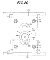
- Figs. 16(a) and 16(b) illustrates an embodiment of the second aspect of the present invention. More specifically, Fig. 16(a) illustrate as mold 17 for the production of an insulator similar to that in Fig. 13.
- the mold 17 is constituted by an upper mold unit 17a as a movable mold and a lower mold unit 17b as a stationary mold unit.
- Each of the upper and lower mold units 17a, 17b is constituted by a plurality of molding segments (17a 1 , 17a 2 , 17a 3 , ⁇ 17a n ; 17b 1 , 17b 2 , 17b 3 , ⁇ 17b n ) having the same shape, excluding 17a 1 , 17a n , 17b 1 , 17b n .
- These segments 17a 1 , 17a n , 17b 1 and 17b n have almost the same shape.
- These molding segments of each of the upper and lower mold units are tightened by passing long bolts 22 through holes bored in the segments on opposite sides thereof and screwing nuts 23 to threads 26 formed around the bolts at end portions of the mold.
- the length of the mold may be varied by changing the number of the segments 17a 1 , ⁇ 17a n ; 17b 1 , ⁇ 17b n of each of the upper and lower mold units 17a, 17b.
- a locating member shown in Fig. 16(b) is fitted to the molding segments (17a 1 , 17a 2 ; 17b 1 , 17b 2 ; 17a n-1 , 17a n ; 17b n-1 , 17b n at each of opposite ends of the mold 17 by utilizing a molding cavity sections 18a 1 , 18b 1 ; 18a n-1 , 18b n-1 defined between the adjacent molding segments (17a 1 , 17a 2 ; 17b 1 , 17b 2 ; 17a n-1 , 17a n ; 17b n-1 , 17b n ).
- the locating member 27 is designed in the form of an end cap as the locating means, and includes a guide portion 27 having a larger diameter. Faces 28a and 28b on the opposite side of the guide portion 28 are inclined corresponding to the inclined faces 18a 1-1 , 18a 1-2 , 18b 1-1 , 18b 1-2 of the cavity section 18 at the same angles. Behind the guide portion 28 is provided a small diameter portion 29. A gripping hole 30 is bored in a central portion of the guide portion 28 and the small diameter portion 29 of the end cap 27. A threaded hole 31, which has a larger diameter than that of the gripping hole 30, is bored in the small diameter portion 29 on a side opposite to the guide portion 28.
- a smaller diameter threaded portion 32 is screwed a smaller diameter threaded portion 32a of an end portion 32 having the same diameter as that of the small diameter portion 29, while a shim 33 is interposed between the bottom the threaded hole 31 and the threaded portion 32a.
- the shim is pressed against the bottom of the threaded hole 31 by means of a screw bolt 34 screwed to threads formed around a central hole bored through the end portion 32.
- Larger holes 18a 0 , 18b 0 are formed in a central portion of the molding segments 17a 1 , 17b 1 , 17a n , 17b n and the portions 29 and 32 of the end cap are intimately fitted into such large holes.
- the preliminarily molded body is set between the upper mold unit 17a and the lower mold unit 17b in the state that the end cap 27 is fitted around each of the opposite ends of the core 1.
- a screw hole 45 is formed in the end cap on a side opposite to the guide 41.
- the screw hole 45 continues to the gripping hole 44.
- a cap 46 is screwed to the screw hole 45 through a shim 47 held between the tip of the cap 46 and the bottom face of the screw hole.
- the shim 47 receives the end of the core 1. That is, the shim is made of a material such as a fluorine resin so that when the core is expanded and butted to the shim under heating the insulator, the shim may receive the end of the core 1 to prevent damage upon the end of the core 1.
- the core 1 can be located at an appropriate location inside the housing 2 of the insulator by butting the locating faces 28a, 28b (inclined faces) of the locating members 27 against those (18a 1-1 , 18a 1-2 , 18b 1-1 , 18b 1-2 , ⁇ ) of the adjacent molding segments (cavity sections) at the opposite ends of the mold 17.
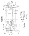
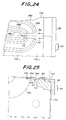
- Fig. 17 through Fig. 19 illustrate another embodiment of the second aspect of the present invention.
- the same or similar reference numerals as in Figs. 16(a) and 16(b) are given to same or similar constituent parts as in Figs. 16(a) and 16(b).
- the upper mold unit 17a is constituted by molding segments 17a 1 , ⁇ 17a n piled and tightened one upon another, whereas the lower mold unit 17b is constituted by molding segments 17b 1 , ⁇ 17b n .
- the adjacent segments 17a 1 , 17a 2 ; 17a n-1 , ⁇ 17a n of the upper mold unit 17a and the adjacent segments 17b 1 , 17b 2 ; 17b n-1 , 17b n of the lower mold unit 17b which are all located at the opposite end portions of the mold.
- the other remaining intermediate molding segments 17a 3 , ⁇ 17a n-2 , and 17b 3 , ⁇ 17b n-2 all have substantially the same shape.
- the housing is formed inside the molding cavity around the outer periphery of the core 1.
- a semi-circular receiving section 35a, 35b is formed in a side face of each of the upper molding segment 17a 1 , 17a n and the lower molding segment 17b 1 , 17b n on each of the opposite ends of the mold.
- a semi-circular receiving section 36a, 36b is formed in a side face of each of the upper molding segment 17a 2 , 17a n-1 and the lower molding segment 17b 2 , 17b n-1 adjacent to the upper and lower molding segments 17a 1 , 17a n , 17b 1 , 17b n , respectively, while being opposed to the receiving sections 35a, 35b.
- a semi-circular recess 37a, 37b is formed in a central portion of each of the upper molding segment 17a 1 and the lower molding segment 17b 1 , and communicate the receiving sections 35a, 35b.
- Inclined surfaces 38a and 38b are formed at bottoms of the receiving sections 35a and 35b as viewed in the axial direction of the mold, respectively.
- Inclined surfaces 39a, 39b are formed at bottoms of the receiving sections 36a, 36b, respectively.
- the surfaces 38a, 38b are inclined axially inwardly in a radially outward direction, while the surfaces 39a, 39b are inclined axially outwardly in the radially outward direction.
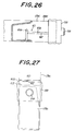
- a hole 28 is defined between the lower molding segments 17b 1 and 17b 2 as shown in Fig. 17, and an ejector pin 41 is movably fitted in the hole 28.
- an end cap 42 is fitted, as a locating member or means, to each of opposite ends of the core 1.
- the end cap 42 functions to locate the core at an appropriate location inside the mold during the compression molding.
- the end cap has such an outer configuration as capable of being received in the receiving sections 35a, 35b, 36a, 36b and the recessed portion 37a, 37b.
- the end cap 40 has circular section, and includes a guide 43 having an outer diameter greater than that of the remainder. Opposite surfaces 43a and 43b of the guide 41 are so inclined that the inclined surfaces 43a and 43b are intimately fit to those 38a, 38b and 39a, 39b of the molding segments 17a 1 , 17a 2 , 17b 1 , 17b 2 ,. That is, the surface 43a is inclined axially inwardly in a radially outward direction, while the surface 43b is inclined axially outwardly in the radially outward direction.
- a gripping hole 44 is bored in a central portion of the end cap 42. The preliminarily molded body is set between the upper and lower mold units in the state that the cap end 42 is fitted to the core at each of the opposite ends such that the end portion of the core is inserted into the gripping hole.
- a larger diameter portion 45 is formed in the gripping hole 44 on a core-inserting side.
- This larger diameter portion 45 is to form an end portion of the housing 2.
- An annular groove 46 is formed on the inclined surface 43b of the guide 43 near the larger diameter portion 45. This annular groove 46 is to form a projection as shown at 5 in Fig. 3(b).
- Annular groove 47 is formed on the inner peripheral surface of the larger diameter portion 45, and is to form a projection as shown at 4 in Fig. 3(b).
- an annular groove 48 is formed around the inner peripheral surface of the gripping hole 44 axially inside the annular groove 47. The groove 48 functions to catch the rubber leaking from the larger diameter portion 45 and to prevent the rubber from flowing axially outwards the groove 48 during molding the housing 2.
- a threaded hole 49, an end portion 50, a small diameter portion 50a, a shim 51 and a screw bolt 52 have the same construction as that in Fig. 16.
- a preliminarily molding step is carried out, in which an extruder 10 shown in Fig. 5 is used.
- a preliminarily molded body is obtained from a raw rubber material R as mentioned before in connection with Figs. 5 and 6.
- a coating step is carried out similarly as described in connection with Fig. 4 before the preliminarily molding step.
- the end cap 40 is fitted as the locating member at each of the end portions of the core 1 of the preliminarily molded body 15.
- the preliminarily molded body 15 is set on the lower mold unit 17b as the stationary mold unit in the state that the upper mold unit 17a as a movable molded unit is opened relative to the lower mold unit 17b. Since the outer diameter of the rubber layer 14 of the preliminarily molded body 15 is greater than that of the diameter of the molding face 22 to constitute the sheath portion, each of the end caps 42 is floated without being received in the receiving sections 35a, 36a and 35b, 36b.
- the upper and lower mold units 17a and 17b are heated to a given temperature by an appropriate heater not shown, and the upper mold unit 17a is lowered to close the mold 17. At that time, even if the preliminarily molded body 15 is slightly positionally deviated from the core 1, the inclined faces 43a and 43b of the guide 43 contact those 38a, 38b, 39a, 39b of the receiving sections 35a, 35b, 36a, 36b, as the upper mold unit 17a is closed to the lower mold unit 17b. Thereby, the core 1 is located in a given central location of the molding face 22 by the guiding action of the inclined faces.
- the rubber layer 14 of the preliminarily molded body 15 is compression molded into a given shape by the molding face 22 constituted by the mold units 17a and 17b when the upper mold unit 17a is closed to the inner mold 17b. Since the volume of the rubber layer 14 of the preliminarily molded body 15 is greater than that of the molding cavity defined by the molding face 22, the rubber of the rubber layer 14 fills the enter cavity defined by the molding face 22 when the rubber layer 14 is compression molded between the upper and lower mold units 17a and 17b to expel air inside the cavity and form the sheath portion 2a and the shade portions 2b.
- an end portion of the sheath 2a is formed by the larger diameter portion 48 of the end cap 44, and the projections 4 and 5 (Fig. 3b) are formed by the annular grooves 45 and 46, respectively.
- the heating temperature i.e., the vulcanizing temperature on molding is ordinarily set at 150-180°C, and the heating time is ordinarily set at around 10 minutes. Between the sheath 2a and the core 1 is formed a boundary having electrically high reliability through bonding under vulcanization.
- the mold unit 17a is raised from the lower mold unit 17b to open the mold, and the ejector pin 41 inside the receiving hole 40 defined between the lower molding segments 17b 1 and 17b 2 is lifted to push up the end cap 42.
- the molded insulator is released from the mold.
- the end caps are removed from the cores 1, and a burr and the rubber caught in the groove 48 are finally removed.
- the burr can be easily removed by scissors or a knife.
- the annular groove 48 is so designed as to enable the rubber caught therein to be removed by hand without using scissors. Since no adhesive is coated on a portion of the core corresponding to the groove 48, the rubber can be easily removed by hand.
- the core can be aligned with the center of the molding face 22 on molding even if the core is slightly positionally deviated from the center of the preliminarily molded body 15. Therefore, it is not feared that the core 1 is broken between the mold units 17a and 27b of the mold 17. Therefore, the yield for the products can be enhanced.
- the housing 2 is formed by compression molding, it is unnecessary to pour rubber into the molding face 22. Therefore, a pot, a gate unit, etc. required by the conventional transfer molding process are omitted, which simplifies the construction of the insulator-molding device.
- the core is not bent.
- the long insulator housing which may be used for transmission of high voltage electric power, can be integrally and easily produced.
- the core 1 is not bent, supports as required in the transfer molding process are unnecessary, which also simplifies the construction of the molding device.
- the countermeasure or countermeasures illustrated in connection with Figs. 14(a) and 14(b) and/or Figs. 15(a) and 15(b) may be employed so long as such will not damage the merit obtained by this second aspect of the invention.
- Excess rubber coming out into a clearance between the parting faces 19a and 19b on molding is caught by the grooves 24a and 24b.
- a burr formed around a housing 2 can be easily removed by grasping rigid rubber portions formed within these grooves.
- a rubber-escaping groove is formed at a parting face of at least one of the stationary mold unit and the movable mold unit of the mold between the molding face of the cavity of the mold and the outer periphery of the mold.
- the rubber-escaping groove preferably includes at least two grooves in which the groove located outwardly is deeper than that located inwardly of the mold.
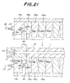
- a portion of the molding face 22 and the outer side of the mold are formed three grooves, that is an innermost groove 53, an intermediate groove 54, and an outermost groove 55 of which depths are increased in this order.
- the innermost groove 53 is opened to the pressing face 22, and the outermost groove 55 is opened to the outer side of the mold.
- An exchangeable key 56 is fitted in the intermediate groove 54, and is pressed against a vertical wall 57 between the grooves 53 and 54 by means of an end portion of an angular pressing plate 58 fitted in the groove 55, while the other end portion is in turn fixed to the lower molding segment by a cap bolt 59.
- the key is prevented from slipping out from the groove 54 by the pressing plate 58 and the cap bolt 59.
- the pressing plate 58 may be commonly used for any one of the lower molding segment 17b 1 , ⁇ 17b n , and fixed to the outer side faces thereof by means of the end bolts 59.
- a gap 80 is defined as a rubber-escaping groove between the upper face of the key 56 and the parting face 19a of the upper molding segment 17a i including the groove 53 and a gap between the angular plate 58 and the parting face 19. This gap 80 may be adjusted by selectively using an appropriate key 56 having a given thickness.
- the rubber inside the gap 80 is vulcanized more earlier by heating than in the cavity inside the molding face 22, because the interior of the gap is far smaller than the cavity. Therefore, the gap 80 is closed with cured rubber at an early stage, so that the cavity inside the molding space is sealed. Consequently, the pressure in the cavity inside the molding face can be kept at an appropriate level.
- the housing can be formed, accurately following the shape of the molding face 22.
- the rubber-escaping groove is opened at the outermost side portion of the molding face 22 where the raw material is most difficult to reach, the rubber composition is smoothly and assuredly led to the outermost side of the molding face 22 and then to the rubber-escaping groove. Therefore, the housing 2 can be prevented therefrom being drawn in a depressed form, so that cracking is prevented from occurring at a bottom portion of the drawn portion of the housing. The rubber flown out to the gap 80 is cut off after the housing 2 is formed.
- a rubber-escaping groove 61 is formed in a bent shape at a parting face 19b i of a low molding segment 17b i such that an inner end of the rubber-escaping groove 61 is opened to the molding face 22 corresponding to a rear surface of a shade portion and an outer end thereof is opened outside the molding segment 17b i .
- the rubber-escaping element includes an inner groove 61a and an outer groove 61b.
- the inner groove 61a is opened to the molding face 22, and extends in an axial direction of the mold unit 17.
- the outer groove 61b is joined to the inner groove 61a at right angles, and opened outside the molding segment 17b i .
- the grooves 61a and 61b have almost the same depth in this embodiment but may have different depths.
- a key 62 is detachably fitted into the outer groove 61b, and a gap 60 is formed as a rubber-escaping groove between the upper face of the key 62 and the parting face 19a i of the upper molding segment 19a i , including the inner groove 61a.
- An appropriate key 62 may be selectively used depending upon the height of the gap 60 desired.
- An angular plate 58 and a cap bolt 59 are used for the same purpose as in the embodiment of Figs. 22-24.
- a depression 63 is formed to receive an end portion of the angular plate 58.
- a V-shaped groove 24a is formed at a parting face 19b i of the lower molding segment 17b i along the outer contour of the molding face 22.
- a part of excess rubber expanded by heating escapes outside from the molding face 22 up to the gap 60 through the inner groove 61a. Therefore, the pressure inside a cavity within the molding face 22 can be kept at an appropriate level so that a housing having a shape accurately in conformity with the molding face 22 can be molded. Furthermore, the rubber can be prevented from being drawn at locations corresponding to the parting faces 19a i and 19b i at the shade portion 2b. In addition, since the escaping groove 60 is continued to the rear face of the shade portion 2b, a trace of the escaping groove 60 may be retained at the rear face of the shade portion only to make the appearance of the insulator good.
- the present invention hereinbefore explained can be widely applied to the composite insulators, also called “polymer insulators", having the structure in which a housing made of an electrically insulating material such as EPDM rubber is provided around the outer periphery of a rod-shaped insulating supporting member made of, for example, a fiber-reinforced plastics.
- a housing made of an electrically insulating material such as EPDM rubber is provided around the outer periphery of a rod-shaped insulating supporting member made of, for example, a fiber-reinforced plastics.
Applications Claiming Priority (7)
| Application Number | Priority Date | Filing Date | Title |
|---|---|---|---|
| JP68280/93 | 1993-03-26 | ||
| JP5068280A JPH0815025B2 (ja) | 1993-03-26 | 1993-03-26 | ノンセラミック碍子の成形装置 |
| JP6828093 | 1993-03-26 | ||
| JP73926/93 | 1993-03-31 | ||
| JP7392693 | 1993-03-31 | ||
| JP7392693A JP2607820B2 (ja) | 1993-03-31 | 1993-03-31 | 碍子の成形金型及び成形方法 |
| EP94302075A EP0624446B1 (fr) | 1993-03-26 | 1994-03-23 | Procédé et appareil pour la fabrication d'isolateurs |
Related Parent Applications (1)
| Application Number | Title | Priority Date | Filing Date |
|---|---|---|---|
| EP94302075A Division EP0624446B1 (fr) | 1993-03-26 | 1994-03-23 | Procédé et appareil pour la fabrication d'isolateurs |
Publications (2)
| Publication Number | Publication Date |
|---|---|
| EP0873838A2 true EP0873838A2 (fr) | 1998-10-28 |
| EP0873838A3 EP0873838A3 (fr) | 2000-04-19 |
Family
ID=26409494
Family Applications (2)
| Application Number | Title | Priority Date | Filing Date |
|---|---|---|---|
| EP98111847A Ceased EP0873838A3 (fr) | 1993-03-26 | 1994-03-23 | Procédé et appareil pour la fabrication d'insolateurs |
| EP94302075A Expired - Lifetime EP0624446B1 (fr) | 1993-03-26 | 1994-03-23 | Procédé et appareil pour la fabrication d'isolateurs |
Family Applications After (1)
| Application Number | Title | Priority Date | Filing Date |
|---|---|---|---|
| EP94302075A Expired - Lifetime EP0624446B1 (fr) | 1993-03-26 | 1994-03-23 | Procédé et appareil pour la fabrication d'isolateurs |
Country Status (6)
| Country | Link |
|---|---|
| US (1) | US5523038A (fr) |
| EP (2) | EP0873838A3 (fr) |
| CN (1) | CN1056797C (fr) |
| AU (1) | AU662856B2 (fr) |
| CA (1) | CA2119694C (fr) |
| DE (1) | DE69415715T2 (fr) |
Cited By (2)
| Publication number | Priority date | Publication date | Assignee | Title |
|---|---|---|---|---|
| EP1260337A1 (fr) * | 2001-05-22 | 2002-11-27 | Ngk Insulators, Ltd. | Appareil pour peler du matériau d'extrusion |
| CN113171955A (zh) * | 2021-03-17 | 2021-07-27 | 平高集团有限公司 | 一种盆式绝缘子表面涂覆涂层固化装置 |
Families Citing this family (33)
| Publication number | Priority date | Publication date | Assignee | Title |
|---|---|---|---|---|
| JPH08185737A (ja) * | 1994-12-28 | 1996-07-16 | Ngk Insulators Ltd | 複合碍子およびその製造に用いるセグメントさらにそれを用いた複合碍子の製造方法 |
| JP2971774B2 (ja) * | 1995-03-20 | 1999-11-08 | 日本碍子株式会社 | 高分子材料成形型の離型治具 |
| JP2905416B2 (ja) * | 1995-03-20 | 1999-06-14 | 日本碍子株式会社 | 複合碍子の端部分成形方法およびそれに用いる端部分成形治具 |
| JP2804451B2 (ja) * | 1995-03-23 | 1998-09-24 | 日本碍子株式会社 | 複合碍子製造用圧縮成形金型 |
| FR2739720B1 (fr) * | 1995-10-04 | 1997-12-05 | Schneider Electric Sa | Procede de fabrication d'un isolateur et isolateur realise selon ce procede |
| US5822857A (en) * | 1996-03-18 | 1998-10-20 | Ngk Insulators, Ltd. | Method of repairing shed portion of composite insulator |
| JP2938801B2 (ja) * | 1996-03-18 | 1999-08-25 | 日本碍子株式会社 | 複合碍子の製造方法および金型へのコアロッドの保持リング |
| JP3157756B2 (ja) * | 1997-10-13 | 2001-04-16 | 日本碍子株式会社 | ポリマー碍子の成形方法 |
| JP2923276B2 (ja) * | 1998-01-08 | 1999-07-26 | 日本碍子株式会社 | 成形用金型およびその取り扱い方法 |
| US6306331B1 (en) | 1999-03-24 | 2001-10-23 | International Business Machines Corporation | Ultra mold for encapsulating very thin packages |
| US6171091B1 (en) * | 1999-05-12 | 2001-01-09 | Callaway Golf Company | Replaceable mold cavities and mold cavity inserts |
| DE19944513C1 (de) * | 1999-09-16 | 2001-01-25 | Sefag Ag Malters | Verfahren zur Herstellung eines Hochspannungsisolators, Hochspannungsisolator sowie Vorrichtung zur Durchführung eines solchen Verfahrens |
| US6831232B2 (en) * | 2002-06-16 | 2004-12-14 | Scott Henricks | Composite insulator |
| US6952154B2 (en) | 2002-06-16 | 2005-10-04 | Maclean-Fogg Company | Composite insulator for fuse cutout |
| US20070102098A1 (en) * | 2005-11-09 | 2007-05-10 | Wang Swei M | Method for making shell for electric product |
| CN101609738B (zh) * | 2009-07-21 | 2012-08-22 | 国网电力科学研究院武汉南瑞有限责任公司 | 用于高压电缆附件绝缘部分制造的成型模具 |
| CN102069542A (zh) * | 2010-11-04 | 2011-05-25 | 中国西电电气股份有限公司 | 一种绝缘筒浇注模具 |
| CN102118010B (zh) * | 2010-12-10 | 2013-08-28 | 上海永锦电气集团有限公司 | 硅橡胶电缆终端生产模具 |
| US9731464B2 (en) | 2011-08-10 | 2017-08-15 | Nike, Inc. | Article of footwear formed from two preforms and method and mold for manufacturing same |
| US9096028B2 (en) * | 2011-08-10 | 2015-08-04 | Nike, Inc. | Article of footwear formed from two preforms and method and mold for manufacturing same |
| CN107263799B (zh) | 2011-08-30 | 2019-12-03 | 上海延锋金桥汽车饰件系统有限公司 | 一种在模具中制造车辆内饰组件的方法以及用于车辆内部的饰件 |
| US10464280B2 (en) | 2011-08-30 | 2019-11-05 | Shanghai Yanfeng Jinqiao Automotive Trim Systems Co. Ltd. | Trim component for vehicle interior |
| CN103065745A (zh) * | 2011-10-20 | 2013-04-24 | 襄樊国网合成绝缘子股份有限公司 | 一种模压绝缘子制作方法 |
| CN102601894B (zh) * | 2012-03-06 | 2014-10-15 | 安徽奥丰汽车配件有限公司 | 汽车防尘套类成型模具 |
| US10093268B2 (en) | 2012-08-27 | 2018-10-09 | Shanghai Yanfeng Jinqiao Automotive Trim Systems Co. Ltd. | Trim component for vehicle interior |
| CN103434059A (zh) * | 2013-06-27 | 2013-12-11 | 国家电网公司 | 一种高压直流输电设备用绝缘套生产模具 |
| CN105023642B (zh) * | 2015-07-28 | 2017-01-04 | 远东电缆有限公司 | 一种智慧能源动车组用低烟无卤阻燃高压软电缆及生产工艺 |
| CN105563712A (zh) * | 2016-01-04 | 2016-05-11 | 江苏沙洲电气有限公司 | 一种线夹绝缘罩的生产工艺 |
| CN106217722A (zh) * | 2016-08-04 | 2016-12-14 | 江门市鲁班尼光电科技有限公司 | 一种户外线上防水驱动模块的制作方法 |
| EP3814176B1 (fr) | 2018-06-28 | 2024-02-21 | Shanghai Yanfeng Jinqiao Automotive Trim Systems Co. Ltd | Composant de garniture de véhicule |
| US11623416B2 (en) * | 2019-06-19 | 2023-04-11 | Arris Composites Inc. | Multi-part molds and methods for forming complex fiber-composite parts |
| CN112590093B (zh) * | 2020-11-25 | 2022-06-17 | 贵州红阳机械有限责任公司 | 一种端盖零件压制工艺的模具及应用 |
| CN112863787B (zh) * | 2021-01-09 | 2022-10-28 | 国网上海市电力公司 | 一种电力绝缘子制造成型工艺 |
Citations (6)
| Publication number | Priority date | Publication date | Assignee | Title |
|---|---|---|---|---|
| US2435567A (en) * | 1944-10-18 | 1948-02-10 | Columbia Protektosite Company | Method and apparatus for molding wire core temples |
| FR1567954A (fr) * | 1967-03-11 | 1969-05-23 | ||
| US4312123A (en) * | 1979-03-12 | 1982-01-26 | Interpace Corporation | Methods of making high voltage electrical insulators and oil-less bushings |
| US4501715A (en) * | 1983-05-18 | 1985-02-26 | Gilbert Barfield | Mold and method for forming golf balls |
| FR2576655A1 (fr) * | 1985-01-25 | 1986-08-01 | Alsthom Atlantique | Hauban isolant |
| JPH05182546A (ja) * | 1992-01-08 | 1993-07-23 | Ngk Insulators Ltd | 碍子の製造方法 |
Family Cites Families (9)
| Publication number | Priority date | Publication date | Assignee | Title |
|---|---|---|---|---|
| FR2505915A1 (fr) * | 1981-05-12 | 1982-11-19 | Ceraver | Procede de fabrication d'un isolateur de hauban de type composite |
| FR2523361A1 (fr) * | 1982-03-15 | 1983-09-16 | Ceraver | Procede de fabrication d'un revetement isolant a profil cannele sur un support cylindrique, et dispositif de mise en oeuvre du procede |
| SU1030862A1 (ru) * | 1982-04-22 | 1983-07-23 | Ленинградский Ордена Ленина Политехнический Институт Им.М.И.Калинина | Способ нанесени ребристого покрыти на длинномерные издели |
| FR2543356B1 (fr) * | 1983-03-25 | 1986-01-10 | Ceraver | Procede et dispositif de moulage du revetement isolant d'un isolateur organique de grande longueur |
| GB8312892D0 (en) * | 1983-05-11 | 1983-06-15 | Raychem Ltd | Electrical insulator |
| US4724284A (en) * | 1986-01-27 | 1988-02-09 | Lapp Insulator Company | High voltage composite insulator and method of making same |
| FR2596569B1 (fr) * | 1986-03-25 | 1988-05-20 | Ceraver | Dispositif de demoulage d'un isolateur electrique composite |
| US5233132A (en) * | 1986-10-02 | 1993-08-03 | Sediver Societe Europeenne D'isolateurs En | Composite insulator comprising a fiber-resin rod and an insulating coating molded thereover |
| JPH0780207B2 (ja) * | 1992-01-23 | 1995-08-30 | 日本碍子株式会社 | ノンセラミック碍子の製造方法及び製造装置 |
-
1994
- 1994-03-16 US US08/213,801 patent/US5523038A/en not_active Expired - Fee Related
- 1994-03-23 DE DE69415715T patent/DE69415715T2/de not_active Expired - Fee Related
- 1994-03-23 EP EP98111847A patent/EP0873838A3/fr not_active Ceased
- 1994-03-23 EP EP94302075A patent/EP0624446B1/fr not_active Expired - Lifetime
- 1994-03-23 CA CA002119694A patent/CA2119694C/fr not_active Expired - Fee Related
- 1994-03-24 AU AU59009/94A patent/AU662856B2/en not_active Ceased
- 1994-03-25 CN CN94103356A patent/CN1056797C/zh not_active Expired - Fee Related
Patent Citations (6)
| Publication number | Priority date | Publication date | Assignee | Title |
|---|---|---|---|---|
| US2435567A (en) * | 1944-10-18 | 1948-02-10 | Columbia Protektosite Company | Method and apparatus for molding wire core temples |
| FR1567954A (fr) * | 1967-03-11 | 1969-05-23 | ||
| US4312123A (en) * | 1979-03-12 | 1982-01-26 | Interpace Corporation | Methods of making high voltage electrical insulators and oil-less bushings |
| US4501715A (en) * | 1983-05-18 | 1985-02-26 | Gilbert Barfield | Mold and method for forming golf balls |
| FR2576655A1 (fr) * | 1985-01-25 | 1986-08-01 | Alsthom Atlantique | Hauban isolant |
| JPH05182546A (ja) * | 1992-01-08 | 1993-07-23 | Ngk Insulators Ltd | 碍子の製造方法 |
Non-Patent Citations (1)
| Title |
|---|
| PATENT ABSTRACTS OF JAPAN vol. 017, no. 593 (E-1454), 28 October 1993 (1993-10-28) & JP 05 182546 A (NGK INSULATORS LTD), 23 July 1993 (1993-07-23) * |
Cited By (3)
| Publication number | Priority date | Publication date | Assignee | Title |
|---|---|---|---|---|
| EP1260337A1 (fr) * | 2001-05-22 | 2002-11-27 | Ngk Insulators, Ltd. | Appareil pour peler du matériau d'extrusion |
| CN113171955A (zh) * | 2021-03-17 | 2021-07-27 | 平高集团有限公司 | 一种盆式绝缘子表面涂覆涂层固化装置 |
| CN113171955B (zh) * | 2021-03-17 | 2022-09-30 | 平高集团有限公司 | 一种盆式绝缘子表面涂覆涂层固化装置 |
Also Published As
| Publication number | Publication date |
|---|---|
| US5523038A (en) | 1996-06-04 |
| CA2119694A1 (fr) | 1994-09-27 |
| CA2119694C (fr) | 1997-11-11 |
| AU5900994A (en) | 1994-10-20 |
| AU662856B2 (en) | 1995-09-14 |
| DE69415715T2 (de) | 1999-06-10 |
| EP0624446A1 (fr) | 1994-11-17 |
| DE69415715D1 (de) | 1999-02-18 |
| EP0624446B1 (fr) | 1999-01-07 |
| CN1056797C (zh) | 2000-09-27 |
| CN1094672A (zh) | 1994-11-09 |
| EP0873838A3 (fr) | 2000-04-19 |
Similar Documents
| Publication | Publication Date | Title |
|---|---|---|
| US5523038A (en) | Process and an apparatus for producing insulators | |
| US5612069A (en) | Apparatus for manufacturing a long non-ceramic insulator in a mold longitudinally shorter than the insulator | |
| US3825457A (en) | Method of mouldig hollow rubber articles | |
| US5811049A (en) | Method for producing composite insulator | |
| JP2824025B2 (ja) | 複合碍子およびその製造方法 | |
| JPH0815022B2 (ja) | 碍子の製造方法 | |
| US3898121A (en) | Apparatus for molding hollow rubber articles | |
| US3879517A (en) | Method for making a dual seal insulator for multiple conductor connectors | |
| KR100615814B1 (ko) | 고분자 애자 제조방법 | |
| CN113119392A (zh) | 分流挤包电缆绝缘连接方法 | |
| US3930771A (en) | Apparatus for manufacturing a dual seal insulator | |
| CN210190380U (zh) | 一种硫化和注塑同步完成的线缆模具 | |
| JP2849349B2 (ja) | 電気融着継手とその製造方法及びその射出成形用金型 | |
| CN114454423A (zh) | 一种焊接式整体注塑多通道电缆治具及其使用方法 | |
| JPS61143112A (ja) | 合成樹脂の固相押出成形方法 | |
| JP3012515B2 (ja) | Cvケーブルの絶縁接続方法 | |
| CN216014934U (zh) | 一种高压电缆动力线接头处修补胶套 | |
| CN220946356U (en) | Mold structure for long copper bar encapsulation injection molding | |
| CN210791835U (zh) | 一种新型绳锯注胶模具 | |
| CN218615213U (zh) | 汽车车灯反射碗的注塑模具 | |
| CN212764370U (zh) | 精密电机用电线固定防漏护套硫化模 | |
| CN212666607U (zh) | 用于塑胶成型模具的脱模机构 | |
| KR910003329B1 (ko) | 고전압 케이블 접속용 스트레스 콘(stress cone)의 성형장치 | |
| JPH0780207B2 (ja) | ノンセラミック碍子の製造方法及び製造装置 | |
| CA2151351A1 (fr) | Appareil et procede de production de pieces moulees |
Legal Events
| Date | Code | Title | Description |
|---|---|---|---|
| PUAI | Public reference made under article 153(3) epc to a published international application that has entered the european phase |
Free format text: ORIGINAL CODE: 0009012 |
|
| AC | Divisional application: reference to earlier application |
Ref document number: 624446 Country of ref document: EP |
|
| AK | Designated contracting states |
Kind code of ref document: A2 Designated state(s): DE FR GB |
|
| PUAL | Search report despatched |
Free format text: ORIGINAL CODE: 0009013 |
|
| AK | Designated contracting states |
Kind code of ref document: A3 Designated state(s): DE FR GB |
|
| 17P | Request for examination filed |
Effective date: 20000615 |
|
| 17Q | First examination report despatched |
Effective date: 20010820 |
|
| GRAG | Despatch of communication of intention to grant |
Free format text: ORIGINAL CODE: EPIDOS AGRA |
|
| STAA | Information on the status of an ep patent application or granted ep patent |
Free format text: STATUS: THE APPLICATION HAS BEEN REFUSED |
|
| 18R | Application refused |
Effective date: 20020728 |