EP0873838A2 - A process and an apparatus for producing insulators - Google Patents
A process and an apparatus for producing insulators Download PDFInfo
- Publication number
- EP0873838A2 EP0873838A2 EP98111847A EP98111847A EP0873838A2 EP 0873838 A2 EP0873838 A2 EP 0873838A2 EP 98111847 A EP98111847 A EP 98111847A EP 98111847 A EP98111847 A EP 98111847A EP 0873838 A2 EP0873838 A2 EP 0873838A2
- Authority
- EP
- European Patent Office
- Prior art keywords
- molding
- mold
- core
- molded body
- preliminarily molded
- Prior art date
- Legal status (The legal status is an assumption and is not a legal conclusion. Google has not performed a legal analysis and makes no representation as to the accuracy of the status listed.)
- Ceased
Links
Images


Classifications
-
- B—PERFORMING OPERATIONS; TRANSPORTING
- B29—WORKING OF PLASTICS; WORKING OF SUBSTANCES IN A PLASTIC STATE IN GENERAL
- B29C—SHAPING OR JOINING OF PLASTICS; SHAPING OF MATERIAL IN A PLASTIC STATE, NOT OTHERWISE PROVIDED FOR; AFTER-TREATMENT OF THE SHAPED PRODUCTS, e.g. REPAIRING
- B29C70/00—Shaping composites, i.e. plastics material comprising reinforcements, fillers or preformed parts, e.g. inserts
- B29C70/68—Shaping composites, i.e. plastics material comprising reinforcements, fillers or preformed parts, e.g. inserts by incorporating or moulding on preformed parts, e.g. inserts or layers, e.g. foam blocks
- B29C70/72—Encapsulating inserts having non-encapsulated projections, e.g. extremities or terminal portions of electrical components
-
- B—PERFORMING OPERATIONS; TRANSPORTING
- B29—WORKING OF PLASTICS; WORKING OF SUBSTANCES IN A PLASTIC STATE IN GENERAL
- B29C—SHAPING OR JOINING OF PLASTICS; SHAPING OF MATERIAL IN A PLASTIC STATE, NOT OTHERWISE PROVIDED FOR; AFTER-TREATMENT OF THE SHAPED PRODUCTS, e.g. REPAIRING
- B29C33/00—Moulds or cores; Details thereof or accessories therefor
- B29C33/0055—Moulds or cores; Details thereof or accessories therefor with incorporated overflow cavities
-
- B—PERFORMING OPERATIONS; TRANSPORTING
- B29—WORKING OF PLASTICS; WORKING OF SUBSTANCES IN A PLASTIC STATE IN GENERAL
- B29C—SHAPING OR JOINING OF PLASTICS; SHAPING OF MATERIAL IN A PLASTIC STATE, NOT OTHERWISE PROVIDED FOR; AFTER-TREATMENT OF THE SHAPED PRODUCTS, e.g. REPAIRING
- B29C43/00—Compression moulding, i.e. applying external pressure to flow the moulding material; Apparatus therefor
- B29C43/02—Compression moulding, i.e. applying external pressure to flow the moulding material; Apparatus therefor of articles of definite length, i.e. discrete articles
- B29C43/021—Compression moulding, i.e. applying external pressure to flow the moulding material; Apparatus therefor of articles of definite length, i.e. discrete articles characterised by the shape of the surface
-
- B—PERFORMING OPERATIONS; TRANSPORTING
- B29—WORKING OF PLASTICS; WORKING OF SUBSTANCES IN A PLASTIC STATE IN GENERAL
- B29C—SHAPING OR JOINING OF PLASTICS; SHAPING OF MATERIAL IN A PLASTIC STATE, NOT OTHERWISE PROVIDED FOR; AFTER-TREATMENT OF THE SHAPED PRODUCTS, e.g. REPAIRING
- B29C43/00—Compression moulding, i.e. applying external pressure to flow the moulding material; Apparatus therefor
- B29C43/02—Compression moulding, i.e. applying external pressure to flow the moulding material; Apparatus therefor of articles of definite length, i.e. discrete articles
- B29C43/18—Compression moulding, i.e. applying external pressure to flow the moulding material; Apparatus therefor of articles of definite length, i.e. discrete articles incorporating preformed parts or layers, e.g. compression moulding around inserts or for coating articles
-
- B—PERFORMING OPERATIONS; TRANSPORTING
- B29—WORKING OF PLASTICS; WORKING OF SUBSTANCES IN A PLASTIC STATE IN GENERAL
- B29C—SHAPING OR JOINING OF PLASTICS; SHAPING OF MATERIAL IN A PLASTIC STATE, NOT OTHERWISE PROVIDED FOR; AFTER-TREATMENT OF THE SHAPED PRODUCTS, e.g. REPAIRING
- B29C48/00—Extrusion moulding, i.e. expressing the moulding material through a die or nozzle which imparts the desired form; Apparatus therefor
- B29C48/001—Combinations of extrusion moulding with other shaping operations
-
- B—PERFORMING OPERATIONS; TRANSPORTING
- B29—WORKING OF PLASTICS; WORKING OF SUBSTANCES IN A PLASTIC STATE IN GENERAL
- B29C—SHAPING OR JOINING OF PLASTICS; SHAPING OF MATERIAL IN A PLASTIC STATE, NOT OTHERWISE PROVIDED FOR; AFTER-TREATMENT OF THE SHAPED PRODUCTS, e.g. REPAIRING
- B29C48/00—Extrusion moulding, i.e. expressing the moulding material through a die or nozzle which imparts the desired form; Apparatus therefor
- B29C48/03—Extrusion moulding, i.e. expressing the moulding material through a die or nozzle which imparts the desired form; Apparatus therefor characterised by the shape of the extruded material at extrusion
- B29C48/06—Rod-shaped
-
- B—PERFORMING OPERATIONS; TRANSPORTING
- B29—WORKING OF PLASTICS; WORKING OF SUBSTANCES IN A PLASTIC STATE IN GENERAL
- B29C—SHAPING OR JOINING OF PLASTICS; SHAPING OF MATERIAL IN A PLASTIC STATE, NOT OTHERWISE PROVIDED FOR; AFTER-TREATMENT OF THE SHAPED PRODUCTS, e.g. REPAIRING
- B29C48/00—Extrusion moulding, i.e. expressing the moulding material through a die or nozzle which imparts the desired form; Apparatus therefor
- B29C48/03—Extrusion moulding, i.e. expressing the moulding material through a die or nozzle which imparts the desired form; Apparatus therefor characterised by the shape of the extruded material at extrusion
- B29C48/13—Articles with a cross-section varying in the longitudinal direction, e.g. corrugated pipes
-
- H—ELECTRICITY
- H01—ELECTRIC ELEMENTS
- H01B—CABLES; CONDUCTORS; INSULATORS; SELECTION OF MATERIALS FOR THEIR CONDUCTIVE, INSULATING OR DIELECTRIC PROPERTIES
- H01B19/00—Apparatus or processes specially adapted for manufacturing insulators or insulating bodies
-
- B—PERFORMING OPERATIONS; TRANSPORTING
- B29—WORKING OF PLASTICS; WORKING OF SUBSTANCES IN A PLASTIC STATE IN GENERAL
- B29C—SHAPING OR JOINING OF PLASTICS; SHAPING OF MATERIAL IN A PLASTIC STATE, NOT OTHERWISE PROVIDED FOR; AFTER-TREATMENT OF THE SHAPED PRODUCTS, e.g. REPAIRING
- B29C43/00—Compression moulding, i.e. applying external pressure to flow the moulding material; Apparatus therefor
- B29C43/02—Compression moulding, i.e. applying external pressure to flow the moulding material; Apparatus therefor of articles of definite length, i.e. discrete articles
- B29C43/021—Compression moulding, i.e. applying external pressure to flow the moulding material; Apparatus therefor of articles of definite length, i.e. discrete articles characterised by the shape of the surface
- B29C2043/022—Compression moulding, i.e. applying external pressure to flow the moulding material; Apparatus therefor of articles of definite length, i.e. discrete articles characterised by the shape of the surface having locally depressed lines, e.g. hinges
-
- B—PERFORMING OPERATIONS; TRANSPORTING
- B29—WORKING OF PLASTICS; WORKING OF SUBSTANCES IN A PLASTIC STATE IN GENERAL
- B29C—SHAPING OR JOINING OF PLASTICS; SHAPING OF MATERIAL IN A PLASTIC STATE, NOT OTHERWISE PROVIDED FOR; AFTER-TREATMENT OF THE SHAPED PRODUCTS, e.g. REPAIRING
- B29C43/00—Compression moulding, i.e. applying external pressure to flow the moulding material; Apparatus therefor
- B29C43/02—Compression moulding, i.e. applying external pressure to flow the moulding material; Apparatus therefor of articles of definite length, i.e. discrete articles
- B29C43/021—Compression moulding, i.e. applying external pressure to flow the moulding material; Apparatus therefor of articles of definite length, i.e. discrete articles characterised by the shape of the surface
- B29C2043/023—Compression moulding, i.e. applying external pressure to flow the moulding material; Apparatus therefor of articles of definite length, i.e. discrete articles characterised by the shape of the surface having a plurality of grooves
-
- B—PERFORMING OPERATIONS; TRANSPORTING
- B29—WORKING OF PLASTICS; WORKING OF SUBSTANCES IN A PLASTIC STATE IN GENERAL
- B29C—SHAPING OR JOINING OF PLASTICS; SHAPING OF MATERIAL IN A PLASTIC STATE, NOT OTHERWISE PROVIDED FOR; AFTER-TREATMENT OF THE SHAPED PRODUCTS, e.g. REPAIRING
- B29C2791/00—Shaping characteristics in general
- B29C2791/001—Shaping in several steps
-
- B—PERFORMING OPERATIONS; TRANSPORTING
- B29—WORKING OF PLASTICS; WORKING OF SUBSTANCES IN A PLASTIC STATE IN GENERAL
- B29C—SHAPING OR JOINING OF PLASTICS; SHAPING OF MATERIAL IN A PLASTIC STATE, NOT OTHERWISE PROVIDED FOR; AFTER-TREATMENT OF THE SHAPED PRODUCTS, e.g. REPAIRING
- B29C2793/00—Shaping techniques involving a cutting or machining operation
- B29C2793/0081—Shaping techniques involving a cutting or machining operation before shaping
-
- B—PERFORMING OPERATIONS; TRANSPORTING
- B29—WORKING OF PLASTICS; WORKING OF SUBSTANCES IN A PLASTIC STATE IN GENERAL
- B29C—SHAPING OR JOINING OF PLASTICS; SHAPING OF MATERIAL IN A PLASTIC STATE, NOT OTHERWISE PROVIDED FOR; AFTER-TREATMENT OF THE SHAPED PRODUCTS, e.g. REPAIRING
- B29C43/00—Compression moulding, i.e. applying external pressure to flow the moulding material; Apparatus therefor
- B29C43/32—Component parts, details or accessories; Auxiliary operations
- B29C43/36—Moulds for making articles of definite length, i.e. discrete articles
-
- B—PERFORMING OPERATIONS; TRANSPORTING
- B29—WORKING OF PLASTICS; WORKING OF SUBSTANCES IN A PLASTIC STATE IN GENERAL
- B29C—SHAPING OR JOINING OF PLASTICS; SHAPING OF MATERIAL IN A PLASTIC STATE, NOT OTHERWISE PROVIDED FOR; AFTER-TREATMENT OF THE SHAPED PRODUCTS, e.g. REPAIRING
- B29C43/00—Compression moulding, i.e. applying external pressure to flow the moulding material; Apparatus therefor
- B29C43/32—Component parts, details or accessories; Auxiliary operations
- B29C43/52—Heating or cooling
-
- B—PERFORMING OPERATIONS; TRANSPORTING
- B29—WORKING OF PLASTICS; WORKING OF SUBSTANCES IN A PLASTIC STATE IN GENERAL
- B29C—SHAPING OR JOINING OF PLASTICS; SHAPING OF MATERIAL IN A PLASTIC STATE, NOT OTHERWISE PROVIDED FOR; AFTER-TREATMENT OF THE SHAPED PRODUCTS, e.g. REPAIRING
- B29C48/00—Extrusion moulding, i.e. expressing the moulding material through a die or nozzle which imparts the desired form; Apparatus therefor
- B29C48/001—Combinations of extrusion moulding with other shaping operations
- B29C48/0011—Combinations of extrusion moulding with other shaping operations combined with compression moulding
-
- B—PERFORMING OPERATIONS; TRANSPORTING
- B29—WORKING OF PLASTICS; WORKING OF SUBSTANCES IN A PLASTIC STATE IN GENERAL
- B29C—SHAPING OR JOINING OF PLASTICS; SHAPING OF MATERIAL IN A PLASTIC STATE, NOT OTHERWISE PROVIDED FOR; AFTER-TREATMENT OF THE SHAPED PRODUCTS, e.g. REPAIRING
- B29C48/00—Extrusion moulding, i.e. expressing the moulding material through a die or nozzle which imparts the desired form; Apparatus therefor
- B29C48/03—Extrusion moulding, i.e. expressing the moulding material through a die or nozzle which imparts the desired form; Apparatus therefor characterised by the shape of the extruded material at extrusion
- B29C48/09—Articles with cross-sections having partially or fully enclosed cavities, e.g. pipes or channels
-
- B—PERFORMING OPERATIONS; TRANSPORTING
- B29—WORKING OF PLASTICS; WORKING OF SUBSTANCES IN A PLASTIC STATE IN GENERAL
- B29C—SHAPING OR JOINING OF PLASTICS; SHAPING OF MATERIAL IN A PLASTIC STATE, NOT OTHERWISE PROVIDED FOR; AFTER-TREATMENT OF THE SHAPED PRODUCTS, e.g. REPAIRING
- B29C48/00—Extrusion moulding, i.e. expressing the moulding material through a die or nozzle which imparts the desired form; Apparatus therefor
- B29C48/15—Extrusion moulding, i.e. expressing the moulding material through a die or nozzle which imparts the desired form; Apparatus therefor incorporating preformed parts or layers, e.g. extrusion moulding around inserts
-
- B—PERFORMING OPERATIONS; TRANSPORTING
- B29—WORKING OF PLASTICS; WORKING OF SUBSTANCES IN A PLASTIC STATE IN GENERAL
- B29C—SHAPING OR JOINING OF PLASTICS; SHAPING OF MATERIAL IN A PLASTIC STATE, NOT OTHERWISE PROVIDED FOR; AFTER-TREATMENT OF THE SHAPED PRODUCTS, e.g. REPAIRING
- B29C48/00—Extrusion moulding, i.e. expressing the moulding material through a die or nozzle which imparts the desired form; Apparatus therefor
- B29C48/25—Component parts, details or accessories; Auxiliary operations
- B29C48/30—Extrusion nozzles or dies
- B29C48/32—Extrusion nozzles or dies with annular openings, e.g. for forming tubular articles
- B29C48/34—Cross-head annular extrusion nozzles, i.e. for simultaneously receiving moulding material and the preform to be coated
-
- B—PERFORMING OPERATIONS; TRANSPORTING
- B29—WORKING OF PLASTICS; WORKING OF SUBSTANCES IN A PLASTIC STATE IN GENERAL
- B29K—INDEXING SCHEME ASSOCIATED WITH SUBCLASSES B29B, B29C OR B29D, RELATING TO MOULDING MATERIALS OR TO MATERIALS FOR MOULDS, REINFORCEMENTS, FILLERS OR PREFORMED PARTS, e.g. INSERTS
- B29K2021/00—Use of unspecified rubbers as moulding material
-
- B—PERFORMING OPERATIONS; TRANSPORTING
- B29—WORKING OF PLASTICS; WORKING OF SUBSTANCES IN A PLASTIC STATE IN GENERAL
- B29K—INDEXING SCHEME ASSOCIATED WITH SUBCLASSES B29B, B29C OR B29D, RELATING TO MOULDING MATERIALS OR TO MATERIALS FOR MOULDS, REINFORCEMENTS, FILLERS OR PREFORMED PARTS, e.g. INSERTS
- B29K2105/00—Condition, form or state of moulded material or of the material to be shaped
- B29K2105/25—Solid
- B29K2105/253—Preform
- B29K2105/258—Tubular
-
- B—PERFORMING OPERATIONS; TRANSPORTING
- B29—WORKING OF PLASTICS; WORKING OF SUBSTANCES IN A PLASTIC STATE IN GENERAL
- B29L—INDEXING SCHEME ASSOCIATED WITH SUBCLASS B29C, RELATING TO PARTICULAR ARTICLES
- B29L2031/00—Other particular articles
- B29L2031/34—Electrical apparatus, e.g. sparking plugs or parts thereof
- B29L2031/3412—Insulators
-
- Y—GENERAL TAGGING OF NEW TECHNOLOGICAL DEVELOPMENTS; GENERAL TAGGING OF CROSS-SECTIONAL TECHNOLOGIES SPANNING OVER SEVERAL SECTIONS OF THE IPC; TECHNICAL SUBJECTS COVERED BY FORMER USPC CROSS-REFERENCE ART COLLECTIONS [XRACs] AND DIGESTS
- Y10—TECHNICAL SUBJECTS COVERED BY FORMER USPC
- Y10S—TECHNICAL SUBJECTS COVERED BY FORMER USPC CROSS-REFERENCE ART COLLECTIONS [XRACs] AND DIGESTS
- Y10S977/00—Nanotechnology
- Y10S977/70—Nanostructure
- Y10S977/734—Fullerenes, i.e. graphene-based structures, such as nanohorns, nanococoons, nanoscrolls or fullerene-like structures, e.g. WS2 or MoS2 chalcogenide nanotubes, planar C3N4, etc.
Landscapes
- Engineering & Computer Science (AREA)
- Mechanical Engineering (AREA)
- Chemical & Material Sciences (AREA)
- Composite Materials (AREA)
- Insulating Bodies (AREA)
- Casting Or Compression Moulding Of Plastics Or The Like (AREA)
- Moulds For Moulding Plastics Or The Like (AREA)
Abstract
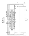
(A) preliminarily forming a rubbery layer around an outer periphery of said core to obtain a preliminarily molded body by extrusion molding, (B) placing said preliminarily molded body between at least two mold units of a mold; (C) forming a compressed molding by compression molding said preliminarily molded body in a given shape inside a cavity defined by said at least two mold units; and (D) curing the resulting molding. An apparatus is also disclosed for producing such an insulator by compression molding, which apparatus comprises (A) a preliminary molding unit, (B) a molding unit form forming a compressed molding from the preliminarily molded body in a given shape by using a mold, and (C) a heater for curing the rubber in the rubber layer.
Description
The rubber composition is heated at a given temperature in the space defined by the inner periphery of the
Consequently, insulating property of the joined housings is deteriorated.
comprises the steps of:
Claims (11)
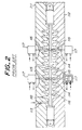
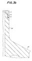
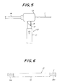
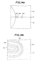
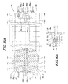
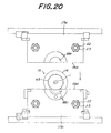
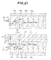
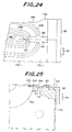
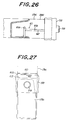
- A process for producing an insulator body by compression molding, said insulator having a core (1) as well as a sheath portion (2) and at least one shed portion (2b) around said sheath portion, said process comprising the steps of:(A) preliminarily shaping a rubber layer (14) of a raw rubber composition around an outer periphery of said core by extrusion molding to obtain a preliminarily molded body;(B) placing said preliminarily molded body between at least two mold units (17a,17b) of a mold (17);(C) forming a compressed molding by compression molding said preliminarily molded body in a given shape inside a cavity defined by said at least two mold units, wherein the internal pressure inside the cavity of the mold is appropriately regulated by means of a rubber-escape groove (60,73,80) connected to the cavity of the mold and provided at a parting interface between the mold units;(D) curing the resulting molding.
- A process according to claim 1 wherein the preliminarily molded body is placed between the upper and lower mold units, and an additional rubber layer is arranged between the upper and lower molds on each of right and left sides of the preliminarily molded body, followed by the compression molding and the curing.
- A process according to claim 1 or 2 wherein before the step (B), the rubber layer shaped in step (A) is removed from the preliminarily molded body at opposite end portions thereof.
- A process according to any one of claims 1 to 3 wherein a long preliminarily molded body is formed and cut into a plurality of preliminarily molded bodies having a given length to be subjected to the steps (B) to (D).
- A process according to any one of the preceding claims wherein when the rubber layer is formed around the outer periphery of the core in step (A), the rubber layer is bonded around the outer periphery of the core.
- A process according to any one of the preceding claims wherein before said preliminary shaping step, the core is washed and dried, and an adhesive is applied to an outer periphery of the core.
- A process according to any one of the preceding claims wherein a burr formed around an outer surface of the insulator is removed.
- A process according to any one of the preceding claims wherein the volume of the rubber layer in the preliminarily molded body is greater than the volume of the cavity of the mold.
- An apparatus for producing an insulator by compression molding, said insulator having a core (1) as well as a sheath portion (2) and at least one shed portion (2b) around said sheath portion, comprising:(A) a preliminary molding unit (13) for preliminarily shaping a rubbery layer (14) of a raw rubber composition around an outer periphery of said core to obtain a preliminarily molded body;(B) a forming unit for forming a compressed molding by placing said preliminarily molded body between at least two mold units (17a,17b) of a mold (17), wherein a rubber-escape groove (60,73,80) is provided at a parting interface between the mold units such that the groove connects to the cavity of the mold, and compression molding said preliminarily molded body in a given shape inside a cavity defined by said at least two mold units;(C) a heater for curing the raw rubber composition.
- Apparatus according to claim 9 wherein each mold unit is constituted by a plurality of molding segments piled and tightened one upon another.
- Apparatus according to claim 9 or 10 wherein at least one of the mold units is provided with at least one groove formed around a boundary edge of a molding face defined by the cavity at a parting face of the mold.
Applications Claiming Priority (7)
| Application Number | Priority Date | Filing Date | Title |
|---|---|---|---|
| JP5068280A JPH0815025B2 (en) | 1993-03-26 | 1993-03-26 | Non-ceramic insulator forming equipment |
| JP68280/93 | 1993-03-26 | ||
| JP6828093 | 1993-03-26 | ||
| JP73926/93 | 1993-03-31 | ||
| JP7392693A JP2607820B2 (en) | 1993-03-31 | 1993-03-31 | Mold and method for molding insulator |
| JP7392693 | 1993-03-31 | ||
| EP94302075A EP0624446B1 (en) | 1993-03-26 | 1994-03-23 | A process and an apparatus for producing insulators |
Related Parent Applications (1)
| Application Number | Title | Priority Date | Filing Date |
|---|---|---|---|
| EP94302075A Division EP0624446B1 (en) | 1993-03-26 | 1994-03-23 | A process and an apparatus for producing insulators |
Publications (2)
| Publication Number | Publication Date |
|---|---|
| EP0873838A2 true EP0873838A2 (en) | 1998-10-28 |
| EP0873838A3 EP0873838A3 (en) | 2000-04-19 |
Family
ID=26409494
Family Applications (2)
| Application Number | Title | Priority Date | Filing Date |
|---|---|---|---|
| EP94302075A Expired - Lifetime EP0624446B1 (en) | 1993-03-26 | 1994-03-23 | A process and an apparatus for producing insulators |
| EP98111847A Ceased EP0873838A3 (en) | 1993-03-26 | 1994-03-23 | A process and an apparatus for producing insulators |
Family Applications Before (1)
| Application Number | Title | Priority Date | Filing Date |
|---|---|---|---|
| EP94302075A Expired - Lifetime EP0624446B1 (en) | 1993-03-26 | 1994-03-23 | A process and an apparatus for producing insulators |
Country Status (6)
| Country | Link |
|---|---|
| US (1) | US5523038A (en) |
| EP (2) | EP0624446B1 (en) |
| CN (1) | CN1056797C (en) |
| AU (1) | AU662856B2 (en) |
| CA (1) | CA2119694C (en) |
| DE (1) | DE69415715T2 (en) |
Cited By (2)
| Publication number | Priority date | Publication date | Assignee | Title |
|---|---|---|---|---|
| EP1260337A1 (en) * | 2001-05-22 | 2002-11-27 | Ngk Insulators, Ltd. | Peeling apparatus of extrusion material batch |
| CN113171955A (en) * | 2021-03-17 | 2021-07-27 | 平高集团有限公司 | Basin-type insulator surface coating curing device |
Families Citing this family (33)
| Publication number | Priority date | Publication date | Assignee | Title |
|---|---|---|---|---|
| JPH08185737A (en) * | 1994-12-28 | 1996-07-16 | Ngk Insulators Ltd | Composite insulator, segment used for manufacturing it, and manufacture of composite insulator using it |
| JP2971774B2 (en) * | 1995-03-20 | 1999-11-08 | 日本碍子株式会社 | Release jig for polymer material mold |
| JP2905416B2 (en) * | 1995-03-20 | 1999-06-14 | 日本碍子株式会社 | End part forming method of composite insulator and end part forming jig used therefor |
| JP2804451B2 (en) * | 1995-03-23 | 1998-09-24 | 日本碍子株式会社 | Compression molding dies for composite insulator production |
| FR2739720B1 (en) * | 1995-10-04 | 1997-12-05 | Schneider Electric Sa | METHOD FOR MANUFACTURING AN INSULATOR AND ISOLATOR CARRIED OUT ACCORDING TO THIS METHOD |
| US5822857A (en) * | 1996-03-18 | 1998-10-20 | Ngk Insulators, Ltd. | Method of repairing shed portion of composite insulator |
| JP2938801B2 (en) * | 1996-03-18 | 1999-08-25 | 日本碍子株式会社 | Manufacturing method of composite insulator and retaining ring of core rod to mold |
| JP3157756B2 (en) * | 1997-10-13 | 2001-04-16 | 日本碍子株式会社 | Molding method of polymer insulator |
| JP2923276B2 (en) * | 1998-01-08 | 1999-07-26 | 日本碍子株式会社 | Mold for molding and handling method |
| US6306331B1 (en) | 1999-03-24 | 2001-10-23 | International Business Machines Corporation | Ultra mold for encapsulating very thin packages |
| US6171091B1 (en) * | 1999-05-12 | 2001-01-09 | Callaway Golf Company | Replaceable mold cavities and mold cavity inserts |
| DE19944513C1 (en) * | 1999-09-16 | 2001-01-25 | Sefag Ag Malters | Extrusion of plastic high-tension insulator involves injection molding insulator rings round a core with split die moving along core |
| US6831232B2 (en) * | 2002-06-16 | 2004-12-14 | Scott Henricks | Composite insulator |
| US6952154B2 (en) | 2002-06-16 | 2005-10-04 | Maclean-Fogg Company | Composite insulator for fuse cutout |
| US20070102098A1 (en) * | 2005-11-09 | 2007-05-10 | Wang Swei M | Method for making shell for electric product |
| CN101609738B (en) * | 2009-07-21 | 2012-08-22 | 国网电力科学研究院武汉南瑞有限责任公司 | Moulding method for insulating part manufacture of high-voltage cable accessory and moulding mold |
| CN102069542A (en) * | 2010-11-04 | 2011-05-25 | 中国西电电气股份有限公司 | Insulation cylinder pouring die |
| CN102118010B (en) * | 2010-12-10 | 2013-08-28 | 上海永锦电气集团有限公司 | Production mould of silicon rubber cable terminal |
| US9731464B2 (en) | 2011-08-10 | 2017-08-15 | Nike, Inc. | Article of footwear formed from two preforms and method and mold for manufacturing same |
| US9096028B2 (en) * | 2011-08-10 | 2015-08-04 | Nike, Inc. | Article of footwear formed from two preforms and method and mold for manufacturing same |
| US10464280B2 (en) | 2011-08-30 | 2019-11-05 | Shanghai Yanfeng Jinqiao Automotive Trim Systems Co. Ltd. | Trim component for vehicle interior |
| CN107263799B (en) | 2011-08-30 | 2019-12-03 | 上海延锋金桥汽车饰件系统有限公司 | A kind of method manufacturing automobile interior component in a mold and the gadget for vehicle interior |
| CN103065745A (en) * | 2011-10-20 | 2013-04-24 | 襄樊国网合成绝缘子股份有限公司 | Mould pressing insulator manufacture method |
| CN102601894B (en) * | 2012-03-06 | 2014-10-15 | 安徽奥丰汽车配件有限公司 | Car dustproof cover forming mould |
| US10093268B2 (en) | 2012-08-27 | 2018-10-09 | Shanghai Yanfeng Jinqiao Automotive Trim Systems Co. Ltd. | Trim component for vehicle interior |
| CN103434059A (en) * | 2013-06-27 | 2013-12-11 | 国家电网公司 | Production mould for insulation sleeve of high-voltage direct current (DC) power transmission equipment |
| CN105023642B (en) * | 2015-07-28 | 2017-01-04 | 远东电缆有限公司 | A kind of the wisdom energy EMUs low-smoke non-halogen flame-retardant high-voltage flexible cable and production technology |
| CN105563712A (en) * | 2016-01-04 | 2016-05-11 | 江苏沙洲电气有限公司 | Production process of cable clamp insulating cover |
| CN106217722A (en) * | 2016-08-04 | 2016-12-14 | 江门市鲁班尼光电科技有限公司 | The manufacture method of anti-water-driven module on a kind of outside wire |
| WO2020006290A1 (en) | 2018-06-28 | 2020-01-02 | Shanghai Yanfeng Jinqiao Automotive Trim Systems Co. Ltd. | Vehicle trim component |
| US11623416B2 (en) * | 2019-06-19 | 2023-04-11 | Arris Composites Inc. | Multi-part molds and methods for forming complex fiber-composite parts |
| CN112590093B (en) * | 2020-11-25 | 2022-06-17 | 贵州红阳机械有限责任公司 | Die for end cover part pressing process and application |
| CN112863787B (en) * | 2021-01-09 | 2022-10-28 | 国网上海市电力公司 | Manufacturing and forming process of electric insulator |
Citations (6)
| Publication number | Priority date | Publication date | Assignee | Title |
|---|---|---|---|---|
| US2435567A (en) * | 1944-10-18 | 1948-02-10 | Columbia Protektosite Company | Method and apparatus for molding wire core temples |
| FR1567954A (en) * | 1967-03-11 | 1969-05-23 | ||
| US4312123A (en) * | 1979-03-12 | 1982-01-26 | Interpace Corporation | Methods of making high voltage electrical insulators and oil-less bushings |
| US4501715A (en) * | 1983-05-18 | 1985-02-26 | Gilbert Barfield | Mold and method for forming golf balls |
| FR2576655A1 (en) * | 1985-01-25 | 1986-08-01 | Alsthom Atlantique | INSULATING HAUBAN |
| JPH05182546A (en) * | 1992-01-08 | 1993-07-23 | Ngk Insulators Ltd | Manufacture of insulator |
Family Cites Families (9)
| Publication number | Priority date | Publication date | Assignee | Title |
|---|---|---|---|---|
| FR2505915A1 (en) * | 1981-05-12 | 1982-11-19 | Ceraver | METHOD FOR MANUFACTURING A COMPOSITE TYPE HAUBAN INSULATOR |
| FR2523361A1 (en) * | 1982-03-15 | 1983-09-16 | Ceraver | Insulating sheath mfr. with corrugated profile - uses circular or trapezoidal section cable wound over sheath while still malleable to form spiral corrugations |
| SU1030862A1 (en) * | 1982-04-22 | 1983-07-23 | Ленинградский Ордена Ленина Политехнический Институт Им.М.И.Калинина | Process for applying rib coating on lengthy article |
| FR2543356B1 (en) * | 1983-03-25 | 1986-01-10 | Ceraver | METHOD AND DEVICE FOR MOLDING THE INSULATING COATING OF A LARGE ORGANIC INSULATOR |
| GB8312892D0 (en) * | 1983-05-11 | 1983-06-15 | Raychem Ltd | Electrical insulator |
| US4724284A (en) * | 1986-01-27 | 1988-02-09 | Lapp Insulator Company | High voltage composite insulator and method of making same |
| FR2596569B1 (en) * | 1986-03-25 | 1988-05-20 | Ceraver | DEVICE FOR RELEASING A COMPOSITE ELECTRICAL INSULATOR |
| US5233132A (en) * | 1986-10-02 | 1993-08-03 | Sediver Societe Europeenne D'isolateurs En | Composite insulator comprising a fiber-resin rod and an insulating coating molded thereover |
| JPH0780207B2 (en) * | 1992-01-23 | 1995-08-30 | 日本碍子株式会社 | Method and apparatus for manufacturing non-ceramic insulator |
-
1994
- 1994-03-16 US US08/213,801 patent/US5523038A/en not_active Expired - Fee Related
- 1994-03-23 DE DE69415715T patent/DE69415715T2/en not_active Expired - Fee Related
- 1994-03-23 CA CA002119694A patent/CA2119694C/en not_active Expired - Fee Related
- 1994-03-23 EP EP94302075A patent/EP0624446B1/en not_active Expired - Lifetime
- 1994-03-23 EP EP98111847A patent/EP0873838A3/en not_active Ceased
- 1994-03-24 AU AU59009/94A patent/AU662856B2/en not_active Ceased
- 1994-03-25 CN CN94103356A patent/CN1056797C/en not_active Expired - Fee Related
Patent Citations (6)
| Publication number | Priority date | Publication date | Assignee | Title |
|---|---|---|---|---|
| US2435567A (en) * | 1944-10-18 | 1948-02-10 | Columbia Protektosite Company | Method and apparatus for molding wire core temples |
| FR1567954A (en) * | 1967-03-11 | 1969-05-23 | ||
| US4312123A (en) * | 1979-03-12 | 1982-01-26 | Interpace Corporation | Methods of making high voltage electrical insulators and oil-less bushings |
| US4501715A (en) * | 1983-05-18 | 1985-02-26 | Gilbert Barfield | Mold and method for forming golf balls |
| FR2576655A1 (en) * | 1985-01-25 | 1986-08-01 | Alsthom Atlantique | INSULATING HAUBAN |
| JPH05182546A (en) * | 1992-01-08 | 1993-07-23 | Ngk Insulators Ltd | Manufacture of insulator |
Non-Patent Citations (1)
| Title |
|---|
| PATENT ABSTRACTS OF JAPAN vol. 017, no. 593 (E-1454), 28 October 1993 (1993-10-28) & JP 05 182546 A (NGK INSULATORS LTD), 23 July 1993 (1993-07-23) * |
Cited By (3)
| Publication number | Priority date | Publication date | Assignee | Title |
|---|---|---|---|---|
| EP1260337A1 (en) * | 2001-05-22 | 2002-11-27 | Ngk Insulators, Ltd. | Peeling apparatus of extrusion material batch |
| CN113171955A (en) * | 2021-03-17 | 2021-07-27 | 平高集团有限公司 | Basin-type insulator surface coating curing device |
| CN113171955B (en) * | 2021-03-17 | 2022-09-30 | 平高集团有限公司 | Basin-type insulator surface coating curing device |
Also Published As
| Publication number | Publication date |
|---|---|
| CN1056797C (en) | 2000-09-27 |
| EP0624446B1 (en) | 1999-01-07 |
| EP0624446A1 (en) | 1994-11-17 |
| CN1094672A (en) | 1994-11-09 |
| AU5900994A (en) | 1994-10-20 |
| US5523038A (en) | 1996-06-04 |
| CA2119694A1 (en) | 1994-09-27 |
| CA2119694C (en) | 1997-11-11 |
| DE69415715D1 (en) | 1999-02-18 |
| AU662856B2 (en) | 1995-09-14 |
| DE69415715T2 (en) | 1999-06-10 |
| EP0873838A3 (en) | 2000-04-19 |
Similar Documents
| Publication | Publication Date | Title |
|---|---|---|
| US5523038A (en) | Process and an apparatus for producing insulators | |
| US5612069A (en) | Apparatus for manufacturing a long non-ceramic insulator in a mold longitudinally shorter than the insulator | |
| US3825457A (en) | Method of mouldig hollow rubber articles | |
| US5811049A (en) | Method for producing composite insulator | |
| JP2824025B2 (en) | Composite insulator and manufacturing method thereof | |
| JPH0815022B2 (en) | Insulator manufacturing method | |
| US3898121A (en) | Apparatus for molding hollow rubber articles | |
| US3879517A (en) | Method for making a dual seal insulator for multiple conductor connectors | |
| KR100615814B1 (en) | Manufacturing process of polymeric insulator | |
| CN113119392A (en) | Shunt extrusion-coated cable insulation connection method | |
| US3930771A (en) | Apparatus for manufacturing a dual seal insulator | |
| CN210190380U (en) | Cable mould that vulcanizes and injection molding was accomplished in step | |
| JP2849349B2 (en) | Electrofusion joint, method of manufacturing the same, and mold for injection molding | |
| CN114454423A (en) | Welding type integral injection molding multi-channel cable jig and using method thereof | |
| JPS61143112A (en) | Method for solid phase extrusion of synthetic resin | |
| JP3012515B2 (en) | CV cable insulation connection method | |
| CN216014934U (en) | High tension cable power line joint department repairs gum cover | |
| CN210791835U (en) | Novel rope saw glue injection mold | |
| CN218615213U (en) | Injection mold of automobile lamp reflection bowl | |
| CN212764370U (en) | Wire fixing leakage-proof sheath vulcanizing mould for precision motor | |
| CN212666607U (en) | Demoulding mechanism for plastic forming mould | |
| KR910003329B1 (en) | Forming apparatus of stress cone | |
| CA2151351A1 (en) | Method and Apparatus for Manufacturing Molded Articles | |
| CN116001322A (en) | RTM forming tool and forming method for guide vane composite material part | |
| JPH06290663A (en) | Molding metal mold for insulator and its molding method |
Legal Events
| Date | Code | Title | Description |
|---|---|---|---|
| PUAI | Public reference made under article 153(3) epc to a published international application that has entered the european phase |
Free format text: ORIGINAL CODE: 0009012 |
|
| AC | Divisional application: reference to earlier application |
Ref document number: 624446 Country of ref document: EP |
|
| AK | Designated contracting states |
Kind code of ref document: A2 Designated state(s): DE FR GB |
|
| PUAL | Search report despatched |
Free format text: ORIGINAL CODE: 0009013 |
|
| AK | Designated contracting states |
Kind code of ref document: A3 Designated state(s): DE FR GB |
|
| 17P | Request for examination filed |
Effective date: 20000615 |
|
| 17Q | First examination report despatched |
Effective date: 20010820 |
|
| GRAG | Despatch of communication of intention to grant |
Free format text: ORIGINAL CODE: EPIDOS AGRA |
|
| STAA | Information on the status of an ep patent application or granted ep patent |
Free format text: STATUS: THE APPLICATION HAS BEEN REFUSED |
|
| 18R | Application refused |
Effective date: 20020728 |