EP0873238B1 - Durch Spritzdruckgiessen hergestelltes Paar von Kunststoffbrillengläsern und Herstellungsverfahren - Google Patents
Durch Spritzdruckgiessen hergestelltes Paar von Kunststoffbrillengläsern und Herstellungsverfahren Download PDFInfo
- Publication number
- EP0873238B1 EP0873238B1 EP96933845A EP96933845A EP0873238B1 EP 0873238 B1 EP0873238 B1 EP 0873238B1 EP 96933845 A EP96933845 A EP 96933845A EP 96933845 A EP96933845 A EP 96933845A EP 0873238 B1 EP0873238 B1 EP 0873238B1
- Authority
- EP
- European Patent Office
- Prior art keywords
- lens
- lenses
- molded
- paired
- mold
- Prior art date
- Legal status (The legal status is an assumption and is not a legal conclusion. Google has not performed a legal analysis and makes no representation as to the accuracy of the status listed.)
- Expired - Lifetime
Links
Images


Classifications
-
- B—PERFORMING OPERATIONS; TRANSPORTING
- B29—WORKING OF PLASTICS; WORKING OF SUBSTANCES IN A PLASTIC STATE IN GENERAL
- B29D—PRODUCING PARTICULAR ARTICLES FROM PLASTICS OR FROM SUBSTANCES IN A PLASTIC STATE
- B29D12/00—Producing frames
-
- B—PERFORMING OPERATIONS; TRANSPORTING
- B29—WORKING OF PLASTICS; WORKING OF SUBSTANCES IN A PLASTIC STATE IN GENERAL
- B29C—SHAPING OR JOINING OF PLASTICS; SHAPING OF MATERIAL IN A PLASTIC STATE, NOT OTHERWISE PROVIDED FOR; AFTER-TREATMENT OF THE SHAPED PRODUCTS, e.g. REPAIRING
- B29C37/00—Component parts, details, accessories or auxiliary operations, not covered by group B29C33/00 or B29C35/00
- B29C37/0003—Discharging moulded articles from the mould
- B29C37/0007—Discharging moulded articles from the mould using means operable from outside the mould for moving between mould parts, e.g. robots
-
- B—PERFORMING OPERATIONS; TRANSPORTING
- B29—WORKING OF PLASTICS; WORKING OF SUBSTANCES IN A PLASTIC STATE IN GENERAL
- B29C—SHAPING OR JOINING OF PLASTICS; SHAPING OF MATERIAL IN A PLASTIC STATE, NOT OTHERWISE PROVIDED FOR; AFTER-TREATMENT OF THE SHAPED PRODUCTS, e.g. REPAIRING
- B29C45/00—Injection moulding, i.e. forcing the required volume of moulding material through a nozzle into a closed mould; Apparatus therefor
- B29C45/17—Component parts, details or accessories; Auxiliary operations
- B29C45/1769—Handling of moulded articles or runners, e.g. sorting, stacking, grinding of runners
-
- B—PERFORMING OPERATIONS; TRANSPORTING
- B29—WORKING OF PLASTICS; WORKING OF SUBSTANCES IN A PLASTIC STATE IN GENERAL
- B29C—SHAPING OR JOINING OF PLASTICS; SHAPING OF MATERIAL IN A PLASTIC STATE, NOT OTHERWISE PROVIDED FOR; AFTER-TREATMENT OF THE SHAPED PRODUCTS, e.g. REPAIRING
- B29C45/00—Injection moulding, i.e. forcing the required volume of moulding material through a nozzle into a closed mould; Apparatus therefor
- B29C45/17—Component parts, details or accessories; Auxiliary operations
- B29C45/40—Removing or ejecting moulded articles
- B29C45/42—Removing or ejecting moulded articles using means movable from outside the mould between mould parts, e.g. robots
-
- B—PERFORMING OPERATIONS; TRANSPORTING
- B29—WORKING OF PLASTICS; WORKING OF SUBSTANCES IN A PLASTIC STATE IN GENERAL
- B29C—SHAPING OR JOINING OF PLASTICS; SHAPING OF MATERIAL IN A PLASTIC STATE, NOT OTHERWISE PROVIDED FOR; AFTER-TREATMENT OF THE SHAPED PRODUCTS, e.g. REPAIRING
- B29C45/00—Injection moulding, i.e. forcing the required volume of moulding material through a nozzle into a closed mould; Apparatus therefor
- B29C45/17—Component parts, details or accessories; Auxiliary operations
- B29C45/46—Means for plasticising or homogenising the moulding material or forcing it into the mould
- B29C45/56—Means for plasticising or homogenising the moulding material or forcing it into the mould using mould parts movable during or after injection, e.g. injection-compression moulding
- B29C45/561—Injection-compression moulding
-
- B—PERFORMING OPERATIONS; TRANSPORTING
- B29—WORKING OF PLASTICS; WORKING OF SUBSTANCES IN A PLASTIC STATE IN GENERAL
- B29C—SHAPING OR JOINING OF PLASTICS; SHAPING OF MATERIAL IN A PLASTIC STATE, NOT OTHERWISE PROVIDED FOR; AFTER-TREATMENT OF THE SHAPED PRODUCTS, e.g. REPAIRING
- B29C45/00—Injection moulding, i.e. forcing the required volume of moulding material through a nozzle into a closed mould; Apparatus therefor
- B29C45/17—Component parts, details or accessories; Auxiliary operations
- B29C45/46—Means for plasticising or homogenising the moulding material or forcing it into the mould
- B29C45/57—Exerting after-pressure on the moulding material
-
- B—PERFORMING OPERATIONS; TRANSPORTING
- B29—WORKING OF PLASTICS; WORKING OF SUBSTANCES IN A PLASTIC STATE IN GENERAL
- B29D—PRODUCING PARTICULAR ARTICLES FROM PLASTICS OR FROM SUBSTANCES IN A PLASTIC STATE
- B29D11/00—Producing optical elements, e.g. lenses or prisms
- B29D11/00009—Production of simple or compound lenses
- B29D11/00413—Production of simple or compound lenses made by moulding between two mould parts which are not in direct contact with one another, e.g. comprising a seal between or on the edges
-
- B—PERFORMING OPERATIONS; TRANSPORTING
- B29—WORKING OF PLASTICS; WORKING OF SUBSTANCES IN A PLASTIC STATE IN GENERAL
- B29D—PRODUCING PARTICULAR ARTICLES FROM PLASTICS OR FROM SUBSTANCES IN A PLASTIC STATE
- B29D11/00—Producing optical elements, e.g. lenses or prisms
- B29D11/00009—Production of simple or compound lenses
- B29D11/00432—Auxiliary operations, e.g. machines for filling the moulds
-
- B—PERFORMING OPERATIONS; TRANSPORTING
- B29—WORKING OF PLASTICS; WORKING OF SUBSTANCES IN A PLASTIC STATE IN GENERAL
- B29D—PRODUCING PARTICULAR ARTICLES FROM PLASTICS OR FROM SUBSTANCES IN A PLASTIC STATE
- B29D11/00—Producing optical elements, e.g. lenses or prisms
- B29D11/00865—Applying coatings; tinting; colouring
-
- B—PERFORMING OPERATIONS; TRANSPORTING
- B29—WORKING OF PLASTICS; WORKING OF SUBSTANCES IN A PLASTIC STATE IN GENERAL
- B29L—INDEXING SCHEME ASSOCIATED WITH SUBCLASS B29C, RELATING TO PARTICULAR ARTICLES
- B29L2011/00—Optical elements, e.g. lenses, prisms
- B29L2011/0016—Lenses
-
- Y—GENERAL TAGGING OF NEW TECHNOLOGICAL DEVELOPMENTS; GENERAL TAGGING OF CROSS-SECTIONAL TECHNOLOGIES SPANNING OVER SEVERAL SECTIONS OF THE IPC; TECHNICAL SUBJECTS COVERED BY FORMER USPC CROSS-REFERENCE ART COLLECTIONS [XRACs] AND DIGESTS
- Y10—TECHNICAL SUBJECTS COVERED BY FORMER USPC
- Y10S—TECHNICAL SUBJECTS COVERED BY FORMER USPC CROSS-REFERENCE ART COLLECTIONS [XRACs] AND DIGESTS
- Y10S425/00—Plastic article or earthenware shaping or treating: apparatus
- Y10S425/808—Lens mold
Definitions
- the field of the present invention is the manufacture of lenses by molding and dipcoating.
- the preferred embodiments of the present invention use a method and apparatus for multi-cavity injection molding of polycarbonate spectacle lens integrated via full automation with dip hardcoating, to produce clean hardcoated molded lens made entirely within a single continuous clean room air enclosure surrounding the lenses, without any human operators therein, nor requiring any cutting or trimming of the molded paired lens or runner system before hardcoating, nor use of cleaning protocols before dipcoating.
- An extension of this clean room enclosure and robotic handling may optionally provide in-line continuous-product-flow automatic inspection of optical power and lens cosmetic quality, and/or may optionally provide in-line continuous-product-flow anti-reflective thin film vacuum coating, before the molded and hardcoated polycarbonate lenses exit out of the continuous clean room air enclosure and/or receive manual handling.
- Vision-corrective plastic ophthalmic prescription spectacle lens having refractive index greater than glass (1.53) or peroxide-crosslinked allyl diglycol carbonate (known as "CR-39”)(1.49-1.5) are known.
- Rx lens Vision-corrective plastic ophthalmic prescription spectacle lens
- Such lenses which may be cast thermoset or injection molded are highly desirable because the wearer of spectacle lenses finds them to be thinner (due to greater light-bending power of high-refractive-index plastic) and lighter (lower specific gravity, particularly in the case of polycarbonate versus CR-39).
- the myopic (“near-sighted") spectacle lens wearer can avoid the cosmetically undesirable appearance of prior art lenses. Lighter weight means better comfort.
- polycarbonate polycarbonate
- polycarbonate will be taken to be inclusive of other optical-grade thermoplastic substitutes, as would be obvious to those skilled in the art.
- US-A-4,008,031 shows apparatus for injection-compression molding Rx lens using what appears to be a two-cavity mold.
- a hanger 20 for use in subsequent dipcoating operations.
- Two molded-on ejector tabs 16 are located at about 10:30-1:00 o'clock positions, with respect to the gate/dripmark location at 6:00 o'clock.
- this location would have the detrimental effect of propagating coating flowout runs along the front and back faces of the molded lens during dipcoating withdrawal, but in Weber's case, he has installed the hanger tab and ejector tabs onto a circumferential flange 12, which is set back from both the front and back lens edges, such that coating flow runoff could then follow this flange from top to bottom of each individually-held lens (provided the lens don't swing from side to side).
- US-A-5,093,049 shows injection-compression molding of Rx lens in a two-cavity mold, with the cavities connected by a cold runner and sprue, with the sprue being able to be mechanically shut off at a predetermined time in the cycle, to prevent backflow.
- the patent is silent on any ejection means for demolding these two lenses and no ejector tabs or pins are shown. If the forward travel of the movable cores, which provide the compression, is limited by hard stops, they cannot be used to drive forward past the parting line once the mold is open, to assist ejection. In that case, a human operator would be relied upon to manually grasp the cold sprue and pull loose the two lenses attached therefor from the mold. No hanger tab is shown or mentioned.
- GB A-2159441 also teaches continuous dip production of scratch-resistant liquid coatings onto plastic optical moldings.
- the optical plastic moldings contemplated are spectacle lenses, and Figure 2 shows a molding with a "lug 10 for clamping purposes is formed thereon and diametrically opposite this lugged end is a dripoff lug 11, so that excessive scratch-resistant coating composition can drip off without forming a ridge when coated and dried".
- These diametrically-opposed hanger tab and drip tab would inevitably have coating flowout runs propagated from the two junctions of the coating tab, at its shoulders. Unfortunately, these runs take place in the very worst location of the perimeter, since the coating flow runs will go directly through the central, most critical zone of the optics for vision (see Figure 2D).
- the lenses produced would not be usable as spectacle lenses, but rather would only be suitable for use as ordinary protective-covering lenses such as watch glasses, scales, and mirrors, none of which are required to have the high quality of image transmission that corrective-vision spectacle lenses must have.
- thermoplastic injection compression molded paired spectacle lenses formed within a moldset having a parting line for opening between an A side and a B side of said moldset, said paired lenses comprising the elements of two thermoplastic injection molded spectacle lens joined into a pair, each of said lens having an outer perimeter forming a lens edge contoured for release out of a lens mold cavity, said outer perimeter comprising four 90-degree quadrants defined in accordance with a clock face; and a cold runner having a sprue connecting therebetween a left lens and a right lens in each pair, said cold runner being formed after molten thermoplastic flow from said sprue in fluid communication with said left lens and said right lens is stopped and then cooling to solidification joins together the lenses into a pair, characterized in that said cold runner is located in the right-band 1:30-4:30 o'clock side quadrant of the left lens and the left-hand 7:30-10:30 o'clock side quadrant of the right lens, and in that an
- the present invention further provides a method of manufacturing thermoplastic injection compression molded paired spectacle lenses according to claim 1, comprising the steps of
- productivity is increased by changing the "unit of transfer" being handled from individual Rx lens of the prior art to paired molded-together Rx lens, which came from the mold ready to be robotically handled by means of the molded-on hanger tab having special design.
- Plastic "flash" at the parting line edges of the paired molded lenses is minimised, so as to prevent dipcoating flow runs propagated off such flash and/or to eliminate any trimming off of flash before dipcoating since such trimming processes generate plastic airborne particulate contaminations.
- the preferred process allows lenses to be demolded cleanly, with ejection processes generating minimal (or none) metal or plastic airborne particulate contaminations.
- the method described below allows for ejecting multi-cavity injection-compression-molded Rx lens, in molded pairs each with a hanger tab, while preserving cleanliness of both the demolded paired lenses and the optically polished molding surfaces of moldset, free of metal or plastic particles.
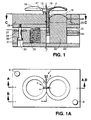
- Figures 1, 1A and 1B show a simplified two-cavity lens moldset, with the injection molding machine nozzle tip (not shown) injecting into a cold sprue bushing 9 and cold runner system 15 which is centered between the two mold cavities.
- An optional but preferred embodiment for molding two or more pairs of Rx lenses during one cycle of a single moldset would employ instead a hot-runner system using a plurality of hot-runner nozzle tips in place of the single injection molding machine nozzle tip which injects into cold sprue bushing 9 and cold runner system 15; such a hot-runner apparatus for a four-cavity mold is shown in US-A-4,828,769.
- Another hot-runner system for optical thermoplastic molding is shown in US-A-4,965,028.
- a cold well 40 is preferably built into the cold sprue and cold runner system to trap "cold slugs" before they reach the lens mold cavities.
- a slight undercut 41 or negative draft angle on cold well 40 will provide a positive mechanical retention force, which is helpful later on in ejection steps.
- the moldset employs "variable volume” mold cavities wherein the initial cavity height dimension is larger before injection starts than the final molded lens thickness dimension.
- a "variable volume” mold cavity moldset apparatus typically uses an injection-compression molding process sequence to mold the Rx lens, wherein a driving force squeezes the injected melt sometime after injection starts to reduce this cavity height dimension.
- a preferred arrangement is shown in US-A-4,828,769.
- Parting line "flash” plastic spilled out of the moldset along the parting line where the A side and B side of the moldset joins
- Parting line "flash” plastic spilled out of the moldset along the parting line where the A side and B side of the moldset joins
- dipcoating thus generating particulates
- Use of extremely stiff, high-deflection-force conventional coil-type die springs as resilient member to solve that problem creates a different problem during the ejection phase of the molding cycle since as soon as the clamping force is released in preparation for mold opening, these high spring forces act as a catapult for the lenses and cold runner by prematurely pushing forward the parting line molding surfaces before the injection molding machine's ejection mechanism is actuated.
- the present invention preferably employs a novel combination of two different types of moldsprings within the moldset to give "2 stage" workings of these "resilient members".
- a conventional coil-type steel die spring 25 having long compression stroke lengths but moderate deflection force are used in combination with an extremely stiff, very high deflection force stack of Belleville spring washers 26 held in place by shoulder bolt 29, to give two different levels of moldspring forces during ten different phases of the stroke length.
- the 2-stage springload combination is an improved form of "resilient member" operating within any such variable-volume injection compression mold in which the cavity height is determined by the degree of elongation of springs.
- the process of molding using the above tool has the steps of:
- the resulting molded lens should be shape-stable (the plastic molecules will have memory. Since molding productivity is enhanced by faster heat transfer rates between the cooling melt and the mold inserts, it may be advantageous to employ highly-conductive copper-based alloys, with a hard electroplated chrome or nickel face on the optically-polished partforming surfaces, as materials for construction of the mold inserts, as shown in US-A-4,793,953 and US-A-5,376,317.
- the first step of demolding and ejection of the paired lens starts with releasing clamping forces applied by the injection molding machine, thereby decompressing and extending the resilient member comprising the combined springs described above.
- Fig. 1B righthand split view, showing the molded lens 16 has already been separated off the B side core insert 14 optically-polished partforming surface, creating a release space 17 between the concave lens surface and the convex insert surface upon which it was formed.
- This release space 17 substantially corresponds to the compression strokelength 21 dimension, when the moldset spring is extended or uncompressed by releasing mold clamping forces exerted by the injection molding machine during the very start of the ejection phase of the cycle.
- drafted sleeve surface 19 forming the lens edge uses thermal shrinkage of the molded lens to assist separation off the mold cavity bore (sleeve 20) surfaces.
- these lenses could be so strongly held onto the B side mold insert 14 by partial vacuum that the lenses are pulled back when the springloaded parting line B side mold plate 28 comes forward (relative to the B side mold insert).
- Applicants have seen such examples, where the still-hot gates are bent or, even worse, torn off, leaving the lens stuck onto the B side insert deep inside the bore.
- the molded paired lenses are already transferred off the B side and are being pulled off the optically-polished partforming surfaces of the A side concave inserts 13 , since the cold sprue (18) and cold runner 15 of the molded paired lenses are still firmly attached to the ejector mechanism (which is not yet actuated as a result of this controlled-draft-angle on the cold well 40 of the sprue) which "grips" the molded paired lenses 16 onto the B side. (Also, deliberately running the coolant temperatures on the B side cooler than those of the A side can cause more shrinkage to occur on the B side of the molded lenses, thus reducing retention forces on the A side of the lens.)
- the paired molded lenses 16 and connecting cold runner system including mechanical retention 41 are stripped off the B side by conventional ejector pins 4, which are driven by motions of the injection molding machine's hydraulic ejector cylinder (not shown) tied into the moldset ejector plates 24, to which the ejector pins 4 are mechanically tied in. Stripping the lenses off the B side will also be mechanically positive. This step is done only when the moldset is fully opened up along the parting line, and timing of this ejector motion is only initiated after the end-of-arm tooling of a takeout robot is in place to receive the molded paired lenses while being stripped off of the mechanical retention.
- This timing is coordinated between a programmable control of the injection molding machine and of the takeout robot, with part verification to confirm that this handoff has been made.
- a side entry type is preferred over the more common "up and out" rectilinear type, since the space above the mold platens is preferably where downward-facing HEPA filters will be located, and since a clean room enclosure will be smaller and more compact if a side entry type is used.
- Typical makers of side entry takeout robots include Ranger Automation of Shrewsbury, MA, Conakry Martin of Agawam, MA, and Automated Assemblies of Clinton, MA.
- filtered compressed air is employed in accordance with a prescribed "air blow" sequence of steps in order to provide a supplementary driving force for separating the molded lens off the optically polished part-forming surfaces, to which they are held by natural vacuum due to thermal shrinkage while the mold is closed and the clamping force is maximized.
- filtered compressed air for cleanliness of part-forming mold surfaces as well as molded lens surfaces
- a side air line (10) and B side air line (11) is introduced by A side air line (10) and B side air line (11), into the clearance gap 12 formed between the outer perimeter of each cavity insert (A side cavity insert 13 and B side core insert 14 and the bore of circumferentially-surrounding sleeve 20.
- Air valves control the air flow and pressure within air lines (10) and (11) to provide air blow in an ejection sequence, working in combination with conventional ejector pins 4, which are driven by motions of the injection molding machine's hydraulic ejector cylinder (not shown) tied into the moldset ejector plates 24, to which the ejector pins 4 are mechanically tied in.
- filtered compressed air feeds through these "vent gap” -sized passageways gap 12 (for polycarbonate lens, a gap of 0.25mm (0.001 inch) still will not “flash"), so that the forces or the air begin to be applied on the movable platen B side (core side) around the perimeter of the convex insert, and work inward toward the center of the lens, to provide a clean separation of the convex part-forming surfaces of the B side insert.
- drafted surface 19 of the lens edge uses thermal shrinkage of the molded lens to assist separation off the mold cavity bore (sleeve 20) surface.
- a second stage of air blowoff can be initiated. wherein similarly filtered air enters up around the perimeter of the concave optically-polished A side mold insert perimeter and driving toward each lens center to break the partial vacuum formed during molding. During this time a substantial seal is still held by a tiny edge seal overlap 42 of the lens front onto the lens mold cavity perimeter.
- Each polycarbonate dipcoated lens is inherently edge-gated and is hardcoated by a glossy film which is easily seen to form a "dripmark" resulting from gravity flow of the liquid dipcoating onto both front and back surfaces.
- the location of any lens' dripmark is arbitrarily designated as in the 6 o'clock position.
- lens samples typically show one or more ejector tabs, most commonly 180 degrees opposite the gate.
- the molded paired lenses of the preferred embodiment of the present invention will have no hanger tabs 1 in the upper 90-degree quadrant 6 (between 10:30 and 1:30 o'clock), will be gated 4 within right and/or left side quadrants 5 (between 1:30 and 4:30 o'clock or between 7:30 and 10:30 o'clock. If they use an (optional) drip tab (not shown), it will be located in lower quadrant 7 (between 4:30 o'clock and 7:30 o'clock).
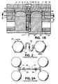
- Fig. 2 shows a simplified 2-cavity lens molding of the prior art with a cold sprue and runner 32. Note that each lens has a multiplicity of ejector tabs and the gate, each of which must be cut 33 in a separate operation after demolding before dipcoating, using molded-on "T" shaped hanger tab 34.
- the prior art patent which most closely resembles this Fig. 2 is (US-A-4,008,031), differing only in that the T-shaped hanger tab 20 is located directly opposite the gate 25 , with an ejector tab 16 on each side of tab 20.
- Fig. 2A shows a simplified 4-cavity lens molding with cold sprue 18' and runner 35 feeding into 2 pairs each of lenses, each having a gate 15'.
- Figure 9B shows drip tabs 99 in the 6:00 o'clock position of the molded lenses, but that even if there was a way of separating the two molded pairs shown without cutting after solidification of the plastic, the small cold well 31 is not located high enough to clear the lens edge so as to serve as a gripper or hanger tab for dipcoating, nor can cold-runner firm sprue 19 be separated without a cutting operation, which would generate plastic dust contaminants.
- Fig. 2C a typical prior art single lens with tab 34 at 12:00 o'clock position is shown. If dipcoating immersion strokelength is not extremely accurate, and the lens is immersed not just to the top lens edge but further, partway up the stem of the tab, then the liquid will run back down by gravity this stem, thus causing flow runs (38) streaming back onto the lens' optical faces. This is minimized but not entirely eliminated by reducing the tab thickness and setting tab 34 back some distance from either face. as shown in US-A-4,008,031.
- a GB-A-2159441 single lens with a tab 34 of the full thickness of the lens, at 12:00 o'clock position is shown.
- Fig. 2 of GB-A-2159441 from which this lens is taken showing lens F with lug 10 and driptab 11.
- dipcoating immersion strokelength is not extremely accurate (which is impossible with endless conveyor dipping the lens)
- the lens will inevitably be immersed partway up the stem of the tab, and the liquid will run back down by gravity this stem, thus causing a large flow runs 38 streaming back onto the lens' optical faces.
- this surface's draft angle will be a positive value, when compared to vertical ("zero draft").
- This draft angle generally should be increased in value directly proportionally as lens edge thickness is increased.
- adding a slight molded-on rim at the junction of the convex surface and lens edge sidewall (typically, no more than 0.5mm per side is sufficient) which acts as a edge seal 42 (see Fig. 1B) facilitates compressed-air blowoff which is optional but preferred with the present invention.
- Molded or cast Rx lens blanks are sold in nominal diameters, rounded off to integral millimeters. Since all cast or molded plastic spectacle lens blanks are subsequently cut down on their perimeters so as to fit inside a specific spectacle frame of the patient's or prescribing doctor's choice, inherently all Rx lenses will be "laid out” to fit the mating spectacle frame. Because of various blemishes and flaws which can accumulate at the edge of cast Rx lens (such as bubbles or voids) and molded plastic lens (such as residual knit line or gate blush) or, due to the dip hardcoating (such as "dripmark"), the rule of thumb is to provide a waste zone, consisting of a perimeter band of 5mm wide circumferentially around the lens edge. Thus, on a 76mm-nominal-diameter lens blank, for layout purposes, only the inner 66mm would be considered usable, when subtracting 5mm waste zone per side.
- the present invention utilizes the fact that waste zone exists in order to alter lens product edge and sidewall details for improved manufacturability.
- Figs. 1, 1A and 1B Most specifically, in an optional but preferred embodiment of the present invention, Applicants provide for a plurality of interchangeable sleeves 20, each of which can be selected with its different drafted surfaces 19 and assembled together with the appropriate mating convex insert 14 in order to mold each different lens power, so as to provide the cleanest possible release of the molded paired lenses free of solid metal or plastic particulates being generated by the ejection process. No one such sleeve draft angle or surface geometry can be optimum for all Rx FSV lens molding, which must encompass a wide range of product geometries.
- the present invention employs interchangeable mold sleeves 20 which become the part-forming surfaces for the lens' sidewall edge.
- interchangeable mold sleeves 20 By interchanging one set of such sleeves having a certain pre-determined drafted surface 19 with another set having a different predetermined drafted surface/angle so as to mate with the corresponding B-side inserts for a specific desired FSV-power minus lens, one can controllably increase or decrease the draft angle of the resulting molded paired lenses for the full range of FSV lenses as they are ejected, for cleanest molded-lens quality.
- the thicker the lens edge, and correspondingly higher minus power the greater the draft angle that should be applied, but preferably only part way down the sleeve.
- a - 2.00 Diopter lens may have an edge thickness of 4.2 mm, and it will release cleanly with a drafted edge of only 1.9 mm.
- a -5.00 Diopter FSV lens having a nominal edge thickness of 14.6mm has clean release by using an increased drafted edge of 7.2mm.
- paired lens as described above are formed within multicavity injection-compression molds are solidified therein, demolding is done within a clean room enclosure maintained preferably at a positive pressure (vs. ambient) from HEPA blower units.
- a take-out robot is needed, preferably, the side-entry type, so that modular blowers supplying HEPA-filtered air can be located directly above the platens onto the molding machine, to maintain a preferably positive-air-pressure within the clean room enclosure which substantially surrounds the mold (a deliberate gap located under the mold for an air exhaust may improve the downward-directed laminar flow pattern; similarly, a bottom gap for directed air exhaust is preferably located below the dipcoating machinery).
- This side-entry takeout robot operates within a clean-room-enclosed tunnel between the enclosed mold and an enclosed HEPA-filtered automated dipcoating machine.
- each pair of lens are ejected forward into gripping jaws of end-of-arm tooling mounted on the side-entry takeout robot's arm.
- this robotic dipcoating machine with its self-contained, clean-room-filtered air, positive-pressure HEPA filter will be located between two such injection molding machines and multi-cavity molds, with two such side-entry robots feeding paired lenses into this one robotic dipcoating machine.
- duo line in-line system, may be economically preferred embodiment versus a single molding machine and mold fed to a single coating machine, since typically Rx lens molding cycles are relatively long (1-5 minutes, depending upon Rx lens power and corresponding molding thickness). With longer-cycling lenses, the duo line configuration de-bottlenecks the molding step, for increased capacity output per unit of capital equipment cost.
- the robotic device or dipcoating machine may take a number of conventional forms with automated transport driven by chain-drive conveyors (operating singly or in parallel, connected by crossbars whereon the lensholder racks would be hung), or, alternatively, an indexable overhead conveyor or walking-beam conveyor.
- An optional but preferred embodiment employs a programmable SCARA cylindrical-type robot of the kind manufactured by IBM, GMF Fanuc, and Seiko.
- Such a SCARA robot should have a suitably-large (typically, up to 270 degrees rotation and at least 100mm Z axis) work envelope, so as to be able to transfer these molded paired Rx lenses from a hand-off point somewhere inside the coating machine clean-room enclosure to at least one hardcoating diptank, wherein a computer-programmable sequence of immersion times and withdrawal speeds can be employed, followed by transfer to a holding device which is part of a curing workstation fitted with conveying means therein.
- a suitably-large (typically, up to 270 degrees rotation and at least 100mm Z axis) work envelope so as to be able to transfer these molded paired Rx lenses from a hand-off point somewhere inside the coating machine clean-room enclosure to at least one hardcoating diptank, wherein a computer-programmable sequence of immersion times and withdrawal speeds can be employed, followed by transfer to a holding device which is part of a curing workstation fitted with conveying means therein.
- Fig. 3 shows a paired molded lenses with hanger tab 1 comprising stem 3 and head 4, as they are received from the side-entry takeout robot, directly or indirectly handed off to the second robotic device.
- dashed line 39 showing the liquid level of the dipbath -- everything below that line 39 will be immersed in the hardcoating solution.
- the workholder mating horseshoe-shaped head's contoured surfaces (lead angle taper 50), detent 52, insertion lead angle 53 are preferably located above the liquid level 39, so as to not contaminate downstream area where mechanical mating might dislodge coating flakes.
- Figs 3C and 3D show the gripping pairs of robotic devices for handling the lenses.
- the devices are preferably fitted with a rotary wrist (not shown) capable of rotationally moving 70 about axis 69.
- the paired gripping jaws (43 left and 60 right) can move together 68 to grip or ungrip, in accordance with program control.
- Fig. 3C shows the jaws are cut as substantially mirror-images of the head surface contours but with additional clearances (63 vertical and 62 horizontal) provided for imprecise robotic "handoffs" when transferring the paired molded lenses from one workstation or operation step to another.
- Such clearances provide tolerance for slight misalignments or positional errors, yet complete the pickup or handoff properly.
- the gripping orientation shown in Fig. 3C is how the SCARA robot would hold the paired molded lenses during the dipcoating step's lowering and raising operations, after which the wet lenses can then be placed into one of the multiple workholder arms having a substantially-mated mirror-image-machined "nest" of Fig. 3B having tapered angle 50', and stem placement relief 57 and stem retention step 58, with stem clearance 56.
- a workholder will be then used to automatically transport the wet lens through drying and curing steps.
- Means for such automatically transport can be conventional conveyors, but in an optional but preferred embodiment, a rotary index drive is fitted with many such workholder arms, as a carousel within the curing workstation.
- the gripping orientation shown in Fig. 3D is how the SCARA robot would hold the paired molded lenses during the insertion of the head into a lensholder rack or similar fixture, wherein the receiving nest (not shown) has a protruding surface for mechanical interference with head detent surface 52 to prevent the head from being easily dislodged during transport. Insertion then requires the robot to exert a pushing force in the axial direction of the stem toward the head, sufficient to deflect the spring.
- the lead angle surfaces 53 assist in this friction fit, as does the spring relief 51 (the greater the relief and the thinner the legs, the easier to deflect the horseshoe shaped spring). Removal is the reverse of the insertion.
- this insertion will be done after the paired dipcoated lenses have been cured (at least to a tackfree state), then inserted into a rack holding many pairs, for transport manually after leaving the clean room to such other downstream "batch” operations as inspections (by humans), degating and packaging.
- Another optional, but preferred, embodiment uses an intermediate step of robotically placing the molded paired Rx lens into a circulating filtered alcohol tank for a prescribed residence time therein, to perform the following functions:
- an optional, but preferred, embodiment for use of the alcohol bath would not allow complete evaporation of the alcohol wet film off the molded paired Rx lens before immersion into the liquid hardcoating dipbath. Instead, wet alcohol films should remain on the lens when immersed into the dipbath, where the lenses are kept for a sufficiently-long residence time so as to remove any remaining wet-film of alcohol (and any airborne particles which may have became entrained therein during the transfer time from alcohol bath to dipcoating bath).
- Displacing wet-films of alcohol on the lenses' surface with the liquid hardcoating bath is achieved by a combination of high rate of internal circulation of the liquid hardcoating, as well as same programmed-in mechanical motion by the robotic arm holding the lenses to provide agitation and turbulence.
- Such liquid solvent-based hardcoating compositions ideally suited for this protocol and for use with the SCARA robot will also be of low-to-moderate viscosity (preferably, ⁇ 10 centistoke; most preferably, ⁇ 5 cs.), so as to give efficient mixing/removal of the, wet alcohol film off the lens within the dipbath without entraining air bubbles, and to easily flow out smoothly after any vibrations from the SCARA dipping motions.
- low-to-moderate viscosity preferably, ⁇ 10 centistoke; most preferably, ⁇ 5 cs.
- Another way to get smooth coatings from such unconventionally thin viscosity (2-10 cs.) dipbaths is to employ unconventionally fast withdrawal speeds at least 508 mm (20 inches) per minute, preferably 12.7-127mm (0.5-5 inches) per second, most preferably 25.4-76.2mm (1-3 inches) per second (conventional dipbaths of> 10 cs. use 50.8-304.8mm (2-12 inches) per minute), and to follow the first dip with at least a second dip.
- the dipbath should be relatively fast-drying (by choosing selected high-evaporation-rate solvents, such as low molecular weight alcohols and ketones), so as to give smooth coatings free of coating flow runs or "sags", while using relatively dilute (typically ⁇ 25% solids) dipbath with a moderate-to-low hardcoating polymer molecular weight.
- the curing workstation will be configured so as to provide the desired cure protocol.
- a simplest version would be a solvent-free UV-curable hardcoating, in which case the curing workstation might simply consist of a battery of UV lamps of the electrodeless type (made by Fusion Systems of Rockville, Maryland) or conventional mercury-arc UV lamps, with the lenses having been robotically placed onto carriers of suspended from an overhead conveyor, so as to present the paired, molded lenses' front and back surfaces to line-of-sight exposure to these UV lamps for a sufficiently-long time to effect desired cure.
- the curing workstation might simply consist of a battery of UV lamps of the electrodeless type (made by Fusion Systems of Rockville, Maryland) or conventional mercury-arc UV lamps, with the lenses having been robotically placed onto carriers of suspended from an overhead conveyor, so as to present the paired, molded lenses' front and back surfaces to line-of-sight exposure to these UV lamps for a sufficiently-long time to effect desired cure.
- the curing workstation might simply consist of a battery of UV lamps of the electrodeless type (made by Fusion Systems of Rockville, Maryland) or conventional mercury-
- a tackfree state might be desired in order to re-cycle flawed coated lenses -- any inspected lenses which have coating flaws can be easily recycled by immersion into a suitable solvent to strip the tackfree, gelled coating which is not yet fully crosslinked, thus removing the flawed coating film and allowing the paired molded lenses to again be fed through the cleaning and dipcoating protocol.
- An optional but preferred embodiment of a curing workstation may employ a rotary indexing table fitted with multiple arms, having either grasping jaws, suction cups or sculptured mechanical nests, adapted for receiving the molded paired Rx lenses that have molded-on hanger tabs.
- An especially preferred embodiment employs the SCARA robot to precisely place the head of the hanger tab into a substantially mechanically mating geometry (preferably with a tapered lead-angle fit) nest of the type shown in Fig. 3B , and located near the end of each of these arms.
- a further optional but preferred embodiment of this special type of curing workstation would then allow for a settable rotation of the arm, such that the position of the molded, paired Rx lens can be varied from a "straight down" vertical orientation (wherein the molded, paired lenses hanging vertically direct down from the arm, at a 90-degree angle), and by rotation of the arm, this angle can be successively reduced to some minimal angle of perhaps 10 degrees or so below the horizontal orientation.
- This optional, but preferred, embodiment has the advantage of employing gravity to create a more uniform coating flowout pattern distributed all across the lens surface.
- the lenses are then robotically transferred into an adjoining extension of the same cleanroom enclosure which contains an automated computer-assisted-vision lens inspection system, for cosmetic inspection.
- automated lens inspection machines typically use pattern recognition computer software with a video and/or laser-scanning noncontact inspection, and make comparison of the resulting image against the computer's decision rules for "go" and "no-go” acceptance of any cosmetic flaw deviations.
- an optical computerized inspection system for cosmetics relies upon high-resolution imagery and a large proportion of all cosmetic rejects are at the surface of the hardcoated lenses ("coating clear specks" and "coating flowout runs", especially).
- One such manufacturer of Rx FSV lens automated inspection machines is Non-Contact International, of Maumee, Ohio.
- Yet another optional but preferred embodiment of the present invention takes the hardcoated lens to full crosslinked state before leaving the curing workstation, then robotically transfers the molded fully-cured hardcoated paired Rx lens within an adjoining extension of this mated clean-room enclosure maintained under positive pressure (HEPA-filtered air of typically Class 100 purity), wherein this connected-clean-room enclosure contains a thin-film anti-reflective ("AR") vacuum-coating machine fitted with multiple load locks and product workholders adapted to the molded, hardcoated, paired lenses.
- a continuous-process anti-reflective vacuum coating system would typically contain the following steps:
- Such a continuous-process automated-transfer AR-coating machine would be directly analogous to similar machines used by the hundreds for continuous-process aluminum-sputter-coating onto injection-molded polycarbonate compact discs .
- Leading vacuum-coating equipment manufacturers as Leybold, Balzers, and Denton Vacuum have provided such machines for integrated-molding-and-coating of compact discs (CDs).
- a known batch process for production of lenses comprises multicavity injection/compression molding of Rx lenses and robotic takeout of full shot (cold runner) onto a conveyor belt system.
- the lenses are then manually cut to remove runners or gates or tabs and loaded into a lens holder rack. These lenses form work-in-progress inventory.
- the lenses are then cleaned using a CFC or multistage aqueous drying process, are dip coated with a liquid hard coat material, and are then UV or heat cured to cross-link the coating material.
- the Rx lenses are multicavity injection/compression molded, preferably in pairs and are then removed robotically with grippers mated to a hanger tab.
- the lenses undergo an optional alcohol bath immersion destaticizing, cooling and cleaning stage.
- the lenses are then dip coated with liquid hard coat material, which is then crosslinked with UV or heat cure.
- the lenses may be subject to the application of an inline reflective coating and/or inline automatic inspection.
- the various stages in the case of embodiments of the invention are carried out in a single clean room environment.
Claims (2)
- Paar durch ein thermoplastisches Spritzdruckgießen gebildeter Kunststoffbrillengläser (16), gebildet innerhalb eines Formsatzes, der eine Unterteilungslinie zum Öffnen zwischen einer A-Seite und einer B-Seite des Formsatzes besitzt, wobei die gepaarten Brillengläser (16) die Elemente aufweisen: zwei thermoplastische, spritzgegossene Brillengläser (16), die zu einem Paar verbunden sind, wobei jedes Brillenglas (16) einen äußeren Umfang besitzt, der eine Brillenglaskante bildet, die mit Kontur zum Freigeben aus einem Brillenglas-Formhohlraum versehen ist, wobei der äußere Umfang vier 90 Grad Quadranten aufweist, die entsprechend einer Uhrfläche gebildet sind; und einen Kalteingusskanal (15), der einen Einguss (18) besitzt, der sich zwischen einem linken Brillenglas und einem rechten Brillenglas in jedem Paar verbindet, wobei der Kalteingusskanal (15) gebildet wird, nachdem geschmolzener Thermoplast von dem Einguss (18) in einer Flüssigkeitsverbindung mit dem linken Brillenglas und dem rechten Brillenglas unterbrochen ist und dann abgekühlt ist, um verfestigt die Brillengläser zu einem Paar miteinander zu verbinden, dadurch gekennzeichnet, dass der Kalteingusskanal (15) in dem rechtsseitigen Quadranten (5) einer Uhr bei 1:30-4:30 des linken Brillenglases und in dem linksseitigen Quadranten (5) einer Uhr bei 7:30-10:30 des rechten Brillenglases angeordnet ist und dass eine integral geformte Aufhängungslasche (1) im Wesentlichen äquidistant zwischen dem rechten Brillenglas und dem linken Brillenglas der gepaarten Brillengläser angeordnet ist, wobei die Aufhängungslasche (1) einen Schaft (3) besitzt, der im Wesentlichen vertikal aus dem Kalteingusskanal (15) heraus ansteigt, die gepaarten Brillengläser (16) miteinander verbindend, und einen Kopf (4) besitzt, der an dem Schaft (3) an einem Punkt oberhalb einer höchsten Brillenglaskante angeordnet ist, wenn die gepaarten Brillengläser (16) vertikal in einer Eintauch-Position gehalten sind, wobei der Kopf (4) so geformt ist, um geometrisch mit Robotereinrichtungen zum Ergreifen, in Benutzung, des Kopfs (4) zu passen, um dadurch zu verhindern, dass eine Flüssigkeits-Tauchhartbeschichtung die Robotereinrichtung berührt, wodurch die entformten Brillengläser leicht, ohne Schneiden oder Trimmen, tauchbeschichtet werden.
- Verfahren zum Herstellen von einem Paar Brillengläser (16) durch thermoplastisches Spritzdruckgießen nach Anspruch 1, das die Schritte aufweist:a) Bilden mindestens eines geformten Paars von Brillengläsern (16) innerhalb gepaarter Formhohlräume mit variablem Volumen, die eine Hohlraumhöhe besitzen, die durch erweiterbare, elastische Elemente in dem Spritzdruckgießsatz bestimmt ist, wobei die Formhohlräume optisch polierte Teile bildende Oberflächen (19) auf gegenüberliegenden, gepaarten, ersten konvexen Seiteneinsätzen und zweiten konkaven Seiteneinsätzen haben, wobei die Formhohlräume entlang eines Seitenquadranten des Brillenglases und einer Flüssigkeitsverbindung mit einer Spritzgießquelle aus geschmolzenem Thermoplast mit Kantenöffnungen versehen sind, angeordnet im Wesentlichen äquidistant zwischen den Formhohlräumen, um eine Unterteilungslinie eines Kalteingusses und eines Kalteingusskanals zu bilden, wenn zugelassen wird, dass sich der Kalteinguss (18) und der Kalteingusskanal (15), die eine mechanische Retention an einer Seite der Unterteilungslinie haben, abkühlen,
wobei sich mindestens eine Aufhängungslasche pro Paar geschmolzener Brillengläser von dem Kalteinguss (18) und dem Kalteingusskanal (15) erstreckt,
und wobei die geformten, gepaarten Brillengläserkanten (16) eine abgefaste Fläche haben, die für eine saubere Freigabe von Bohrungen der Formhohlräume geeignet ist;b) Kühlen der geformten, gepaarten Brillengläser (16), bis der Thermoplast formstabil ist;c) Auswerfen der geformten, gepaarten Brillengläser durch:(i) Verringern von Formklemmkräften, die entlang der Unterteilungslinie ausgeübt sind, bis die Formklemmkräfte geringer als eine Kraft sind, die durch die elastischen Elemente ausgeübt wird, um so die elastischen Elemente zu erweitern, um dadurch die geformten, gepaarten Brillengläser von den optisch polierten Teile bildenden Oberflächen der konvexen Einsätze der ersten Seite zu trennen und einen Freigaberaum zu erzeugen, bevor sich die Unterteilungslinie, gebildet zwischen der ersten Seite und der zweiten Seite, trennt,(ii) Ziehen der geformten, gepaarten Brillengläser aus den optisch polierten Teile bildenden Oberflächen der konkaven Einsätze der zweiten Seite heraus, wenn die Unterteilungslinie beginnt, sich zu trennen, während mechanisch die geformten, gepaarten Brillengläser auf der ersten Seite zurückgehalten werden,(iii) Abstreifen der geformten, gepaarten Brillengläser von der mechanischen Retention der ersten Seite, wenn der Formsatz entlang der Unterteilungslinie vollständig offen ist, nur nachdem ein Werkzeug mit einem Armende eines Herausnahmeroboters an Ort und Stelle ist, um die geformten, gepaarten Brillengläser aufzunehmen.
Priority Applications (1)
| Application Number | Priority Date | Filing Date | Title |
|---|---|---|---|
| EP04019928A EP1524099B1 (de) | 1995-09-25 | 1996-09-20 | Tauchbeschichten von Kunststoffbrillengläsern |
Applications Claiming Priority (3)
| Application Number | Priority Date | Filing Date | Title |
|---|---|---|---|
| US08/533,126 US5718849A (en) | 1995-09-25 | 1995-09-25 | Method and apparatus for injection-compression molding & ejecting paired thermoplastic spectacle lens suited for fully automated dip hardcoating |
| US533126 | 1995-09-25 | ||
| PCT/US1996/015141 WO1997011826A1 (en) | 1995-09-25 | 1996-09-20 | Molding, ejecting and dipcoating thermoplastic spectacle lens |
Related Child Applications (1)
| Application Number | Title | Priority Date | Filing Date |
|---|---|---|---|
| EP04019928A Division EP1524099B1 (de) | 1995-09-25 | 1996-09-20 | Tauchbeschichten von Kunststoffbrillengläsern |
Publications (3)
| Publication Number | Publication Date |
|---|---|
| EP0873238A1 EP0873238A1 (de) | 1998-10-28 |
| EP0873238A4 EP0873238A4 (de) | 1999-11-24 |
| EP0873238B1 true EP0873238B1 (de) | 2006-06-07 |
Family
ID=24124597
Family Applications (2)
| Application Number | Title | Priority Date | Filing Date |
|---|---|---|---|
| EP96933845A Expired - Lifetime EP0873238B1 (de) | 1995-09-25 | 1996-09-20 | Durch Spritzdruckgiessen hergestelltes Paar von Kunststoffbrillengläsern und Herstellungsverfahren |
| EP04019928A Expired - Lifetime EP1524099B1 (de) | 1995-09-25 | 1996-09-20 | Tauchbeschichten von Kunststoffbrillengläsern |
Family Applications After (1)
| Application Number | Title | Priority Date | Filing Date |
|---|---|---|---|
| EP04019928A Expired - Lifetime EP1524099B1 (de) | 1995-09-25 | 1996-09-20 | Tauchbeschichten von Kunststoffbrillengläsern |
Country Status (15)
| Country | Link |
|---|---|
| US (5) | US5718849A (de) |
| EP (2) | EP0873238B1 (de) |
| JP (1) | JP4105226B2 (de) |
| KR (1) | KR100269553B1 (de) |
| CN (3) | CN1066678C (de) |
| AT (1) | ATE328724T1 (de) |
| AU (1) | AU705735B2 (de) |
| BR (1) | BR9610683A (de) |
| CA (1) | CA2232952C (de) |
| DE (1) | DE69636229T2 (de) |
| ES (1) | ES2260772T3 (de) |
| HK (2) | HK1039593B (de) |
| RU (1) | RU2147005C1 (de) |
| TW (2) | TW315386B (de) |
| WO (1) | WO1997011826A1 (de) |
Families Citing this family (91)
| Publication number | Priority date | Publication date | Assignee | Title |
|---|---|---|---|---|
| US6129042A (en) * | 1996-11-08 | 2000-10-10 | Coburn Optical Industries, Inc. | Process and machine for coating ophthalmic lenses |
| US6287488B1 (en) * | 1998-02-02 | 2001-09-11 | Thomas J. Dougherty | Method for injection molding of high quality parts |
| US7002744B2 (en) * | 1999-11-22 | 2006-02-21 | Younger Mfg. Co. Dba Younger Optics | Polarized optical part using high impact polyurethane-based material |
| US6440335B1 (en) | 1998-12-30 | 2002-08-27 | Sola International, Inc. | Process for molding thermoplastic lenses and, steeply curved and/or thin lenses produced thereby |
| US6284162B1 (en) | 1999-03-25 | 2001-09-04 | Sola International, Inc. | Molding method for manufacturing thin thermoplastic lenses |
| FR2790993B1 (fr) * | 1999-03-17 | 2001-06-15 | Essilor Int | Procede de demoulage d'un article en materiau polymere transparent et son utilisation pour la fabrication d'un article en materiau polymere transparent tel qu'une lentille ophtalmique |
| US6592356B1 (en) | 1999-05-05 | 2003-07-15 | Johnson & Johnson Vision Care, Inc. | Mold, molding system and molding machine for making ophthalmic devices |
| US6869549B2 (en) * | 1999-05-05 | 2005-03-22 | Johnson & Johnson Vision Care, Inc. | Method and mold for making ophthalmic devices |
| US6270698B1 (en) | 1999-05-25 | 2001-08-07 | American Greetings Corp. | Stress-relieved acrylic optical lenses and methods for manufacture by injection coining molding |
| US6220703B1 (en) | 1999-12-29 | 2001-04-24 | Younger Manufacturing Co., Inc. | Ophthalmic lenses utilizing polyethylene terephthalate polarizing films |
| US6432327B2 (en) | 1999-12-29 | 2002-08-13 | Younger Mfg. Co. | Formed polyethylene terephthalate polarizing film for incorporation in optical-grade plastic parts |
| US6759090B2 (en) * | 1999-12-29 | 2004-07-06 | Younger Mfg. Co. | Method for improved adhesion of an optical coating to a polarizing film |
| US6500376B1 (en) | 2000-01-27 | 2002-12-31 | Visteon Global Technologies, Inc. | Multiple injection compression molding process |
| KR100357745B1 (ko) * | 2000-06-09 | 2002-10-25 | 대명광학 주식회사 | 안경 렌즈용 하드코팅장치 |
| US20030211188A1 (en) * | 2000-06-19 | 2003-11-13 | Kachnic Edward F. | Wireless image processing method and device therefor |
| CN1447742A (zh) * | 2000-06-19 | 2003-10-08 | 爱德华·卡琴尼克 | 部件成形机的集成控制器 |
| US6592355B2 (en) * | 2000-12-16 | 2003-07-15 | Ovalon Vision Solutions, Llc | Part-forming machine having an in-mold integrated vision system and method therefor |
| US20040059452A1 (en) * | 2000-08-23 | 2004-03-25 | Edward Kachnic | Sensory inspection system and method thereof |
| US6387441B1 (en) * | 2000-09-06 | 2002-05-14 | Optima, Inc. | Optical lens coating apparatus and method |
| US20030078658A1 (en) * | 2001-01-25 | 2003-04-24 | Gholam-Reza Zadno-Azizi | Single-piece accomodating intraocular lens system |
| US6678097B2 (en) * | 2001-05-04 | 2004-01-13 | Honeywell International Inc. | Non-planar fresnel reflector arrays, mold structures and mold patterns for eliminating negative draft during molding |
| JP3838227B2 (ja) * | 2002-08-06 | 2006-10-25 | セイコーエプソン株式会社 | レンズ保持治具 |
| DE10251146A1 (de) * | 2002-10-31 | 2004-06-03 | Schott Glas | Fertigungslinie zur Herstellung beschichteter, gewölbter Substrate |
| JP4204308B2 (ja) * | 2002-12-19 | 2009-01-07 | 日精エー・エス・ビー機械株式会社 | プリフォームの冷却装置 |
| US20040222540A1 (en) * | 2003-05-06 | 2004-11-11 | Weymouth Russell F. | In-line lens manufacturing |
| US20060284326A1 (en) * | 2003-05-06 | 2006-12-21 | Weymouth Russell F Jr | In-line lens manufacturing |
| NL1023365C2 (nl) * | 2003-05-08 | 2004-11-09 | Fountain Patents B V | Werkwijze en inrichting voor het vervaardigen van voertuigonderdelen. |
| JP4391801B2 (ja) * | 2003-11-10 | 2009-12-24 | Hoya株式会社 | 保護フィルム付き光学レンズ基材および光学レンズ基材の製造方法 |
| EP1689573A4 (de) * | 2003-11-20 | 2011-02-09 | William A Nicol | Sensorsystem und verfahren dafür |
| US20050236727A1 (en) * | 2004-04-23 | 2005-10-27 | Niewels Joachim J | Method and apparatus for mold component locking using active material elements |
| JP4780937B2 (ja) * | 2004-06-18 | 2011-09-28 | Hoya株式会社 | 成形型の設計方法、成形型及び成形型の製造方法 |
| CN1715980A (zh) * | 2004-07-02 | 2006-01-04 | 鸿富锦精密工业(深圳)有限公司 | 非球面镜片及其制造方法 |
| WO2006013744A1 (ja) * | 2004-08-02 | 2006-02-09 | Konica Minolta Opto, Inc. | 光学部品の製造装置 |
| SG156686A1 (en) * | 2004-10-28 | 2009-11-26 | Nypro Inc | System, device, and method for producing thin plastic lenses |
| JP4730307B2 (ja) * | 2004-10-29 | 2011-07-20 | コニカミノルタオプト株式会社 | プラスチックレンズの製造装置 |
| US20070010303A1 (en) * | 2005-07-05 | 2007-01-11 | Nokia Corporation | High quality optical windows for mobile phones and cameras |
| CN100528499C (zh) * | 2005-11-26 | 2009-08-19 | 鸿富锦精密工业(深圳)有限公司 | 一种夹持装置 |
| JP4380629B2 (ja) * | 2005-12-28 | 2009-12-09 | トヨタ自動車株式会社 | 成形品の金型 |
| WO2008023502A1 (fr) * | 2006-08-25 | 2008-02-28 | Konica Minolta Opto, Inc. | Film optique, procédé de fabrication de celui-ci et plaque polarisante utilisant le film optique |
| US20080179770A1 (en) * | 2007-01-31 | 2008-07-31 | Rooney Thomas R | Free form ophthalmic lens mold |
| KR100901109B1 (ko) * | 2007-04-30 | 2009-06-08 | 이명종 | 소형 렌즈케이스의 사출성형방법 및 사출성형물 |
| FR2917416B1 (fr) * | 2007-06-13 | 2012-08-10 | Essilor Int | Procede de traitement de la surface d'un substrat a base de polymere soufre destine a etre recouvert par un revetement |
| FI121742B (fi) * | 2007-07-04 | 2011-03-31 | Theta Optics Ltd Oy | Menetelmä optisen tuotteen valmistamiseksi ja laitteisto |
| CN101344600B (zh) * | 2007-07-13 | 2011-01-26 | 鸿富锦精密工业(深圳)有限公司 | 镀膜镜片的制作方法 |
| US8153035B2 (en) * | 2007-07-24 | 2012-04-10 | Gentex Optics, Inc. | Programmable wetting controller |
| US7942523B2 (en) * | 2007-09-24 | 2011-05-17 | Qspex Technologies, Inc. | Method for manufacturing polarized ophthalmic lenses |
| CN101544034A (zh) * | 2008-03-28 | 2009-09-30 | 鸿富锦精密工业(深圳)有限公司 | 模具定位结构 |
| CN101618589B (zh) * | 2008-06-30 | 2012-09-19 | 鸿富锦精密工业(深圳)有限公司 | 镜片模具 |
| TWI414409B (zh) * | 2008-12-12 | 2013-11-11 | Hon Hai Prec Ind Co Ltd | 鏡座成型模具 |
| WO2010098188A1 (ja) * | 2009-02-25 | 2010-09-02 | コニカミノルタオプト株式会社 | 射出成形用金型装置 |
| EP2437921B1 (de) | 2009-06-03 | 2021-11-17 | Otto Wiesmayer | Verfahren zum herstellen eines formteils |
| DE102009027646A1 (de) * | 2009-07-13 | 2011-01-20 | Evonik Röhm Gmbh | Vorrichtung und Verfahren zur Herstellung dickwandiger Kunststoffformteile mit verringerten Einfallstellen durch Spritzgießen oder -prägen |
| US8298459B2 (en) | 2009-10-21 | 2012-10-30 | International Business Machines Corporation | Spin-mounted fabrication of injection molded micro-optics |
| US9079369B2 (en) * | 2009-10-21 | 2015-07-14 | International Business Machines Corporation | Enhanced separation of injection molded microlenses for high volume manufacturing |
| CN102072608B (zh) * | 2009-11-25 | 2012-10-24 | 财团法人工业技术研究院 | 冷冻系统除霜器的加热装置及其电源供应装置 |
| US8182723B2 (en) * | 2010-06-22 | 2012-05-22 | Advanced Green Energy Tech. Corp. | Multi-cavity injection molding method for fabricating solar lenses |
| US8443859B2 (en) * | 2010-09-18 | 2013-05-21 | A. Raybond Et Cie | Bonding tool for attaching prepared adhesive to bonding part |
| JP5154675B2 (ja) * | 2011-06-08 | 2013-02-27 | シャープ株式会社 | 樹脂成形装置および樹脂成形方法 |
| FR2977330B1 (fr) * | 2011-07-01 | 2018-02-02 | Johnson Controls Automotive Electronics Sas | Procede de fabrication d'un element optique, element optique, et dispositif d'affichage |
| CN102528047B (zh) * | 2011-11-22 | 2016-03-16 | 扬州市海力精密机械制造有限公司 | 粉末冶金精整机 |
| US9233511B2 (en) * | 2012-05-10 | 2016-01-12 | Optiz, Inc. | Method of making stamped multi-layer polymer lens |
| EP2891906A4 (de) * | 2012-08-31 | 2016-05-11 | Hoya Corp | Verfahren zur herstellung einer optischen linse |
| US9914252B2 (en) * | 2012-09-18 | 2018-03-13 | Konica Minolta, Inc. | Molding die, optical element manufacturing method, and optical element |
| US9566724B2 (en) * | 2013-10-30 | 2017-02-14 | Nike, Inc. | Automated rubber molding and de-molding |
| CN104210068B (zh) * | 2014-08-28 | 2017-11-07 | 厦门珈昕偏光科技有限公司 | 一种模具及一种偏光镜片的制造方法 |
| CN107000282B (zh) * | 2014-12-01 | 2019-11-26 | 沙特基础工业全球技术有限公司 | 块状件模具 |
| GB2533408B (en) * | 2014-12-19 | 2020-03-11 | Coopervision Int Holding Co Lp | Method and apparatus relating to manufacture of molds for forming contact lenses |
| KR101694025B1 (ko) * | 2015-07-02 | 2017-01-06 | 현대자동차주식회사 | 박막형 사출 성형 스킨 제조 장치 및 이의 스킨 취출 방법 |
| JP6637780B2 (ja) * | 2016-02-12 | 2020-01-29 | 日本電産サンキョー株式会社 | レンズ成形金型用の入れ子およびこれを備えたレンズ成形用金型 |
| KR101822565B1 (ko) * | 2016-02-26 | 2018-01-26 | 서울과학기술대학교 산학협력단 | 핫 러너를 적용한 렌즈용 사출 성형품 |
| JP6702009B2 (ja) * | 2016-06-16 | 2020-05-27 | コニカミノルタ株式会社 | 表示部材の表面処理方法、表示部材及び表示部材の表面処理装置 |
| JPWO2018092624A1 (ja) * | 2016-11-16 | 2019-10-17 | コニカミノルタ株式会社 | 表示部材、ヘッドアップディスプレイ装置及び治具 |
| CN109983391A (zh) * | 2016-11-16 | 2019-07-05 | 柯尼卡美能达株式会社 | 显示部件、平视显示装置及夹具 |
| CN108237116A (zh) * | 2018-01-23 | 2018-07-03 | 滁州英诺信电器有限公司 | Pc材料镀膜前的清洗工艺 |
| MX2020009708A (es) * | 2018-03-22 | 2021-01-08 | Tokuyama Corp | Metodo para producir una lente de plastico que tiene una capa de recubrimiento. |
| CN108580399A (zh) * | 2018-06-11 | 2018-09-28 | 重庆阿罗网络科技有限公司 | 基于互联网的建材用展示平台的数据录入终端 |
| CN109940816A (zh) * | 2019-03-29 | 2019-06-28 | 江苏丁是丁精密科技有限公司 | 一种弹簧自动化模具 |
| JP7313483B2 (ja) * | 2019-05-17 | 2023-07-24 | キヤノンバージニア, インコーポレイテッド | 製造方法および射出成形システム |
| US11408589B2 (en) | 2019-12-05 | 2022-08-09 | Optiz, Inc. | Monolithic multi-focus light source device |
| CN111633930B (zh) * | 2020-04-27 | 2022-04-15 | 海安迪斯凯瑞探测仪器有限公司 | 一种基于模具识别定位的高精度合模系统 |
| JP2023529241A (ja) | 2020-06-01 | 2023-07-07 | アイケアーズ メディカス インコーポレイテッド | 両面非球面回折多焦点レンズ、その製造、および使用 |
| CN111588440B (zh) * | 2020-06-01 | 2024-01-26 | 李雯雯 | 一种骨科钻孔瞄准辅助定位架 |
| CN112387703A (zh) * | 2020-10-23 | 2021-02-23 | 刘晓芳 | 一种电路板加工的无尘区域用风淋室 |
| CN113103518B (zh) * | 2021-04-13 | 2023-06-20 | 苏州赛普生物科技股份有限公司 | 制备高精密深孔板的多腔模具 |
| EP4091791A1 (de) * | 2021-05-19 | 2022-11-23 | Essilor International | Optimierung von prozessparametern für linsen mit mikrolinsendesign |
| CN114012973B (zh) * | 2021-11-11 | 2023-11-21 | 益阳固美诚塑料包装有限公司 | 一种自动切浇口的分层脱模注塑机及其使用方法 |
| CN115042389B (zh) * | 2022-07-18 | 2023-11-28 | 深圳科利盟精密有限公司 | 导光板注塑成型模具 |
| CN115709153B (zh) * | 2022-11-01 | 2024-02-20 | 苏州心锐医疗科技有限公司 | 一种耐久性人工心脏瓣膜的一体式制造方法及装置 |
| CN115958754B (zh) * | 2023-03-16 | 2023-05-09 | 福鼎市鼎程龙机械设备制造有限公司 | 一种冷泡杯成型模具 |
| CN116533460B (zh) * | 2023-07-03 | 2023-10-03 | 宁波大建汽车零部件有限公司 | 一种用于汽车回复反射器加工的无水口注塑模具 |
| CN117428993B (zh) * | 2023-12-20 | 2024-02-27 | 江苏全真光学科技股份有限公司 | 一种变色镜片的注射成型装置 |
Family Cites Families (23)
| Publication number | Priority date | Publication date | Assignee | Title |
|---|---|---|---|---|
| US4036168A (en) * | 1973-09-10 | 1977-07-19 | Omnitech Inc. | Apparatus for coating articles |
| US3956540A (en) * | 1973-09-10 | 1976-05-11 | Omnitech Inc. | Method of coating articles |
| US4008031A (en) * | 1975-08-22 | 1977-02-15 | Weber Hermann P | Apparatus for injection molding lenses |
| US4364878A (en) * | 1978-08-10 | 1982-12-21 | Omnitech Inc. | Method for molding ophthalmic lenses |
| US4254065A (en) * | 1979-04-04 | 1981-03-03 | Ratkowski Donald J | Injection molding of contact lenses |
| GB2050928A (en) * | 1979-05-23 | 1981-01-14 | Omnitech Inc | Method and apparatus for molding ophthalmic lenses without spoilation |
| US4345546A (en) * | 1981-06-15 | 1982-08-24 | Weber Hermann P | Apparatus for coating items |
| US4438159A (en) * | 1982-03-08 | 1984-03-20 | Techsight Corporation | Coating process |
| US4540534A (en) * | 1983-10-11 | 1985-09-10 | American Optical Corporation | Apparatus and method for injection molding lenses |
| DE8416309U1 (de) * | 1984-05-26 | 1985-03-28 | Opticproduct GmbH + Co Vertriebs KG, 6100 Darmstadt | Kompakte vorrichtung zur kontinuierlichen kratzfestbeschichtung von kunststoff-formkoerpern |
| US4664854A (en) * | 1986-01-06 | 1987-05-12 | Neolens, Inc. | Injection molding equipment and method |
| US4828769A (en) * | 1986-05-05 | 1989-05-09 | Galic/Maus Ventures | Method for injection molding articles |
| US4956028A (en) * | 1986-11-14 | 1990-09-11 | Explosive compositions | |
| US4965028A (en) * | 1987-09-04 | 1990-10-23 | Galic/Maus Ventures | Method of injection molding thermoplastic through multiple gates |
| US4836960A (en) * | 1987-10-05 | 1989-06-06 | Sola Usa, Inc. | Fabrication of thermoplastic optical components by injection/compression molding |
| US4933119A (en) * | 1987-10-13 | 1990-06-12 | Gentex Corporation | Molding apparatus and method |
| US4793953A (en) * | 1987-10-16 | 1988-12-27 | Galic/Maus Ventures | Mold for optical thermoplastic high-pressure molding |
| JPH0729350B2 (ja) * | 1988-07-18 | 1995-04-05 | アイダエンジニアリング株式会社 | プレス加圧を伴う射出成形方法 |
| US4981634A (en) * | 1989-05-22 | 1991-01-01 | Galic Maus Ventures | Injection molding process operating without opening the mold to airborne contaminants |
| US5146228A (en) * | 1990-01-24 | 1992-09-08 | The Johns Hopkins University | Coherent correlation addition for increasing match information in scene matching navigation systems |
| US5164228A (en) * | 1991-05-20 | 1992-11-17 | Bmc Industries, Inc. | Method of applying scratch-resistant coatings to plastic ophthalmic lenses |
| US5376317A (en) * | 1992-12-08 | 1994-12-27 | Galic Maus Ventures | Precision surface-replicating thermoplastic injection molding method and apparatus, using a heating phase and a cooling phase in each molding cycle |
| US5539971A (en) * | 1993-09-13 | 1996-07-30 | United States Surgical Corporation | Method of manufacturing an endoscope |
-
1995
- 1995-09-25 US US08/533,126 patent/US5718849A/en not_active Expired - Lifetime
- 1995-12-07 TW TW084113020A patent/TW315386B/zh not_active IP Right Cessation
- 1995-12-18 TW TW084113523A patent/TW336191B/zh not_active IP Right Cessation
-
1996
- 1996-09-20 CN CN96198303A patent/CN1066678C/zh not_active Expired - Lifetime
- 1996-09-20 EP EP96933845A patent/EP0873238B1/de not_active Expired - Lifetime
- 1996-09-20 CA CA002232952A patent/CA2232952C/en not_active Expired - Lifetime
- 1996-09-20 CN CN00121798A patent/CN1103677C/zh not_active Expired - Lifetime
- 1996-09-20 BR BR9610683A patent/BR9610683A/pt not_active IP Right Cessation
- 1996-09-20 DE DE69636229T patent/DE69636229T2/de not_active Expired - Lifetime
- 1996-09-20 ES ES96933845T patent/ES2260772T3/es not_active Expired - Lifetime
- 1996-09-20 RU RU98107894A patent/RU2147005C1/ru active
- 1996-09-20 AU AU72420/96A patent/AU705735B2/en not_active Expired
- 1996-09-20 JP JP51351697A patent/JP4105226B2/ja not_active Expired - Lifetime
- 1996-09-20 WO PCT/US1996/015141 patent/WO1997011826A1/en active IP Right Grant
- 1996-09-20 EP EP04019928A patent/EP1524099B1/de not_active Expired - Lifetime
- 1996-09-20 CN CNB031027571A patent/CN100475507C/zh not_active Expired - Lifetime
- 1996-09-20 AT AT96933845T patent/ATE328724T1/de active
- 1996-09-20 KR KR1019980702176A patent/KR100269553B1/ko not_active IP Right Cessation
-
1997
- 1997-02-05 US US08/795,903 patent/US5750060A/en not_active Expired - Lifetime
- 1997-02-05 US US08/795,613 patent/US5750156A/en not_active Expired - Lifetime
-
1998
- 1998-01-20 US US09/009,151 patent/US6024902A/en not_active Ceased
-
2002
- 2002-01-03 HK HK02100043.5A patent/HK1039593B/zh not_active IP Right Cessation
- 2002-02-08 US US10/071,569 patent/USRE40152E1/en not_active Expired - Lifetime
-
2005
- 2005-01-21 HK HK05100594.5A patent/HK1068305A1/xx not_active IP Right Cessation
Also Published As
Similar Documents
| Publication | Publication Date | Title |
|---|---|---|
| EP0873238B1 (de) | Durch Spritzdruckgiessen hergestelltes Paar von Kunststoffbrillengläsern und Herstellungsverfahren | |
| KR100738240B1 (ko) | 안구 디바이스 제조용 몰드 및 성형기 | |
| RU98107894A (ru) | Линза для очков из термопластичного материала, получаемая путем прессования, выталкивания и покрытия погружением | |
| US10029402B2 (en) | Method and apparatus for manufacturing contact lenses | |
| JPH04220323A (ja) | 射出成形体の取出し装置 | |
| AU713238B2 (en) | Molding, ejecting and dipcoating thermoplastic spectacle lens | |
| EP1965968B1 (de) | Verfahren zur herstellung von kontaktlinsen | |
| EP3233412B1 (de) | Verfahren zur herstellung von kontaktlinsen | |
| CN1894089A (zh) | 用于运送眼睛镜片的装置和方法 | |
| MXPA98002350A (en) | Molding, expulsion and coating by immersion of thermoplastic lenses for anteo | |
| JP2612068B2 (ja) | 光学素子のプレス成形装置 | |
| WO2024018208A1 (en) | Method and apparatus relating to manufacture of mold halves for forming contact lenses |
Legal Events
| Date | Code | Title | Description |
|---|---|---|---|
| PUAI | Public reference made under article 153(3) epc to a published international application that has entered the european phase |
Free format text: ORIGINAL CODE: 0009012 |
|
| 17P | Request for examination filed |
Effective date: 19980320 |
|
| AK | Designated contracting states |
Kind code of ref document: A1 Designated state(s): AT CH DE ES FR GB IT LI NL |
|
| RIC1 | Information provided on ipc code assigned before grant |
Free format text: 6B 29D 11/00 A, 6B 29C 45/56 B, 6B 29C 45/27 B |
|
| A4 | Supplementary search report drawn up and despatched |
Effective date: 19991007 |
|
| AK | Designated contracting states |
Kind code of ref document: A4 Designated state(s): AT CH DE ES FR GB IT LI NL |
|
| RAP1 | Party data changed (applicant data changed or rights of an application transferred) |
Owner name: OPTICS TECHNOLOGY, INC. |
|
| 17Q | First examination report despatched |
Effective date: 20010718 |
|
| GRAP | Despatch of communication of intention to grant a patent |
Free format text: ORIGINAL CODE: EPIDOSNIGR1 |
|
| RTI1 | Title (correction) |
Free format text: THERMOPLASTIC INJECTION COMPRESSION MOLDED PAIRED SPECTACLE LENSES AND METHOD OF PRODUCTION |
|
| GRAS | Grant fee paid |
Free format text: ORIGINAL CODE: EPIDOSNIGR3 |
|
| GRAA | (expected) grant |
Free format text: ORIGINAL CODE: 0009210 |
|
| AK | Designated contracting states |
Kind code of ref document: B1 Designated state(s): AT CH DE ES FR GB IT LI NL |
|
| REG | Reference to a national code |
Ref country code: GB Ref legal event code: FG4D |
|
| REG | Reference to a national code |
Ref country code: CH Ref legal event code: EP |
|
| REF | Corresponds to: |
Ref document number: 69636229 Country of ref document: DE Date of ref document: 20060720 Kind code of ref document: P |
|
| REG | Reference to a national code |
Ref country code: CH Ref legal event code: NV Representative=s name: ISLER & PEDRAZZINI AG |
|
| REG | Reference to a national code |
Ref country code: ES Ref legal event code: FG2A Ref document number: 2260772 Country of ref document: ES Kind code of ref document: T3 |
|
| ET | Fr: translation filed | ||
| PLBE | No opposition filed within time limit |
Free format text: ORIGINAL CODE: 0009261 |
|
| STAA | Information on the status of an ep patent application or granted ep patent |
Free format text: STATUS: NO OPPOSITION FILED WITHIN TIME LIMIT |
|
| 26N | No opposition filed |
Effective date: 20070308 |
|
| REG | Reference to a national code |
Ref country code: CH Ref legal event code: PCAR Free format text: ISLER & PEDRAZZINI AG;POSTFACH 1772;8027 ZUERICH (CH) |
|
| REG | Reference to a national code |
Ref country code: FR Ref legal event code: PLFP Year of fee payment: 20 |
|
| PGFP | Annual fee paid to national office [announced via postgrant information from national office to epo] |
Ref country code: CH Payment date: 20150928 Year of fee payment: 20 Ref country code: ES Payment date: 20150928 Year of fee payment: 20 Ref country code: GB Payment date: 20150928 Year of fee payment: 20 |
|
| PGFP | Annual fee paid to national office [announced via postgrant information from national office to epo] |
Ref country code: FR Payment date: 20150917 Year of fee payment: 20 Ref country code: AT Payment date: 20150902 Year of fee payment: 20 |
|
| PGFP | Annual fee paid to national office [announced via postgrant information from national office to epo] |
Ref country code: IT Payment date: 20150923 Year of fee payment: 20 |
|
| PGFP | Annual fee paid to national office [announced via postgrant information from national office to epo] |
Ref country code: DE Payment date: 20150929 Year of fee payment: 20 |
|
| PGFP | Annual fee paid to national office [announced via postgrant information from national office to epo] |
Ref country code: NL Payment date: 20150926 Year of fee payment: 20 |
|
| REG | Reference to a national code |
Ref country code: DE Ref legal event code: R071 Ref document number: 69636229 Country of ref document: DE |
|
| REG | Reference to a national code |
Ref country code: NL Ref legal event code: MK Effective date: 20160919 |
|
| REG | Reference to a national code |
Ref country code: CH Ref legal event code: PL |
|
| REG | Reference to a national code |
Ref country code: GB Ref legal event code: PE20 Expiry date: 20160919 |
|
| PG25 | Lapsed in a contracting state [announced via postgrant information from national office to epo] |
Ref country code: GB Free format text: LAPSE BECAUSE OF EXPIRATION OF PROTECTION Effective date: 20160919 |
|
| REG | Reference to a national code |
Ref country code: AT Ref legal event code: MK07 Ref document number: 328724 Country of ref document: AT Kind code of ref document: T Effective date: 20160920 |
|
| REG | Reference to a national code |
Ref country code: ES Ref legal event code: FD2A Effective date: 20161228 |
|
| PG25 | Lapsed in a contracting state [announced via postgrant information from national office to epo] |
Ref country code: ES Free format text: LAPSE BECAUSE OF EXPIRATION OF PROTECTION Effective date: 20160921 |