EP0872609A2 - Verfahren zur Herstellung mehrschaliger Mauerscheiben - Google Patents
Verfahren zur Herstellung mehrschaliger Mauerscheiben Download PDFInfo
- Publication number
- EP0872609A2 EP0872609A2 EP98890106A EP98890106A EP0872609A2 EP 0872609 A2 EP0872609 A2 EP 0872609A2 EP 98890106 A EP98890106 A EP 98890106A EP 98890106 A EP98890106 A EP 98890106A EP 0872609 A2 EP0872609 A2 EP 0872609A2
- Authority
- EP
- European Patent Office
- Prior art keywords
- bricks
- masonry
- wall
- layer
- pallet
- Prior art date
- Legal status (The legal status is an assumption and is not a legal conclusion. Google has not performed a legal analysis and makes no representation as to the accuracy of the status listed.)
- Granted
Links
Images


Classifications
-
- E—FIXED CONSTRUCTIONS
- E04—BUILDING
- E04C—STRUCTURAL ELEMENTS; BUILDING MATERIALS
- E04C2/00—Building elements of relatively thin form for the construction of parts of buildings, e.g. sheet materials, slabs, or panels
- E04C2/02—Building elements of relatively thin form for the construction of parts of buildings, e.g. sheet materials, slabs, or panels characterised by specified materials
- E04C2/04—Building elements of relatively thin form for the construction of parts of buildings, e.g. sheet materials, slabs, or panels characterised by specified materials of concrete or other stone-like material; of asbestos cement; of cement and other mineral fibres
- E04C2/041—Building elements of relatively thin form for the construction of parts of buildings, e.g. sheet materials, slabs, or panels characterised by specified materials of concrete or other stone-like material; of asbestos cement; of cement and other mineral fibres composed of a number of smaller elements, e.g. bricks, also combined with a slab of hardenable material
- E04C2/042—Apparatus for handling the smaller elements or the hardenable material; bricklaying machines for prefabricated panels
Definitions
- the present invention relates to a method for producing multi-layer wall panels for the construction of buildings.
- a brick masonry fulfills these criteria to a certain extent, they are however, there are limits to the thermal insulation of such masonry. Even when used of highly porous brick material can be carried out without additional thermal insulation measures with a single-layer masonry, the criteria for real low-energy houses not be met.
- DE-A-40 28 884 shows an apparatus and a method for producing vertical wall elements made of bricks.
- the method described is both the mason's workplace and the Move the material supply as well as the wall element in height during bricking. This is very complex and requires an appropriate control that the individual Actuated.
- the height-adjustable working platform is in view critical to the safety of related jobs.
- EP-A-0 456 020 shows a system for mechanical masonry production. A however, such a system is not suitable for the production of multi-layer masonry.
- the object of the present invention is to provide a method for producing a multi-shell Specify masonry in the form of masonry slabs, which is a rational manufacture and transfer enables.
- the wall disc is transported within the production hall on roller conveyors are at the same altitude. Vibrations of the wall disc during manufacture can be largely avoided.
- the process can be carried out in a temperature controlled production hall, whereby the manufacturing conditions and the drying process are precisely controlled can.
- the manufacture of the masonry is extremely efficient, since the upper edge of the Masonry always at the optimal height during the entire manufacturing process about 90 cm.
- the wall disk is produced on a pallet, which on the one hand supports the masonry on a horizontal support surface, and on the other hand provides a vertical stop surface against which the masonry is attached can be pulled up.
- the palette serves for in-house use Further transport for the execution of further processing operations that Drying and storage.
- this instructs on its underside a base share, which is made of interconnected bricks.
- the bricks are preferably glued together, but there are also other mechanical ones Connections possible.
- the base share is made from two rows of bricks, each correspond to an outer layer and if the two rows of bricks through spacer tubes be connected to each other.
- transport bolts are then inserted into the Spacer tubes inserted, and the wall plate is lifted by a hoist that attacks the transport bolt.
- reinforcing bars are made of a feed device that is parallel to the area of the respective upper edge of the masonry this is arranged to be placed on the masonry.
- the feed device consists essentially of a trough, the the balustrade is arranged on the working platform.
- the masonry during the establishment is guided by a movable guide bar on its front is arranged in the area of a parapet of a work platform. This also applies to bricklaying the front surface is precisely defined, which precisely controls the total thickness of the masonry can be.
- the guide bar withdrawn to cause a conflict between the wall washer and the guide rail avoid.
- roles can also be provided be to form the front stop.
- the present invention relates to a masonry wall for buildings that are for one piece Dislocation is determined, consisting of a base share, two outer layers Brick masonry and preferably an insulating inner layer made of glue-bonded mineral light materials, particularly preferably pearlites. If the outer layers out highly porous bricks are manufactured, the inner layer may not be necessary, without getting insulation values that are too low.
- the double-shell construction also brings here Advantages over an equally strong single-layer structure.
- a reinforced mortar layer is arranged on the top is.
- FIG. 1 schematically shows the manufacture of a wall pane the inventive method
- Figure 2 shows a section through a multi-layer Wall plate according to the invention
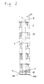
- Fig. 3 is a side view of such a wall plate in the displacement
- Fig. 4 and Fig. 5 details of Fig. 1 each in enlarged Scale.
- a pallet 2 On a lifting table 1, a pallet 2 is arranged, which consists of a horizontal support surface 2a and a vertical stop surface 2b. On such a pallet 2 two Wall washers 3, 4 are made. On a brick pallet 5, the bricks are within easy reach provided and installed by a worker 6. Cut bricks can be separated be fed.
- the lifting table 1 is lowered according to the work process so that the upper edge the masonry stands at an optimal working height of about 90 cm. More, not Feeders, shown in more detail, supply the workplace with mortar or with the Filling material for the inner layer. After the wall is finished, the pallet 2 drawn off via roller conveyors for further processing and drying.
- the wall slice according to the invention is shown in detail.
- the total wall thickness the wall disc is 50 cm.
- the masonry consists of a load-bearing Outer layer 7 with a thickness of 20 cm, an insulating inner layer 8 with a thickness of 17.5 cm and an outer layer 9 with a thickness of 12.5 cm together.
- the outer layer 7 is load-bearing and arranged inside the finished building.
- a base group 10 exists from two rows of bricks 10a and 10b, which consist of bricks glued together and each represent the bottom tile family of the outer layers 7 and 9.
- the two rows of bricks 10a and 10b are through spacer tubes 11 through pre-drilled holes are inserted, connected to each other.
- the lateral cohesion of the masonry as a whole is achieved by means of spacers 12, which are mortared in the grip holes of the individual bricks.
- the inner layer 8 is made of one Insulating filling material made of glue stabilized perlites.
- An empty piping 18 is arranged in the lower section of the inner layer 8.
- the thickness of the outer layer 7 of 20 cm allows the static conditions for four-story building to meet. It can according to the inventive method Wall washers with a total height of 3 m and a length of up to 6 m will.
- FIG. 3 shows the displacement of a wall pane according to the invention.
- the wall disc is not by one of belts or chains 13, which are suspended on a crossbar 14 crane shown in detail raised.
- the straps 13 are fastened to transport bolts 22, which are inserted into the spacer tubes 11.
- the glued joints are Base share 10 designated.
- a parapet is at the work station 16 16a is provided, which has a guide bar 17 which extends to the respective total wall thickness is adjustable.
- the masonry is guided on the one hand by the stop surface 2b, that forms a first stop, and on the other hand of the guide bar 17, the one second stop forms.
- the guide bar 17 is in the thickness direction movable so that there is no obstacle to the movement of the lifting table.
- a receiving shell 19 for the longitudinal reinforcement On the top of the parapet 16b is a receiving shell 19 for the longitudinal reinforcement provided, the receiving shell 19 being designed to be tiltable and the longitudinal reinforcement 20 after completion of a tile coulter simply on the partially made wall disc to be able to tip over.
- the bowl 19 is supplied by a club, not shown, from which the rebar 20 is unwound.
- the wall slab is protected from moisture by an armored mortar layer 21 protected. If necessary, a formwork or receptacle for a floor ceiling can be on the top be trained.
- spacers 11a are welded to the spacer tube 11 are to adjust the distance of the rows of bricks 10a and 10b exactly.
- One between the Tile rows 10a and 10b inserted fabric insert 23 prevents the escape of Filling material downwards.
- the present invention allows the production of high quality wall washers under controlled conditions in a cost-effective and rational way.
Landscapes
- Engineering & Computer Science (AREA)
- Architecture (AREA)
- Civil Engineering (AREA)
- Structural Engineering (AREA)
- Building Environments (AREA)
- Conveying And Assembling Of Building Elements In Situ (AREA)
- Panels For Use In Building Construction (AREA)
- Finishing Walls (AREA)
- Details Of Cameras Including Film Mechanisms (AREA)
- Laminated Bodies (AREA)
Abstract
Description
- Bereitstellen eines Hubtisches, der vertikal beweglich ist;
- Auflegen einer Palette auf den Hubtisch, wobei die Palette eine waagrechte Auflagefläche aufweist;
- Herstellen mindestens einer Basisschar aus miteinander verbundenen Ziegeln auf der Palette;
- Errichtung eines mehrschaligen Mauerwerks auf der Basisschar, bestehend mindestens aus zwei Außenschichten aus Mauerwerk sowie vorzugsweise einer isolierenden Innenschicht, wobei der Hubtisch entsprechend dem Arbeitsfortschritt abgesenkt wird;
- nach Fertigstellung des Mauerwerks Abtransport der Palette zur Weiterverarbeitung, Trocknung und/oder Lagerung.
Claims (14)
- Verfahren zur Herstellung mehrschaliger Mauerscheiben, bestehend aus den folgenden Schritten:Bereitstellen eines Hubtisches (1), der vertikal beweglich ist;Auflegen einer Palette (2) auf den Hubtisch (1), wobei die Palette (2) eine waagrechte Auflagefläche (2a) aufweist;Herstellen mindestens einer Basisschar (10) aus miteinander verbundenen Ziegeln auf der Palette (2);Errichtung eines mehrschaligen Mauerwerks auf der Basisschar (10), bestehend mindestens aus zwei Außenschichten (7, 9) aus Mauerwerk sowie vorzugsweise einer isolierenden Innenschicht (8), wobei der Hubtisch(1) entsprechend dem Arbeitsfortschritt abgesenkt wird;nach Fertigstellung des Mauerwerks Abtransport der Palette (2) zur Weiterverarbeitung, Trocknung und/oder Lagerung.
- Verfahren nach Anspruch 1, dadurch gekennzeichnet, daß die Basisschar (10) aus miteinander verbundenen Ziegeln besteht.
- Verfahren nach Anspruch 2, dadurch gekennzeichnet, daß die Basisschar (10) aus zwei Ziegelreihen (10a, 10b) hergestellt wird, die jeweils einer Außenschicht (7, 9) entsprechen und deren Ziegel untereinander verklebt sind, und daß die beiden Ziegelreihen (10a, 10b) durch Distanzrohre (11) miteinander verbunden werden.
- Verfahren nach Anspruch 3, dadurch gekennzeichnet, daß zwischen den die Basisschar (10) bildenden Ziegelreihen (10a, 10b) eine Gewebeeinlage (23) zum Halten der Innenschicht (8) eingelegt wird.
- Verfahren nach einem der Ansprüche 1 bis 4, dadurch gekennzeichnet, daß die Versetzung der Mauerscheiben erfolgt, indem Gurten (13) an der Basisschar (10) angebracht werden, und die Mauerscheibe an den Gurten (13) aufgehoben wird.
- Verfahren nach einem der Ansprüche 1 bis 5, dadurch gekennzeichnet, daß in die Innenschicht (8) eine Leerverrohrung (18) eingelegt wird.
- Verfahren nach einem der Ansprüche 1 bis 6, dadurch gekennzeichnet, daß Bewehrungseisen (20) aus einer Zufuhreinrichtung (19), die im Bereich der jeweiligen Oberkante des Mauerwerks parallel zu dieser angeordnet ist, auf das Mauerwerk aufgelegt werden.
- Verfahren nach einem der Ansprüche 1 bis 7, dadurch gekennzeichnet, daß das Mauerwerk während der Errichtung durch Rollen (17) an seiner Vorderseite geführt wird, die im Bereich einer Brüstung (16a) einer Arbeitsbühne (16) angeordnet sind.
- Mauerscheibe für Bauwerke, die zur einstückigen Versetzung bestimmt ist, bestehend aus mindestens einer Basisschar (10), zwei Außenschichten (7, 9) aus Ziegelmauerwerk und vorzugsweise einer isolierenden Innenschicht (8) aus leimgebundenen mineralischen Leichtstoffen, besonders vorzugsweise Perliten.
- Mauerscheibe nach Anspruch 9, dadurch gekennzeichnet, daß die Basisschar (10) aus miteinander verbundenen Ziegeln besteht.
- Mauerscheibe nach Anspruch 10, dadurch gekennzeichnet, daß die Basisschar (10) aus zwei Ziegelreihen (10a, 10b) besteht, die jeweils einer Außenschicht (7, 9) entsprechen und deren Ziegel untereinander verklebt sind, und daß die beiden Ziegelreihen (10a, 10b) durch Distanzrohre (11) miteinander verbunden sind.
- Mauerscheibe nach Anspruch 11, dadurch gekennzeichnet, daß zwischen den die Basisschar (10) bildenden Ziegelreihen (10a, 10b) eine Gewebeeinlage (23) zum Halten der Innenschicht vorgesehen ist.
- Mauerscheibe nach einem der Ansprüche 9 bis 12, dadurch gekennzeichnet, daß in der isolierenden Innenschicht (8) eine Leerverrohrung (18) vorgesehen ist, die verschiedene Auslässe durch eine Außenschicht (7, 9) aufweist.
- Mauerscheibe nach einem der Ansprüche 9 bis 13, dadurch gekennzeichnet, daß an der Oberseite eine armierte Mörtelschicht (21) angeordnet ist.
Applications Claiming Priority (3)
| Application Number | Priority Date | Filing Date | Title |
|---|---|---|---|
| AT0063397A AT409395B (de) | 1997-04-14 | 1997-04-14 | Verfahren zur herstellung mehrschaliger mauerscheiben |
| AT633/97 | 1997-04-14 | ||
| AT63397 | 1997-04-14 |
Publications (3)
| Publication Number | Publication Date |
|---|---|
| EP0872609A2 true EP0872609A2 (de) | 1998-10-21 |
| EP0872609A3 EP0872609A3 (de) | 1999-07-14 |
| EP0872609B1 EP0872609B1 (de) | 2003-03-19 |
Family
ID=3495763
Family Applications (1)
| Application Number | Title | Priority Date | Filing Date |
|---|---|---|---|
| EP98890106A Expired - Lifetime EP0872609B1 (de) | 1997-04-14 | 1998-04-09 | Verfahren zur Herstellung mehrschaliger Mauerscheiben |
Country Status (3)
| Country | Link |
|---|---|
| EP (1) | EP0872609B1 (de) |
| AT (2) | AT409395B (de) |
| DE (1) | DE59807508D1 (de) |
Cited By (2)
| Publication number | Priority date | Publication date | Assignee | Title |
|---|---|---|---|---|
| EP1449976A1 (de) * | 2003-02-24 | 2004-08-25 | Undrau Anstalt | Mauertafel-Fertigteil-Element sowie Anlage und Verfahren zur Herstellung desselben |
| EP2826930A1 (de) * | 2013-07-15 | 2015-01-21 | Kappema Fertigteilindustrie GmbH | Vorrichtungen zum Manipulieren von mehrschaligen flächigen Bauteilen |
Citations (2)
| Publication number | Priority date | Publication date | Assignee | Title |
|---|---|---|---|---|
| EP0456020A1 (de) | 1990-05-07 | 1991-11-13 | Anliker, Hedwig | Anlage zur maschinellen Mauerwerksfertigung |
| DE4028884A1 (de) | 1990-09-12 | 1992-03-19 | Konrad Dipl Ing Hofmann | Vorrichtung und verfahren zum herstellen von senkrecht stehenden wandelementen aus mauersteinen |
Family Cites Families (5)
| Publication number | Priority date | Publication date | Assignee | Title |
|---|---|---|---|---|
| DE3227524A1 (de) * | 1982-07-23 | 1984-01-26 | Alfred Dr. 6951 Obrigheim Schach | Verfahren und anlage zur industriellen vorfertigung von massiven mauerwerks-bauteilen aus kuenstlichen steinen |
| WO1984001996A1 (en) * | 1982-11-16 | 1984-05-24 | Jean Focant | Method and device for brick-laying ladles, particularly ladles of metallurgical use |
| DE3246199A1 (de) * | 1982-12-14 | 1984-06-14 | Schach, Alfred, Dr., 6951 Obrigheim | Anlage zur automatisierten vorfertigung von geschosshohem fertigmauerwerk aus kuenstlichen steinen |
| DE3406965A1 (de) * | 1984-02-25 | 1985-08-29 | SÜBA-Cooperation Gesellschaft für Bauforschung, Bauentwicklung und Franchising mbH, 6832 Hockenheim | Halbautomatische versetzeinrichtung fuer bausteine |
| DE4437858A1 (de) * | 1994-10-12 | 1996-04-18 | Robert Stadler | Verfahren und Vorrichtung zum Erstellen von transportablen vertikalen Wänden bzw. Wandteilen aus Mauersteinen |
-
1997
- 1997-04-14 AT AT0063397A patent/AT409395B/de not_active IP Right Cessation
-
1998
- 1998-04-09 AT AT98890106T patent/ATE234976T1/de not_active IP Right Cessation
- 1998-04-09 DE DE59807508T patent/DE59807508D1/de not_active Expired - Fee Related
- 1998-04-09 EP EP98890106A patent/EP0872609B1/de not_active Expired - Lifetime
Patent Citations (2)
| Publication number | Priority date | Publication date | Assignee | Title |
|---|---|---|---|---|
| EP0456020A1 (de) | 1990-05-07 | 1991-11-13 | Anliker, Hedwig | Anlage zur maschinellen Mauerwerksfertigung |
| DE4028884A1 (de) | 1990-09-12 | 1992-03-19 | Konrad Dipl Ing Hofmann | Vorrichtung und verfahren zum herstellen von senkrecht stehenden wandelementen aus mauersteinen |
Cited By (2)
| Publication number | Priority date | Publication date | Assignee | Title |
|---|---|---|---|---|
| EP1449976A1 (de) * | 2003-02-24 | 2004-08-25 | Undrau Anstalt | Mauertafel-Fertigteil-Element sowie Anlage und Verfahren zur Herstellung desselben |
| EP2826930A1 (de) * | 2013-07-15 | 2015-01-21 | Kappema Fertigteilindustrie GmbH | Vorrichtungen zum Manipulieren von mehrschaligen flächigen Bauteilen |
Also Published As
| Publication number | Publication date |
|---|---|
| ATA63397A (de) | 2001-12-15 |
| AT409395B (de) | 2002-07-25 |
| DE59807508D1 (de) | 2003-04-24 |
| ATE234976T1 (de) | 2003-04-15 |
| EP0872609B1 (de) | 2003-03-19 |
| EP0872609A3 (de) | 1999-07-14 |
Similar Documents
| Publication | Publication Date | Title |
|---|---|---|
| EP0674069B1 (de) | Vorrichtung und Verfahren zur Herstellung von Bauwerken unter Verwendung von aus Mauerstein und/oder Schalungen bestehenden Bauteilen | |
| DE1284076B (de) | Verfahren zum Errichten eines Gebaeudes | |
| EP1415057A2 (de) | Gebäude und bauverfahren | |
| DE3036539C2 (de) | Vorrichtung zur Herstellung von Wandelementen zur Vollmontage von Häusern | |
| AT253200B (de) | Verfahren und Vorrichtung zur Herstellung von Mauerwerk aus Bausteinen | |
| EP0872609B1 (de) | Verfahren zur Herstellung mehrschaliger Mauerscheiben | |
| DE10063278C1 (de) | Vorrichtung zum Trennen von aneinander anhaftenden Lagen eines Porenbetonblocks | |
| DE4216367A1 (de) | Vorgefertigtes Mauerelement aus Ziegeln | |
| AT391339B (de) | Verfahren zum herstellen von nichttragenden zwischenwaenden fuer den hochbau | |
| DE10233145A1 (de) | Gebäude und Verfahren | |
| DE1584637C3 (de) | Vorrichtung zum Herstellen einer großformatigen Bauplatte und Verwendung der Vorrichtung | |
| EP1449976A1 (de) | Mauertafel-Fertigteil-Element sowie Anlage und Verfahren zur Herstellung desselben | |
| EP0977927B1 (de) | Verfahren und vorrichtung zur durchführung des verfahrens zum erstellen eines mauerwerks | |
| DE2422586A1 (de) | Fertigbetonteil und verfahren zu dessen herstellung | |
| DE10125665A1 (de) | Vorgefertigtes, transportierbares Wandelement und Verfahren zur Herstellung des Wandelementes | |
| DE2654584A1 (de) | Anlage fuer die vorfertigung grossflaechiger mauersteinwaende | |
| DE1952031A1 (de) | Verfahren zur Herstellung von Spannbetonwaenden fuer Gebaeude | |
| DE2944504C2 (de) | Stahlbetonplatten-Aggregat | |
| EP0945239A2 (de) | Verfahren und Vorrichtung zur Herstellung von Mauerwerk | |
| DE2344719C3 (de) | Vorrichtung zur Vorfertigung von Ziegel-Fertigteilen | |
| DE923995C (de) | Betongeschossdecke mit vorgefertigten Stahlbetonbalken und Fuellkoerpern sowie Hilfsgeraet zum Verlegen der Stahlbetonbalken | |
| DE2914483A1 (de) | Baukonstruktion | |
| DE3246199A1 (de) | Anlage zur automatisierten vorfertigung von geschosshohem fertigmauerwerk aus kuenstlichen steinen | |
| DE3602004A1 (de) | Mauermaschine - verfahren zur ortsunabhaengigen erstellung von mauerwerk mit herkoemmlichen ziegeln aus ueblichen materialien und normalen mauermoerteln einschliesslich aufbringung der ersten putzlage (spritzwurf) | |
| DE2917998A1 (de) | Anlage zur vorfertigung grossflaechiger mauersteinwaende |
Legal Events
| Date | Code | Title | Description |
|---|---|---|---|
| PUAI | Public reference made under article 153(3) epc to a published international application that has entered the european phase |
Free format text: ORIGINAL CODE: 0009012 |
|
| AK | Designated contracting states |
Kind code of ref document: A2 Designated state(s): AT CH DE LI |
|
| AX | Request for extension of the european patent |
Free format text: AL;LT;LV;MK;RO;SI |
|
| PUAL | Search report despatched |
Free format text: ORIGINAL CODE: 0009013 |
|
| AK | Designated contracting states |
Kind code of ref document: A3 Designated state(s): AT BE CH CY DE DK ES FI FR GB GR IE IT LI LU MC NL PT SE |
|
| AX | Request for extension of the european patent |
Free format text: AL;LT;LV;MK;RO;SI |
|
| 17P | Request for examination filed |
Effective date: 19991016 |
|
| AKX | Designation fees paid |
Free format text: AT CH DE LI |
|
| 17Q | First examination report despatched |
Effective date: 20010219 |
|
| GRAG | Despatch of communication of intention to grant |
Free format text: ORIGINAL CODE: EPIDOS AGRA |
|
| GRAG | Despatch of communication of intention to grant |
Free format text: ORIGINAL CODE: EPIDOS AGRA |
|
| GRAH | Despatch of communication of intention to grant a patent |
Free format text: ORIGINAL CODE: EPIDOS IGRA |
|
| GRAH | Despatch of communication of intention to grant a patent |
Free format text: ORIGINAL CODE: EPIDOS IGRA |
|
| GRAA | (expected) grant |
Free format text: ORIGINAL CODE: 0009210 |
|
| AK | Designated contracting states |
Designated state(s): AT CH DE LI |
|
| PGFP | Annual fee paid to national office [announced via postgrant information from national office to epo] |
Ref country code: DE Payment date: 20030319 Year of fee payment: 6 |
|
| REG | Reference to a national code |
Ref country code: CH Ref legal event code: EP |
|
| REF | Corresponds to: |
Ref document number: 59807508 Country of ref document: DE Date of ref document: 20030424 Kind code of ref document: P |
|
| PGFP | Annual fee paid to national office [announced via postgrant information from national office to epo] |
Ref country code: AT Payment date: 20030425 Year of fee payment: 6 |
|
| PG25 | Lapsed in a contracting state [announced via postgrant information from national office to epo] |
Ref country code: LI Free format text: LAPSE BECAUSE OF NON-PAYMENT OF DUE FEES Effective date: 20030430 Ref country code: CH Free format text: LAPSE BECAUSE OF NON-PAYMENT OF DUE FEES Effective date: 20030430 |
|
| REG | Reference to a national code |
Ref country code: CH Ref legal event code: PL |
|
| PLBE | No opposition filed within time limit |
Free format text: ORIGINAL CODE: 0009261 |
|
| STAA | Information on the status of an ep patent application or granted ep patent |
Free format text: STATUS: NO OPPOSITION FILED WITHIN TIME LIMIT |
|
| 26N | No opposition filed |
Effective date: 20031222 |
|
| PG25 | Lapsed in a contracting state [announced via postgrant information from national office to epo] |
Ref country code: AT Free format text: LAPSE BECAUSE OF NON-PAYMENT OF DUE FEES Effective date: 20040409 |
|
| PG25 | Lapsed in a contracting state [announced via postgrant information from national office to epo] |
Ref country code: DE Free format text: LAPSE BECAUSE OF NON-PAYMENT OF DUE FEES Effective date: 20041103 |