EP0839971A2 - Kastenmarkise - Google Patents
Kastenmarkise Download PDFInfo
- Publication number
- EP0839971A2 EP0839971A2 EP97118214A EP97118214A EP0839971A2 EP 0839971 A2 EP0839971 A2 EP 0839971A2 EP 97118214 A EP97118214 A EP 97118214A EP 97118214 A EP97118214 A EP 97118214A EP 0839971 A2 EP0839971 A2 EP 0839971A2
- Authority
- EP
- European Patent Office
- Prior art keywords
- housing
- profile
- awning
- recess
- bolt
- Prior art date
- Legal status (The legal status is an assumption and is not a legal conclusion. Google has not performed a legal analysis and makes no representation as to the accuracy of the status listed.)
- Granted
Links
Images
Classifications
-
- E—FIXED CONSTRUCTIONS
- E04—BUILDING
- E04F—FINISHING WORK ON BUILDINGS, e.g. STAIRS, FLOORS
- E04F10/00—Sunshades, e.g. Florentine blinds or jalousies; Outside screens; Awnings or baldachins
- E04F10/02—Sunshades, e.g. Florentine blinds or jalousies; Outside screens; Awnings or baldachins of flexible canopy materials, e.g. canvas ; Baldachins
- E04F10/06—Sunshades, e.g. Florentine blinds or jalousies; Outside screens; Awnings or baldachins of flexible canopy materials, e.g. canvas ; Baldachins comprising a roller-blind with means for holding the end away from a building
- E04F10/0637—Sunshades, e.g. Florentine blinds or jalousies; Outside screens; Awnings or baldachins of flexible canopy materials, e.g. canvas ; Baldachins comprising a roller-blind with means for holding the end away from a building with mechanisms for adjusting the inclination of the blind
-
- E—FIXED CONSTRUCTIONS
- E04—BUILDING
- E04F—FINISHING WORK ON BUILDINGS, e.g. STAIRS, FLOORS
- E04F10/00—Sunshades, e.g. Florentine blinds or jalousies; Outside screens; Awnings or baldachins
- E04F10/02—Sunshades, e.g. Florentine blinds or jalousies; Outside screens; Awnings or baldachins of flexible canopy materials, e.g. canvas ; Baldachins
- E04F10/06—Sunshades, e.g. Florentine blinds or jalousies; Outside screens; Awnings or baldachins of flexible canopy materials, e.g. canvas ; Baldachins comprising a roller-blind with means for holding the end away from a building
- E04F10/0611—Sunshades, e.g. Florentine blinds or jalousies; Outside screens; Awnings or baldachins of flexible canopy materials, e.g. canvas ; Baldachins comprising a roller-blind with means for holding the end away from a building with articulated arms supporting the movable end of the blind for deployment of the blind
- E04F10/0618—Sunshades, e.g. Florentine blinds or jalousies; Outside screens; Awnings or baldachins of flexible canopy materials, e.g. canvas ; Baldachins comprising a roller-blind with means for holding the end away from a building with articulated arms supporting the movable end of the blind for deployment of the blind whereby the pivot axis of the articulation is perpendicular to the roller
-
- E—FIXED CONSTRUCTIONS
- E04—BUILDING
- E04F—FINISHING WORK ON BUILDINGS, e.g. STAIRS, FLOORS
- E04F10/00—Sunshades, e.g. Florentine blinds or jalousies; Outside screens; Awnings or baldachins
- E04F10/02—Sunshades, e.g. Florentine blinds or jalousies; Outside screens; Awnings or baldachins of flexible canopy materials, e.g. canvas ; Baldachins
- E04F10/06—Sunshades, e.g. Florentine blinds or jalousies; Outside screens; Awnings or baldachins of flexible canopy materials, e.g. canvas ; Baldachins comprising a roller-blind with means for holding the end away from a building
- E04F10/0662—Sunshades, e.g. Florentine blinds or jalousies; Outside screens; Awnings or baldachins of flexible canopy materials, e.g. canvas ; Baldachins comprising a roller-blind with means for holding the end away from a building with arrangements for fastening the blind to the building
-
- E—FIXED CONSTRUCTIONS
- E04—BUILDING
- E04F—FINISHING WORK ON BUILDINGS, e.g. STAIRS, FLOORS
- E04F10/00—Sunshades, e.g. Florentine blinds or jalousies; Outside screens; Awnings or baldachins
- E04F10/02—Sunshades, e.g. Florentine blinds or jalousies; Outside screens; Awnings or baldachins of flexible canopy materials, e.g. canvas ; Baldachins
- E04F10/06—Sunshades, e.g. Florentine blinds or jalousies; Outside screens; Awnings or baldachins of flexible canopy materials, e.g. canvas ; Baldachins comprising a roller-blind with means for holding the end away from a building
- E04F10/0685—Covers or housings for the rolled-up blind
- E04F10/0688—Covers or housings for the rolled-up blind with the housing taking up the articulated arms
Definitions
- the invention relates to a box awning with a housing, a cloth roller arranged in the housing, articulated arms arranged in the housing and a drop bar for retracting and extending the cloth and a holder.
- European patent specification 0 525 248 describes a box awning with an inclination adjustment arranged in the housing and engaging directly on the articulated arms.
- This inclination adjustment has a screw bolt which is provided with mutually opposite threaded sections and is in engagement with a holding arm and a stop means.
- the angle of inclination of the awning can be adjusted by turning the screw bolt.
- this construction also prevents the extended awning from raising when the wind rises.
- due to the mechanical structure there remains a play necessary for the functioning of the box awning, so that lifting of the awning drop bar cannot be completely prevented.
- the German utility model 76 23 881 describes a box awning, in which the tilt adjustment is also arranged within the housing.
- This Inclination adjustment has a threaded bolt which extends through a part of the articulated arm which is pivotally inclined in the housing, so that the inclination of the articulated arm and thus the awning can be adjusted with a screw nut.
- the awning can be raised because there is no lock nut. Because with this construction such a lock nut could only be arranged at a point within the housing that is not accessible from the outside and thus cannot be reached for setting or securing the setting.
- a housing known from German utility model 76 23 881 has a holder in which a square rod fastened to a ceiling engages in a corresponding recess in the housing, a clamp presses the housing against the ceiling from below and thus holds it in position.
- This type of attachment is cumbersome because the heavy housing must be pressed against the ceiling during assembly and at the same time the clips must be attached.
- this assembly which is particularly suitable for limited spaces, still has the disadvantage that the housing must be supported by hand during assembly and in particular during insertion of the latch into the grooves.
- a housing for box awnings is known from European patent specification 0 525 248, the cross section of which is essentially rectangular. This is primarily due to the fact that the housing rests with one or two sides on a wall and / or ceiling and forms part of the holder.
- the invention is therefore based on the technical problem of creating a box awning, the housing of which has comparatively small dimensions, and which can be mounted just as easily as can be adjusted to a certain angle of inclination.
- the tilt adjustment is arranged outside the housing of the box awning on the holder. If the housing of the box awning is arranged on the inclination adjustment, the inclination angle of the housing can be adjusted.
- the articulated arms articulated in the housing are therefore in a fixed angular relationship to the housing and their inclination can only be adjusted together with the housing.
- the reliability and accuracy of the inclination adjustment is thus due to the separation of the inclination adjustment from the mechanics of the articulated arms elevated. Since the articulated arms no longer have to be inclined relative to the housing, a more stable and reliable fastening of the articulated arms in the housing is also possible. The required mechanical play is thus reduced to a minimum, and the drop bar is prevented from being raised or raised.
- the inclination adjustment can have a profile and a threaded bolt that runs through a profile opening. Both the profile and the threaded bolt are pivotally arranged on the bracket, and on both sides of the profile a nut is arranged on the threaded bolt, so that on the one hand an exact adjustment of the inclination of the profile is possible and on the other hand the set inclination can be fixed.
- the housing of the box awning is connected to the bracket via the profile.
- the housing has a hook strip projecting outwards and a recess. If the housing is connected to the profile, the hook strip engages with a corresponding recess in the profile. The hook strip reaches into the recess from above. As a lock, the hook strip has a safety lug and the recess in the profile has a corresponding edge, so that the hook strip cannot slide out of the recess. In the A recess in the housing recess also engages, which in turn is clamped to the profile. This latch is used to lock the housing by preventing the housing from detaching from the profile.
- the invention ensures a stable, reliable and easy-to-use attachment of the box awning.
- the assembly of the housing of the box awning on the holder is also possible according to the invention without the tilt adjustment described, for example if the tilt adjustment is arranged within the housing. In this case too, the assembly has the advantages described above.
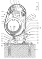
- the box awning 1 has a housing 2 with an upper profile 3 and a lower profile 4.
- a cloth roll 6 which holds a cloth 5 and is rotatably mounted about a horizontal axis.
- two articulated arms 7 are arranged in the housing 2, the inner end 8 of which is rotatably mounted in a joint bearing 9 within the housing 2.
- the outer ends 10 of the articulated arms 7 carry a drop bar 11 to which the cloth 5 is attached.
- the box awning 1 also has a holder 12 with an essentially U-shaped support profile 13 which is fastened to the wall 14 of a building with the aid of fastening elements 15.
- an inclination adjustment 16 is also arranged, which essentially consists of an L-shaped profile 17 and a threaded bolt 18.
- the profile 17 is pivotally mounted with the aid of a cross bolt 19 which extends through two corresponding openings in the cheeks 20 of the support profile 13 and an opening 21 in the profile 17.
- the threaded bolt 18 pivotally mounted on the support profile 13.
- the associated pivot bearing 22 is arranged below the cross pin 19.
- the threaded bolt 18 extends through a vertical longitudinal opening arranged in the profile 17 and carries nuts 23 on both sides of the profile 17. Adjusting the screw nuts 23 thus makes it possible to adjust the angle of inclination of the profile 17.
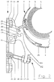
- the housing 2 of the box awning 1 is connected to the bracket 12 and the inclination adjustment 16 as follows.
- the housing 2 essentially has a protruding hook strip 24 and a recess 25.
- the hook strip 24 engages in a corresponding recess 26 from above.
- the hook strip has a safety lug 27 and the recess 26 has a corresponding protruding edge 28 to prevent the hook strip 24 from slipping out of the recess 26.
- the recess 25 in the housing 2 serves to lock the housing 2 with respect to the profile 17.
- a bolt 29 engages in the recess 25.
- the bolt 29 is fastened to the profile 17 with a screw 30.
- the contact surface of the bolt 29 on the profile 17 has a nose 31 about which the bolt 29 rotates during screwing on.
- the end of the bolt 29 which engages in the recess 25 pulls the housing 2 towards the profile 17, while at the same time the other end of the bolt 29 rotates into a recess 32 of the profile 17, in which it finally comes to rest.
- the bolt 29 is - as shown in Fig. 1 - S-shaped, but a C-shaped design is also possible.
- the housing 2 is fastened to the profile 17, then by adjusting the inclination of the profile 17 with the aid of the threaded bolt 18 and the nuts 23 it is possible to change the inclination of the awning, which is mechanically independent of the articulated arms 7.
- the housing 2 and the drop bar lying against the housing essentially result in one round or oval cross section. This results in an aesthetically appealing shape of the housing 2.
Landscapes
- Engineering & Computer Science (AREA)
- Architecture (AREA)
- Civil Engineering (AREA)
- Structural Engineering (AREA)
- Building Awnings And Sunshades (AREA)
- Sheets, Magazines, And Separation Thereof (AREA)
- Packaging Of Annular Or Rod-Shaped Articles, Wearing Apparel, Cassettes, Or The Like (AREA)
- Lasers (AREA)
- Iron Core Of Rotating Electric Machines (AREA)
- Fluid-Damping Devices (AREA)
Abstract
Description
- Die Erfindung betrifft eine Kastenmarkise mit einem Gehäuse, einer im Gehäuse angeordneten Tuchrolle, im Gehäuse angeordneten Gelenkarmen und einer Fallstange zum Ein- und Ausfahren des Tuches und einer Halterung.
- Die europäische Patentschrift 0 525 248 beschreibt eine Kastenmarkise mit einer im Gehäuse angeordneten und direkt an den Gelenkarmen angreifenden Neigungsverstellung. Diese Neigungsverstellung weist einen Schraubbolzen auf, der miteinander entgegengesetzten Gewindeabschnitten versehen ist und mit einem Haltearm sowie einem Anschlagmittel in Eingriff steht. Durch Drehen des Schraubbolzens läßt sich der Neigungswinkel der Markise einstellen. Diese Konstruktion verhindert unter anderem auch ein Hochschlagen der ausgefahrenen Markise bei Aufwind. Jedoch verbleibt infolge des mechanischen Aufbaus ein für das Funktionieren der Kastenmarkise notwendiges Spiel, so daß ein Anheben der Markisenfallstange nicht gänzlich verhindert werden kann.
- Die deutsche Gebrauchsmusterschrift 76 23 881 beschreibt eine Kastenmarkise, bei der ebenfalls die Neigungsverstellung innerhalb des Gehäuses angeordnet ist. Diese Neigungsverstellung weist einen Gewindebolzen auf, der sich durch einen neigungsverschwenkbar im Gehäuse befestigten Teil des Gelenkarmes erstreckt, so daß sich mit einer Schraubenmutter die Neigung des Gelenkarmes und somit der Markise einstellen läßt. Auch hier ist ein Hochschlagen der Markise möglich, da eine Gegenmutter fehlt. Denn eine solche Gegenmutter ließe sich bei diesem Aufbau nur an einer Stelle innerhalb des Gehäuses anordnen, die von außen nicht zugänglich ist und sich somit nicht für ein Einstellen bzw. Sichern der Einstellung erreichen läßt.
- Weiterhin weist ein aus der deutschen Gebrauchsmusterschrift 76 23 881 bekanntes Gehäuse eine Halterung auf, bei der ein an einer Decke befestigter Vierkantstab in eine entsprechende Aussparung im Gehäuse eingreift, eine Klammer das Gehäuse von unten gegen die Decke drückt und somit in seiner Position hält. Diese Art der Befestigung ist umständlich, da das schwere Gehäuse während der Montage gegen die Decke gedrückt werden muß und gleichzeitig die Klammern befestigt werden müssen.
- Aus der deutschen Patentschrift 28 20 177 ist eine bereits verbesserte Halterung bekannt, bei der das Gehäuse zunächst mit einer Bodennut von vorne auf dem Stegrand einer an einer Wand befestigten Klammer plaziert und anschließend in die vorgesehene Lage bewegt wird. Sowohl im Deckel des Gehäuses als auch im oberen Teil der Klammer befinden sich in dieser Lage unmittelbar aneinandergrenzende und einander gegenüberliegende Nuten, in deren gemeinsamen Querschnitt ein Riegel eingeschoben wird, um die Position des Gehäuses zu sichern.
- Diese gerade für begrenzte Raumverhältnisse besonders geeignete Montage besitzt jedoch weiterhin den Nachteil, daß das Gehäuse während der Montage und insbesondere während des Einschiebens des Riegels in die Nuten von Hand abgestützt werden muß.
- Schließlich ist aus der europäischen Patentschrift 0 525 248 ein Gehäuse für Kastenmarkisen bekannt, dessen Querschnitt im wesentlichen rechteckig ist. Dies ist vor allem dadurch bedingt, daß das Gehäuse mit einer oder mit zwei Seiten an einer Wand und/oder Decke anliegt und einen Teil der Halterung bildet.
- Der Erfindung liegt demnach das technische Problem zugrunde, eine Kastenmarkise zu schaffen, deren Gehäuse vergleichsweise geringe Abmessungen besitzt, und die sich ebenso leicht montieren wie auf einen bestimmten Neigungswinkel einstellen läßt.
- Dieses Problem wird erfindungsgemäß zunächst dadurch gelöst, daß die Neigungsverstellung außerhalb des Gehäuses der Kastenmarkise an der Halterung angeordnet ist. Ist das Gehäuse der Kastenmarkise an der Neigungsverstellung angeordnet, so ist ein Verstellen des Neigungswinkels des Gehäuses möglich. Die im Gehäuse angelenkten Gelenkarme befinden sich demnach in einer festen Winkelbeziehung zum Gehäuse und lassen sich in ihrer Neigung nur zusammen mit dem Gehäuse verstellen.
- Erfindungsgemäß ist somit durch die Trennung der Neigungsverstellung von der Mechanik der Gelenkarme die Zuverlässigkeit und Genauigkeit der Neigungsverstellung erhöht. Da die Gelenkarme nicht mehr relativ zum Gehäuse geneigt werden müssen, ist zudem eine stabilere und zuverlässigere Befestigung der Gelenkarme im Gehäuse möglich. Das erforderliche mechanische Spiel verringert sich somit auf ein Mindestmaß, und ein Hochschlagen oder Anheben der Fallstange wird zuverlässig verhindert.
- Die vereinfachte Mechanik der Gelenkarme und deren Befestigung innerhalb des Gehäuses führt schließlich auch zu einer Reduzierung des Platzbedarfs im Gehäuse, so daß sich ein Gehäuse mit entsprechend geringeren Abmessungen ergibt.
- Die Neigungsverstellung kann ein Profil und einen Gewindebolzen aufweisen, der durch eine Profilöffnung verläuft. Sowohl das Profil als auch der Gewindebolzen sind schwenkbar an der Halterung angeordnet, und auf beiden Seiten des Profils ist auf dem Gewindebolzen jeweils eine Mutter angeordnet, so daß einerseits ein genaues Justieren der Neigung des Profils möglich ist und sich andererseits die eingestellte Neigung fixieren läßt.
- Das Gehäuse der Kastenmarkise ist über das Profil mit der Halterung verbunden. Dazu weist das Gehäuse eine nach außen vorstehende Hakenleiste und eine Ausnehmung auf. Ist das Gehäuse mit dem Profil verbunden, steht die Hakenleiste mit einer entsprechenden Ausnehmung des Profils in Eingriff. Dabei greift die Hakenleiste von oben in die Ausnehmung hinein. Als Verriegelung weisen die Hakenleiste eine Sicherheitsnase und die Ausnehmung im Profil eine entsprechende Kante auf, so daß die Hakenleiste nicht aus der Ausnehmung rutschen kann. In die Gehäuseausnehmung greift weiterhin ein Riegel ein, der seinerseits mit dem Profil verklammert ist. Dieser Riegel dient der Verriegelung des Gehäuses, indem er verhindert, daß sich das Gehäuse vom Profil löst.
- Da das Gehäuse mit der vorstehenden Hakenleiste von oben in die entsprechende Ausnehmung im Profil eingehakt wird und danach entlang einer Auflagefläche an dem Profilelement anliegt, ist während des Einbringens des Riegels keine Unterstützung des Gehäuses von unten erforderlich. Zudem benötigt die Montage nicht viel Platz zu beiden Seiten und oberhalb des Markisenkastens.
- Insgesamt gewährleistet die Erfindung eine stabile, zuverlässige und einfach zu handhabende Befestigung der Kastenmarkise.
- Die Montage des Gehäuses der Kastenmarkise an der Halterung ist erfindungsgemäß auch ohne die beschriebene Neigungsverstellung möglich, wenn beispielsweise die Neigungsverstellung innerhalb des Gehäuses angeordnet ist. Auch in diesem Fall weist die Montage die zuvor beschriebenen Vorteile auf.
- Schließlich kann das Gehäuse der Kastenmarkise im eingefahrenen Zustand bei am Gehäuse anliegender Fallstange in Längsrichtung einen im wesentlichen runden oder ovalen Querschnitt aufweisen. Dieser Querschnitt besitzt vor allem den Vorteil, daß keine Wand des Gehäuses eben ausgebildet zu sein braucht, um an einer Wand oder Decke anzuliegen.
- Im folgenden wird die Erfindung anhand eines in der Zeichnung dargestellten Ausführungsbeispiels des näheren erläutert. In der Zeichnung zeigen:
- Fig. 1
- eine Kastenmarkise im eingefahrenen Zustand und
- Fig. 2
- eine Teilansicht kurz vor dem Ineingriffbringen des Gehäuses mit der Neigungsverstellung jeweils im Querschnitt.
- Die Kastenmarkise 1 besitzt ein Gehäuse 2 mit einem oberen Profil 3 und einem unteren Profil 4. Im Inneren des Gehäuses ist eine ein Tuch 5 aufnehmende Tuchrolle 6 angeordnet, die um eine horizontale Achse drehbar gelagert ist. Im Gehäuse 2 sind weiterhin zwei Gelenkarme 7 angeordnet, deren inneres Ende 8 in einem Gelenklager 9 innerhalb des Gehäuses 2 drehbar gelagert ist. Die äußeren Enden 10 der Gelenkarme 7 tragen eine Fallstange 11, an der das Tuch 5 befestigt ist.
- Die Kastenmarkise 1 weist weiterhin eine Halterung 12 mit einem im wesentlichen U-förmigen Trägerprofil 13 auf, das an der Wand 14 eines Gebäudes mit Hilfe von Befestigungselementen 15 befestigt ist.
- An der Halterung ist weiterhin eine Neigungsverstellung 16 angeordnet, die im wesentlichen aus einem L-förmigen Profil 17 und einem Gewindebolzen 18 besteht. Das Profil 17 ist mit Hilfe eines Querbolzens 19 schwenkbar gelagert, der sich durch zwei korrespondierende Öffnungen in den Wangen 20 des Trägerprofils 13 und einer Öffnung 21 im Profil 17 erstreckt. Weiterhin ist der Gewindebolzen 18 am Trägerprofil 13 schwenkbar gelagert. Das zugeordnete Schwenklager 22 ist unterhalb des Querbolzens 19 angeordnet.
- Der Gewindebolzen 18 erstreckt sich durch eine im Profil 17 angeordnete, vertikale Längsöffnung und trägt zu beiden Seiten des Profils 17 Muttern 23. Durch Verstellen der Schraubenmuttern 23 ist somit ein Verstellen des Neigungswinkels des Profils 17 möglich.
- Für ein grobes Voreinstellen des Neigungswinkels befinden sich im Profil 17 Öffnungen 21. Durch einen Wechsel des Querbolzens 19 zwischen den Öffnungen 21 bei unveränderter Stellung der Muttern 23 auf dem Gewindebolzen ist somit ein schrittweises Voreinstellen des Neigungswinkels möglich.
- Das Gehäuse 2 der Kastenmarkise 1 ist folgendermaßen mit der Halterung 12 und der Neigungsverstellung 16 verbunden. Das Gehäuse 2 weist im wesentlichen eine vorstehende Hakenleiste 24 und eine Ausnehmung 25 auf. Die Hakenleiste 24 greift von oben in eine entsprechende Ausnehmung 26 ein. Die Hakenleiste besitzt eine Sicherheitsnase 27 und die Ausnehmung 26 eine entsprechende vorstehende Kante 28, um ein Herausrutschen der Hakenleiste 24 aus der Ausnehmung 26 zu verhindern.
- Wie aus der Fig. 1 zu ersehen ist, liegt das Gehäuse 2 dann, wenn die Hakenleiste 24 und die Ausnehmung 26 miteinander in Eingriff stehen, an dem Profil 17 an, da die Oberflächenwölbungen des Gehäuses 2 und des Profils 17 einander angepaßt sind. In dieser Stellung ist eine zusätzliche Unterstützung des Gehäuses 2 von unten nicht mehr erforderlich, da das Gewicht des Gehäuses 2 vom Profil 17 und der Halterung 12 aufgenommen wird.
- Die im Gehäuse 2 befindliche Ausnehmung 25 dient der Verriegelung des Gehäuses 2 gegenüber dem Profil 17. Dazu greift ein Riegel 29 in die Ausnehmung 25 ein. Der Riegel 29 ist am Profil 17 mit einer Schraube 30 befestigt. Die Anlagefläche des Riegels 29 am Profil 17 weist eine Nase 31 auf, um die sich der Riegel 29 während des Anschraubens dreht. Dadurch zieht das in die Ausnehmung 25 eingreifende Ende des Riegels 29 das Gehäuse 2 an das Profil 17 heran, während sich gleichzeitig das andere Ende des Riegels 29 in eine Ausnehmung 32 des Profils 17 hineindreht, in der es schließlich zur Anlage kommt. Somit entsteht eine kraftschlüssige Verbindung zwischen dem Gehäuse 2 und dem Profil 17, so daß das mechanische Spiel auf ein Minimum reduziert wird und ein Hochklappen des Gehäuses 2 nicht mehr möglich ist. Der Riegel 29 ist - wie in Fig. 1 dargestellt - S-förmig ausgebildet, jedoch ist auch eine C-förmige Ausbildung möglich.
- Ist das Gehäuse 2 an dem Profil 17 befestigt, so ist durch Verstellen der Neigung des Profils 17 mit Hilfe des Gewindebolzens 18 und der Muttern 23 eine Neigungsänderung der Markise möglich, die mechanisch unabhängig von den Gelenkarmen 7 ist.
- Wie in der Fig. 1 dargestellt ist, ergeben im eingefahrenen Zustand der Kastenmarkise 1 das Gehäuse 2 und die am Gehäuse anliegende Fallstange einen im wesentlichen runden oder ovalen Querschnitt. Daraus ergibt sich eine ästhetische ansprechende Form des Gehäuses 2.
Claims (7)
- Kastenmarkise mit- einem Gehäuse (2),- einer im Gehäuse (2) angeordneten Tuchrolle (6),- einer Halterung (12) und- einer außerhalb des Gehäuses (2) an der Halterung (12) angeordneten Neigungsverstellung (16).
- Kastenmarkise nach Anspruch 1, dadurch gekennzeichnet, daß die Neigungsverstellung (16) aus einem Profil (17) und einem an der Halterung (12) schwenkbar gelagerten Gewindebolzen (18) mit Muttern (23) besteht.
- Kastenmarkise nach Anspruch 2, dadurch gekennzeichnet, daß das Gehäuse (2) mit dem Profil (17) verhakt ist.
- Kastenmarkise nach Anspruch 3, dadurch gekennzeichnet, daß das Gehäuse (2) eine Hakenleiste (24) und eine Ausnehmung (25) aufweist, die Hakenleiste (24) von oben in eine im Profil (17) befindliche Ausnehmung (26) eingreift und ein Riegel (29) das Profil (17) mit dem Gehäuse (2) verbindet.
- Kastenmarkise nach Anspruch 4, dadurch gekennzeichnet, daß das Gehäuse (2) teilweise am Profil (17) anliegt.
- Kastenmarkise nach Anspruch 4 oder 5, dadurch gekennzeichnet, daß sich der Riegel (29) während des Anziehens einer Schraube (30) um eine am Profil (17) angeordnete Nase (31) dreht und das Gehäuse (2) an das Profil (17) heranzieht.
- Kastenmarkise nach Anspruch 1, mit einem Gehäuse (2), das einen im wesentlichen runden oder ovalen Querschnitt aufweist.
Applications Claiming Priority (2)
| Application Number | Priority Date | Filing Date | Title |
|---|---|---|---|
| DE19644895A DE19644895C2 (de) | 1996-10-29 | 1996-10-29 | Kastenmarkise |
| DE19644895 | 1996-10-29 |
Publications (3)
| Publication Number | Publication Date |
|---|---|
| EP0839971A2 true EP0839971A2 (de) | 1998-05-06 |
| EP0839971A3 EP0839971A3 (de) | 1999-11-10 |
| EP0839971B1 EP0839971B1 (de) | 2004-01-21 |
Family
ID=7810289
Family Applications (1)
| Application Number | Title | Priority Date | Filing Date |
|---|---|---|---|
| EP97118214A Expired - Lifetime EP0839971B1 (de) | 1996-10-29 | 1997-10-21 | Kastenmarkise |
Country Status (5)
| Country | Link |
|---|---|
| EP (1) | EP0839971B1 (de) |
| AT (1) | ATE258261T1 (de) |
| DE (1) | DE19644895C2 (de) |
| DK (1) | DK0839971T3 (de) |
| ES (1) | ES2214576T3 (de) |
Cited By (3)
| Publication number | Priority date | Publication date | Assignee | Title |
|---|---|---|---|---|
| EP1188877A2 (de) * | 2000-09-15 | 2002-03-20 | Schmitz-Werke GmbH + Co. | Gelenkarm-Markise |
| EP1254997A2 (de) * | 2001-03-23 | 2002-11-06 | Mado Nederland | Vorrichtung zur Befestigung einer Markise und Markise mit einer solchen Vorrichtung |
| WO2005121472A1 (es) * | 2004-05-27 | 2005-12-22 | Llaza, Sa | Conjunto de soporte con regulación de inclinación para cofre de toldo |
Families Citing this family (3)
| Publication number | Priority date | Publication date | Assignee | Title |
|---|---|---|---|---|
| DE20001537U1 (de) * | 2000-01-31 | 2000-07-06 | Roedelbronn Gmbh | Hülsenmarkise |
| DE10104434C2 (de) * | 2001-02-01 | 2003-07-17 | Stobag Ag Muri | Markise |
| DE102014219680A1 (de) * | 2014-09-29 | 2016-03-31 | Schmitz-Werke Gmbh + Co. Kg | Wandkonsole für eine Markise mit Neigungsverstellung |
Citations (4)
| Publication number | Priority date | Publication date | Assignee | Title |
|---|---|---|---|---|
| US1845931A (en) * | 1929-06-24 | 1932-02-16 | Raymond W Pace | Awning lateral arm mounting |
| DE2153676A1 (de) * | 1971-10-28 | 1973-05-03 | Rau Dieter | Markise |
| WO1991017329A1 (de) * | 1990-05-09 | 1991-11-14 | Viktor Lohausen | Gelenkarmmarkise |
| EP0576829A1 (de) * | 1992-06-17 | 1994-01-05 | MHZ SONNENSCHUTZTECHNIK GmbH | Kassettenmarkise |
Family Cites Families (2)
| Publication number | Priority date | Publication date | Assignee | Title |
|---|---|---|---|---|
| ATE131896T1 (de) * | 1991-08-02 | 1996-01-15 | Roedelbronn Gmbh | Gelenkarmmarkise |
| DE4308965C2 (de) * | 1993-03-22 | 1996-01-25 | Mhz Sonnenschutztech Gmbh | Gelenkarmmarkise mit Kippgelenk |
-
1996
- 1996-10-29 DE DE19644895A patent/DE19644895C2/de not_active Expired - Fee Related
-
1997
- 1997-10-21 ES ES97118214T patent/ES2214576T3/es not_active Expired - Lifetime
- 1997-10-21 DK DK97118214T patent/DK0839971T3/da active
- 1997-10-21 AT AT97118214T patent/ATE258261T1/de not_active IP Right Cessation
- 1997-10-21 EP EP97118214A patent/EP0839971B1/de not_active Expired - Lifetime
Patent Citations (4)
| Publication number | Priority date | Publication date | Assignee | Title |
|---|---|---|---|---|
| US1845931A (en) * | 1929-06-24 | 1932-02-16 | Raymond W Pace | Awning lateral arm mounting |
| DE2153676A1 (de) * | 1971-10-28 | 1973-05-03 | Rau Dieter | Markise |
| WO1991017329A1 (de) * | 1990-05-09 | 1991-11-14 | Viktor Lohausen | Gelenkarmmarkise |
| EP0576829A1 (de) * | 1992-06-17 | 1994-01-05 | MHZ SONNENSCHUTZTECHNIK GmbH | Kassettenmarkise |
Cited By (5)
| Publication number | Priority date | Publication date | Assignee | Title |
|---|---|---|---|---|
| EP1188877A2 (de) * | 2000-09-15 | 2002-03-20 | Schmitz-Werke GmbH + Co. | Gelenkarm-Markise |
| EP1188877A3 (de) * | 2000-09-15 | 2003-04-02 | Schmitz-Werke GmbH + Co. | Gelenkarm-Markise |
| EP1254997A2 (de) * | 2001-03-23 | 2002-11-06 | Mado Nederland | Vorrichtung zur Befestigung einer Markise und Markise mit einer solchen Vorrichtung |
| EP1254997A3 (de) * | 2001-03-23 | 2004-01-02 | Mado Nederland | Vorrichtung zur Befestigung einer Markise und Markise mit einer solchen Vorrichtung |
| WO2005121472A1 (es) * | 2004-05-27 | 2005-12-22 | Llaza, Sa | Conjunto de soporte con regulación de inclinación para cofre de toldo |
Also Published As
| Publication number | Publication date |
|---|---|
| EP0839971B1 (de) | 2004-01-21 |
| ATE258261T1 (de) | 2004-02-15 |
| ES2214576T3 (es) | 2004-09-16 |
| DK0839971T3 (da) | 2004-04-19 |
| DE19644895A1 (de) | 1998-04-30 |
| DE19644895C2 (de) | 1999-08-05 |
| EP0839971A3 (de) | 1999-11-10 |
Similar Documents
| Publication | Publication Date | Title |
|---|---|---|
| EP0537157B1 (de) | Gelenkarmmarkise | |
| DE68909281T2 (de) | Verstellbare Säule für ein Lastkraftfahrzeug mit verschiebbarer Abdeckung. | |
| EP1319771B1 (de) | Markise, insbesondere Gelenkarmmarkise | |
| CH642423A5 (de) | Traggelenk fuer gelenkarme an markisen. | |
| DE2153676A1 (de) | Markise | |
| EP0221242B1 (de) | Türscharnier für eine Kraftfahrzeugtür | |
| DE3408379C2 (de) | Ausfahrbares Zeltdach, insbes. Markise, Vorzelt für Reisemobile u. dgl. | |
| EP0839971B1 (de) | Kastenmarkise | |
| DE4402964B4 (de) | Gelenkarmmarkise | |
| DE202023103850U1 (de) | Schienenvorrichtung zum Lagern einer Elementschiene, die zum seitlichen Führen eines Sonnenschutzelementes zum Verhindern des Eintretens von Sonnenlicht in ein Gebäude ausgelegt ist | |
| DE3447792A1 (de) | Kippgelenk fuer eine kassettenmarkise | |
| DE69408206T2 (de) | Gelenkbeschlag für Fahrzeugsitz | |
| DE29621563U1 (de) | Rollo, insbesondere Seitenfensterrollo für Kfz | |
| EP1127996B1 (de) | Struktur mit automatischem Sperrmechanismus für Markisen | |
| DE4107407A1 (de) | Hubbett, insbesondere fuer motorcaravans | |
| DE10014144A1 (de) | Hülsenmarkise | |
| DE19503263B4 (de) | Markise | |
| DE8322073U1 (de) | Leiter zur flaechenmaessigen bearbeitung geneigter dachflaechen | |
| DE10045582C1 (de) | Gelenkarm-Markise | |
| DE60216653T2 (de) | Markise mit in senkrechten Ebenen beweglichen Armen | |
| EP0617191A1 (de) | Führungsschienenanordnung für eine Wintergartenmarkise o. dgl. | |
| DE2820177C2 (de) | Befestigung für ein Markisengehäuse | |
| AT394164B (de) | Lasttrageeinrichtung | |
| DE202023101611U1 (de) | Markisensystem mit Seitenmarkise bzw. Beschattungssystem für die Ergänzung von Markisen | |
| EP0653540A2 (de) | Fensterbank |
Legal Events
| Date | Code | Title | Description |
|---|---|---|---|
| PUAI | Public reference made under article 153(3) epc to a published international application that has entered the european phase |
Free format text: ORIGINAL CODE: 0009012 |
|
| AK | Designated contracting states |
Kind code of ref document: A2 Designated state(s): AT BE CH DK ES FR GB LI LU NL SE |
|
| AX | Request for extension of the european patent |
Free format text: AL;LT;LV;RO;SI |
|
| PUAL | Search report despatched |
Free format text: ORIGINAL CODE: 0009013 |
|
| AK | Designated contracting states |
Kind code of ref document: A3 Designated state(s): AT BE CH DE DK ES FI FR GB GR IE IT LI LU MC NL PT SE |
|
| AX | Request for extension of the european patent |
Free format text: AL;LT;LV;RO;SI |
|
| 17P | Request for examination filed |
Effective date: 20000126 |
|
| AKX | Designation fees paid |
Free format text: AT BE CH DK ES FR GB LI LU NL SE |
|
| REG | Reference to a national code |
Ref country code: DE Ref legal event code: 8566 |
|
| 17Q | First examination report despatched |
Effective date: 20021217 |
|
| GRAH | Despatch of communication of intention to grant a patent |
Free format text: ORIGINAL CODE: EPIDOS IGRA |
|
| GRAS | Grant fee paid |
Free format text: ORIGINAL CODE: EPIDOSNIGR3 |
|
| GRAA | (expected) grant |
Free format text: ORIGINAL CODE: 0009210 |
|
| AK | Designated contracting states |
Kind code of ref document: B1 Designated state(s): AT BE CH DK ES FR GB LI LU NL SE |
|
| REG | Reference to a national code |
Ref country code: GB Ref legal event code: FG4D Free format text: NOT ENGLISH |
|
| REG | Reference to a national code |
Ref country code: CH Ref legal event code: EP |
|
| GBT | Gb: translation of ep patent filed (gb section 77(6)(a)/1977) |
Effective date: 20040223 |
|
| REG | Reference to a national code |
Ref country code: SE Ref legal event code: TRGR |
|
| REG | Reference to a national code |
Ref country code: DK Ref legal event code: T3 |
|
| REG | Reference to a national code |
Ref country code: CH Ref legal event code: NV Representative=s name: E. BLUM & CO. PATENTANWAELTE |
|
| REG | Reference to a national code |
Ref country code: ES Ref legal event code: FG2A Ref document number: 2214576 Country of ref document: ES Kind code of ref document: T3 |
|
| REG | Reference to a national code |
Ref country code: ES Ref legal event code: FD2A Effective date: 20040907 |
|
| PG25 | Lapsed in a contracting state [announced via postgrant information from national office to epo] |
Ref country code: GB Free format text: LAPSE BECAUSE OF NON-PAYMENT OF DUE FEES Effective date: 20041021 |
|
| PG25 | Lapsed in a contracting state [announced via postgrant information from national office to epo] |
Ref country code: SE Free format text: LAPSE BECAUSE OF NON-PAYMENT OF DUE FEES Effective date: 20041022 Ref country code: ES Free format text: LAPSE BECAUSE OF NON-PAYMENT OF DUE FEES Effective date: 20041022 |
|
| PG25 | Lapsed in a contracting state [announced via postgrant information from national office to epo] |
Ref country code: DK Free format text: LAPSE BECAUSE OF NON-PAYMENT OF DUE FEES Effective date: 20041101 |
|
| ET | Fr: translation filed | ||
| PLBE | No opposition filed within time limit |
Free format text: ORIGINAL CODE: 0009261 |
|
| STAA | Information on the status of an ep patent application or granted ep patent |
Free format text: STATUS: NO OPPOSITION FILED WITHIN TIME LIMIT |
|
| 26N | No opposition filed |
Effective date: 20041022 |
|
| EUG | Se: european patent has lapsed | ||
| REG | Reference to a national code |
Ref country code: DK Ref legal event code: EBP |
|
| GBPC | Gb: european patent ceased through non-payment of renewal fee |
Effective date: 20041021 |
|
| PGFP | Annual fee paid to national office [announced via postgrant information from national office to epo] |
Ref country code: NL Payment date: 20051018 Year of fee payment: 9 |
|
| PGFP | Annual fee paid to national office [announced via postgrant information from national office to epo] |
Ref country code: FR Payment date: 20051019 Year of fee payment: 9 |
|
| PGFP | Annual fee paid to national office [announced via postgrant information from national office to epo] |
Ref country code: LU Payment date: 20051024 Year of fee payment: 9 Ref country code: CH Payment date: 20051024 Year of fee payment: 9 Ref country code: BE Payment date: 20051024 Year of fee payment: 9 Ref country code: AT Payment date: 20051024 Year of fee payment: 9 |
|
| REG | Reference to a national code |
Ref country code: ES Ref legal event code: FD2A Effective date: 20041022 |
|
| PG25 | Lapsed in a contracting state [announced via postgrant information from national office to epo] |
Ref country code: AT Free format text: LAPSE BECAUSE OF NON-PAYMENT OF DUE FEES Effective date: 20061021 |
|
| PG25 | Lapsed in a contracting state [announced via postgrant information from national office to epo] |
Ref country code: LI Free format text: LAPSE BECAUSE OF NON-PAYMENT OF DUE FEES Effective date: 20061031 Ref country code: CH Free format text: LAPSE BECAUSE OF NON-PAYMENT OF DUE FEES Effective date: 20061031 |
|
| PG25 | Lapsed in a contracting state [announced via postgrant information from national office to epo] |
Ref country code: NL Free format text: LAPSE BECAUSE OF NON-PAYMENT OF DUE FEES Effective date: 20070501 |
|
| REG | Reference to a national code |
Ref country code: CH Ref legal event code: PL |
|
| NLV4 | Nl: lapsed or anulled due to non-payment of the annual fee |
Effective date: 20070501 |
|
| REG | Reference to a national code |
Ref country code: FR Ref legal event code: ST Effective date: 20070629 |
|
| BERE | Be: lapsed |
Owner name: *RODELBRONN G.M.B.H. Effective date: 20061031 |
|
| PG25 | Lapsed in a contracting state [announced via postgrant information from national office to epo] |
Ref country code: FR Free format text: LAPSE BECAUSE OF NON-PAYMENT OF DUE FEES Effective date: 20061031 |
|
| PG25 | Lapsed in a contracting state [announced via postgrant information from national office to epo] |
Ref country code: LU Free format text: LAPSE BECAUSE OF NON-PAYMENT OF DUE FEES Effective date: 20061021 |
|
| PG25 | Lapsed in a contracting state [announced via postgrant information from national office to epo] |
Ref country code: BE Free format text: LAPSE BECAUSE OF FAILURE TO SUBMIT A TRANSLATION OF THE DESCRIPTION OR TO PAY THE FEE WITHIN THE PRESCRIBED TIME-LIMIT Effective date: 20061031 |