EP0837986B1 - Vorrichtung und verfahren zur regelung des kraftstoffdruckes in einem hochdruckspeicher - Google Patents
Vorrichtung und verfahren zur regelung des kraftstoffdruckes in einem hochdruckspeicher Download PDFInfo
- Publication number
- EP0837986B1 EP0837986B1 EP97924873A EP97924873A EP0837986B1 EP 0837986 B1 EP0837986 B1 EP 0837986B1 EP 97924873 A EP97924873 A EP 97924873A EP 97924873 A EP97924873 A EP 97924873A EP 0837986 B1 EP0837986 B1 EP 0837986B1
- Authority
- EP
- European Patent Office
- Prior art keywords
- pressure
- controller
- accumulator
- fuel
- pressure accumulator
- Prior art date
- Legal status (The legal status is an assumption and is not a legal conclusion. Google has not performed a legal analysis and makes no representation as to the accuracy of the status listed.)
- Expired - Lifetime
Links
- 239000000446 fuel Substances 0.000 title claims description 25
- 238000000034 method Methods 0.000 title claims description 11
- 230000008569 process Effects 0.000 title description 2
- 230000001105 regulatory effect Effects 0.000 claims description 10
- 238000002347 injection Methods 0.000 claims description 5
- 239000007924 injection Substances 0.000 claims description 5
- 238000011144 upstream manufacturing Methods 0.000 claims description 4
- 230000011664 signaling Effects 0.000 claims 1
- 238000002485 combustion reaction Methods 0.000 description 5
- 230000008901 benefit Effects 0.000 description 3
- 238000011161 development Methods 0.000 description 3
- 230000018109 developmental process Effects 0.000 description 3
- 230000001276 controlling effect Effects 0.000 description 2
- 230000004069 differentiation Effects 0.000 description 2
- 230000010354 integration Effects 0.000 description 2
- 238000005070 sampling Methods 0.000 description 2
- 239000002828 fuel tank Substances 0.000 description 1
- 239000002245 particle Substances 0.000 description 1
- 230000009467 reduction Effects 0.000 description 1
Images


Classifications
-
- F—MECHANICAL ENGINEERING; LIGHTING; HEATING; WEAPONS; BLASTING
- F02—COMBUSTION ENGINES; HOT-GAS OR COMBUSTION-PRODUCT ENGINE PLANTS
- F02D—CONTROLLING COMBUSTION ENGINES
- F02D41/00—Electrical control of supply of combustible mixture or its constituents
- F02D41/30—Controlling fuel injection
- F02D41/38—Controlling fuel injection of the high pressure type
- F02D41/3809—Common rail control systems
- F02D41/3836—Controlling the fuel pressure
- F02D41/3845—Controlling the fuel pressure by controlling the flow into the common rail, e.g. the amount of fuel pumped
- F02D41/3854—Controlling the fuel pressure by controlling the flow into the common rail, e.g. the amount of fuel pumped with elements in the low pressure part, e.g. low pressure pump
-
- F—MECHANICAL ENGINEERING; LIGHTING; HEATING; WEAPONS; BLASTING
- F02—COMBUSTION ENGINES; HOT-GAS OR COMBUSTION-PRODUCT ENGINE PLANTS
- F02D—CONTROLLING COMBUSTION ENGINES
- F02D41/00—Electrical control of supply of combustible mixture or its constituents
- F02D41/30—Controlling fuel injection
- F02D41/38—Controlling fuel injection of the high pressure type
- F02D41/3809—Common rail control systems
- F02D41/3836—Controlling the fuel pressure
- F02D41/3845—Controlling the fuel pressure by controlling the flow into the common rail, e.g. the amount of fuel pumped
-
- F—MECHANICAL ENGINEERING; LIGHTING; HEATING; WEAPONS; BLASTING
- F02—COMBUSTION ENGINES; HOT-GAS OR COMBUSTION-PRODUCT ENGINE PLANTS
- F02D—CONTROLLING COMBUSTION ENGINES
- F02D41/00—Electrical control of supply of combustible mixture or its constituents
- F02D41/30—Controlling fuel injection
- F02D41/38—Controlling fuel injection of the high pressure type
- F02D41/3809—Common rail control systems
- F02D41/3836—Controlling the fuel pressure
- F02D41/3863—Controlling the fuel pressure by controlling the flow out of the common rail, e.g. using pressure relief valves
-
- F—MECHANICAL ENGINEERING; LIGHTING; HEATING; WEAPONS; BLASTING
- F02—COMBUSTION ENGINES; HOT-GAS OR COMBUSTION-PRODUCT ENGINE PLANTS
- F02M—SUPPLYING COMBUSTION ENGINES IN GENERAL WITH COMBUSTIBLE MIXTURES OR CONSTITUENTS THEREOF
- F02M63/00—Other fuel-injection apparatus having pertinent characteristics not provided for in groups F02M39/00 - F02M57/00 or F02M67/00; Details, component parts, or accessories of fuel-injection apparatus, not provided for in, or of interest apart from, the apparatus of groups F02M39/00 - F02M61/00 or F02M67/00; Combination of fuel pump with other devices, e.g. lubricating oil pump
- F02M63/02—Fuel-injection apparatus having several injectors fed by a common pumping element, or having several pumping elements feeding a common injector; Fuel-injection apparatus having provisions for cutting-out pumps, pumping elements, or injectors; Fuel-injection apparatus having provisions for variably interconnecting pumping elements and injectors alternatively
- F02M63/0225—Fuel-injection apparatus having a common rail feeding several injectors ; Means for varying pressure in common rails; Pumps feeding common rails
-
- F—MECHANICAL ENGINEERING; LIGHTING; HEATING; WEAPONS; BLASTING
- F02—COMBUSTION ENGINES; HOT-GAS OR COMBUSTION-PRODUCT ENGINE PLANTS
- F02D—CONTROLLING COMBUSTION ENGINES
- F02D41/00—Electrical control of supply of combustible mixture or its constituents
- F02D41/02—Circuit arrangements for generating control signals
- F02D41/14—Introducing closed-loop corrections
- F02D41/1401—Introducing closed-loop corrections characterised by the control or regulation method
- F02D2041/1409—Introducing closed-loop corrections characterised by the control or regulation method using at least a proportional, integral or derivative controller
-
- F—MECHANICAL ENGINEERING; LIGHTING; HEATING; WEAPONS; BLASTING
- F02—COMBUSTION ENGINES; HOT-GAS OR COMBUSTION-PRODUCT ENGINE PLANTS
- F02D—CONTROLLING COMBUSTION ENGINES
- F02D41/00—Electrical control of supply of combustible mixture or its constituents
- F02D41/02—Circuit arrangements for generating control signals
- F02D41/14—Introducing closed-loop corrections
- F02D41/1401—Introducing closed-loop corrections characterised by the control or regulation method
- F02D2041/1413—Controller structures or design
- F02D2041/1418—Several control loops, either as alternatives or simultaneous
-
- F—MECHANICAL ENGINEERING; LIGHTING; HEATING; WEAPONS; BLASTING
- F02—COMBUSTION ENGINES; HOT-GAS OR COMBUSTION-PRODUCT ENGINE PLANTS
- F02D—CONTROLLING COMBUSTION ENGINES
- F02D2250/00—Engine control related to specific problems or objectives
- F02D2250/31—Control of the fuel pressure
Definitions
- the invention relates to a device for controlling the Fuel pressure in a high pressure accumulator according to the Preamble of claim 1 and a method for regulation the fuel pressure in a high pressure accumulator according to the Preamble of claim 5.
- High-pressure accumulators for fuel are used in common rail injection systems used. This is done by a high pressure pump Pumped fuel into a high pressure accumulator and starting from the high-pressure accumulator, the fuel is the fed to individual injectors. This way, a high injection pressure allows, especially in the Injection of diesel lowers particle emissions.
- a control device is already known from EP 0 299 337 A2 the fuel pressure in a high pressure accumulator and a method to regulate the fuel pressure in a high pressure accumulator known.
- This is fuel from a pre-feed pump via an adjustable throttle of a high pressure pump supplied with the fuel in the high pressure accumulator high pressure pumps, the high pressure accumulator fueling to the injectors and via a safety pressure valve has that when a maximum pressure the high pressure accumulator with the fuel tank connects.
- the adjustable throttle is made by one Control unit depending on the operating parameters of the Internal combustion engine controlled, so that a volume flow control is carried out on the low pressure side.
- the described device and the described method have the disadvantage that a pressure decrease in the high pressure accumulator can only be done relatively slowly because the adjustable Throttle is not usable for a pressure reduction.
- the object of the invention is to provide a device for Regulation of the fuel pressure in a high pressure accumulator and a method for controlling the fuel pressure in one To provide high-pressure accumulators that reduce pressure quickly enable and also a good efficiency exhibit.
- the object of the invention is achieved by the device of Claim 1 and the method of claim 5 solved.
- the device of claim 1 and the method of claim 5 offer the advantage that quasi-stationary changes in fuel pressure through a low pressure volume flow control be carried out and dynamic changes of the Fuel pressure via a high-pressure pressure control be performed. In this way, the advantage of high efficiency of a low-pressure volume flow control with the advantage of the high dynamics of a high pressure side Pressure control connected and thereby an improved Dynamics compared to a pressure control on the high pressure side achieved increased efficiency.
- FIG. 1 shows a tank 1, which has a fuel feed line 2 is connected to a feed pump 4.
- the feed pump 4, which is not adjustable, is via a delivery line 5 and a control valve 3 connected to a high pressure pump 6.
- the output of the high pressure pump 6 is with a High-pressure accumulator (common rail) connected.
- the high pressure accumulator 7 has an injection line 8 which leads to a Injector 9 of an internal combustion engine 22 is guided.
- the High-pressure accumulator 7 is via a pressure control valve 10 and a fuel return line 11 connected to the tank 1.
- a pressure sensor 12 on the high-pressure accumulator 7 arranged, the via a first measuring line 13 with a is connected to the first controller 14 via a first control line 15 is connected to the control valve 3.
- the Pressure sensor 12 is also connected via a second measuring line 16 a second controller 17 connected via a second Control line 18 with the pressure control valve 10 in connection stands.
- the first controller 14 and the second controller 17 are via a first data line 24 or via a second data line 25 connected to a computing unit 23, which also via a third measuring line 26 to the internal combustion engine 22 connected is.
- the computing unit 23 also has input lines 27 with which various input values such as for example, the accelerator pedal position of the motor vehicle become.
- a second pressure sensor 21 for Supply of the first controller 14 can be used on the the low pressure side in front of the high pressure pump 6 in the delivery line 5 is arranged and connected to the first controller 14 is.
- the control valve 3 can thus also after the pressure in the delivery line 5 are regulated.
- Figure 2 shows an arrangement corresponding to Figure 1, wherein however, instead of the non-adjustable feed pump 4 adjustable feed pump 20 is arranged over the first Control line 15 is controlled by the first controller 14. On Another difference is that the control valve 3 omitted and instead of the control valve 3 a constant throttle 19 between the adjustable feed pump 20 and the high pressure pump 6 is switched. Corresponds in the other details the arrangement of Figure 2 the arrangement of Figure 1, wherein same parts are provided with the same reference numerals.
- a second pressure sensor 21 for supplying the first controller 14 is used, the one on the low pressure side in front of the high pressure pump 6 in the delivery line 5 is arranged and is connected to the first controller 14.
- the controllable feed pump 20 can thus also after the pressure be regulated in the delivery line 5.
- FIG. 3 shows a schematic representation of the control method according to the invention.
- a target pressure P SOLL is predefined in accordance with the operating state of the internal combustion engine 22.
- the computing unit 23 based on the operating state of the internal combustion engine 22, which includes, for example, the speed, the load and the exhaust gas values, and using the input data supplied by the input lines 27, such as the position of the accelerator pedal, the target pressure P SOLL determined for the high-pressure accumulator 7, and this dictates a first comparator 31 and a second comparator 32nd
- the pressure sensor 12 also outputs the current actual pressure of the high-pressure accumulator 7 to the first comparator 31 and to the second comparator 32 as the actual pressure P IST .
- the gain factor K 0.2% / M pascal, the sampling time T 0 20 msec, the differentiation time T D 10 msec and the integration time T I are preferably 70 msec.
- the two-point controller 17 switches from its zero value to the current controller intervention u2 (k) when P DIF is above a predetermined value, which is preferably 100 bar.
- the current regulator engagement of the first and second regulators 14, 17 of the controlled system are fed to 30, wherein the pressure sensor 12 and / or the second pressure sensor 21 detects the pressure in the high-pressure accumulator or before the high-pressure accumulator and when the actual pressure P is connected to the first and to the second Comparators 31, 32 passes on.
- the first controller 14 forwards the current first control intervention to the control valve 3 and the second controller 17 the current second controller intervention to the pressure valve 10.
- the first controller 14 controls the controllable feed pump 20 with the current first control intervention, as shown in FIG. 2.
- the first and second controllers 14, 17 are optionally available as Analog or digital controller implemented.
Landscapes
- Engineering & Computer Science (AREA)
- Chemical & Material Sciences (AREA)
- Combustion & Propulsion (AREA)
- Mechanical Engineering (AREA)
- General Engineering & Computer Science (AREA)
- Fuel-Injection Apparatus (AREA)
- Electrical Control Of Air Or Fuel Supplied To Internal-Combustion Engine (AREA)
- Feeding And Controlling Fuel (AREA)
- Safety Valves (AREA)
Description
Es zeigen:
- Figur 1
- einen Hochdruckspeicher mit einem vorgeschalteten Volumenstromregelventil,
- Figur 2
- einen Hochdruckspeicher mit einer vorgeschalteten regelbaren Förderpumpe, und
- Figur 3
- eine schematische Darstellung des Regelverfahrens.
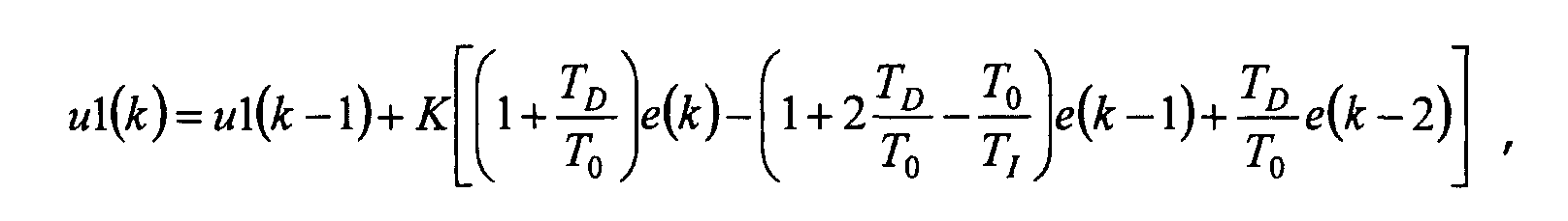
- u1(k)
- der aktueller Reglereingriff,
- u1(k-1)
- der letze Reglereingriff,
- e(k)
- die aktuelle Regelabweichung,
- e(k-1)
- die vorletzte Regelabweichung,
- K
- der Verstärkungsfaktor,
- T0
- die Abtastzeit,
- TD
- die Differenzierzeit und mit
- TI
- die Integrierzeit bezeichnet sind.
- y
- der stationäre Endwert der Sollgröße bei Regler im oberen Schaltpunkt,
- K
- der Verstärkungsfaktor,
- Tz
- die Periodendauer und
- Te
- die Einschaltdauer bezeichnet sind.
Claims (6)
- Vorrichtung zur Regelung des Kraftstoffdruckes in einem Hochdruckspeicher (7)dadurch gekennzeichnet,mit einem ersten Regler (14) für den Volumenstrom im Zufluß zu einer Hochdruckpumpe (6), die an den Hochdruckspeicher (7) angeschlossen ist,mit einem ersten Drucksensor (12), der dem Hochdruckspeicher (7) zugeordnet ist und der den Kraftstoffdruck im Hochdruckspeicher (7) dem ersten Regler (14) meldet,wobei ein zweiter Regler (17) für den Kraftstoffdruck im Hochdruckspeicher (7) vorgesehen ist, wobei der erste Drucksensor (12) den Kraftstoffdruck im Hochdruckspeicher (7) an den zweiten Regler (17) meldet,wobei der erste Regler (14) ein kontinuierliches Regelverhalten aufweist, undwobei der zweite Regler (17) ein stufenweises Regelverhalten aufweist,
daß ein Ausgang des zweiten Reglers (17) einem Eingang des ersten Reglers (14) zugeführt ist. - Vorrichtung nach Anspruch 1, dadurch gekennzeichnet,
daß für die Regelung des Volumenstromes eine regelbare Förderpumpe (20) vorgesehen ist. - Vorrichtung nach Anspruch 2, dadurch gekennzeichnet,
daß nach der regelbaren Förderpumpe (20) eine Konstantdrossel (19) angeordnet ist. - Vorrichtung nach Anspruch 1, dadurch gekennzeichnet,
daß vor der Hochdruckpumpe (6) ein zweiter Drucksensor (21) angeordnet ist, der über eine Meßleitung vorzugsweise anstelle des ersten Drucksensors (12) mit dem ersten Regler (14) verbunden ist. - Verfahren zur Regelung des Druckes in einem Hochdruckspeicher (7) für Kraftstoff, wobei dem Hochdruckspeicher (7) über eine Hochdruckpumpe (6) Kraftstoff zugeführt wird und über eine Einspritzanlage (9) Kraftstoff abgeführt wird, wobei im Niederdruckbereich vor der Hochdruckpumpe (6) der Volumenstrom des Kraftstoffes in Abhängigkeit vom Druck im Hochdruckspeicher (9) geregelt wird,dadurch gekennzeichnet,wobei im Hochdruckbereich der Druck im Hochdruckspeicher (9) in Abhängigkeit vom Druck im Hochdruckspeicher (9) geregelt wird,wobei der Volumenstrom des Kraftstoffes im Niederdruckbereich geregelt wird, wenn der Druck im Hochdruckspeicher (7) kleiner ist als ein Auslösedruck, wobei der Druck im Hochdruckspeicher (7) geregelt wird, wenn der Druck im Hochdruckspeicher (7) größer als der Auslösedruck ist, und wobei der Volumenstrom geregelt wird, wenn der Druck im Hochdruckspeicher (7) den Auslösedruck übersteigt,
daß die Volumenstromregelung in Abhängigkeit von der Druckregelung erfolgt. - Verfahren nach Anspruch 5, dadurch gekennzeichnet, daß der Auslösedruck aus einer Summe aus einem Sollwert und einem Schwellwert ermittelt wird.
Applications Claiming Priority (3)
| Application Number | Priority Date | Filing Date | Title |
|---|---|---|---|
| DE19618932 | 1996-05-10 | ||
| DE19618932A DE19618932C2 (de) | 1996-05-10 | 1996-05-10 | Vorrichtung und Verfahren zur Regelung des Kraftstoffdruckes in einem Hochdruckspeicher |
| PCT/DE1997/000902 WO1997043543A1 (de) | 1996-05-10 | 1997-05-02 | Vorrichtung und verfahren zur regelung des kraftstoffdruckes in einem hochdruckspeicher |
Publications (2)
| Publication Number | Publication Date |
|---|---|
| EP0837986A1 EP0837986A1 (de) | 1998-04-29 |
| EP0837986B1 true EP0837986B1 (de) | 2001-08-16 |
Family
ID=7793989
Family Applications (1)
| Application Number | Title | Priority Date | Filing Date |
|---|---|---|---|
| EP97924873A Expired - Lifetime EP0837986B1 (de) | 1996-05-10 | 1997-05-02 | Vorrichtung und verfahren zur regelung des kraftstoffdruckes in einem hochdruckspeicher |
Country Status (6)
| Country | Link |
|---|---|
| US (1) | US5941214A (de) |
| EP (1) | EP0837986B1 (de) |
| JP (1) | JP3731900B2 (de) |
| DE (2) | DE19618932C2 (de) |
| ES (1) | ES2162297T3 (de) |
| WO (1) | WO1997043543A1 (de) |
Cited By (3)
| Publication number | Priority date | Publication date | Assignee | Title |
|---|---|---|---|---|
| DE102008043237A1 (de) | 2008-10-28 | 2010-04-29 | Robert Bosch Gmbh | Kraftstoff-Hochdruckpumpe für eine Brennkraftmaschine |
| DE102008043217A1 (de) | 2008-10-28 | 2010-04-29 | Robert Bosch Gmbh | Kraftstoff-Hochdruckpumpe für eine Brennkraftmaschine |
| DE102010027858A1 (de) | 2010-04-16 | 2011-11-24 | Robert Bosch Gmbh | Kraftstoff-Hochdruckpumpe für eine Brennkraftmaschine |
Families Citing this family (43)
| Publication number | Priority date | Publication date | Assignee | Title |
|---|---|---|---|---|
| DE19708308C2 (de) * | 1997-02-28 | 2001-07-12 | Siemens Ag | Verfahren zur Regelung einer Regelgröße mit einem begrenzten Reglereingriff |
| DE19731994B4 (de) * | 1997-07-25 | 2007-11-15 | Robert Bosch Gmbh | Verfahren und Vorrichtung zur Steuerung einer Brennkraftmaschine |
| DE59810332D1 (de) * | 1998-01-13 | 2004-01-15 | Siemens Ag | Verfahren zur Vorgabe des Einspritzdruck-Sollwertes bei Speichereinspritzsystemen |
| DE19818421B4 (de) | 1998-04-24 | 2017-04-06 | Robert Bosch Gmbh | Kraftstoffversorgungsanlage einer Brennkraftmaschine |
| EP1000245B1 (de) * | 1998-05-26 | 2004-08-25 | Caterpillar Inc. | Hydrauliksystem mit einer pumpe mit variabler fördermenge |
| DE19838812C1 (de) * | 1998-08-26 | 2000-04-20 | Siemens Ag | Verfahren und Vorrichtung zum Einstellen eines Druckes zwischen einer Vorförderpumpe und einer Hochdruckpumpe eines Einspritzsystems |
| US6113361A (en) * | 1999-02-02 | 2000-09-05 | Stanadyne Automotive Corp. | Intensified high-pressure common-rail supply pump |
| US6694950B2 (en) * | 1999-02-17 | 2004-02-24 | Stanadyne Corporation | Hybrid control method for fuel pump using intermittent recirculation at low and high engine speeds |
| DE19933253B4 (de) * | 1999-07-15 | 2006-01-19 | Robert Bosch Gmbh | Verfahren zur Diagnose eines Kraftstoffversorgungssystems einer Brennkraftmaschine insbesondere für ein Kraftfahrzeug |
| DE19946910A1 (de) * | 1999-09-30 | 2001-04-05 | Bosch Gmbh Robert | Verfahren und Einrichtung zur Ermittlung der Kraftstofftemperatur in einem Common-Rail-System |
| DE19948170B4 (de) * | 1999-10-07 | 2005-05-04 | Kautex Textron Gmbh & Co. Kg | Kraftstoffversorgungseinrichtung sowie Kraftstoffpumpe |
| IT1320684B1 (it) | 2000-10-03 | 2003-12-10 | Fiat Ricerche | Dispositivo di controllo della portata di una pompa ad alta pressionein un impianto di iniezione a collettore comune del combustibile di un |
| DE10112163A1 (de) * | 2001-03-14 | 2002-09-19 | Bosch Gmbh Robert | Speichereinspritzsystem (Common Rail) für Brennkraftmaschinen |
| DE10131783B4 (de) * | 2001-07-03 | 2006-03-16 | Robert Bosch Gmbh | Verfahren zum Betrieb einer Brennkraftmaschine |
| DE10147189A1 (de) * | 2001-09-25 | 2003-04-24 | Bosch Gmbh Robert | Verfahren zum Betreiben eines Kraftstoffversorgungssystems für einen Verbrennungsmotor eines Kraftfahrzeugs |
| DE10242591A1 (de) * | 2002-09-13 | 2004-03-25 | Robert Bosch Gmbh | Kraftstoffeinspritzanlage für Brennkraftmaschinen |
| DE10247564A1 (de) * | 2002-10-11 | 2004-04-22 | Robert Bosch Gmbh | Verfahren zum Betreiben eines Common-Rail-Kraftstoffeinspritzsystems für Brennkraftmaschinen |
| DE10248625A1 (de) * | 2002-10-18 | 2004-04-29 | Robert Bosch Gmbh | Vorrichtung zur Drosselung der Flüssigkeitsmenge, die von einer Förderpumpe angesaugt wird |
| US20050144801A1 (en) * | 2003-12-26 | 2005-07-07 | Wilson Thomas H. | Portable battery operated floor drying apparatus |
| US7207319B2 (en) * | 2004-03-11 | 2007-04-24 | Denso Corporation | Fuel injection system having electric low-pressure pump |
| DE102004022115A1 (de) | 2004-05-05 | 2005-11-24 | Robert Bosch Gmbh | Verfahren zum Einbringen eines Reagenzmittels in einen Abgaskanal einer Brennkraftmaschine und Vorrichtung zur Durchführung des Verfahrens |
| JP2005337182A (ja) * | 2004-05-28 | 2005-12-08 | Mitsubishi Electric Corp | 内燃機関の燃圧制御装置 |
| DE102005033384B4 (de) * | 2005-07-16 | 2015-02-12 | Bayerische Motoren Werke Aktiengesellschaft | Kraftstoff-Fördereinrichtung für eine direkteinspritzende Kraftfahrzeug-Brennkraftmaschine |
| WO2007083404A1 (ja) * | 2006-01-20 | 2007-07-26 | Bosch Corporation | 内燃機関の燃料噴射システム |
| JP4605182B2 (ja) * | 2007-04-27 | 2011-01-05 | 株式会社デンソー | ポンプ制御装置およびそれを用いた燃料噴射システム |
| JP4571962B2 (ja) | 2007-08-03 | 2010-10-27 | 本田技研工業株式会社 | プラントの制御装置 |
| US20090090331A1 (en) * | 2007-10-04 | 2009-04-09 | Ford Global Technologies, Llc | Volumetric Efficiency Based Lift Pump Control |
| US8061329B2 (en) * | 2007-11-02 | 2011-11-22 | Ford Global Technologies, Llc | Lift pump control for a two pump direct injection fuel system |
| US7640916B2 (en) * | 2008-01-29 | 2010-01-05 | Ford Global Technologies, Llc | Lift pump system for a direct injection fuel system |
| DE102008021384B3 (de) | 2008-04-29 | 2009-11-26 | Continental Aktiengesellschaft | Überlagerte Druckregelung des Common-Rail-Systems |
| DE102009031527B3 (de) * | 2009-07-02 | 2010-11-18 | Mtu Friedrichshafen Gmbh | Verfahren zur Steuerung und Regelung einer Brennkraftmaschine |
| DE102009050467B4 (de) | 2009-10-23 | 2017-04-06 | Mtu Friedrichshafen Gmbh | Verfahren zur Steuerung und Regelung einer Brennkraftmaschine |
| DE102010031002B4 (de) * | 2010-07-06 | 2023-05-11 | Robert Bosch Gmbh | Verfahren zum Regeln des Drucks in einem Kraftstoff-Hochdruckspeicher einer Brennkraftmaschine |
| DE102010031622A1 (de) * | 2010-07-21 | 2012-01-26 | Robert Bosch Gmbh | Kraftstofffördereinrichung |
| KR101241594B1 (ko) | 2010-12-01 | 2013-03-11 | 기아자동차주식회사 | Gdi엔진의 연료공급시스템 및 그 제어방법 |
| DE102010062668A1 (de) * | 2010-12-08 | 2012-06-14 | Robert Bosch Gmbh | Kraftstofffördersystem einer Brennkraftmaschine, mit einer Rotationspumpe |
| DE102011004649A1 (de) * | 2011-02-24 | 2012-08-30 | Robert Bosch Gmbh | Kraftstofffördereinrichtung und Verfahren zum Betätigen einer Kraftstofffördereinrichtung |
| SE537251C2 (sv) * | 2013-05-23 | 2015-03-17 | Scania Cv Ab | Förfarande samt anordning för funktionskontroll av en högtrycksbränslepump |
| US9587578B2 (en) | 2013-12-06 | 2017-03-07 | Ford Global Technologies, Llc | Adaptive learning of duty cycle for a high pressure fuel pump |
| US9458806B2 (en) | 2014-02-25 | 2016-10-04 | Ford Global Technologies, Llc | Methods for correcting spill valve timing error of a high pressure pump |
| US9243598B2 (en) | 2014-02-25 | 2016-01-26 | Ford Global Technologies, Llc | Methods for determining fuel bulk modulus in a high-pressure pump |
| US9874185B2 (en) | 2014-05-21 | 2018-01-23 | Ford Global Technologies, Llc | Direct injection pump control for low fuel pumping volumes |
| US10563611B2 (en) * | 2014-12-19 | 2020-02-18 | Ford Global Technologies, Llc | Fuel delivery system and method for operation of a fuel delivery system |
Family Cites Families (13)
| Publication number | Priority date | Publication date | Assignee | Title |
|---|---|---|---|---|
| US3587547A (en) * | 1969-07-09 | 1971-06-28 | Ambac Ind | Fuel injection system and apparatus for use therein |
| DE3001155A1 (de) * | 1980-01-15 | 1981-07-16 | Robert Bosch Gmbh, 7000 Stuttgart | Kraftstoffeinspritzanlage fuer selbstzuendende brennkraftmaschine |
| CH674243A5 (de) * | 1987-07-08 | 1990-05-15 | Dereco Dieselmotoren Forschung | |
| JPH0343643A (ja) * | 1989-07-11 | 1991-02-25 | Toyota Autom Loom Works Ltd | 燃料噴射式エンジンの燃料供給装置 |
| JP3115099B2 (ja) * | 1992-04-13 | 2000-12-04 | 株式会社小野測器 | 燃費計測装置 |
| JP2848206B2 (ja) * | 1993-09-10 | 1999-01-20 | 三菱自動車工業株式会社 | 内燃機関用燃料供給装置 |
| DE4401083A1 (de) * | 1994-01-15 | 1995-07-20 | Daimler Benz Ag | Für eine Brennkraftmaschine vorgesehene Kraftstoffeinspritzanlage |
| DE4414242A1 (de) * | 1994-04-23 | 1995-10-26 | Bosch Gmbh Robert | Kraftstoffeinspritzeinrichtung für Brennkraftmaschinen |
| DE4445586A1 (de) * | 1994-12-20 | 1996-06-27 | Bosch Gmbh Robert | Verfahren zur Reduzierung des Kraftstoffdruckes in einer Kraftstoffeinspritzeinrichtung |
| IT1281303B1 (it) * | 1995-03-28 | 1998-02-17 | Elasis Sistema Ricerca Fiat | Dispositivo di regolazione della pressione di alimentazione di un fluido in un accumulatore di fluido in pressione, ad esempio per |
| ES2135815T3 (es) * | 1995-05-03 | 1999-11-01 | Daimler Chrysler Ag | Tobera de inyeccion. |
| DE19548278B4 (de) * | 1995-12-22 | 2007-09-13 | Robert Bosch Gmbh | Verfahren und Vorrichtung zur Steuerung einer Brennkraftmaschine |
| DE19607070B4 (de) * | 1996-02-24 | 2013-04-25 | Robert Bosch Gmbh | Verfahren und Vorrichtung zur Steuerung einer Brennkraftmaschine |
-
1996
- 1996-05-10 DE DE19618932A patent/DE19618932C2/de not_active Expired - Fee Related
-
1997
- 1997-05-02 DE DE59704282T patent/DE59704282D1/de not_active Expired - Lifetime
- 1997-05-02 WO PCT/DE1997/000902 patent/WO1997043543A1/de not_active Ceased
- 1997-05-02 EP EP97924873A patent/EP0837986B1/de not_active Expired - Lifetime
- 1997-05-02 ES ES97924873T patent/ES2162297T3/es not_active Expired - Lifetime
- 1997-05-02 JP JP54038197A patent/JP3731900B2/ja not_active Expired - Fee Related
-
1998
- 1998-01-12 US US09/005,699 patent/US5941214A/en not_active Expired - Lifetime
Cited By (4)
| Publication number | Priority date | Publication date | Assignee | Title |
|---|---|---|---|---|
| DE102008043237A1 (de) | 2008-10-28 | 2010-04-29 | Robert Bosch Gmbh | Kraftstoff-Hochdruckpumpe für eine Brennkraftmaschine |
| DE102008043217A1 (de) | 2008-10-28 | 2010-04-29 | Robert Bosch Gmbh | Kraftstoff-Hochdruckpumpe für eine Brennkraftmaschine |
| WO2010049207A1 (de) | 2008-10-28 | 2010-05-06 | Robert Bosch Gmbh | Kraftstoff-hochdruckpumpe für eine brennkraftmaschine |
| DE102010027858A1 (de) | 2010-04-16 | 2011-11-24 | Robert Bosch Gmbh | Kraftstoff-Hochdruckpumpe für eine Brennkraftmaschine |
Also Published As
| Publication number | Publication date |
|---|---|
| WO1997043543A1 (de) | 1997-11-20 |
| DE59704282D1 (de) | 2001-09-20 |
| JPH11509605A (ja) | 1999-08-24 |
| DE19618932C2 (de) | 2001-02-01 |
| JP3731900B2 (ja) | 2006-01-05 |
| US5941214A (en) | 1999-08-24 |
| DE19618932A1 (de) | 1997-11-20 |
| EP0837986A1 (de) | 1998-04-29 |
| ES2162297T3 (es) | 2001-12-16 |
Similar Documents
| Publication | Publication Date | Title |
|---|---|---|
| EP0837986B1 (de) | Vorrichtung und verfahren zur regelung des kraftstoffdruckes in einem hochdruckspeicher | |
| DE19548278B4 (de) | Verfahren und Vorrichtung zur Steuerung einer Brennkraftmaschine | |
| DE10162989C1 (de) | Schaltungsanordnung zum Regeln einer regelbaren Kraftstoffpumpe, Verfahren zum Regeln einer Förderleistung und Verfahren zum Überprüfen der Funktionsfähigkeit einer regelbaren Kraftstoffpumpe | |
| EP1303693B1 (de) | Verfahren und vorrichtung zur steuerung einer brennkraftmaschine | |
| DE102008021384B3 (de) | Überlagerte Druckregelung des Common-Rail-Systems | |
| DE19731994B4 (de) | Verfahren und Vorrichtung zur Steuerung einer Brennkraftmaschine | |
| DE19752025B4 (de) | Verfahren und Vorrichtung zum Regeln des Kraftstoffdruckes in einem Kraftstoffspeicher | |
| EP0930426B1 (de) | Verfahren zur Vorgabe des Einspritzdruck-Sollwertes bei Speichereinspritzsystemen | |
| EP2006521A1 (de) | Verfahren zur Regelung des Raildrucks während eines Startvorgangs | |
| DE19731995A1 (de) | Verfahren und Vorrichtung zur Steuerung einer Brennkraftmaschine | |
| WO2010052119A1 (de) | Verfahren und vorrichtung zum betreiben einer einspritzanlage für eine brennkraftmaschine | |
| DE4443879B4 (de) | Einrichtung und Verfahren zur Kraftstoffversorgung bei einer Brennkraftmaschine | |
| DE19731201C2 (de) | Verfahren zum Regeln des Kraftstoffdruckes in einem Kraftstoffspeicher | |
| DE102007015876A1 (de) | Verfahren zur Erkennung einer Fehlfunktion eines Raildrucksensors | |
| WO2020165333A1 (de) | Verfahren zum betreiben eines einspritzsystems einer brennkraftmaschine, einspritzsystem für eine brennkraftmaschine sowie brennkraftmaschine mit einem solchen einspritzsystem | |
| EP0185183A2 (de) | Elektronisch gesteuertes Kraftstoffeinspritzsystem für eine Brennkraftmaschine | |
| EP1266134A1 (de) | Verfahren zum betreiben einer brennkraftmaschine | |
| EP1403494B1 (de) | Verfahren und Vorrichtung zur Regelung einer Druckgrösse einer Brennkraftmaschine | |
| EP1802859A1 (de) | Verfahren zum betreiben einer kraftstoffeinspritzanlage insbesondere eines kraftfahrzeugs | |
| DE69415140T2 (de) | STEUERSYSTEM FüR EIN HOCHDRUCK-KRAFTSTOFFEINSPRITZSYSTEM FüR EINE BRENNKRAFTMASCHINE | |
| DE19917711A1 (de) | Verfahren und Vorrichtung zur Steuerung einer Brennkraftmaschine | |
| DE19735938A1 (de) | Verfahren und Vorrichtung zur Steuerung einer Brennkraftmaschine | |
| DE19946908A1 (de) | Verfahren zum Abbau des Rail-Drucks in einem Common-Rail-System für Brennkraftmaschinen | |
| DE102013000060B3 (de) | Verfahren und Regeleinrichtung zum Betreiben einer Brennkraftmaschine | |
| EP1672206B1 (de) | Verfahren und Vorrichtung zur Motorsteuerung bei einem Kraftfahrzeug |
Legal Events
| Date | Code | Title | Description |
|---|---|---|---|
| PUAI | Public reference made under article 153(3) epc to a published international application that has entered the european phase |
Free format text: ORIGINAL CODE: 0009012 |
|
| 17P | Request for examination filed |
Effective date: 19980107 |
|
| AK | Designated contracting states |
Kind code of ref document: A1 Designated state(s): DE ES FR GB IT |
|
| 17Q | First examination report despatched |
Effective date: 19991123 |
|
| GRAG | Despatch of communication of intention to grant |
Free format text: ORIGINAL CODE: EPIDOS AGRA |
|
| GRAG | Despatch of communication of intention to grant |
Free format text: ORIGINAL CODE: EPIDOS AGRA |
|
| GRAH | Despatch of communication of intention to grant a patent |
Free format text: ORIGINAL CODE: EPIDOS IGRA |
|
| GRAH | Despatch of communication of intention to grant a patent |
Free format text: ORIGINAL CODE: EPIDOS IGRA |
|
| GRAA | (expected) grant |
Free format text: ORIGINAL CODE: 0009210 |
|
| AK | Designated contracting states |
Kind code of ref document: B1 Designated state(s): DE ES FR GB IT |
|
| REF | Corresponds to: |
Ref document number: 59704282 Country of ref document: DE Date of ref document: 20010920 |
|
| GBT | Gb: translation of ep patent filed (gb section 77(6)(a)/1977) |
Effective date: 20011116 |
|
| REG | Reference to a national code |
Ref country code: ES Ref legal event code: FG2A Ref document number: 2162297 Country of ref document: ES Kind code of ref document: T3 |
|
| REG | Reference to a national code |
Ref country code: GB Ref legal event code: IF02 |
|
| ET | Fr: translation filed | ||
| PLBE | No opposition filed within time limit |
Free format text: ORIGINAL CODE: 0009261 |
|
| STAA | Information on the status of an ep patent application or granted ep patent |
Free format text: STATUS: NO OPPOSITION FILED WITHIN TIME LIMIT |
|
| 26N | No opposition filed | ||
| PGFP | Annual fee paid to national office [announced via postgrant information from national office to epo] |
Ref country code: IT Payment date: 20060531 Year of fee payment: 10 |
|
| PGFP | Annual fee paid to national office [announced via postgrant information from national office to epo] |
Ref country code: ES Payment date: 20060619 Year of fee payment: 10 |
|
| REG | Reference to a national code |
Ref country code: ES Ref legal event code: FD2A Effective date: 20070503 |
|
| PG25 | Lapsed in a contracting state [announced via postgrant information from national office to epo] |
Ref country code: ES Free format text: LAPSE BECAUSE OF NON-PAYMENT OF DUE FEES Effective date: 20070503 |
|
| PGFP | Annual fee paid to national office [announced via postgrant information from national office to epo] |
Ref country code: FR Payment date: 20090513 Year of fee payment: 13 |
|
| PG25 | Lapsed in a contracting state [announced via postgrant information from national office to epo] |
Ref country code: IT Free format text: LAPSE BECAUSE OF NON-PAYMENT OF DUE FEES Effective date: 20070502 |
|
| PGFP | Annual fee paid to national office [announced via postgrant information from national office to epo] |
Ref country code: GB Payment date: 20090522 Year of fee payment: 13 |
|
| GBPC | Gb: european patent ceased through non-payment of renewal fee |
Effective date: 20100502 |
|
| REG | Reference to a national code |
Ref country code: FR Ref legal event code: ST Effective date: 20110131 |
|
| PG25 | Lapsed in a contracting state [announced via postgrant information from national office to epo] |
Ref country code: FR Free format text: LAPSE BECAUSE OF NON-PAYMENT OF DUE FEES Effective date: 20100531 |
|
| PG25 | Lapsed in a contracting state [announced via postgrant information from national office to epo] |
Ref country code: GB Free format text: LAPSE BECAUSE OF NON-PAYMENT OF DUE FEES Effective date: 20100502 |
|
| REG | Reference to a national code |
Ref country code: DE Ref legal event code: R081 Ref document number: 59704282 Country of ref document: DE Owner name: KLUEGL, WENDELIN, DE Free format text: FORMER OWNER: CONTINENTAL AUTOMOTIVE GMBH, 30165 HANNOVER, DE |
|
| PGFP | Annual fee paid to national office [announced via postgrant information from national office to epo] |
Ref country code: DE Payment date: 20160725 Year of fee payment: 20 |
|
| REG | Reference to a national code |
Ref country code: DE Ref legal event code: R071 Ref document number: 59704282 Country of ref document: DE |