EP0836070B1 - Véhicule blindé - Google Patents
Véhicule blindé Download PDFInfo
- Publication number
- EP0836070B1 EP0836070B1 EP97117300A EP97117300A EP0836070B1 EP 0836070 B1 EP0836070 B1 EP 0836070B1 EP 97117300 A EP97117300 A EP 97117300A EP 97117300 A EP97117300 A EP 97117300A EP 0836070 B1 EP0836070 B1 EP 0836070B1
- Authority
- EP
- European Patent Office
- Prior art keywords
- vehicle according
- viewing hood
- armoured vehicle
- viewing
- hood
- Prior art date
- Legal status (The legal status is an assumption and is not a legal conclusion. Google has not performed a legal analysis and makes no representation as to the accuracy of the status listed.)
- Expired - Lifetime
Links
- 230000004438 eyesight Effects 0.000 claims description 22
- 208000010415 Low Vision Diseases 0.000 claims description 4
- 230000004303 low vision Effects 0.000 claims description 4
- 239000011521 glass Substances 0.000 claims description 3
- 238000005406 washing Methods 0.000 claims description 2
- 238000010304 firing Methods 0.000 claims 1
- 230000001681 protective effect Effects 0.000 description 4
- 238000010276 construction Methods 0.000 description 2
- 230000004297 night vision Effects 0.000 description 2
- 230000002093 peripheral effect Effects 0.000 description 2
- 230000006978 adaptation Effects 0.000 description 1
- 230000005540 biological transmission Effects 0.000 description 1
- 230000006735 deficit Effects 0.000 description 1
- 230000002349 favourable effect Effects 0.000 description 1
- 230000001771 impaired effect Effects 0.000 description 1
- 230000010354 integration Effects 0.000 description 1
- 239000000779 smoke Substances 0.000 description 1
- 230000008685 targeting Effects 0.000 description 1
- 238000001931 thermography Methods 0.000 description 1
Images
Classifications
-
- F—MECHANICAL ENGINEERING; LIGHTING; HEATING; WEAPONS; BLASTING
- F41—WEAPONS
- F41H—ARMOUR; ARMOURED TURRETS; ARMOURED OR ARMED VEHICLES; MEANS OF ATTACK OR DEFENCE, e.g. CAMOUFLAGE, IN GENERAL
- F41H5/00—Armour; Armour plates
- F41H5/26—Peepholes; Windows; Loopholes
Definitions
- the invention relates to an armored vehicle according to the specified in the preamble of claim 1 Art.
- Armored vehicles are for different areas of application especially with the police and the Bundesvid known and must on the one hand for participation at least a direct view on the road for an occupant, especially for the driver, enable. On the other hand, protection and for technical reasons, an indirect view is required about the danger to the driver to keep it as low as possible.
- the driver of the known vehicle gets a direct view armored vehicle by placing it on a chair sitting within easy reach of the controls for control of the vehicle from a lockable by a hatch Entry opening in the housing ceiling of the tub housing of the armored vehicle looks out with his head.
- For driving the vehicle are partial additional controls and instruments in the area the entrance opening.
- the known armored vehicle has the disadvantage that the construction for setting up the direct and indirect view very expensive for the driver is.
- For the adjustment of the driver's seat from the direct View position in the indirect view position and vice versa is an elaborate design of both Seat, the pedal mechanism and the other controls necessary as this for a flawless Guidance of the vehicle also adjusted by the driver need to be as predetermined as possible To keep distance from the driver.
- the adjustment range the seat, the pedal mechanism and the others Controls such as steering wheel and dashboard must hence the two seating positions for direct and indirect View as well as the driver percentile range, d. H. the adjustment range which is used for adjustment in the respective seating position to the different Sizes of the respective driver is required.
- the protective hood carried in or on the vehicle Space takes up, causing the payload of more Instruments and devices restricted becomes.
- a generic armored vehicle is from the DE-PS 736 470 known that having a slit Tower is provided.
- the eye slits can be made by lifting or lowering one adjustable hood opened, enlarged or closed become. In battle conditions, the viewing slits are closed and the view outside is via Angle mirror. By lifting and lowering the hood takes up a lot of space, so for example the arrangement a cannon is restricted by this.
- GB-A-2 285 498 describes a sighting device for a swiveling one in azimuth Tower of a combat vehicle described entirely as opto-electrical Sighting device is formed.
- an opto-electrical sensor on the tower,
- a thermal imaging sensor arranged opposite the tower is rotatable in azimuth and the image processing units on both in Tower and viewing devices arranged in the vehicle tub are connected is. There are no direct views from the tower.
- the invention has for its object an armored Vehicle according to the preamble of the claim 1 specified type in such a way that a simple while avoiding the disadvantages mentioned and quick change from direct to indirect View for an occupant and vice versa is made possible without endangering the occupant (s).
- This task is characterized by the characteristics of claim 1 in connection with its preamble features solved.
- the invention is based on the finding that through Integration of funds that are direct and indirect View of a vehicle occupant of the armored vehicle allow in a rotatable with the casing of the armored Vehicle permanently attached hood, the Eye level of the occupant can remain constant and thus the driver's seat and the controls when changing no longer blocked between direct and indirect view Need to become. Therefore the adjustment range the seat for the occupant and that assigned to him Control elements significantly reduced and thus the technical Decisive effort for the adjustment range be reduced. There is also a faster change possible between direct and indirect view, without that the vehicle guidance is impaired.
- the viewing hood with the vehicle rotatably connected and on the circumference of the viewing hood are at least in some areas means for the direct and indirect vision provided by turning the viewing hood in predetermined positions for the direct view or indirect view of the field of vision of the occupant can be brought.
- the viewing hood is essentially rotationally symmetrical trained and partially with their peripheral surface in the protected profile area of the housing arranged of the vehicle. So that's for example means of direct vision when not in use through part of the armored vehicle body shielded and thus protected from projectiles.
- the viewing hood is designed so that it is open at the bottom at least the head of an occupant, especially the Driver, for a direct view from the vehicle can be inserted into the viewing hood.
- the viewing hood preferably has a hatch lockable entry opening so that a simple Guaranteed getting in and out of the occupant is.
- the means enabling the indirect view is preferred through at least one angle mirror and that means enabling direct vision by at least a recess is formed in the circumference of the viewing hood.
- the Angle mirror also has an associated one Recess in the scope of the viewing hood and is preferred bulletproof.
- the recess which enables the direct view comprises according to a further embodiment of the invention transparent lens made of bulletproof glass can be.
- a windshield wiper and washer for the viewing window in the recess of the hood can if necessary be provided.
- a target device for example a laser aiming light for a sight hood be mounted remotely mounted weapon.
- the viewing hood is preferably continuous pivoted in the vehicle housing.
- At least one section in the circumference of the viewing hood Launching device for example a throwing cup for Grenades, a fog launcher or a firearm.
- a throwing cup for Grenades for example a throwing cup for Grenades, a fog launcher or a firearm.
- launchers for easy use of such launchers to enable these are from the inside the viewing hood by the driver or a reloadable to other occupants.
- a quick change can be made using a hand crank Gearbox and / or a motor drive reached become.
- a motor drive is particularly useful with an armored and therefore heavy hood on.
- the motor drive with a control device a weapon coupled to the hood.
- a weapon coupled to the hood.
- a crosshair as Target device on average for direct and / or indirect view.
- the field of vision in the direct view can be determined by a Low-vision aid, for example through the upper and lower Deflection mirror arranged in the region of the recess to be expanded in such a way that both those created by the Vehicle housing and / or the hood caused by dead Field of vision for the driver reduced as well an upright image of the extended field of vision is achieved.
- a Low-vision aid for example through the upper and lower Deflection mirror arranged in the region of the recess to be expanded in such a way that both those created by the Vehicle housing and / or the hood caused by dead Field of vision for the driver reduced as well an upright image of the extended field of vision is achieved.
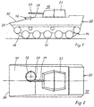
- FIG. 1 to 5 is an embodiment of a armored vehicle 10 with a rotatable, fixed with the viewing hood 12 connected to the vehicle 10.
- the main battle tank 10 includes a chain drive 14 several sprockets 16 and a chain 18, one Vehicle housing 20 and one over the vehicle housing 20 tower 22 with a cannon 24.
- the rear area 28 of the viewing hood engages 12 in the protected profile area of the housing of the vehicle 10.
- the dimensioning of the sloping front Ceiling 30 of the vehicle housing 20 and the arrangement the viewing hood 12 in the vehicle housing 20 are so matched that essentially the rear area the peripheral surface of the hood 12 through the vehicle housing 20 is shielded.
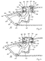
- the rotating ring 32 firmly connected to the viewing hood 12 is via an electric motor 34 and an electric motor 34 and rotary ring 32 intermediate gear 36 driven and can thereby in predetermined Positions can be adjusted.
- a Handle 38 connected to the rotating ring 32. So that can the rotation adjustment of the viewing hood 12 by a vehicle driver 40 manually in the predetermined positions respectively.
- an elbow can be arranged be of sufficient pivotability of the Viewing hood 12 guaranteed over a range of ⁇ 180 °.
- the handle 38 is only for reasons of clarity shown in Figure 4.
- a recess 42 is made in the periphery of the viewing hood 12, the one front window 44 and one side side windows 46 and 48 arranged for this purpose.
- the front window 44 and the two side windows 46 and 48 are connected by the viewing hood 12 as well as on the adjacent surfaces armored glasses firmly connected to one another.
- the front angle mirror is in the direction of travel of the vehicle 50 and laterally a side angle mirror 52 and 54 arranged.
- the driver receives thereby not only a bulletproof look in Vehicle direction, but also to the side.
- FIG. 3 thus shows the viewing hood 12 in the position, in which the direct view of the driver 40 through windows 44 to 48, for example for a cruise
- Figure 4 shows the predetermined position of the viewing hood 12, in which the driver 40 has an indirect View through the angle mirror 52 to 54, for example for combat driving.
- the viewing hood 12 has an entry opening 58 provided, which can be closed by a hatch 60.
- the open entrance opening 58 shows Figure 3 and the closed figure 4.
- a driver seat 62 Below the hood 12 is a driver seat 62 and the controls for driving the vehicle, such as a Pedal mechanism 64, a steering wheel 66 and a dashboard 68, arranged in a known manner.
- the adjustment range of the Driver's seat 62 and the controls 64 to 68 is on the adaptation to the height of the driver 40 designed.
- the Viewing hood 12 Via a spring-loaded in the direction of the rotating ring 32 Locking pin 70 and the locking pin 70 assigned, , not shown, holes in the rotating ring 32, the Viewing hood 12 in predetermined positions, such as Position for direct or indirect Point of view, be fixed. This will emigrate the field of vision of the driver 40, in particular at Off-road driving, prevented.
- the locking pin 70 can if necessary by a hook in its non-locking Position are secured so that tracking, d. H. continuous rotation of the viewing hood 12 is guaranteed.
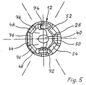
- FIG 5 is a section in plan view of the viewing hood 12 shown. From this it can be seen that in scope the viewing hood 12 between the side angle mirror 54 and the side window 48 a night vision device 72 and between the side angle mirror 52 and the side window 46 a launcher 74 for smoke grenades is provided.
- a target device for example a laser target light
- Another target device can be found in Shape of a crosshair in the front angle mirror 50 be provided, in which case the electric motor 34 with the Control device of the cannon 24 is coupled. Bring the driver 40 now crosshairs with the Target in cover, the cannon 24 will accordingly the goal aligned.
- Such control circuits are generally known and will therefore not be discussed in more detail described.
- the viewing hood 12 is armored.
- a low-vision aid in the form two attached mirrors 76 attached. This will the dead zone of vision caused by the vehicle housing 20 the possible field of vision for the driver 40 downsized, as well as an upright Image of the extended field of view achieved.
- the invention is characterized in that it Driver 40 guaranteed weather and hazard protection. Granted for journeys with an indirect view the viewing hood 12 has the same armor protection as that Vehicle housing 20 of the main battle tank 10. The View of the display of the devices in all operating states enabled without interference. Additional ads are not required.
- the driver's eye point 40 relative to vehicle 10 remains constant, so that the adjustment range of the driver's seat 62 of the pedal mechanism 64 and possibly the steering wheel 66 with the Dashboard 68 on the driver percentile range to be covered limited.
- a change in the various operating states of the Viewing hood 12 is quick and easy without impairment the operation of the main battle tank 10 possible.
- the Invention can of course also be used in armored vehicles Wheel drive vehicles used without further ado become.
Landscapes
- Engineering & Computer Science (AREA)
- General Engineering & Computer Science (AREA)
- Aiming, Guidance, Guns With A Light Source, Armor, Camouflage, And Targets (AREA)
Claims (20)
- Véhicule blindé (10) comportant une calotte de visibilité (12) qui permet une visibilité indirecte et directe hors du véhicule (10), caractérisé en ce que la calotte de visibilité (12) est reliée solidaire en rotation avec le véhicule (10) et en ce qu'il est prévu à la périphérie de la calotte de visibilité (12), au moins sur certaines zones, d'une part des moyens (42, 44, 46, 48) pour la visibilité directe et d'autre part des moyens (50, 52, 54, 56) pour la visibilité indirecte qui, par la rotation de la calotte de visibilité (12) dans des positions déterminées, peuvent être amenés dans le champ visuel de l'occupant (40) pour la visibilité directe ou pour la visibilité indirecte.
- Véhicule blindé selon la revendication 1, caractérisé en ce que la calotte de visibilité (12) est réalisée sensiblement à symétrie de révolution et est agencée partiellement avec sa surface périphérique dans la zone de profil protégée de la carrosserie (20) du véhicule (10) de telle sorte que la surface périphérique est protégée sur certaines zones.
- Véhicule blindé selon l'une ou l'autre des revendications 1 et 2, caractérisé en ce que la calotte de visibilité (12) présente une ouverture d'accès (58) susceptible d'être fermée par un hublot (60).
- Véhicule blindé selon l'une quelconque des revendications précédentes, caractérisé en ce que la calotte de visibilité (12) peut être bloquée dans les positions prédéterminées.
- Véhicule blindé selon l'une quelconque des revendications précédentes, caractérisé en ce que les moyens permettant la visibilité indirecte sont formés par au moins un épiscope (50 à 54).
- Véhicule blindé selon la revendication 5, caractérisé par un épiscope (50 à 54) à l'épreuve des projectiles.
- Véhicule blindé selon l'une quelconque des revendications précédentes, caractérisé en ce que le moyen permettant la visibilité directe est formé par au moins un évidement (42) dans la périphérie de la calotte de visibilité (12).
- Véhicule blindé selon la revendication 7, caractérisé en ce que l'évidement (42) comprend une vitre de visibilité (44 à 48) transparente.
- Véhicule blindé selon la revendication 8, caractérisé par une vitre de visibilité (44 à 48) en verre blindé.
- Véhicule blindé selon l'une ou l'autre des revendications 8 et 9, caractérisé par un dispositif d'essuie-glace et de lave-glace pour la vitre de visibilité (44 à 48).
- Véhicule blindé selon l'une quelconque des revendications précédentes, caractérisé en ce que dans au moins un tronçon de la périphérie de la calotte de visibilité (12) est agencé un dispositif de visée, par exemple un viseur à lumière laser pour une arme (24) montée en décalage par rapport à la calotte de visibilité.
- Véhicule blindé selon l'une quelconque des revendications précédentes, en particulier selon la revendication 11, caractérisé en ce que la calotte de visibilité (12), en particulier pour la poursuite d'une cible, est montée en pivotement continu sur la carrosserie de véhicule (20).
- Véhicule blindé selon l'une quelconque des revendications précédentes, caractérisé en ce que dans au moins un tronçon dans la périphérie de la calotte de visibilité (12) est agencé un dispositif de tir (74).
- Véhicule blindé selon l'une quelconque des revendications précédentes, caractérisé en ce que dans au moins un tronçon dans la périphérie de la calotte de visibilité (12) sont agencés des moyens d'amplification d'image (72).
- Véhicule blindé selon l'une quelconque des revendications précédentes, caractérisé par un entraínement motorisé (34, 36) de la calotte de visibilité (12).
- Véhicule blindé selon la revendication 15, caractérisé en ce que l'entraínement motorisé (34, 36) est accouplé à un dispositif de commande d'une arme (24) montée en décalage par rapport à la calotte de visibilité (12).
- Véhicule blindé selon l'une quelconque des revendications précédentes, caractérisé en ce que la calotte de visibilité (12) est montée dans la carrosserie de véhicule (20) par l'intermédiaire d'une bague rotative (32).
- Véhicule blindé selon l'une quelconque des revendications 1 à 16, caractérisé en ce que la calotte de visibilité (12) est montée dans la carrosserie de véhicule (20) par l'intermédiaire d'un arc de rotation.
- Véhicule blindé selon l'une quelconque des revendications 7 à 18, caractérisé en ce que dans la partie supérieure et dans la partie inférieure de l'évidement (42) est agencée une aide à la visibilité basse, par exemple des rétroviseurs (76) de sorte qu'on réduit la zone de visibilité morte pour le conducteur de véhicule 40 et on obtient une reproduction redressée de la zone de visibilité agrandie.
- Véhicule blindé selon l'une quelconque des revendications précédentes, caractérisé par une calotte de visibilité (12) blindée.
Applications Claiming Priority (2)
| Application Number | Priority Date | Filing Date | Title |
|---|---|---|---|
| DE19642386 | 1996-10-14 | ||
| DE19642386A DE19642386C1 (de) | 1996-10-14 | 1996-10-14 | Gepanzertes Fahrzeug |
Publications (2)
| Publication Number | Publication Date |
|---|---|
| EP0836070A1 EP0836070A1 (fr) | 1998-04-15 |
| EP0836070B1 true EP0836070B1 (fr) | 2001-12-05 |
Family
ID=7808735
Family Applications (1)
| Application Number | Title | Priority Date | Filing Date |
|---|---|---|---|
| EP97117300A Expired - Lifetime EP0836070B1 (fr) | 1996-10-14 | 1997-10-07 | Véhicule blindé |
Country Status (2)
| Country | Link |
|---|---|
| EP (1) | EP0836070B1 (fr) |
| DE (2) | DE19642386C1 (fr) |
Families Citing this family (6)
| Publication number | Priority date | Publication date | Assignee | Title |
|---|---|---|---|---|
| DE19912557A1 (de) * | 1999-03-19 | 2000-09-21 | Krauss Maffei Wegmann Gmbh & C | Luke für gepanzerte Fahrzeuge |
| EP1059504A3 (fr) * | 1999-06-10 | 2002-01-30 | Technology Investments Limited | Dispositif d'observation pour véhicule |
| DE102005024404A1 (de) * | 2005-05-27 | 2006-12-07 | Krauss-Maffei Wegmann Gmbh & Co. Kg | Einrichtung zur mechanisch gekoppelten Verstellung von Lukendeckel und Fahrersitz an einem gepanzerten Fahrzeug |
| DE102006010586B4 (de) * | 2006-03-06 | 2013-03-21 | Rheinmetall Landsysteme Gmbh | Anzeige- und Bediensystem |
| DE102006062262B4 (de) * | 2006-12-22 | 2010-06-02 | Diehl Bgt Defence Gmbh & Co. Kg | Winkelspiegelvorrichtung |
| DE102008034245B4 (de) * | 2008-07-23 | 2012-05-24 | Krauss-Maffei Wegmann Gmbh & Co. Kg | Lukendeckel zur Verwendung an einem gepanzerten Fahrzeug, insbesondere Kampffahrzeug |
Family Cites Families (7)
| Publication number | Priority date | Publication date | Assignee | Title |
|---|---|---|---|---|
| DE736470C (de) * | 1938-02-06 | 1943-06-18 | Carl F W Borgward | Panzerturm fuer Panzerwagen, Tanks o. dgl. |
| US2454268A (en) * | 1945-04-11 | 1948-11-23 | Frederick S Brackett | Periscope mounting for armored vehicles |
| US4499490A (en) * | 1982-05-10 | 1985-02-12 | Morgan Jack B | Scanning apparatus with video camera |
| GB2285498B (en) * | 1987-07-15 | 1996-03-20 | Barr & Stroud Ltd | Turret viewing device |
| FR2629579B1 (fr) * | 1988-03-31 | 1991-01-18 | Durand Jean | Perfectionnements aux dispositifs d'observation pour engins militaires |
| DE19506583C1 (de) * | 1995-02-24 | 1996-04-04 | Daimler Benz Ag | Temporärer durchsichtiger Wetterschutz für eine Fahrer-Ausblicks-Luke eines gepanzerten Fahrzeuges |
| FR2739192B1 (fr) * | 1995-09-22 | 1997-10-24 | Thomson Csf | Dispositif de veille panoramique optronique a grande vitesse |
-
1996
- 1996-10-14 DE DE19642386A patent/DE19642386C1/de not_active Expired - Fee Related
-
1997
- 1997-10-07 DE DE59705653T patent/DE59705653D1/de not_active Expired - Lifetime
- 1997-10-07 EP EP97117300A patent/EP0836070B1/fr not_active Expired - Lifetime
Also Published As
| Publication number | Publication date |
|---|---|
| DE19642386C1 (de) | 1998-01-29 |
| DE59705653D1 (de) | 2002-01-17 |
| EP0836070A1 (fr) | 1998-04-15 |
Similar Documents
| Publication | Publication Date | Title |
|---|---|---|
| EP1061323B2 (fr) | Véhicule blindé pour le transport de soldats | |
| DE102010016560C5 (de) | Fahrzeug, insbesondere militärisches Kampffahrzeug | |
| WO2003087701A2 (fr) | Vehicule de combat, en particulier vehicule blinde de combat d'infanterie | |
| DE4338650C1 (de) | Nebelwurfanlage eines gepanzerten Fahrzeuges | |
| EP0388762B1 (fr) | Module d'armes pour chars de bataille | |
| EP0836070B1 (fr) | Véhicule blindé | |
| EP0611942B1 (fr) | Affût d'arme pour véhicule blindé | |
| DE3515820A1 (de) | Lukenabdeckung fuer ein panzerfahrzeug | |
| EP1191303B1 (fr) | Véhicule blindé, en particulier véhicule de combat | |
| EP0899533B1 (fr) | Affût orientable | |
| DE1428746A1 (de) | Kampffahrzeug | |
| EP0011856B1 (fr) | Dispositif pour verrouiller un affût d'arme monté pivotant autour d'un axe horizontal et avec lequel une arme, p.ex. un canon à cadence de tir élevée, peut être orientée en site | |
| DE10247350A1 (de) | Einrichtung zum Schutz von Objekten gegen als Lenk-Flugkörper ausgebildete Munitionen | |
| EP3803253B1 (fr) | Dispositif de système auxiliaire pour un véhicule | |
| DE3606192C2 (de) | Visiervorrichtung für Panzerfahrzeug | |
| DE102022107733A1 (de) | Militärisches Fahrzeug | |
| DE3119621C2 (fr) | ||
| EP0072958B1 (fr) | Equipement optique pour véhicules blindés | |
| DE3108132A1 (de) | Lafette, insbesondere fuer gepanzerte objekte, z.b. fuer panzerfahrzeuge, zum aufnehmen von handfeuerwaffen | |
| DE4307160A1 (de) | Gepanzertes Kampffahrzeug, insbesondere Kampfpanzer | |
| DE3437625C2 (fr) | ||
| DE3508660C2 (de) | Kampffahrzeug mit scheitellafettierter Waffenanlage | |
| DE2406099A1 (de) | Militaerische einrichtung | |
| DE102006045991A1 (de) | Geschützte Infanteriekabine bevorzugt für den Häuserkampf insbesondere in urbanen Gebieten | |
| DE1196098B (de) | Halterung fuer leichte Waffen mit einem Zielfernrohr |
Legal Events
| Date | Code | Title | Description |
|---|---|---|---|
| PUAI | Public reference made under article 153(3) epc to a published international application that has entered the european phase |
Free format text: ORIGINAL CODE: 0009012 |
|
| AK | Designated contracting states |
Kind code of ref document: A1 Designated state(s): DE FR GB |
|
| 17P | Request for examination filed |
Effective date: 19981015 |
|
| AKX | Designation fees paid |
Free format text: DE FR GB |
|
| RBV | Designated contracting states (corrected) |
Designated state(s): DE FR GB |
|
| RAP1 | Party data changed (applicant data changed or rights of an application transferred) |
Owner name: KRAUSS-MAFFEI WEGMANN GMBH & CO. KG |
|
| 17Q | First examination report despatched |
Effective date: 20000127 |
|
| GRAG | Despatch of communication of intention to grant |
Free format text: ORIGINAL CODE: EPIDOS AGRA |
|
| GRAG | Despatch of communication of intention to grant |
Free format text: ORIGINAL CODE: EPIDOS AGRA |
|
| GRAG | Despatch of communication of intention to grant |
Free format text: ORIGINAL CODE: EPIDOS AGRA |
|
| GRAH | Despatch of communication of intention to grant a patent |
Free format text: ORIGINAL CODE: EPIDOS IGRA |
|
| GRAH | Despatch of communication of intention to grant a patent |
Free format text: ORIGINAL CODE: EPIDOS IGRA |
|
| GRAA | (expected) grant |
Free format text: ORIGINAL CODE: 0009210 |
|
| AK | Designated contracting states |
Kind code of ref document: B1 Designated state(s): DE FR GB |
|
| REG | Reference to a national code |
Ref country code: GB Ref legal event code: IF02 |
|
| REF | Corresponds to: |
Ref document number: 59705653 Country of ref document: DE Date of ref document: 20020117 |
|
| GBT | Gb: translation of ep patent filed (gb section 77(6)(a)/1977) |
Effective date: 20020131 |
|
| ET | Fr: translation filed | ||
| PLBE | No opposition filed within time limit |
Free format text: ORIGINAL CODE: 0009261 |
|
| STAA | Information on the status of an ep patent application or granted ep patent |
Free format text: STATUS: NO OPPOSITION FILED WITHIN TIME LIMIT |
|
| 26N | No opposition filed | ||
| REG | Reference to a national code |
Ref country code: FR Ref legal event code: PLFP Year of fee payment: 19 |
|
| PGFP | Annual fee paid to national office [announced via postgrant information from national office to epo] |
Ref country code: DE Payment date: 20151031 Year of fee payment: 19 Ref country code: GB Payment date: 20151026 Year of fee payment: 19 |
|
| PGFP | Annual fee paid to national office [announced via postgrant information from national office to epo] |
Ref country code: FR Payment date: 20151026 Year of fee payment: 19 |
|
| REG | Reference to a national code |
Ref country code: DE Ref legal event code: R119 Ref document number: 59705653 Country of ref document: DE |
|
| GBPC | Gb: european patent ceased through non-payment of renewal fee |
Effective date: 20161007 |
|
| REG | Reference to a national code |
Ref country code: FR Ref legal event code: ST Effective date: 20170630 |
|
| PG25 | Lapsed in a contracting state [announced via postgrant information from national office to epo] |
Ref country code: DE Free format text: LAPSE BECAUSE OF NON-PAYMENT OF DUE FEES Effective date: 20170503 Ref country code: GB Free format text: LAPSE BECAUSE OF NON-PAYMENT OF DUE FEES Effective date: 20161007 Ref country code: FR Free format text: LAPSE BECAUSE OF NON-PAYMENT OF DUE FEES Effective date: 20161102 |