EP0817464B1 - Système d'impression utilisant des encres à densité différente et procédé correspondant - Google Patents
Système d'impression utilisant des encres à densité différente et procédé correspondant Download PDFInfo
- Publication number
- EP0817464B1 EP0817464B1 EP97304670A EP97304670A EP0817464B1 EP 0817464 B1 EP0817464 B1 EP 0817464B1 EP 97304670 A EP97304670 A EP 97304670A EP 97304670 A EP97304670 A EP 97304670A EP 0817464 B1 EP0817464 B1 EP 0817464B1
- Authority
- EP
- European Patent Office
- Prior art keywords
- ink
- dots
- density
- inks
- recording
- Prior art date
- Legal status (The legal status is an assumption and is not a legal conclusion. Google has not performed a legal analysis and makes no representation as to the accuracy of the status listed.)
- Expired - Lifetime
Links
Images


Classifications
-
- B—PERFORMING OPERATIONS; TRANSPORTING
- B41—PRINTING; LINING MACHINES; TYPEWRITERS; STAMPS
- B41J—TYPEWRITERS; SELECTIVE PRINTING MECHANISMS, i.e. MECHANISMS PRINTING OTHERWISE THAN FROM A FORME; CORRECTION OF TYPOGRAPHICAL ERRORS
- B41J2/00—Typewriters or selective printing mechanisms characterised by the printing or marking process for which they are designed
- B41J2/005—Typewriters or selective printing mechanisms characterised by the printing or marking process for which they are designed characterised by bringing liquid or particles selectively into contact with a printing material
- B41J2/01—Ink jet
- B41J2/21—Ink jet for multi-colour printing
- B41J2/2107—Ink jet for multi-colour printing characterised by the ink properties
-
- H—ELECTRICITY
- H04—ELECTRIC COMMUNICATION TECHNIQUE
- H04N—PICTORIAL COMMUNICATION, e.g. TELEVISION
- H04N1/00—Scanning, transmission or reproduction of documents or the like, e.g. facsimile transmission; Details thereof
- H04N1/40—Picture signal circuits
- H04N1/40087—Multi-toning, i.e. converting a continuous-tone signal for reproduction with more than two discrete brightnesses or optical densities, e.g. dots of grey and black inks on white paper
-
- H—ELECTRICITY
- H04—ELECTRIC COMMUNICATION TECHNIQUE
- H04N—PICTORIAL COMMUNICATION, e.g. TELEVISION
- H04N1/00—Scanning, transmission or reproduction of documents or the like, e.g. facsimile transmission; Details thereof
- H04N1/46—Colour picture communication systems
- H04N1/52—Circuits or arrangements for halftone screening
Definitions
- the present invention relates to a printing technique utilizing inks of different densities, that is, high-density ink and low-density ink. More particularly the present invention pertains to a printing system for regulating a distribution of dots formed by at least two inks of different densities based on tone signals representing an image, so as to print a multi-tone image, a cartridge used for such a printing system, and a method of printing images.
- Color printers in which a plurality of color inks are discharged from a head, are widely used as an output device of a computer that records a multi-color, multi-tone image processed by the computer.
- a multi-color image is, for example, printed with three color inks, cyan, magenta, and yellow (CMY).
- CY color inks
- the size of dots formed on a sheet of paper by a discharge of ink is fixed, and the tone of an image to be printed is expressed by the density of dots (that is, the recording density of dots per unit area). While the density of dots formable per predetermined length has been increasing year after year, the resolution is limited to only 300 through 720 dpi in printers. The resolution of printers is significantly lower than the resolution of silver photography, which has reached several thousand dpi.
- dots are sparsely formed in an area of low image density, that is, in an area of low density of dots to be printed. This increases the degree of granularity and makes the dots conspicuous.
- a printing system and a method utilizing inks of different densities have been proposed to improve the printing quality.
- the proposed technique utilizes a high-density ink and a low-density ink for a certain color and regulates discharge of these inks, thereby realizing print with an excellent tone expression.
- a method of and an apparatus for recording a multi-tone image are disclosed in JAPANESE PATENT LAYING-OPEN GAZETTE No. 61-108254.
- the disclosed technique provides a head for forming deep dots and light dots for a certain color and regulates the number and overlap of deep dots and light dots formed in a predetermined dot matrix according to input density information of an image, so as to record a multi-tone image.
- inks of different densities do not give any specific idea on the allocation of high-density ink and low-density ink to the input tone signals of an original image.
- Inks of different densities are simply allocated in the order of densities to the input tone signals of the image (for example, Fig. 9 in JAPANESE PATENT LAYING-OPEN GAZETTE No. 2-215541).
- One object of the present invention is thus to enable a high-density ink and a low-density ink to be adequately allocated to input tone signals of an original image in a printing system that allows discharge of inks of different densities for a certain color, thereby improving the quality of a printed image.
- Another object of the present invention is to improve a tone expression, especially in a low-density area included in an original image or at a joint between a low-density area and a high-density area.
- Still another object of the present invention is to provide a cartridge suitable for such a printing system.
- the printing system comprises:
- Dots by the higher-density ink start mixing with dots by the lower-density ink before the recording density of dots by the lower-density ink reaches a maximum. This structure realizes a smooth tone expression.
- the definition means further defines the recording characteristic such that a recording density of dots by a lower-density ink in a range of the tone signals higher than a specific tone signal which gives a maximum recording density of dots by the lower-density ink abruptly decreases.
- the definition means may have a table for specifying the recording densities of dots by the two inks of different densities corresponding to the input tone signals. This simplifies arithmetic operations.
- the two inks of different densities include a high-density ink and a low density ink
- a dye density of the low-density ink is approximately one quarter a dye density of the high-density ink. This proportion ensures a smooth tone variation in actual prints.
- the head may include a plurality of heads for discharging the two inks of different densities with respect to a plurality of color inks having different hues.
- the printing system further comprising a set of the definition means, the specifying means, and the regulating means corresponding to the plurality of color inks having different hues.
- This structure allows dots by the higher-density ink and the lower-density ink to be formed with respect to the plurality of color inks having different hues.
- the plurality of color inks having different hues may be cyan ink and magenta ink.
- each specifying means specifies the recording densities of dots in a target pixel, in connection with data of another color ink discharged to the target pixel.
- This structure enables the recording density of dots by the lower-density ink to be varied, thereby ensuring adequate formation of dots in color prints.
- each color dot formation means decreases the recording density of dots by the lower-density ink in a target pixel with an increase in density of another color ink discharged to the target pixel.
- This structure reduces discharge of the lower-density ink at a position where the plurality of color inks are discharged, thus decreasing the total amount of inks per unit area. This enables discharge of each color ink with a sufficient margin to the ink duty set for each paper, that is, restriction of the amount of ink dischargeable per unit area.
- the available structure may have a mechanism for discharging ink particles under a pressure applied to each ink running through an ink conduit by application of a voltage to a piezoelectric element disposed in the ink conduit, or a mechanism for discharging ink particles under a pressure applied to each ink running through an ink conduit by air bubbles that are produced by a supply of electricity to a heating body disposed in the ink conduit.
- These mechanisms give very fine ink particles and enable adequate regulation of the amount of each ink.
- a number of nozzles for spraying the ink particles may be formed on the head. In this case, a plurality of nozzles are arranged in a feeding direction of a sheet of paper, on which the multi-tone image is printed, for each color ink of each density. This structure enhances the printing rate.
- the printing system has a head for discharging a plurality of color inks having different hues as well as two inks of different densities with respect to one of the plurality of color inks having different hues.
- the recording densities of dots by the plurality of color inks having different hues are specified based on the input tone signals of an original image to be printed, and a recording density of dots formed in a target pixel by a low-density ink among the two inks of different densities is determined, in connection with a density of another color ink discharged to the target pixel.
- This structure correlates the recording density of dots by the low-density ink with the density of another color ink.
- the recording density of dots formed in the target pixel by the low-density ink is decreased with an increase in density of another color ink discharged to the target pixel.
- This structure reduces the recording density of dots by the low-density ink without affecting the apparent picture quality and thereby relieves the restriction of ink duty.
- the printing system of the present invention uses a look-up table for directly specifying recording densities of the deep dots and light dots with respect to one of the plurality of color inks having different hues, from the tone signals. This enables high-speed determination of recording densities.
- a preferred ink cartridge to be used for any one of the printing systems discussed above includes a black ink cartridge and a color ink cartridge that is separate from the black ink cartridge and reserves a plurality of color inks including two inks of different densities. This structure allows the black ink cartridge that is more frequently used for printing characters and the color ink cartridge to be replaced at arbitrary timings.
- cyan ink, ink having a lower dye density than the cyan ink, magenta ink, ink having a lower dye density than the magenta ink, and yellow ink are arranged in this sequence in the color ink cartridge.
- the present invention also provides a method of controlling a head, from which two inks of different densities are dischargeable, and regulating a distribution of dots by the two inks of different densities based on tone signals of an original image to be printed, so as to record a multi-tone image.
- the first method includes the steps of:
- the method of controlling a head includes storing a recording characteristic that abruptly decreases a recording density of dots by a lower-density ink in a range of tone signals higher than a specific tone signal which gives a maximum recording density of dots by the lower-density ink.
- the method of controlling a head includes the steps of:
- the present invention also includes other applications.
- One possible application is the arrangement of the input means and the dot formation means in an output device of an image to be printed, instead of in the casing of a printer.
- the dot formation means may be realized by a discrete circuit or by software in an arithmetic and logic circuit including a CPU.
- the output device of an image to be printed such as a computer, carries out the processing related to the formation of dots. Only a mechanism for regulating discharge of inks from the head and recording the dots on a sheet of paper may be arranged in the casing of the printer.
- some functions of the dot formation means are realized in the casing of the printer, whereas the other functions are realized in the output device of an image to be printed.
- a printing system 10 embodying the present invention includes a computer 90 and a printer 20 connected thereto.
- a scanner 12 is further connected with the computer 90.
- the computer 90 executes predetermined programs loaded therein, so as to realize the printing system 10 with an image scanning function.
- the computer 90 includes a CPU 81 for executing a variety of arithmetic and logic operations according to programs in order to control the actions related to image processing, and other peripheral units mutually connected to one another via a bus 80.
- a ROM 82 stores programs and data required for execution of the variety of arithmetic and logic operations by the CPU 81.
- a RAM 83 is a memory, which various programs and data required for execution of the variety of arithmetic and logic operations by the CPU 81 are temporarily read from and written in.
- An input interface 84 receives input signals from the scanner 12 and a keyboard 14, whereas an output interface 85 sends output data to the printer 20.
- a CRTC 86 controls signal outputs to a CRT 21 that can display color images.
- a disk controller (DDC) 87 controls the transmission of data from and to a hard disk 16, a flexible drive 15, and a CD-ROM drive (not shown).
- the hard disk 16 stores a variety of programs that are loaded into the RAM 83 and executed, as well as other programs that are supplied in the form of a device driver.
- a serial input-output interface (SIO) 88 is also connected to the bus 80.
- the SIO 88 is connected to a public telephone network PNT via a modem 18.
- the computer 90 is connected with an external network via the SIO 88 and the modem 18, and can access a specific server SV in order to download the programs required for image processing onto the hard disk 16.
- the computer 90 may alternatively execute the required programs loaded from a flexible disk FD or a CD-ROM.
- the printer 20 has a mechanism for feeding a sheet of paper P by means of a sheet feed motor 22, a mechanism for reciprocating a carriage 30 along the axis of a platen 26 by means of a carriage motor 24, a mechanism for driving a print head 28 mounted on the carriage 30 to control discharge of ink and production of dot patterns, and a control circuit 40 for transmitting signals to and from the sheet feed motor 22, the carriage motor 24, the print head 28, and a control panel 32.
- the mechanism for feeding the sheet of paper P has a gear train (not shown) for transmitting rotations of the sheet feed motor 22 to the platen 26 as well as a sheet feed roller (not shown).
- the mechanism for reciprocating the carriage 30 includes a sliding shaft 34 arranged in parallel with the axis of the platen 26 for slidably supporting the carriage 30, a pulley 38, an endless drive belt 36 spanned between the carriage motor 24 and the pulley 38, and a position sensor 39 for detecting the position of the origin of the carriage 30.
- control circuit 40 is constructed as a known arithmetic and logic operation circuit including a CPU 41, a P-ROM 43 for storing programs, a RAM 44, and a character generator (CG) 45 for storing dot matrices of characters.
- the control circuit 40 further includes an exclusive I/F circuit 50 exclusively working as an interface to an external motor and the like, a head drive circuit 52 connected with the exclusive I/F circuit 50 for driving the print head 28, and a motor drive circuit 54 connected with the exclusive I/F circuit 50 for driving the sheet feed motor 22 and the carriage motor 24.
- the exclusive I/F circuit 50 includes a parallel interface circuit and is connected to a computer via a connector 56 to receive printing signals output from the computer. Output of image signals from the computer will be discussed later.
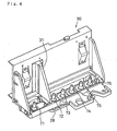
- a color ink cartridge 70a and a black ink cartridge 70b are attachable to the substantially L-shaped carriage 30 shown in Fig. 4.
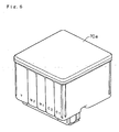
- Detailed structure of the color ink cartridge 70a is shown in Fig. 6.
- a partition wall 31 separates the black ink cartridge 70b from the color ink cartridge 70a.
- six color heads 61 through 66 for respectively discharging color inks are formed in the print head 28 that is disposed on the lower portion of the carriage 30.
- Ink supply pipes 71 through 76 for leading inks from ink tanks to the respective color heads 61 through 66 are formed upright on the bottom of the carriage 30 as shown in Fig. 4.
- the ink supply pipes 71 through 76 are inserted into connection holes formed in the respective cartridges 70a and 70b.
- inks in the ink cartridge 70 are sucked out by capillarity through the ink supply pipes 71 through 76 and are led to the color heads 61 through 66 formed in the print head 28 arranged on the lower portion of the carriage 30 as shown in Fig. 7.
- a row of nozzles 'n' are formed in each of the color heads 61 through 66 as shown in Figs. 5 and 7. In this embodiment, the number of nozzles for each color head is 32.
- a piezoelectric element PE is arranged for each row of nozzles 'n'.
- the piezoelectric element PE has a crystal structure which undergoes mechanical stress on the application of a voltage and thereby carries out extremely high-speed conversion of electrical energy to mechanical energy.
- Figs. 8A and 8B illustrate a configuration of the piezoelectric element PE and the nozzles 'n'.
- the piezoelectric element PE is disposed at a position that comes into contact with an ink conduit 68 for leading ink to the nozzles 'n'.
- application of a voltage between electrodes on either ends of the piezoelectric element PE for a predetermined time period causes the piezoelectric element PE to abruptly extend and deform one side wall of the ink conduit 68 as shown in Fig. 8B.
- the volume of the ink conduit 68 is reduced with an extension of the piezoelectric element PE, and a certain amount of ink corresponding to the volume reduction is discharged as ink particles Ip from the ends of the nozzles 'n' with a high speed.
- the ink particles Ip soak into the sheet of paper P set on the platen 26, so as to print images.
- the six color heads 61 through 66 are divided into three pairs on the print head 28 as shown in Fig. 5.
- the first pair includes the black ink head 61 that is arranged at one end close to the black ink cartridge 70b and the cyan ink head 62 that is disposed next to the black ink head 61.
- the second pair includes the head 63 for lower-density cyan ink compared with the standard cyan ink supplied to the cyan ink head 62 (hereinafter referred to as light cyan ink) and the magenta ink head 64.
- the third pair includes the head 65 for lower-density magenta ink compared with the standard magenta ink supplied to the magenta ink head 64 (hereinafter referred to as light magenta ink) and the yellow ink head 66.
- the compositions and densities of the respective inks will be discussed later.
- the printer 20 In the printer 20 of the embodiment having the hardware structure discussed above, while the sheet feed motor 22 rotates the platen 26 and the other rollers to feed the sheet of paper P, the carriage 30 is driven and reciprocated by the carriage motor 24 and the piezoelectric elements PE on the respective color heads 61 through 66 of the print head 28 are driven simultaneously.
- the printer 20 accordingly discharges the respective color inks and transfers multi-color images onto the sheet of paper P.
- the printer 20 prints multi-color images based on signals output from an image production apparatus, such as the computer 90, via the connector 56.
- an applications program 95 working in the computer 90 processes images and displays the processed images on a CRT display 93 via a video driver 91.
- a printer driver 96 in the computer 90 receives image information from the applications program 95 and the printer 20 converts the image information to printable signals.
- the printer driver 96 includes a rasterizer 97 for converting the image information processed by the applications program 95 to dot-based color information, a color correction module 98 for making the image information that has been converted to the dot-based color information (tone data) undergo color correction according to the colorimetric characteristics of an image output apparatus, such as the printer 20, and a halftone module 99 for generating halftone image information, which expresses densities in a specified area by the existence or non-existence of ink in each dot unit, from the color-corrected image information. Operations of these modules are known to the skilled in the art and are thus not specifically described here in principle. The contents of the halftone module 99 may, however, be described according to the requirements.
- the printer 20 of the embodiment has the additional heads 63 and 65 for light cyan ink and light magenta ink other than the four heads 61, 62, 64, and 66 for the standard four color inks BK, C, M, and Y in the print head 28.
- light cyan ink and light magenta ink have lower dye densities than those of standard cyan ink and magenta ink.
- Cyan ink of standard density (defined as C1 in Fig. 10) includes 3.6% by weight of Direct blue 199 as a dye, 30% by weight of diethylene glycol, 1% by weight of Surfinol 465, and 65.4% by weight of water.
- Light cyan ink (defined as C2 in Fig.
- Magenta ink of standard density (defined as M1 in Fig. 10) includes 2.8% by weight of Acid red 289 as a dye, 20% by weight of diethylene glycol, 1% by weight of Surfinol 465, and 76.2% by weight of water.
- Light magenta ink (defined as M2 in Fig. 10), on the other hand, includes only 0.7% by weight of Acid red 289, that is, one quarter the dye density of the magenta ink M1, and 25% by weight of diethylene glycol and 73.3% by weight of water for adjustment of the viscosity.
- Yellow ink Y includes 1.8% by weight of Direct Yellow 86 as a dye
- black ink BK includes 4.8% by weight of Food black 2 as a dye. All these inks are adjusted to have the viscosity of approximately 3 [mPa ⁇ s]. Adjustment of the viscosity to the substantially identical level enables identical control of the piezoelectric elements PE for the respective color heads 61 through 66.
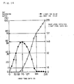
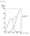
- Fig. 11 is a graph showing the lightness of these color inks.
- the abscissa of Fig. 11 denotes the recording ratio to the recording resolution of the printer, that is, the proportion of printing dots formed by the ink particles Ip discharged from the nozzles 'n' to the white sheet of paper P.
- the recording ratio 100 represents the state in which the whole surface of the sheet of paper P is covered with the ink particles Ip.
- the light cyan ink C2 has approximately one quarter the dye density (percent by weight) of the cyan ink C1.
- the lightness of the light cyan ink C2 at the recording ratio of 100% is equal to the lightness of the cyan ink C1 at the recording ratio of approximately 35%.
- the proportion of recording ratios of different-density inks giving the identical lightness is defined by the beauty of color mixture in case that the two different-density inks are mixed in print. In practice, it is desirable to adjust the proportion in the range of 20% to 50%.
- This relationship is substantially equivalent to the adjustment of the dye density (percent by weight) of the lower-density ink (light cyan ink C2 or the light magenta ink M2) to almost one fifth to one third the dye density (percent by weight) of the higher-density ink (cyan ink C1 or the magenta ink M1).
- the printer 20 of the embodiment carries out the processing in the halftone module 99 of the printer driver 96 and thereby prints images with high-density ink and low-density ink.
- Fig. 12 is a flowchart showing a halftone process routine carried out in the halftone module 99.
- the halftone module 99 receives color-corrected tone data DS (8 bits respectively for C, M, Y, and BK) of one pixel in the order along the scanning direction of the carriage 30 from the color correction module 98 at step S100.
- step S120 determines the on/off state of deep dots, based on the input tone data DS.
- the process of determining the on/off state of deep dots follows a routine of determining the formation of deep dots shown in the flowchart of Fig. 13.
- deep level data Dth is read from a table shown in Fig. 14, based on the input tone data DS at step S122.
- Fig. 14 is a table showing the recording ratios of light ink and deep ink plotted against the tone data of the original image.
- the tone data DS take the values of 0 to 255 for each color (8 bit-data for each color), and the magnitude of the tone data is accordingly expressed as 16/256 in the following description.
- deep level data Dth (right ordinate in Fig. 14) corresponding to a predetermined recording ratio of deep ink is read from the table of Fig. 14, based on the input tone data DS.
- the recording ratio of the deep cyan ink C1 is equal to 0%, so that the value of deep level data Dth is equal to zero.
- the recording ratio of the deep cyan ink C1 is equal to 7%, so that the value of deep level data Dth is equal to 18.
- the recording ratio of the deep cyan ink C1 is equal to 75%, so that the value of deep level data Dth is equal to 191.
- the corresponding recording ratios of the light cyan ink C2 are 36%, 58%, and 0%, respectively, and light level data Dtn are 92/255, 148/255, and 0/255.
- the relationship between the recording ratio of the light cyan ink C2 and the recording ratio of the cyan ink C1 shown in the table of Fig. 14 has the following characteristics:
- the procedure of this embodiment obtains the deep level data Dth according to the relationship shown in the table of Fig. 14 and carries out the following process to determine the on/off state of a deep ink dot.
- the deep level data Dth thus obtained is compared with a threshold value Dref1 at step S124.
- the threshold value Dref1 is a reference value for determining whether or not dots of deep ink should be formed in a target pixel.
- a systematic dither method using a threshold matrix of discrete dither is applied to set the threshold value.
- the threshold matrix of discrete dither used here is, for example, a wide-range matrix of 64 x 64 in size (blue noise matrix).
- Fig. 15 shows the principle of the systematic dither method. Although the matrix shown in Fig. 15 has the size of 4 x 4 as a matter of convenience of illustration, the matrix actually used has the size of 64 x 64. Threshold values (0 to 255) are specified to have no bias in appearance of threshold values in any areas included in the 64 x 64 matrix. The wide-range matrix effectively prevents occurrence of pseudo-contours.
- the discrete dither ensures high spatial frequencies of dots determined by the threshold matrix and makes dots sufficiently scattered in the specified area.
- a concrete example of the discrete dither is a Beyer's threshold matrix.
- the discrete dither causes deep dots to be sufficiently scattered and realizes a non-biased distribution of deep dots and light dots, thereby improving the picture quality.
- Another technique for example, a density pattern method or pixel distribution method, may be applied to determine the on/off state of deep dots.
- the program determines the on state of deep dots in the pixel and calculates a resulting value RV at step S126.
- the resulting value RV corresponds to the density of the pixel (deep dot evaluation value).
- the value corresponding to the density of the pixel for example, the value 255 is set as the resulting value RV.
- the resulting value RV may be a fixed value or set as a function of deep level data Dth.
- the program determines the off state of deep dots, that is, no formation of dots by high-density ink in the pixel, and sets the value '0' to the resulting value RV at step S128. Since the white background of the sheet of paper P remains in the place where no dots of high-density ink are formed, the resulting value RV is set equal to zero.
- step S130 calculate light dot data Dx used for determining the on/off state of light dots.
- corrected data DC is obtained by adding a diffusion error ⁇ Du from the processed pixel to the light dot data Dx.
- ZZ represents an evaluation value in the case of the formation of deep dots and is equal to 255 as mentioned above.
- Dx Dth + Dtn ⁇ z / 255 wherein z denotes an evaluation value in the case of the formation of light dots.
- the evaluation value in the case of the formation of light dots is smaller than the same in the case of the formation of deep dots and is set equal to 160 in this embodiment.
- the corrected data DC is obtained by adding the diffusion error ⁇ Du to the light dot data Dx, because error diffusion is carried out for light dots.
- a density error occurring for a processed pixel is distributed in advance to peripheral pixels around the processed pixel with predetermined weights.
- the processing of step S135 accordingly reads the corresponding error and causes the error to affect the target pixel to be printed next.
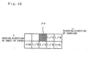
- Fig. 16 illustrates a process of distributing the error occurring for a processed pixel PP, in which the on/off state of light dots has been determined, into peripheral pixels with specified weights.
- the density error is distributed to several pixels after the processed pixel PP with the determined on/off state in the scanning direction of the carriage and in the feeding direction of the sheet of paper P with predetermined weights (1/4, 1/8, 1/16).
- step S138 it is determined whether or not the pixel is in the on state of deep dots (that is, dots of the cyan ink C1 are formed in the pixel) at step S138.
- the program proceeds to step S140 to determine the on/off state of low-density dots, that is, dots by the light cyan ink C2 (hereinafter referred to as light dots).
- the process of determining the on/off state of light dots follows a routine for determining the formation of light dots shown in the flowchart of Fig. 17.
- the error diffusion method is applied to determine the on/off state of light dots (dots by the light cyan ink C2) in this embodiment.
- the corrected tone data DC according to the principle of error diffusion is compared with a threshold value Dref2 for light dots at step S144.
- the threshold value Dref2 is a reference value for determining whether or not dots of light ink should be formed in a target pixel and is fixed to the value 127 in this embodiment.
- the threshold value Dref2 may be a variable varying with the corrected data DC.
- the threshold value Dref2 may be set as a function of corrected data DC, which has a minimum value and a maximum value in the vicinity of the minimum value and the maximum value of the corrected data DC, respectively. This effectively prevents delay of dot formation in the vicinity of the lower limit or upper limit of the tone or turbulence of dot formation (leaving a trail) observed in a certain range in the scanning direction in case of an abrupt change in tone in a specified area.
- the program determines the on state of light dots and calculates a resulting value RV (light dot evaluation value) at step S146.
- the resulting value RV here has a reference value 122 and is corrected by the corrected data DC, although it may be a fixed value.
- the program determines the off state of light dots and sets the value '0' to the resulting value RV at step S148.
- step S150 calculates an error ERR.
- the error ERR is obtained by subtracting the resulting value RV from the corrected data DC.
- the resulting value RV is equal to zero and the corrected data DC is set to the error ERR.
- the resulting value RV has a value corresponding to the dots, so that the difference between the corrected data DC and the resulting value RV is specified as the error ERR.
- the program carries out an error diffusion process.
- the error ERR obtained at step S150 is distributed into peripheral pixels around the processed pixel with predetermined weights (see Fig. 16).
- the program moves to a next pixel and repeats the processing of steps S100 through S160 for the next pixel.
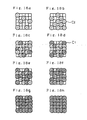
- Figs. 18a through 18h show examples of printing states of light dots and deep dots, with respect to the cyan ink C1 and the light cyan ink C2.
- dots of only the light cyan ink C2 are formed as shown in Figs. 18a and 18b.
- the proportion of light dots existing in a predetermined area increases with an increase in tone data.
- the formation of deep dots starts and gradually increases while the proportion of light dots still increases as shown in Fig. 18c.
- the proportion of deep dots increases while the proportion of light dots decreases as shown in Figs. 18d and 18e.
- the printer 20 of this embodiment prints images with two different inks having approximately four-fold difference in dye density.
- This structure lowers the degree of granularity especially in a low tone area and improves the printing quality.
- the formation of deep dots by high-density ink starts in the range of tone data smaller than the specific value of tone data that gives the maximum recording ratio of light dots by low-density ink (the light cyan ink C2 in the example of Fig. 14). This results in smooth color mixture at a joint between the record with light dots and the record with deep dots, thereby ensuring extremely high printing quality.
- the maximum recording ratio of dots by light ink can be reduced to approximately 60%. This does not cause a solid state of light ink in a low tone area, thereby preventing a pseudo-contour from being observed in the low tone area.
- This structure also ensures a high degree of freedom in distribution of dots by deep ink and accordingly gives a smooth distribution without any incompatibility.
- the resulting expression in the tone area where dots of high-density ink and dots of low-density ink start mixing is favorably natural.
- the recording ratio of dots by light ink abruptly decreases. Dots of light ink are replaced by dots of deep ink with an increase in tone data. The replacement decreases the number of ink dots required for expressing a certain tone. This saves the amount of ink discharged and thereby the total amount of ink used.
- the relationship between the magnitude of tone data and the recording ratios of dots by light ink and deep ink is not limited to the table of Fig. 14.
- the value of tone data at which the formation of dots by deep ink starts may be set to be significantly lower than the value of the embodiment as shown by curves of solid line Jcl and Jc2 in the table of Fig. 19.
- the value of tone data at which the recording ratio of dots by light ink reaches substantially zero may be set to be significantly larger than the value of the embodiment as shown by curves of broken line Bcl and Bc2 in the table of Fig. 19.
- the recording ratio of dots by light ink may decrease by an extremely large rate in the range of tone data larger than the specific value of tone data that gives the maximum recording ratio of dots by light ink as shown in Fig. 20.
- the color ink cartridge 70a is separate from the black ink cartridge 70b. This allows the black ink cartridge 70b that is more frequently used for printing characters and the color ink cartridge 70a to be replaced at arbitrary timings.
- inks of the same color (cyan or magenta) but different densities are arranged adjacent to each other. Namely the physical distance between the higher-density ink and the lower-density ink is fixed for each color. This enables the position of dots by deep ink and light ink to be adjusted accurately.
- a number of nozzles are formed in the feeding direction of the sheet of paper P in the structure of the embodiment. This structure enables high-speed printing.
- inks of different densities are used only for cyan and magenta in the embodiment, inks of different densities may also be used for yellow and black. Inks of different densities are not restricted to the combination of C, M, Y, and BK but may be applied to other combinations. Inks of different densities may be used for special colors, such as gold and silver.
- the program for regulating deep dots and light dots is set in the printer driver 96 of the computer 90.
- the program may, however, be set in the printer 20.
- the computer 90 sends image information written in a language, such as PostScript, and the printer 20 has the halftone module 99 and the other required elements.
- the software realizing these functions is stored in the hard disk 16 of the computer 90 and incorporated into the operating system in the form of the printer driver at the time of activation of the computer 90.
- the software may be stored in a portable storage medium (carriable storage medium), such as floppy disks and CD-ROMs, and transferred from the storage medium to the main memory of the computer system or an external storage device.
- the software may be transferred from the computer 90 to the printer 20.
- the printing system 10 includes an apparatus for supplying the software via a communication line
- the contents of the halftone module may be transferred to either the computer 90 or the printer 20 via the communication line.
- the decrease may be based on a characteristic that decreases the recording ratio of light dots at a greater rate than a rate of a characteristic that allows the determination of a recording ratio of dark dots and the recording ratio of light dots in proportion to the magnitude of the tone signal.
- the abrupt decrease may be such that the recording ratio of the light ink decreases substantially to zero before the recording ratio of the deeper ink reaches a recording ratio of 100%.
- the abrupt decrease may be such that the recording ratio decreases at a high rate and then at a lower rate, the recording ratio dropping by a larger amount over the higher rate period than over the lower rate period.
- a printer 200 of the second embodiment has the same hardware structure as that of the printer 20 of the first embodiment.
- the only difference from the first embodiment is the processing carried out in the halftone module 99 of the computer 90.
- the processing in the halftone module 99 refers to the relationship shown in the table of Fig. 14, in order to determine the recording ratios of dots by deep ink and light ink based on the tone data of pixels in an original image.
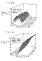
- the processing in the halftone module 99 refers to the graphs of Figs. 21A and 21B. As shown in Figs.
- the recording ratios of dots by light ink and deep ink are varied not only with the tone data of a target color ink to be currently processed by the halftone module 99, for example, the tone data of cyan ink, but also with the tone data of another color ink included in a target pixel, for example, the tone data of magenta ink.
- the processing in the halftone module 99 decreases the recording ratio of dots by the light cyan ink C2 while increasing the recording ratio of dots by the cyan ink C1 as shown in Figs. 21A and 21B.
- the processing in the halftone module 99 decreases the recording ratio of dots by the light magenta ink M2 while increasing the recording ratio of dots by the magenta ink M1 as shown in Figs. 22A and 22B.
- the structure of the second embodiment prints images with two inks of different dye densities and starts the formation of deep dots by high-density ink (the cyan ink C1 in the example of Fig. 14) in the range of tone data smaller than the specific value of tone data that gives the maximum recording ratio of light dots by low-density ink (the light cyan ink C2 in the example of Fig. 14).
- the structure of the second embodiment decreases the recording ratio of dots by low-density ink (C2 or M2) while increasing the recording ratio of dots by high-density ink (C1 or M1), with an increase in density of another color ink required for a target pixel. Because of the stain of another color ink, this method keeps the degree of granularity substantially equal to the level in the monochromatic case.
- the structure of the second embodiment starts the formation of dots by deep ink in the range of tone data smaller than the specific value of tone data that gives the maximum recording ratio of dots by light ink.
- the second embodiment lowers the limit of the formation of dots by light ink and advances the formation of dots by deep ink.
- This structure also ensures natural expression in the tone range where dots of high-density ink and dots of low density ink start mixing.
- the structure of the second embodiment replaces dots of low-density ink (light cyan ink C2 or light magenta ink M2) with dots of high-density ink (cyan ink C1 or magenta ink M1) to be recorded at the position corresponding to the target pixel.
- This structure reduces the total amount of ink discharged per unit area in the sheet of paper, without deteriorating the picture quality. This enables discharge of each color ink with a sufficient margin to the ink duty set for each paper, that is, restriction of the amount of ink dischargeable per unit area.
- the structure of the second embodiment thus effectively prevents the sheet of paper from being swollen with ink or unnatural color expression due to the restriction of ink duty.
- the structure of the second embodiment first specifies the densities (tone data) of cyan, magenta, and yellow required for realizing the hue of a target pixel, and then determines the recording ratios of dots by deep ink and light ink of each color, based on the correlation of tone data.
- the recording ratios of dots by deep ink and light ink of each color may be determined directly from RGB data of a target pixel in a printer driver.
- a rasterizer 297, a color correction/halftone module 299, and a look-up table 300 are arranged inside a printer driver 296.
- the procedure of the modified example refers to the look-up table 300 and determines the recording ratios of light ink and deep ink for cyan and magenta and the recording ratio of yellow ink, directly based on the RGB data.
- Figs. 24A and 24B show examples of the look-up table used for determining the recording ratios of dots by the light cyan ink C2 and the cyan ink C1 directly from the RGB data of a target pixel.
- the procedure of the modified application determines the recording ratios of the respective color inks directly from the RGB data and thereby simplifies the structure.
- Both the second embodiment and its modified example decrease the recording ratio of dots by light ink for cyan (or magenta) while increasing the recording ratio of dots by deep ink with an increase in density of magenta (or cyan) required for the target pixel.
- the recording ratios of dots by deep ink and light ink may also be varied by the density of yellow.
- an applicable procedure replaces the three color inks by black ink.
- the procedure decreases the recording ratio of dots by the light cyan ink C2 or the light magenta ink M2 and increases the recording ratio of dots by the cyan ink C1 or the magenta ink M1 according to the density of black ink.
- the recording ratio of dots by the light cyan ink C2 or the light magenta ink M2 is decreased according to the density of magenta ink or the density of cyan ink at the position corresponding to the target pixel.
- the principle of the present invention is, however, not restricted to this relationship.
- the recording ratio of dots by light ink and the recording ratio of dots by deep ink can be arbitrarily determined according to the density of another ink at the position corresponding to the target pixel.
- a possible procedure temporarily decreases the amount of deep ink and increases the amount of light ink, in the process of lowering the recording ratio of dots by light ink or replacing three colors by black in a pixel where all the three colors, that is, cyan, magenta, and yellow, exist. This procedure lowers the degree of granularity at the joint.
- a predetermined voltage is applied to the piezoelectric elements PE for a predetermined time period, in order to discharge both light ink and deep ink.
- Another method is, however, applicable to discharge inks.
- the available ink-discharge techniques can be classified into two types; that is, the method of separating ink particles from a continuous jet stream of ink and the on-demand method applied in the above embodiments.
- the former type includes a charge modulation method that separates droplets of ink from a jet stream of ink by means of charge modulation and a micro-dot method that utilizes fine satellite particles produced in the process of separating large-diametral particles from a jet stream of ink.
- the on-demand type produces ink particles for the respective dot units according to the requirements.
- a method included in the on-demand type other than the method utilizing the piezoelectric elements applied in the above embodiments, arranges a heating body HT in the vicinity of nozzles NZ of ink, produces bubbles BU by heating ink, and makes ink particles IQ discharged by the pressure of the bubbles BU as shown in Figs. 25A through 25E.
- Such on-demand type methods are also applicable to the printing system of the present invention that uses inks of different densities.
Claims (18)
- Système d'impression ayant une tête (28), depuis laquelle au moins deux encres de densité différente peuvent être déchargées pour une certaine couleur, et enregistrant une image composée de plusieurs tons par une répartition de points par lesdites au moins deux encres de densité différente, ledit système d'impression comprenant :des moyens d'entrée (50) destinés à recevoir des signaux de tons d'une image originale à imprimer ;des moyens de définition (99) destinés à définir une caractéristique d'enregistrement qui commence la formation de points par une encre de densité supérieure dans une plage desdits signaux de tons inférieure à un signal de ton spécifique qui donne une densité d'enregistrement maximum de points par une encre de densité inférieure ;des moyens de spécification (99) destinés à spécifier l'existence et la non-existence de points par lesdites au moins deux encres de densité différente selon lesdits signaux de tons, sur la base de ladite caractéristique d'enregistrement ; etdes moyens de régulation (99) destinés à la décharge de chaque encre depuis ladite tête, de manière à réaliser une expression de ton selon ladite existence et non-existence de points par lesdites au moins deux encres de densité différente.
- Système d'impression selon la revendication 1, dans lequel lesdits moyens de définition (99) définissent en outre ladite caractéristique d'enregistrement de telle manière qu'une densité d'enregistrement de points par une encre de densité inférieure dans une plage desdits signaux de tons supérieure à un signal de ton spécifique qui donne une densité d'enregistrement maximum de points par ladite encre de densité inférieure, diminue brusquement.
- Système d'impression selon la revendication 1 ou 2, dans lequel lesdits moyens de définition (99) ont une table permettant de spécifier les densités d'enregistrement de points par lesdites au moins deux encres de densité différente correspondant auxdits signaux de tons.
- Système d'impression selon la revendication 1, 2 ou 3, dans lequel lesdites au moins deux encres de densité différente comprennent une encre de haute densité et une encre de faible densité et une densité de coloration de ladite encre de faible densité représente approximativement un quart d'une densité de coloration de ladite encre de haute densité.
- Système d'impression selon l'une quelconque des revendications précédentes, dans lequel ladite tête (28) comprend une pluralité de têtes pour décharger lesdites au moins deux encres de densité différente par rapport à une pluralité d'encres de couleur ayant des nuances différentes,
ledit système d'impression comprenant en outre un ensemble desdits moyens de définition, desdits moyens de spécification, et desdits moyens de régulation correspondant à ladite pluralité d'encres de couleur ayant des nuances différentes. - Système d'impression selon la revendication 5, dans lequel ladite pluralité d'encres de couleur ayant différentes nuances comprend la nuance d'encre cyan et la nuance d'encre magenta.
- Système d'impression selon la revendication 5 ou 6, dans lequel chacun desdits moyens de spécification (99) spécifie des densités d'enregistrement par rapport à une encre de couleur, en liaison avec lesdits signaux de tons d'une autre encre de couleur.
- Système d'impression selon la revendication 5, 6 ou 7, dans lequel chacun desdits moyens de spécification (99) comprend des moyens de correction destinés à diminuer la densité d'enregistrement de points par ladite encre de densité inférieure dans un pixel cible avec une augmentation de densité d'une autre encre de couleur déchargée vers ledit pixel cible.
- Système d'impression selon l'une quelconque des revendications 5 à 8, dans lequel chacun desdits moyens de définition a une table de consultation permettant de spécifier directement les densités d'enregistrement de points profonds et de points légers par rapport à ladite pluralité d'encres de couleur ayant des nuances différentes, à partir desdits signaux de tons.
- Système d'impression selon l'une quelconque des revendications précédentes, comprenant :une tête (28) destinée à décharger une pluralité d'encres de couleur ayant des nuances différentes ainsi qu'au moins deux encres de densité différente par rapport à l'une de ladite pluralité d'encres de couleur ayant des nuances différentes ;des moyens de détermination de fréquence de points (99) destinés à spécifier les densités d'enregistrement de points par ladite pluralité d'encres de couleur ayant des nuances différentes sur la base desdits signaux de tons, et à déterminer une densité d'enregistrement de points formés dans un pixel cible par une encre de faible densité parmi lesdites au moins deux encres de densité différente, en liaison avec une densité d'une autre encre de couleur déchargée vers ledit pixel cible ; etdes moyens d'enregistrement (99) destinés à réguler la décharge de chaque encre depuis ladite tête, de manière à enregistrer lesdits points par ladite pluralité d'encres de couleur ayant des nuances différentes ainsi que des points profonds et des points légers par lesdites au moins deux encres de densité différente sur un support d'enregistrement.
- Système d'impression selon la revendication 10, dans lequel lesdits moyens de détermination de fréquence de points (99) comprennent des moyens de correction destinés à corriger ladite densité d'enregistrement de points formés dans ledit pixel cible par ladite encre de faible densité, sur la base d'un rapport qui réduit la densité d'enregistrement de points par ladite encre de faible densité avec une augmentation de densité d'une autre encre de couleur déchargée vers ledit pixel cible.
- Système d'impression selon la revendication 11, dans lequel lesdits moyens de détermination de fréquence de points (99) comprennent une table de consultation permettant de spécifier directement les densités d'enregistrement desdits points profonds et desdits points légers par rapport à ladite pluralité d'encres de couleur ayant des nuances différentes, à partir desdits signaux de tons.
- Système d'impression selon l'une quelconque des revendications précédentes, dans lequel (28) ladite tête comprend un mécanisme destiné à décharger des particules d'encre sous une pression exercée sur chaque encre s'écoulant par un conduit d'encre par application d'une tension à un élément piézoélectrique disposé dans ledit conduit d'encre.
- Système d'impression selon l'une quelconque des revendications 1 à 12, dans lequel (28) ladite tête comprend un mécanisme destiné à décharger des particules d'encre sous une pression exercée sur chaque encre s'écoulant à travers un conduit d'encre par des bulles d'air produites par une alimentation en électricité d'un corps chauffant disposé dans ledit conduit d'encre.
- Système d'impression selon la revendication 13 ou 14, dans lequel ladite tête (28) a une pluralité de buses destinées à pulvériser lesdites particules d'encre par rapport à chaque encre de couleur de chaque densité, ladite pluralité de buses étant agencée dans un sens d'alimentation d'une feuille de papier, sur laquelle l'image est créée.
- Procédé de contrôle d'une tête (28), depuis laquelle au moins deux encres de densité différente peuvent être déchargées pour une certaine couleur, et de régulation d'une répartition de points par lesdites au moins deux encres de densité différente sur la base de signaux de tons d'une image originale à imprimer, de manière à enregistrer une image composée de plusieurs tons, ledit procédé comprenant les étapes consistant à :mémoriser une caractéristique d'enregistrement qui commence la formation de points par une encre de densité supérieure dans une plage de signaux de tons inférieure à un signal spécifique qui donne une densité d'enregistrement maximum de points par une encre de densité inférieure ;entrer les signaux de tons de ladite image originale à imprimer ;spécifier l'existence et la non-existence de points par lesdites au moins deux encres de densité différente selon les signaux de tons entrés, sur la base de ladite caractéristique d'enregistrement ; etréguler la décharge de chaque encre depuis ladite tête, de manière à réaliser une expression de ton selon l'existence et la non-existence de points par lesdites au moins deux encres de densité différente.
- Procédé de contrôle d'une tête (28) selon la revendication 16, dans lequel ladite étape de mémorisation d'une caractéristique d'enregistrement comprend en outre :la mémorisation d'une caractéristique d'enregistrement qui diminue de façon abrupte une densité d'enregistrement de points par une encre de densité inférieure dans une plage de signaux de tons supérieure à un signal de ton spécifique qui donne une densité d'enregistrement maximum de points par ladite encre de densité inférieure.
- Procédé de contrôle d'une tête (28) selon la revendication 16 ou 17, comprenant en outre les étapes consistant à :fournir une tête destinée à décharger une pluralité d'encres de couleur ayant des nuances différentes ainsi qu'au moins deux encres de densité différente par rapport à l'une de ladite pluralité d'encres de couleur ayant des nuances différentes ;spécifier les densités d'enregistrement de points par ladite pluralité d'encres de couleur ayant des nuances différentes sur la base desdits signaux de tons entrés, et déterminer une densité d'enregistrement de points formés dans un pixel cible par une encre de basse densité parmi lesdites au moins deux encres de densité différente, en liaison avec une densité d'une autre encre de couleur déchargée vers ledit pixel cible ; etréguler la décharge de chaque encre depuis ladite tête, de manière à enregistrer les points par ladite pluralité d'encres de couleur ayant des nuances différentes ainsi que des points profonds et des points légers par lesdites au moins deux encres de densité différente sur un support d'enregistrement.
Priority Applications (1)
| Application Number | Priority Date | Filing Date | Title |
|---|---|---|---|
| EP04028216A EP1515538B1 (fr) | 1996-06-27 | 1997-06-27 | Système d'impression utilisant des encres à densité différente et procédé d'enregistrement d'images |
Applications Claiming Priority (6)
| Application Number | Priority Date | Filing Date | Title |
|---|---|---|---|
| JP18823396 | 1996-06-27 | ||
| JP18823396 | 1996-06-27 | ||
| JP188233/96 | 1996-06-27 | ||
| JP297608/96 | 1996-10-18 | ||
| JP29760896 | 1996-10-18 | ||
| JP29760896 | 1996-10-18 |
Related Child Applications (1)
| Application Number | Title | Priority Date | Filing Date |
|---|---|---|---|
| EP04028216A Division EP1515538B1 (fr) | 1996-06-27 | 1997-06-27 | Système d'impression utilisant des encres à densité différente et procédé d'enregistrement d'images |
Publications (3)
| Publication Number | Publication Date |
|---|---|
| EP0817464A2 EP0817464A2 (fr) | 1998-01-07 |
| EP0817464A3 EP0817464A3 (fr) | 2000-03-08 |
| EP0817464B1 true EP0817464B1 (fr) | 2006-08-09 |
Family
ID=26504795
Family Applications (2)
| Application Number | Title | Priority Date | Filing Date |
|---|---|---|---|
| EP04028216A Expired - Lifetime EP1515538B1 (fr) | 1996-06-27 | 1997-06-27 | Système d'impression utilisant des encres à densité différente et procédé d'enregistrement d'images |
| EP97304670A Expired - Lifetime EP0817464B1 (fr) | 1996-06-27 | 1997-06-27 | Système d'impression utilisant des encres à densité différente et procédé correspondant |
Family Applications Before (1)
| Application Number | Title | Priority Date | Filing Date |
|---|---|---|---|
| EP04028216A Expired - Lifetime EP1515538B1 (fr) | 1996-06-27 | 1997-06-27 | Système d'impression utilisant des encres à densité différente et procédé d'enregistrement d'images |
Country Status (4)
| Country | Link |
|---|---|
| US (1) | US5795082A (fr) |
| EP (2) | EP1515538B1 (fr) |
| JP (8) | JP4434304B2 (fr) |
| DE (1) | DE69736453T2 (fr) |
Families Citing this family (32)
| Publication number | Priority date | Publication date | Assignee | Title |
|---|---|---|---|---|
| JP3208777B2 (ja) | 1996-07-18 | 2001-09-17 | セイコーエプソン株式会社 | 印刷装置および画像記録方法 |
| US6215561B1 (en) * | 1997-02-28 | 2001-04-10 | Seiko Epson Corporation | Image processing apparatus and image processing method |
| US6256110B1 (en) * | 1997-06-11 | 2001-07-03 | Canon Kabushiki Kaisha | Image processing apparatus and method and storage medium |
| JP3683387B2 (ja) * | 1997-08-01 | 2005-08-17 | シャープ株式会社 | ネットワークコンピュータ内蔵プリンタおよびこれを備えたコンピュータネットワークシステム |
| US6178008B1 (en) * | 1997-10-30 | 2001-01-23 | Hewlett-Packard Company | Constructing device-state tables for inkjet printing |
| JP3819573B2 (ja) * | 1997-11-19 | 2006-09-13 | セイコーエプソン株式会社 | 印刷装置および印刷方法並びに記録媒体 |
| US6439682B1 (en) * | 1998-03-05 | 2002-08-27 | Seiko Epson Corporation | Printing method, printing apparatus, and recording medium |
| JP2000006445A (ja) * | 1998-06-26 | 2000-01-11 | Seiko Epson Corp | 印刷装置および印刷方法並びに記録媒体 |
| JP2000103045A (ja) * | 1998-09-30 | 2000-04-11 | Nec Corp | インクジェット式プリンタ及び印刷方法 |
| EP1370068A1 (fr) * | 1999-03-31 | 2003-12-10 | Agfa-Gevaert | Amélioration de la qualité d'impression en couleur en utilisant des particules de marques avec un angle de phase spécifique |
| TW522099B (en) * | 1999-03-31 | 2003-03-01 | Seiko Epson Corp | Printing system, printing controller, printer, method for controlling printing operations, printing method, ink box, ink provider, and recording medium |
| EP1043883B1 (fr) * | 1999-04-06 | 2011-07-27 | Canon Kabushiki Kaisha | Scanner, imprimante, support d'enregistrement et proc?d? de traitement d'images |
| US6312101B1 (en) * | 1999-12-06 | 2001-11-06 | Eastman Kodak Company | Method of printing digital images using multiple colorants having substantially the same color |
| US6765693B1 (en) | 2000-03-20 | 2004-07-20 | Sharp Laboratories Of America, Inc. | Photo quality color printing by using light black ink |
| JP3870046B2 (ja) * | 2000-08-31 | 2007-01-17 | キヤノン株式会社 | 記録装置及び記録方法 |
| US6798538B1 (en) | 2000-09-08 | 2004-09-28 | Canon Kabushiki Kaisha | Halftoning at multiple different resolutions |
| JP4386233B2 (ja) | 2001-08-01 | 2009-12-16 | キヤノン株式会社 | 画像処理方法 |
| US6435657B1 (en) * | 2001-08-20 | 2002-08-20 | Eastman Kodak Company | Method for multicolorant printing of digital images using reduced colorant amounts |
| US7229146B2 (en) * | 2002-04-08 | 2007-06-12 | Agfa Graphics Nv | System and method for characterizing a printing device |
| JP4371640B2 (ja) * | 2002-09-09 | 2009-11-25 | キヤノン株式会社 | カラー出力方法及び出力装置 |
| JP4432380B2 (ja) * | 2003-07-08 | 2010-03-17 | セイコーエプソン株式会社 | 印刷領域に応じてドットの記録率を変える印刷 |
| JP4189674B2 (ja) * | 2004-01-15 | 2008-12-03 | セイコーエプソン株式会社 | 色修正データ作成装置、色修正データ作成方法、色修正データ作成プログラム、印刷制御装置、印刷制御方法および印刷制御プログラム |
| US7349877B2 (en) * | 2004-03-02 | 2008-03-25 | Accenture Global Services Gmbh | Total return to shareholder analytics |
| US7591889B2 (en) | 2004-10-08 | 2009-09-22 | Hewlett-Packard Development Company, L.P. | Dissimilar pigments for use in dark and light inkjet inks |
| US7533980B2 (en) * | 2005-02-15 | 2009-05-19 | Hewlett-Packard Development Company, L.P. | Ink set and media for ink-jet printing |
| US8553281B2 (en) * | 2008-12-05 | 2013-10-08 | Alpha Technologies Inc. | High density, high intensity ink formulation and method for printing high intensity colors |
| CN102378691B (zh) | 2009-03-31 | 2014-07-30 | 惠普开发有限公司 | 喷墨笔、制造喷墨笔的方法和清洗喷墨笔的方法 |
| JP6066579B2 (ja) * | 2012-04-19 | 2017-01-25 | キヤノン株式会社 | 画像処理装置及びその制御方法 |
| JP6848287B2 (ja) * | 2016-09-16 | 2021-03-24 | セイコーエプソン株式会社 | 印刷装置、印刷方法、および、コンピュータープログラム |
| JP6848288B2 (ja) * | 2016-09-16 | 2021-03-24 | セイコーエプソン株式会社 | 印刷装置、印刷方法、および、コンピュータープログラム |
| JP2019081267A (ja) * | 2017-10-30 | 2019-05-30 | セイコーエプソン株式会社 | カートリッジ |
| JP7103183B2 (ja) | 2018-11-16 | 2022-07-20 | セイコーエプソン株式会社 | 色変換プロファイル作成装置、色変換プロファイルの作成方法およびそのためのプログラム |
Family Cites Families (37)
| Publication number | Priority date | Publication date | Assignee | Title |
|---|---|---|---|---|
| JPS58219867A (ja) * | 1982-06-14 | 1983-12-21 | Canon Inc | 色再現方式 |
| US4560997A (en) * | 1982-07-07 | 1985-12-24 | Canon Kabushiki Kaisha | Method and apparatus for forming a pattern |
| DE3326330C2 (de) * | 1982-07-23 | 1994-06-09 | Canon Kk | Verfahren zur Erzeugung eines Graustufenbildes |
| GB2139450B (en) * | 1983-03-08 | 1987-12-16 | Canon Kk | Color picture forming apparatus |
| JPS59201864A (ja) * | 1983-04-28 | 1984-11-15 | Canon Inc | 画像形成方法 |
| JPS59215889A (ja) * | 1983-05-24 | 1984-12-05 | Canon Inc | インクジエツト記録方法 |
| JPS6056557A (ja) * | 1983-09-09 | 1985-04-02 | Canon Inc | インクジェット記録方法 |
| JPS60126965A (ja) * | 1983-12-13 | 1985-07-06 | Fuji Xerox Co Ltd | 画情報記録装置 |
| JPS61108254A (ja) * | 1984-10-31 | 1986-05-26 | Canon Inc | 階調記録方法 |
| JPH0691612B2 (ja) * | 1987-03-11 | 1994-11-14 | 株式会社ヤマトヤ商会 | 画像の階調変換方法 |
| US4855753A (en) | 1987-06-19 | 1989-08-08 | Canon Kabushiki Kaisha | Method of ink jet recording and ink jet recording apparatus |
| JPS6482960A (en) * | 1987-09-25 | 1989-03-28 | Canon Kk | Ink jet recorder |
| JPH0764081B2 (ja) * | 1987-06-19 | 1995-07-12 | キヤノン株式会社 | インクジェット記録方法 |
| JP2713995B2 (ja) * | 1988-06-17 | 1998-02-16 | キヤノン株式会社 | インクジエツト記録方法及びインクジエツト記録装置 |
| JPS641545A (en) * | 1987-06-25 | 1989-01-05 | Canon Inc | Gradation recording method |
| US4860026A (en) * | 1987-06-25 | 1989-08-22 | Canon Kabushiki Kaisha | Halftone image recording method using recording data having a plurality of concentrations for one color |
| JP2614620B2 (ja) * | 1987-09-07 | 1997-05-28 | キヤノン株式会社 | 色処理方法 |
| JPH0614688B2 (ja) * | 1987-12-09 | 1994-02-23 | 大日本スクリーン製造株式会社 | 色分解画像走査記録装置を使用するカラー原画の単色複製方法 |
| JP2807462B2 (ja) * | 1988-03-17 | 1998-10-08 | 株式会社リコー | 液体噴射記録方法 |
| US4959790A (en) * | 1988-06-28 | 1990-09-25 | F & S Corporation Of Columbus, Georgia | Apparatus and method for producing color corrected reproduction of colored original images |
| US5345315A (en) * | 1988-11-23 | 1994-09-06 | Imatec, Ltd. | Method and system for improved tone and color reproduction of electronic image on hard copy using a closed loop control |
| JPH02215541A (ja) | 1989-02-17 | 1990-08-28 | Canon Inc | 記録装置 |
| JP2786254B2 (ja) * | 1989-06-02 | 1998-08-13 | キヤノン株式会社 | インクジェット記録装置 |
| JPH0380767A (ja) * | 1989-08-24 | 1991-04-05 | Ricoh Co Ltd | 画像の階調記録装置 |
| US5146236A (en) * | 1989-12-14 | 1992-09-08 | Ricoh Company, Ltd. | Ink jet record apparatus |
| JP2768795B2 (ja) * | 1990-03-23 | 1998-06-25 | キヤノン株式会社 | インクジェット記録装置 |
| JP3184512B2 (ja) * | 1990-06-20 | 2001-07-09 | キャノン株式会社 | 画像処理装置、及び画像処理方法 |
| US5430469A (en) * | 1991-06-05 | 1995-07-04 | Canon Kabushiki Kaisha | Tone recording method using ink recording head |
| ATE235376T1 (de) * | 1991-07-30 | 2003-04-15 | Canon Kk | Vorrichtung und verfahren zum tintenstrahlaufzeichnen |
| JP2991572B2 (ja) * | 1991-09-11 | 1999-12-20 | キヤノン株式会社 | 画像記録装置 |
| JPH05276368A (ja) * | 1992-03-26 | 1993-10-22 | Canon Inc | カラー画像処理方法及び装置 |
| JP3159416B2 (ja) * | 1993-05-18 | 2001-04-23 | 富士写真フイルム株式会社 | 画像処理方法および装置 |
| JPH07132619A (ja) * | 1993-06-30 | 1995-05-23 | Canon Inc | カラーインクジェット記録装置 |
| DE69417315T2 (de) * | 1993-07-30 | 1999-09-23 | Canon Kk | Tintenstrahldruckgerät und Tintenstrahldruckverfahren |
| JP3103723B2 (ja) * | 1994-07-19 | 2000-10-30 | キヤノン株式会社 | 記録方法および記録装置 |
| US5572632A (en) * | 1994-10-07 | 1996-11-05 | Laser Master Corporation | Universal frame buffer for a rendering device |
| AUPN234595A0 (en) * | 1995-04-12 | 1995-05-04 | Eastman Kodak Company | Improvements in image halftoning |
-
1997
- 1997-06-25 US US08/882,289 patent/US5795082A/en not_active Expired - Lifetime
- 1997-06-27 EP EP04028216A patent/EP1515538B1/fr not_active Expired - Lifetime
- 1997-06-27 EP EP97304670A patent/EP0817464B1/fr not_active Expired - Lifetime
- 1997-06-27 DE DE69736453T patent/DE69736453T2/de not_active Expired - Lifetime
-
2009
- 2009-02-09 JP JP2009026840A patent/JP4434304B2/ja not_active Expired - Lifetime
- 2009-07-13 JP JP2009164502A patent/JP4553059B2/ja not_active Expired - Lifetime
- 2009-12-21 JP JP2009288896A patent/JP2010100063A/ja active Pending
-
2010
- 2010-05-10 JP JP2010107879A patent/JP4737339B2/ja not_active Expired - Lifetime
-
2011
- 2011-03-07 JP JP2011048891A patent/JP2011105020A/ja not_active Withdrawn
- 2011-07-19 JP JP2011158176A patent/JP2011245866A/ja not_active Withdrawn
-
2012
- 2012-01-16 JP JP2012006572A patent/JP5071596B2/ja not_active Expired - Lifetime
- 2012-01-16 JP JP2012006570A patent/JP5071595B2/ja not_active Expired - Lifetime
Also Published As
| Publication number | Publication date |
|---|---|
| JP4434304B2 (ja) | 2010-03-17 |
| JP2010188738A (ja) | 2010-09-02 |
| EP1515538A1 (fr) | 2005-03-16 |
| JP2011245866A (ja) | 2011-12-08 |
| JP2010100063A (ja) | 2010-05-06 |
| EP0817464A3 (fr) | 2000-03-08 |
| JP2011105020A (ja) | 2011-06-02 |
| DE69736453D1 (de) | 2006-09-21 |
| JP4737339B2 (ja) | 2011-07-27 |
| EP1515538B1 (fr) | 2011-08-24 |
| DE69736453T2 (de) | 2007-05-03 |
| JP5071596B2 (ja) | 2012-11-14 |
| JP4553059B2 (ja) | 2010-09-29 |
| EP0817464A2 (fr) | 1998-01-07 |
| JP2009234269A (ja) | 2009-10-15 |
| JP2012071619A (ja) | 2012-04-12 |
| US5795082A (en) | 1998-08-18 |
| JP2012071620A (ja) | 2012-04-12 |
| JP2009101703A (ja) | 2009-05-14 |
| JP5071595B2 (ja) | 2012-11-14 |
Similar Documents
| Publication | Publication Date | Title |
|---|---|---|
| EP0817464B1 (fr) | Système d'impression utilisant des encres à densité différente et procédé correspondant | |
| EP1515539B1 (fr) | Cartouche d'encre | |
| EP0820187B1 (fr) | Système d'impression et procédé d'enregistrement d'images | |
| US6031627A (en) | Printing system and image recording method | |
| US6338538B1 (en) | Printing system and method of recording images | |
| JP3785775B2 (ja) | 印刷装置,画像処理方法およびこの方法を実現するプログラムを記録した記録媒体 | |
| US6731401B1 (en) | Printing system having a plurality of storage buffers having a total capacity, corresponding to the number of pixels in only one scanning line | |
| JPH10175318A (ja) | 濃淡インクを用いた印刷装置、これに用いるカートリッジ、画像記録方法および記録媒体 | |
| JP4525818B2 (ja) | 印刷装置および画像記録方法 | |
| JP4265622B2 (ja) | 濃淡インクを用いた印刷装置、画像記録方法および記録媒体 | |
| JP2008132796A (ja) | 濃淡インクを用いた印刷装置、これに用いるカートリッジ、画像記録方法および記録媒体 | |
| JP2003266678A (ja) | 濃淡インクを用いた印刷装置、これに用いるカートリッジ、画像記録方法および記録媒体 | |
| JP2003154690A (ja) | インクカートリッジ |
Legal Events
| Date | Code | Title | Description |
|---|---|---|---|
| PUAI | Public reference made under article 153(3) epc to a published international application that has entered the european phase |
Free format text: ORIGINAL CODE: 0009012 |
|
| AK | Designated contracting states |
Kind code of ref document: A2 Designated state(s): DE FR GB |
|
| AX | Request for extension of the european patent |
Free format text: AL;LT;LV;SI |
|
| RIC1 | Information provided on ipc code assigned before grant |
Free format text: 6H 04N 1/40 A, 6H 04N 1/52 B |
|
| PUAL | Search report despatched |
Free format text: ORIGINAL CODE: 0009013 |
|
| AK | Designated contracting states |
Kind code of ref document: A3 Designated state(s): AT BE CH DE DK ES FI FR GB GR IE IT LI LU MC NL PT SE |
|
| AX | Request for extension of the european patent |
Free format text: AL;LT;LV;SI |
|
| 17P | Request for examination filed |
Effective date: 20000831 |
|
| AKX | Designation fees paid |
Free format text: DE FR GB |
|
| 17Q | First examination report despatched |
Effective date: 20040929 |
|
| RTI1 | Title (correction) |
Free format text: PRINTING SYSTEM UTILIZING INKS OF DIFFERENT DENSITIES AND METHOD THEREFOR |
|
| GRAP | Despatch of communication of intention to grant a patent |
Free format text: ORIGINAL CODE: EPIDOSNIGR1 |
|
| RIN1 | Information on inventor provided before grant (corrected) |
Inventor name: KAKUTANI, TOSHIAKI Inventor name: SHIMADA, KAZUMICHI |
|
| GRAS | Grant fee paid |
Free format text: ORIGINAL CODE: EPIDOSNIGR3 |
|
| GRAA | (expected) grant |
Free format text: ORIGINAL CODE: 0009210 |
|
| AK | Designated contracting states |
Kind code of ref document: B1 Designated state(s): DE FR GB |
|
| REG | Reference to a national code |
Ref country code: GB Ref legal event code: FG4D |
|
| REF | Corresponds to: |
Ref document number: 69736453 Country of ref document: DE Date of ref document: 20060921 Kind code of ref document: P |
|
| ET | Fr: translation filed | ||
| PLBE | No opposition filed within time limit |
Free format text: ORIGINAL CODE: 0009261 |
|
| STAA | Information on the status of an ep patent application or granted ep patent |
Free format text: STATUS: NO OPPOSITION FILED WITHIN TIME LIMIT |
|
| 26N | No opposition filed |
Effective date: 20070510 |
|
| REG | Reference to a national code |
Ref country code: FR Ref legal event code: PLFP Year of fee payment: 20 |
|
| PGFP | Annual fee paid to national office [announced via postgrant information from national office to epo] |
Ref country code: GB Payment date: 20160622 Year of fee payment: 20 Ref country code: DE Payment date: 20160622 Year of fee payment: 20 |
|
| PGFP | Annual fee paid to national office [announced via postgrant information from national office to epo] |
Ref country code: FR Payment date: 20160516 Year of fee payment: 20 |
|
| REG | Reference to a national code |
Ref country code: DE Ref legal event code: R071 Ref document number: 69736453 Country of ref document: DE |
|
| REG | Reference to a national code |
Ref country code: GB Ref legal event code: PE20 Expiry date: 20170626 |
|
| PG25 | Lapsed in a contracting state [announced via postgrant information from national office to epo] |
Ref country code: GB Free format text: LAPSE BECAUSE OF EXPIRATION OF PROTECTION Effective date: 20170626 |