EP0810452A2 - Transparente Laminate und optische Filter für Anzeigevorrichtungen unter Verwendung derselben - Google Patents
Transparente Laminate und optische Filter für Anzeigevorrichtungen unter Verwendung derselben Download PDFInfo
- Publication number
- EP0810452A2 EP0810452A2 EP97303607A EP97303607A EP0810452A2 EP 0810452 A2 EP0810452 A2 EP 0810452A2 EP 97303607 A EP97303607 A EP 97303607A EP 97303607 A EP97303607 A EP 97303607A EP 0810452 A2 EP0810452 A2 EP 0810452A2
- Authority
- EP
- European Patent Office
- Prior art keywords
- transparent
- film
- layer
- displays
- optical filter
- Prior art date
- Legal status (The legal status is an assumption and is not a legal conclusion. Google has not performed a legal analysis and makes no representation as to the accuracy of the status listed.)
- Granted
Links
- 230000003287 optical effect Effects 0.000 title claims abstract description 267
- 229910052751 metal Inorganic materials 0.000 claims abstract description 150
- 239000002184 metal Substances 0.000 claims abstract description 150
- BQCADISMDOOEFD-UHFFFAOYSA-N Silver Chemical compound [Ag] BQCADISMDOOEFD-UHFFFAOYSA-N 0.000 claims abstract description 112
- 229910052709 silver Inorganic materials 0.000 claims abstract description 112
- 239000004332 silver Substances 0.000 claims abstract description 112
- 238000002834 transmittance Methods 0.000 claims abstract description 70
- 239000000758 substrate Substances 0.000 claims abstract description 59
- 229910045601 alloy Inorganic materials 0.000 claims abstract description 27
- 239000000956 alloy Substances 0.000 claims abstract description 27
- 238000010030 laminating Methods 0.000 claims abstract description 18
- 239000010410 layer Substances 0.000 claims description 446
- 239000000463 material Substances 0.000 claims description 130
- 239000011241 protective layer Substances 0.000 claims description 79
- PJXISJQVUVHSOJ-UHFFFAOYSA-N indium(iii) oxide Chemical compound [O-2].[O-2].[O-2].[In+3].[In+3] PJXISJQVUVHSOJ-UHFFFAOYSA-N 0.000 claims description 35
- 229910003437 indium oxide Inorganic materials 0.000 claims description 34
- 230000035699 permeability Effects 0.000 claims description 21
- 239000012790 adhesive layer Substances 0.000 claims description 10
- 230000002093 peripheral effect Effects 0.000 claims description 5
- 238000009751 slip forming Methods 0.000 claims description 3
- 239000010408 film Substances 0.000 description 578
- 239000000975 dye Substances 0.000 description 91
- 238000000034 method Methods 0.000 description 57
- 239000000853 adhesive Substances 0.000 description 47
- 230000001070 adhesive effect Effects 0.000 description 47
- 239000007789 gas Substances 0.000 description 45
- 230000006870 function Effects 0.000 description 38
- -1 silver Chemical class 0.000 description 34
- 230000000052 comparative effect Effects 0.000 description 32
- 230000005855 radiation Effects 0.000 description 31
- 230000004888 barrier function Effects 0.000 description 30
- 229920005989 resin Polymers 0.000 description 28
- 239000011347 resin Substances 0.000 description 28
- 239000004926 polymethyl methacrylate Substances 0.000 description 25
- 239000005020 polyethylene terephthalate Substances 0.000 description 23
- 229920000139 polyethylene terephthalate Polymers 0.000 description 23
- 238000004544 sputter deposition Methods 0.000 description 21
- 230000007613 environmental effect Effects 0.000 description 20
- 239000011248 coating agent Substances 0.000 description 19
- 238000000576 coating method Methods 0.000 description 19
- 229920003229 poly(methyl methacrylate) Polymers 0.000 description 19
- 239000011521 glass Substances 0.000 description 18
- 230000009467 reduction Effects 0.000 description 18
- 230000007257 malfunction Effects 0.000 description 17
- NIXOWILDQLNWCW-UHFFFAOYSA-N acrylic acid group Chemical group C(C=C)(=O)O NIXOWILDQLNWCW-UHFFFAOYSA-N 0.000 description 16
- 238000010521 absorption reaction Methods 0.000 description 15
- 230000002829 reductive effect Effects 0.000 description 15
- 230000008033 biological extinction Effects 0.000 description 14
- 230000015572 biosynthetic process Effects 0.000 description 14
- BASFCYQUMIYNBI-UHFFFAOYSA-N platinum Chemical compound [Pt] BASFCYQUMIYNBI-UHFFFAOYSA-N 0.000 description 14
- 238000013461 design Methods 0.000 description 13
- XKRFYHLGVUSROY-UHFFFAOYSA-N Argon Chemical compound [Ar] XKRFYHLGVUSROY-UHFFFAOYSA-N 0.000 description 12
- KDLHZDBZIXYQEI-UHFFFAOYSA-N Palladium Chemical compound [Pd] KDLHZDBZIXYQEI-UHFFFAOYSA-N 0.000 description 12
- 150000001875 compounds Chemical class 0.000 description 12
- 230000000694 effects Effects 0.000 description 12
- 239000000203 mixture Substances 0.000 description 11
- VYPSYNLAJGMNEJ-UHFFFAOYSA-N silicon dioxide Inorganic materials O=[Si]=O VYPSYNLAJGMNEJ-UHFFFAOYSA-N 0.000 description 11
- PXHVJJICTQNCMI-UHFFFAOYSA-N Nickel Chemical compound [Ni] PXHVJJICTQNCMI-UHFFFAOYSA-N 0.000 description 10
- 239000000126 substance Substances 0.000 description 10
- YXFVVABEGXRONW-UHFFFAOYSA-N Toluene Chemical compound CC1=CC=CC=C1 YXFVVABEGXRONW-UHFFFAOYSA-N 0.000 description 9
- 239000008199 coating composition Substances 0.000 description 9
- 229910010272 inorganic material Inorganic materials 0.000 description 9
- 229910044991 metal oxide Inorganic materials 0.000 description 9
- 150000004706 metal oxides Chemical class 0.000 description 9
- 239000004925 Acrylic resin Substances 0.000 description 8
- 229920000178 Acrylic resin Polymers 0.000 description 8
- 229920000297 Rayon Polymers 0.000 description 8
- 150000002739 metals Chemical class 0.000 description 8
- 229920003023 plastic Polymers 0.000 description 8
- XOLBLPGZBRYERU-UHFFFAOYSA-N tin dioxide Chemical compound O=[Sn]=O XOLBLPGZBRYERU-UHFFFAOYSA-N 0.000 description 8
- 230000002087 whitening effect Effects 0.000 description 8
- XUIMIQQOPSSXEZ-UHFFFAOYSA-N Silicon Chemical compound [Si] XUIMIQQOPSSXEZ-UHFFFAOYSA-N 0.000 description 7
- 230000001965 increasing effect Effects 0.000 description 7
- 239000011147 inorganic material Substances 0.000 description 7
- 229910052697 platinum Inorganic materials 0.000 description 7
- 230000008569 process Effects 0.000 description 7
- 239000010703 silicon Substances 0.000 description 7
- 229910052710 silicon Inorganic materials 0.000 description 7
- 229910052814 silicon oxide Inorganic materials 0.000 description 7
- 238000012360 testing method Methods 0.000 description 7
- XLYOFNOQVPJJNP-UHFFFAOYSA-N water Chemical compound O XLYOFNOQVPJJNP-UHFFFAOYSA-N 0.000 description 7
- 229920006353 Acrylite® Polymers 0.000 description 6
- RYGMFSIKBFXOCR-UHFFFAOYSA-N Copper Chemical compound [Cu] RYGMFSIKBFXOCR-UHFFFAOYSA-N 0.000 description 6
- 229920000877 Melamine resin Polymers 0.000 description 6
- 229910052786 argon Inorganic materials 0.000 description 6
- 230000008859 change Effects 0.000 description 6
- 229920001577 copolymer Polymers 0.000 description 6
- 229910052802 copper Inorganic materials 0.000 description 6
- 239000010949 copper Substances 0.000 description 6
- 230000003247 decreasing effect Effects 0.000 description 6
- 230000005672 electromagnetic field Effects 0.000 description 6
- PCHJSUWPFVWCPO-UHFFFAOYSA-N gold Chemical compound [Au] PCHJSUWPFVWCPO-UHFFFAOYSA-N 0.000 description 6
- 229910052737 gold Inorganic materials 0.000 description 6
- 239000010931 gold Substances 0.000 description 6
- 229910052763 palladium Inorganic materials 0.000 description 6
- 239000004033 plastic Substances 0.000 description 6
- 229920002037 poly(vinyl butyral) polymer Polymers 0.000 description 6
- 238000007639 printing Methods 0.000 description 6
- 229910001020 Au alloy Inorganic materials 0.000 description 5
- QVGXLLKOCUKJST-UHFFFAOYSA-N atomic oxygen Chemical compound [O] QVGXLLKOCUKJST-UHFFFAOYSA-N 0.000 description 5
- 238000010276 construction Methods 0.000 description 5
- 150000004662 dithiols Chemical class 0.000 description 5
- 238000010894 electron beam technology Methods 0.000 description 5
- 239000003353 gold alloy Substances 0.000 description 5
- PQTCMBYFWMFIGM-UHFFFAOYSA-N gold silver Chemical compound [Ag].[Au] PQTCMBYFWMFIGM-UHFFFAOYSA-N 0.000 description 5
- 229910052738 indium Inorganic materials 0.000 description 5
- APFVFJFRJDLVQX-UHFFFAOYSA-N indium atom Chemical compound [In] APFVFJFRJDLVQX-UHFFFAOYSA-N 0.000 description 5
- 238000003475 lamination Methods 0.000 description 5
- ORUIBWPALBXDOA-UHFFFAOYSA-L magnesium fluoride Chemical compound [F-].[F-].[Mg+2] ORUIBWPALBXDOA-UHFFFAOYSA-L 0.000 description 5
- 229910001635 magnesium fluoride Inorganic materials 0.000 description 5
- 230000007935 neutral effect Effects 0.000 description 5
- 229910052759 nickel Inorganic materials 0.000 description 5
- 239000001301 oxygen Substances 0.000 description 5
- 229910052760 oxygen Inorganic materials 0.000 description 5
- 239000002245 particle Substances 0.000 description 5
- 239000002356 single layer Substances 0.000 description 5
- 238000011282 treatment Methods 0.000 description 5
- 238000001771 vacuum deposition Methods 0.000 description 5
- YCKRFDGAMUMZLT-UHFFFAOYSA-N Fluorine atom Chemical compound [F] YCKRFDGAMUMZLT-UHFFFAOYSA-N 0.000 description 4
- ATJFFYVFTNAWJD-UHFFFAOYSA-N Tin Chemical compound [Sn] ATJFFYVFTNAWJD-UHFFFAOYSA-N 0.000 description 4
- HCHKCACWOHOZIP-UHFFFAOYSA-N Zinc Chemical compound [Zn] HCHKCACWOHOZIP-UHFFFAOYSA-N 0.000 description 4
- 239000006096 absorbing agent Substances 0.000 description 4
- 230000009471 action Effects 0.000 description 4
- 125000003118 aryl group Chemical group 0.000 description 4
- 239000011230 binding agent Substances 0.000 description 4
- 230000005540 biological transmission Effects 0.000 description 4
- 239000002131 composite material Substances 0.000 description 4
- 239000000470 constituent Substances 0.000 description 4
- 239000000356 contaminant Substances 0.000 description 4
- 230000006866 deterioration Effects 0.000 description 4
- 230000005684 electric field Effects 0.000 description 4
- 229910052731 fluorine Inorganic materials 0.000 description 4
- 239000011737 fluorine Substances 0.000 description 4
- 150000002484 inorganic compounds Chemical class 0.000 description 4
- 238000007733 ion plating Methods 0.000 description 4
- 239000005340 laminated glass Substances 0.000 description 4
- 238000005259 measurement Methods 0.000 description 4
- 150000002894 organic compounds Chemical class 0.000 description 4
- 239000008188 pellet Substances 0.000 description 4
- 239000002904 solvent Substances 0.000 description 4
- 229920002803 thermoplastic polyurethane Polymers 0.000 description 4
- 229910052718 tin Inorganic materials 0.000 description 4
- 229910001887 tin oxide Inorganic materials 0.000 description 4
- 238000007740 vapor deposition Methods 0.000 description 4
- 229910052725 zinc Inorganic materials 0.000 description 4
- 239000011701 zinc Substances 0.000 description 4
- CSCPPACGZOOCGX-UHFFFAOYSA-N Acetone Chemical compound CC(C)=O CSCPPACGZOOCGX-UHFFFAOYSA-N 0.000 description 3
- VYZAMTAEIAYCRO-UHFFFAOYSA-N Chromium Chemical compound [Cr] VYZAMTAEIAYCRO-UHFFFAOYSA-N 0.000 description 3
- 239000004640 Melamine resin Substances 0.000 description 3
- 239000004696 Poly ether ether ketone Substances 0.000 description 3
- 239000004698 Polyethylene Substances 0.000 description 3
- 239000004793 Polystyrene Substances 0.000 description 3
- 229920001328 Polyvinylidene chloride Polymers 0.000 description 3
- 241000519995 Stachys sylvatica Species 0.000 description 3
- RTAQQCXQSZGOHL-UHFFFAOYSA-N Titanium Chemical compound [Ti] RTAQQCXQSZGOHL-UHFFFAOYSA-N 0.000 description 3
- QCWXUUIWCKQGHC-UHFFFAOYSA-N Zirconium Chemical compound [Zr] QCWXUUIWCKQGHC-UHFFFAOYSA-N 0.000 description 3
- VVTSZOCINPYFDP-UHFFFAOYSA-N [O].[Ar] Chemical compound [O].[Ar] VVTSZOCINPYFDP-UHFFFAOYSA-N 0.000 description 3
- 239000000654 additive Substances 0.000 description 3
- 125000000217 alkyl group Chemical group 0.000 description 3
- 230000000903 blocking effect Effects 0.000 description 3
- 229910052804 chromium Inorganic materials 0.000 description 3
- 239000011651 chromium Substances 0.000 description 3
- 238000004891 communication Methods 0.000 description 3
- 239000004020 conductor Substances 0.000 description 3
- 239000000839 emulsion Substances 0.000 description 3
- 238000005530 etching Methods 0.000 description 3
- 239000005038 ethylene vinyl acetate Substances 0.000 description 3
- 239000008246 gaseous mixture Substances 0.000 description 3
- 238000004898 kneading Methods 0.000 description 3
- 239000007788 liquid Substances 0.000 description 3
- 238000004519 manufacturing process Methods 0.000 description 3
- 238000000465 moulding Methods 0.000 description 3
- 230000036961 partial effect Effects 0.000 description 3
- 239000004417 polycarbonate Substances 0.000 description 3
- 229920000515 polycarbonate Polymers 0.000 description 3
- 229920002530 polyetherether ketone Polymers 0.000 description 3
- 229920000573 polyethylene Polymers 0.000 description 3
- 229920002223 polystyrene Polymers 0.000 description 3
- 229920000915 polyvinyl chloride Polymers 0.000 description 3
- 239000005033 polyvinylidene chloride Substances 0.000 description 3
- 230000002441 reversible effect Effects 0.000 description 3
- 238000000682 scanning probe acoustic microscopy Methods 0.000 description 3
- 239000004065 semiconductor Substances 0.000 description 3
- 239000011877 solvent mixture Substances 0.000 description 3
- 229920003002 synthetic resin Polymers 0.000 description 3
- 229910052719 titanium Inorganic materials 0.000 description 3
- 239000010936 titanium Substances 0.000 description 3
- 239000002966 varnish Substances 0.000 description 3
- 229910052726 zirconium Inorganic materials 0.000 description 3
- BQCIDUSAKPWEOX-UHFFFAOYSA-N 1,1-Difluoroethene Chemical compound FC(F)=C BQCIDUSAKPWEOX-UHFFFAOYSA-N 0.000 description 2
- OEPOKWHJYJXUGD-UHFFFAOYSA-N 2-(3-phenylmethoxyphenyl)-1,3-thiazole-4-carbaldehyde Chemical compound O=CC1=CSC(C=2C=C(OCC=3C=CC=CC=3)C=CC=2)=N1 OEPOKWHJYJXUGD-UHFFFAOYSA-N 0.000 description 2
- JOYRKODLDBILNP-UHFFFAOYSA-N Ethyl urethane Chemical compound CCOC(N)=O JOYRKODLDBILNP-UHFFFAOYSA-N 0.000 description 2
- KRHYYFGTRYWZRS-UHFFFAOYSA-N Fluorane Chemical compound F KRHYYFGTRYWZRS-UHFFFAOYSA-N 0.000 description 2
- XEEYBQQBJWHFJM-UHFFFAOYSA-N Iron Chemical compound [Fe] XEEYBQQBJWHFJM-UHFFFAOYSA-N 0.000 description 2
- 244000137852 Petrea volubilis Species 0.000 description 2
- 239000004695 Polyether sulfone Substances 0.000 description 2
- 239000004642 Polyimide Substances 0.000 description 2
- 239000004743 Polypropylene Substances 0.000 description 2
- 239000004372 Polyvinyl alcohol Substances 0.000 description 2
- XLOMVQKBTHCTTD-UHFFFAOYSA-N Zinc monoxide Chemical compound [Zn]=O XLOMVQKBTHCTTD-UHFFFAOYSA-N 0.000 description 2
- 125000002252 acyl group Chemical group 0.000 description 2
- 125000001931 aliphatic group Chemical group 0.000 description 2
- 125000004453 alkoxycarbonyl group Chemical group 0.000 description 2
- 229920000180 alkyd Polymers 0.000 description 2
- 125000004457 alkyl amino carbonyl group Chemical group 0.000 description 2
- 125000005161 aryl oxy carbonyl group Chemical group 0.000 description 2
- 125000003917 carbamoyl group Chemical group [H]N([H])C(*)=O 0.000 description 2
- 239000013043 chemical agent Substances 0.000 description 2
- 238000005229 chemical vapour deposition Methods 0.000 description 2
- 239000000805 composite resin Substances 0.000 description 2
- 230000001276 controlling effect Effects 0.000 description 2
- 125000004093 cyano group Chemical group *C#N 0.000 description 2
- 230000007423 decrease Effects 0.000 description 2
- 238000010586 diagram Methods 0.000 description 2
- 238000007607 die coating method Methods 0.000 description 2
- 238000000572 ellipsometry Methods 0.000 description 2
- 150000002148 esters Chemical class 0.000 description 2
- 238000011156 evaluation Methods 0.000 description 2
- 238000002474 experimental method Methods 0.000 description 2
- 238000007756 gravure coating Methods 0.000 description 2
- 230000036541 health Effects 0.000 description 2
- 125000004435 hydrogen atom Chemical group [H]* 0.000 description 2
- 238000009616 inductively coupled plasma Methods 0.000 description 2
- 239000011261 inert gas Substances 0.000 description 2
- 238000007735 ion beam assisted deposition Methods 0.000 description 2
- 238000001755 magnetron sputter deposition Methods 0.000 description 2
- 239000001007 phthalocyanine dye Substances 0.000 description 2
- 238000007747 plating Methods 0.000 description 2
- 229920001230 polyarylate Polymers 0.000 description 2
- 229920005668 polycarbonate resin Polymers 0.000 description 2
- 239000004431 polycarbonate resin Substances 0.000 description 2
- 229920000728 polyester Polymers 0.000 description 2
- 229920006393 polyether sulfone Polymers 0.000 description 2
- 229920001721 polyimide Polymers 0.000 description 2
- 229920005672 polyolefin resin Polymers 0.000 description 2
- 229920001155 polypropylene Polymers 0.000 description 2
- 229920002451 polyvinyl alcohol Polymers 0.000 description 2
- 238000012545 processing Methods 0.000 description 2
- 239000000047 product Substances 0.000 description 2
- 239000010453 quartz Substances 0.000 description 2
- 238000005546 reactive sputtering Methods 0.000 description 2
- 238000002310 reflectometry Methods 0.000 description 2
- 230000001105 regulatory effect Effects 0.000 description 2
- 238000005001 rutherford backscattering spectroscopy Methods 0.000 description 2
- 239000000523 sample Substances 0.000 description 2
- 239000002210 silicon-based material Substances 0.000 description 2
- 125000001424 substituent group Chemical group 0.000 description 2
- 239000013589 supplement Substances 0.000 description 2
- 239000000057 synthetic resin Substances 0.000 description 2
- 239000010409 thin film Substances 0.000 description 2
- 239000011135 tin Substances 0.000 description 2
- WFKWXMTUELFFGS-UHFFFAOYSA-N tungsten Chemical compound [W] WFKWXMTUELFFGS-UHFFFAOYSA-N 0.000 description 2
- 229910052721 tungsten Inorganic materials 0.000 description 2
- 239000010937 tungsten Substances 0.000 description 2
- 239000011882 ultra-fine particle Substances 0.000 description 2
- 125000000391 vinyl group Chemical group [H]C([*])=C([H])[H] 0.000 description 2
- FCYVWWWTHPPJII-UHFFFAOYSA-N 2-methylidenepropanedinitrile Chemical compound N#CC(=C)C#N FCYVWWWTHPPJII-UHFFFAOYSA-N 0.000 description 1
- ZSLUVFAKFWKJRC-IGMARMGPSA-N 232Th Chemical compound [232Th] ZSLUVFAKFWKJRC-IGMARMGPSA-N 0.000 description 1
- 229920002284 Cellulose triacetate Polymers 0.000 description 1
- 229910052684 Cerium Inorganic materials 0.000 description 1
- XFXPMWWXUTWYJX-UHFFFAOYSA-N Cyanide Chemical compound N#[C-] XFXPMWWXUTWYJX-UHFFFAOYSA-N 0.000 description 1
- MYMOFIZGZYHOMD-UHFFFAOYSA-N Dioxygen Chemical compound O=O MYMOFIZGZYHOMD-UHFFFAOYSA-N 0.000 description 1
- GYHNNYVSQQEPJS-UHFFFAOYSA-N Gallium Chemical compound [Ga] GYHNNYVSQQEPJS-UHFFFAOYSA-N 0.000 description 1
- FYYHWMGAXLPEAU-UHFFFAOYSA-N Magnesium Chemical compound [Mg] FYYHWMGAXLPEAU-UHFFFAOYSA-N 0.000 description 1
- 229920000914 Metallic fiber Polymers 0.000 description 1
- 229930192627 Naphthoquinone Natural products 0.000 description 1
- 229910052779 Neodymium Inorganic materials 0.000 description 1
- 239000004677 Nylon Substances 0.000 description 1
- 229920002292 Nylon 6 Polymers 0.000 description 1
- 229920002302 Nylon 6,6 Polymers 0.000 description 1
- 239000002033 PVDF binder Substances 0.000 description 1
- 229930040373 Paraformaldehyde Natural products 0.000 description 1
- 229920003171 Poly (ethylene oxide) Polymers 0.000 description 1
- 229920002845 Poly(methacrylic acid) Polymers 0.000 description 1
- 239000004952 Polyamide Substances 0.000 description 1
- 239000004820 Pressure-sensitive adhesive Substances 0.000 description 1
- 229920002125 Sokalan® Polymers 0.000 description 1
- NINIDFKCEFEMDL-UHFFFAOYSA-N Sulfur Chemical compound [S] NINIDFKCEFEMDL-UHFFFAOYSA-N 0.000 description 1
- UCKMPCXJQFINFW-UHFFFAOYSA-N Sulphide Chemical compound [S-2] UCKMPCXJQFINFW-UHFFFAOYSA-N 0.000 description 1
- 229910052776 Thorium Inorganic materials 0.000 description 1
- 239000005083 Zinc sulfide Substances 0.000 description 1
- NNLVGZFZQQXQNW-ADJNRHBOSA-N [(2r,3r,4s,5r,6s)-4,5-diacetyloxy-3-[(2s,3r,4s,5r,6r)-3,4,5-triacetyloxy-6-(acetyloxymethyl)oxan-2-yl]oxy-6-[(2r,3r,4s,5r,6s)-4,5,6-triacetyloxy-2-(acetyloxymethyl)oxan-3-yl]oxyoxan-2-yl]methyl acetate Chemical compound O([C@@H]1O[C@@H]([C@H]([C@H](OC(C)=O)[C@H]1OC(C)=O)O[C@H]1[C@@H]([C@@H](OC(C)=O)[C@H](OC(C)=O)[C@@H](COC(C)=O)O1)OC(C)=O)COC(=O)C)[C@@H]1[C@@H](COC(C)=O)O[C@@H](OC(C)=O)[C@H](OC(C)=O)[C@H]1OC(C)=O NNLVGZFZQQXQNW-ADJNRHBOSA-N 0.000 description 1
- 229920000122 acrylonitrile butadiene styrene Polymers 0.000 description 1
- 230000000996 additive effect Effects 0.000 description 1
- 230000002411 adverse Effects 0.000 description 1
- 238000004220 aggregation Methods 0.000 description 1
- 230000002776 aggregation Effects 0.000 description 1
- 150000001298 alcohols Chemical class 0.000 description 1
- 150000001338 aliphatic hydrocarbons Chemical class 0.000 description 1
- 125000003545 alkoxy group Chemical group 0.000 description 1
- 125000003282 alkyl amino group Chemical group 0.000 description 1
- 125000004414 alkyl thio group Chemical group 0.000 description 1
- 229910052782 aluminium Inorganic materials 0.000 description 1
- XAGFODPZIPBFFR-UHFFFAOYSA-N aluminium Chemical compound [Al] XAGFODPZIPBFFR-UHFFFAOYSA-N 0.000 description 1
- 150000004056 anthraquinones Chemical class 0.000 description 1
- 229910052787 antimony Inorganic materials 0.000 description 1
- WATWJIUSRGPENY-UHFFFAOYSA-N antimony atom Chemical compound [Sb] WATWJIUSRGPENY-UHFFFAOYSA-N 0.000 description 1
- 239000003963 antioxidant agent Substances 0.000 description 1
- 150000004945 aromatic hydrocarbons Chemical class 0.000 description 1
- 125000001769 aryl amino group Chemical group 0.000 description 1
- 125000005110 aryl thio group Chemical group 0.000 description 1
- 125000004104 aryloxy group Chemical group 0.000 description 1
- 239000012298 atmosphere Substances 0.000 description 1
- 125000004429 atom Chemical group 0.000 description 1
- 238000001636 atomic emission spectroscopy Methods 0.000 description 1
- 229910052797 bismuth Inorganic materials 0.000 description 1
- JCXGWMGPZLAOME-UHFFFAOYSA-N bismuth atom Chemical compound [Bi] JCXGWMGPZLAOME-UHFFFAOYSA-N 0.000 description 1
- 239000005388 borosilicate glass Substances 0.000 description 1
- DQXBYHZEEUGOBF-UHFFFAOYSA-N but-3-enoic acid;ethene Chemical compound C=C.OC(=O)CC=C DQXBYHZEEUGOBF-UHFFFAOYSA-N 0.000 description 1
- QHIWVLPBUQWDMQ-UHFFFAOYSA-N butyl prop-2-enoate;methyl 2-methylprop-2-enoate;prop-2-enoic acid Chemical compound OC(=O)C=C.COC(=O)C(C)=C.CCCCOC(=O)C=C QHIWVLPBUQWDMQ-UHFFFAOYSA-N 0.000 description 1
- ZMIGMASIKSOYAM-UHFFFAOYSA-N cerium Chemical compound [Ce][Ce][Ce][Ce][Ce][Ce][Ce][Ce][Ce][Ce][Ce][Ce][Ce][Ce][Ce][Ce][Ce][Ce][Ce][Ce][Ce][Ce][Ce][Ce][Ce][Ce][Ce][Ce][Ce][Ce][Ce][Ce][Ce][Ce][Ce][Ce][Ce][Ce] ZMIGMASIKSOYAM-UHFFFAOYSA-N 0.000 description 1
- 238000003426 chemical strengthening reaction Methods 0.000 description 1
- 238000004140 cleaning Methods 0.000 description 1
- 229920006026 co-polymeric resin Polymers 0.000 description 1
- 238000001816 cooling Methods 0.000 description 1
- 238000003851 corona treatment Methods 0.000 description 1
- 230000007797 corrosion Effects 0.000 description 1
- 238000005260 corrosion Methods 0.000 description 1
- XLJMAIOERFSOGZ-UHFFFAOYSA-M cyanate group Chemical group [O-]C#N XLJMAIOERFSOGZ-UHFFFAOYSA-M 0.000 description 1
- 230000006378 damage Effects 0.000 description 1
- 238000000151 deposition Methods 0.000 description 1
- 230000008021 deposition Effects 0.000 description 1
- 238000011161 development Methods 0.000 description 1
- 238000009792 diffusion process Methods 0.000 description 1
- HBGGXOJOCNVPFY-UHFFFAOYSA-N diisononyl phthalate Chemical compound CC(C)CCCCCCOC(=O)C1=CC=CC=C1C(=O)OCCCCCCC(C)C HBGGXOJOCNVPFY-UHFFFAOYSA-N 0.000 description 1
- 229910001882 dioxygen Inorganic materials 0.000 description 1
- 239000000428 dust Substances 0.000 description 1
- 230000005611 electricity Effects 0.000 description 1
- 230000002708 enhancing effect Effects 0.000 description 1
- 239000003822 epoxy resin Substances 0.000 description 1
- 150000002170 ethers Chemical class 0.000 description 1
- 150000002222 fluorine compounds Chemical class 0.000 description 1
- 239000003574 free electron Substances 0.000 description 1
- 229910052733 gallium Inorganic materials 0.000 description 1
- 150000008282 halocarbons Chemical class 0.000 description 1
- 125000005843 halogen group Chemical group 0.000 description 1
- LNEPOXFFQSENCJ-UHFFFAOYSA-N haloperidol Chemical compound C1CC(O)(C=2C=CC(Cl)=CC=2)CCN1CCCC(=O)C1=CC=C(F)C=C1 LNEPOXFFQSENCJ-UHFFFAOYSA-N 0.000 description 1
- 238000010438 heat treatment Methods 0.000 description 1
- 230000006872 improvement Effects 0.000 description 1
- AMGQUBHHOARCQH-UHFFFAOYSA-N indium;oxotin Chemical compound [In].[Sn]=O AMGQUBHHOARCQH-UHFFFAOYSA-N 0.000 description 1
- 230000002401 inhibitory effect Effects 0.000 description 1
- 238000011835 investigation Methods 0.000 description 1
- 229910052742 iron Inorganic materials 0.000 description 1
- 150000002576 ketones Chemical class 0.000 description 1
- 229910052746 lanthanum Inorganic materials 0.000 description 1
- FZLIPJUXYLNCLC-UHFFFAOYSA-N lanthanum atom Chemical compound [La] FZLIPJUXYLNCLC-UHFFFAOYSA-N 0.000 description 1
- 230000031700 light absorption Effects 0.000 description 1
- 229910052749 magnesium Inorganic materials 0.000 description 1
- 239000011777 magnesium Substances 0.000 description 1
- 239000000395 magnesium oxide Substances 0.000 description 1
- CPLXHLVBOLITMK-UHFFFAOYSA-N magnesium oxide Inorganic materials [Mg]=O CPLXHLVBOLITMK-UHFFFAOYSA-N 0.000 description 1
- AXZKOIWUVFPNLO-UHFFFAOYSA-N magnesium;oxygen(2-) Chemical compound [O-2].[Mg+2] AXZKOIWUVFPNLO-UHFFFAOYSA-N 0.000 description 1
- 150000001247 metal acetylides Chemical class 0.000 description 1
- 238000012544 monitoring process Methods 0.000 description 1
- LKKPNUDVOYAOBB-UHFFFAOYSA-N naphthalocyanine Chemical compound N1C(N=C2C3=CC4=CC=CC=C4C=C3C(N=C3C4=CC5=CC=CC=C5C=C4C(=N4)N3)=N2)=C(C=C2C(C=CC=C2)=C2)C2=C1N=C1C2=CC3=CC=CC=C3C=C2C4=N1 LKKPNUDVOYAOBB-UHFFFAOYSA-N 0.000 description 1
- 150000002791 naphthoquinones Chemical class 0.000 description 1
- QEFYFXOXNSNQGX-UHFFFAOYSA-N neodymium atom Chemical compound [Nd] QEFYFXOXNSNQGX-UHFFFAOYSA-N 0.000 description 1
- 150000004767 nitrides Chemical class 0.000 description 1
- 125000000449 nitro group Chemical group [O-][N+](*)=O 0.000 description 1
- 229910052757 nitrogen Inorganic materials 0.000 description 1
- 125000004433 nitrogen atom Chemical group N* 0.000 description 1
- 229920001778 nylon Polymers 0.000 description 1
- 230000005693 optoelectronics Effects 0.000 description 1
- 229920000620 organic polymer Polymers 0.000 description 1
- 239000003960 organic solvent Substances 0.000 description 1
- TWNQGVIAIRXVLR-UHFFFAOYSA-N oxo(oxoalumanyloxy)alumane Chemical compound O=[Al]O[Al]=O TWNQGVIAIRXVLR-UHFFFAOYSA-N 0.000 description 1
- SIWVEOZUMHYXCS-UHFFFAOYSA-N oxo(oxoyttriooxy)yttrium Chemical compound O=[Y]O[Y]=O SIWVEOZUMHYXCS-UHFFFAOYSA-N 0.000 description 1
- 238000010422 painting Methods 0.000 description 1
- 125000004437 phosphorous atom Chemical group 0.000 description 1
- 229910052698 phosphorus Chemical group 0.000 description 1
- 239000004014 plasticizer Substances 0.000 description 1
- 229920003207 poly(ethylene-2,6-naphthalate) Polymers 0.000 description 1
- 229920001200 poly(ethylene-vinyl acetate) Polymers 0.000 description 1
- 229920000058 polyacrylate Polymers 0.000 description 1
- 239000004584 polyacrylic acid Substances 0.000 description 1
- 229920002239 polyacrylonitrile Polymers 0.000 description 1
- 229920002647 polyamide Polymers 0.000 description 1
- 229920006289 polycarbonate film Polymers 0.000 description 1
- 229920000647 polyepoxide Polymers 0.000 description 1
- 229920000570 polyether Polymers 0.000 description 1
- 239000011112 polyethylene naphthalate Substances 0.000 description 1
- 229920000642 polymer Polymers 0.000 description 1
- 239000002952 polymeric resin Substances 0.000 description 1
- 229920000193 polymethacrylate Polymers 0.000 description 1
- 229920006324 polyoxymethylene Polymers 0.000 description 1
- 229920001184 polypeptide Polymers 0.000 description 1
- 229920001451 polypropylene glycol Polymers 0.000 description 1
- 229920001343 polytetrafluoroethylene Polymers 0.000 description 1
- 239000004810 polytetrafluoroethylene Substances 0.000 description 1
- 229920002635 polyurethane Polymers 0.000 description 1
- 239000004814 polyurethane Substances 0.000 description 1
- 229920002689 polyvinyl acetate Polymers 0.000 description 1
- 239000011118 polyvinyl acetate Substances 0.000 description 1
- 239000004800 polyvinyl chloride Substances 0.000 description 1
- 229920001289 polyvinyl ether Polymers 0.000 description 1
- 229920002620 polyvinyl fluoride Polymers 0.000 description 1
- 229920000131 polyvinylidene Polymers 0.000 description 1
- 229920002981 polyvinylidene fluoride Polymers 0.000 description 1
- 239000000843 powder Substances 0.000 description 1
- 238000003825 pressing Methods 0.000 description 1
- 102000004196 processed proteins & peptides Human genes 0.000 description 1
- 108090000765 processed proteins & peptides Proteins 0.000 description 1
- 230000003763 resistance to breakage Effects 0.000 description 1
- 238000007788 roughening Methods 0.000 description 1
- 229920006395 saturated elastomer Polymers 0.000 description 1
- 238000007650 screen-printing Methods 0.000 description 1
- 229910021332 silicide Inorganic materials 0.000 description 1
- 239000000377 silicon dioxide Substances 0.000 description 1
- 238000001228 spectrum Methods 0.000 description 1
- 239000007921 spray Substances 0.000 description 1
- 230000003068 static effect Effects 0.000 description 1
- 150000004763 sulfides Chemical class 0.000 description 1
- 229910052717 sulfur Inorganic materials 0.000 description 1
- 239000011593 sulfur Substances 0.000 description 1
- 230000009469 supplementation Effects 0.000 description 1
- 230000001629 suppression Effects 0.000 description 1
- 230000008961 swelling Effects 0.000 description 1
- 229910052715 tantalum Inorganic materials 0.000 description 1
- GUVRBAGPIYLISA-UHFFFAOYSA-N tantalum atom Chemical compound [Ta] GUVRBAGPIYLISA-UHFFFAOYSA-N 0.000 description 1
- ZMZDMBWJUHKJPS-UHFFFAOYSA-M thiocyanate group Chemical group [S-]C#N ZMZDMBWJUHKJPS-UHFFFAOYSA-M 0.000 description 1
- 239000005341 toughened glass Substances 0.000 description 1
- 238000004506 ultrasonic cleaning Methods 0.000 description 1
- 230000000007 visual effect Effects 0.000 description 1
- 230000002747 voluntary effect Effects 0.000 description 1
- 238000004804 winding Methods 0.000 description 1
- 239000011787 zinc oxide Substances 0.000 description 1
- 229910052984 zinc sulfide Inorganic materials 0.000 description 1
- DRDVZXDWVBGGMH-UHFFFAOYSA-N zinc;sulfide Chemical compound [S-2].[Zn+2] DRDVZXDWVBGGMH-UHFFFAOYSA-N 0.000 description 1
Images

Classifications
-
- B—PERFORMING OPERATIONS; TRANSPORTING
- B32—LAYERED PRODUCTS
- B32B—LAYERED PRODUCTS, i.e. PRODUCTS BUILT-UP OF STRATA OF FLAT OR NON-FLAT, e.g. CELLULAR OR HONEYCOMB, FORM
- B32B27/00—Layered products comprising a layer of synthetic resin
- B32B27/06—Layered products comprising a layer of synthetic resin as the main or only constituent of a layer, which is next to another layer of the same or of a different material
-
- G—PHYSICS
- G02—OPTICS
- G02B—OPTICAL ELEMENTS, SYSTEMS OR APPARATUS
- G02B5/00—Optical elements other than lenses
- G02B5/20—Filters
- G02B5/208—Filters for use with infrared or ultraviolet radiation, e.g. for separating visible light from infrared and/or ultraviolet radiation
-
- Y—GENERAL TAGGING OF NEW TECHNOLOGICAL DEVELOPMENTS; GENERAL TAGGING OF CROSS-SECTIONAL TECHNOLOGIES SPANNING OVER SEVERAL SECTIONS OF THE IPC; TECHNICAL SUBJECTS COVERED BY FORMER USPC CROSS-REFERENCE ART COLLECTIONS [XRACs] AND DIGESTS
- Y10—TECHNICAL SUBJECTS COVERED BY FORMER USPC
- Y10T—TECHNICAL SUBJECTS COVERED BY FORMER US CLASSIFICATION
- Y10T428/00—Stock material or miscellaneous articles
- Y10T428/26—Web or sheet containing structurally defined element or component, the element or component having a specified physical dimension
- Y10T428/263—Coating layer not in excess of 5 mils thick or equivalent
- Y10T428/264—Up to 3 mils
- Y10T428/265—1 mil or less
Definitions
- This invention relates to transparent laminates and optical filters for displays using the same.
- it relates to transparent laminates having excellent electromagnetic shielding characteristics and near-infrared cutting-off characteristics as well as high transparency, and to optical filters for displays which use such transparent laminates and which have excellent electromagnetic shielding characteristics, excellent near-infrared cutting-off characteristics, high transparency, low reflectance, good weather resistance and good environmental resistance, in combination with antiglare properties and/or anti-Newton ring properties.
- Such safety standards include, for examples, the standards set up by VCCI (Voluntary Control Council for Interference by data processing equipment and electronic office machines) in Japan, and the standards set up by FCC ( F ederal C ommunication C ommission) in U.S.A.
- VCCI Voluntary Control Council for Interference by data processing equipment and electronic office machines
- FCC F ederal C ommunication C ommission
- plasma displays emit intense near-infrared radiation which may act on electronic equipment such as cordless phones and infrared remote controllers and cause malfunction thereof.
- the wavelengths which are of particular interest are those used in infrared remote controllers and optical communication by transmission systems, such as 820 nm, 880 nm and 980 nm. Consequently, the light in the near-infrared region of the wavelength region of 800 to 1,000 nm which emerges from plasma displays must be blocked to such a level as to cause no problem from a practical point of view.
- the plasma display As described above, when a plasma display is used, it is necessary to reduce the levels of the electromagnetic waves and near-infrared radiation emitted from the plasma display into the environment. Consequently, it has been investigated to provide the plasma display with an optical filter having electromagnetic shielding characteristics and near-infrared cutting-off characteristics. As a matter of course, this optical filter must be highly transparent to visible light. Moreover, since this optical filter is mounted in front of the display, it is also desirable in some cases that the optical filter has a low visible light reflectance and/or excellent antiglare properties and/or anti-Newton ring properties.
- near-infrared absorption filters made by using near-infrared absorbing dyes have been known in the prior art, but they involve various problems.
- cyanines used as near-infrared absorbing dyes have poor stability to light and are not suitable for practical purposes.
- Anthraquinones and naphthoquinones have high absorptivity in the visible light region, so that near-infrared absorption filters made by using them suffer from a reduction in visible light transmittance.
- Phthalocyanine dyes used as near-infrared absorbing dyes have high light resistance and efficiently absorb near-infrared radiation in the wavelength region of 700 to 800 nm.
- phthalocyanine dyes cannot absorb near-infrared radiation having wavelengths longer than 800 nm which are used in remote controllers and the like and hence responsible for malfunction thereof.
- naphthalocyanine dyes are relatively expensive.
- near-infrared absorbing dyes have the disadvantage that they deteriorate under the action of environmental factors such as humidity, heat and light and, therefore, the near-infrared absorption filters using them undergo changes in optical properties (e.g., near-infrared cutting-off ability and filter color) with the lapse of time.
- plasma displays emit intense near-infrared radiation over a wide wavelength range
- the amount of dye contained in the filter must be increased. This may cause a reduction in visible light transmittance.
- optical filters for plasma displays the increase of members resulting from performance requirements such as electromagnetic shielding cause various problems such as an increase in cost, a reduction in visible light transmittance due to the bonding of members, and an increase in the degree of reflection at bonding interfaces.
- an optical filter for plasma displays is mounted in front of a plasma display to block near-infrared radiation and electromagnetic waves emerging from the display, its low visible light transmittance may contribute to a reduction in the definition of the picture.
- optical filters for displays should have as high a visible light transmittance as possible. Specifically, they should have a visible light transmittance of not less than 50%, preferably not less than 60%, and more preferably not less than 70%.
- a leakage electromagnetic field or electromagnetic waves emerging from a display
- the surface of the display must be covered with an object having high electric conductivity.
- a grounded metallic mesh, or a synthetic resin or metallic fiber mesh coated with a metal is used to block a leakage electromagnetic field.
- this technique has the disadvantage that light from the display cannot completely be transmitted, moiré fringes are produced, and a low yield causes an increase in cost.
- a transparent electrically conductive film typified by indium tin oxide (ITO), as an electromagnetic shielding layer.
- ITO indium tin oxide
- Such transparent electrically conductive films are usually required to have electric conductivity as expressed by a sheet resistance of not greater than 10 5 ⁇ /sq. and preferably not greater than 10 3 ⁇ /sq.
- Useful transparent electrically conductive films include, for example, metal films formed of gold, silver, copper, platinum, palladium and the like; oxide semiconductor films formed of indium oxide, tin(IV) oxide, zinc oxide and the like; and multilayer films formed by laminating metal films and high-refractive-index transparent films alternately.
- transparent electrically conductive films consisting of metal films have high electric conductivity, but fail to provide a high visible light transmittance owing to the reflection and absorption of light by the metal over a wide wavelength range.
- Transparent electrically conductive films consisting of oxide semiconductor films have higher transparency than those consisting of metal films, but are inferior in electric conductivity and near-infrared reflectivity.
- Electromagnetic waves emerging from plasma displays are very intense, and no electromagnetic shielding material that uses a transparent electrically conductive layer formed of ITO and can block electromagnetic waves emitted by plasma displays has been available in the prior art. Moreover, neither electromagnetic shielding material that uses a transparent electrically conductive layer formed of ITO, can block electromagnetic waves emitted by plasma displays, and has such high transparency as not to impair the transparency of the displays, nor electromagnetic shielding material that additionally has near-infrared cutting-off characteristics has been available in the prior art.
- multilayer films formed by laminating metal films and high-refractive-index transparent films have excellent characteristics with respect to all of electric conductivity, near-infrared cutting-off characteristics and visible light transmittance, owing to the electric conductivity and optical properties possessed by metals such as silver, and the ability of the high-refractive-index transparent films to prevent the reflection of light by metals in a certain wavelength range.
- a laminate comprising a multilayer film formed by laminating metal films and high-refractive-index transparent films is disclosed in Japanese Patent Publication No. 32436/1996 (JP, B2, 8-32436).
- JP, B2, 8-32436 Japanese Patent Publication No. 32436/1996
- this laminate does not have sufficient capability to block intense electromagnetic waves and near-infrared radiation emerging from plasma displays.
- the use of this laminate as an optical filter for displays is not described therein.
- Transparent electric conductors using thin films have the disadvantage that their film-bearing surfaces generally have poor scratch resistance.
- transparent electric conductors comprising metal films or multilayer films formed by sandwiching metal films between high-refractive-index transparent films have the disadvantage that the films may undergo chemical or physical changes under the action of gases present in the environment for use.
- silver when silver is used for the metal films, the silver aggregates and whitens under high-temperature and high-humidity conditions, resulting in a reduction in visibility required of optical filters for displays.
- films or, in particular, multilayer films formed by laminating metal films and high-refractive-index transparent films alternately are used as transparent electrically conductive layers
- these films have poor scratch resistance and environmental resistance and, therefore, must be provided with a transparent protective layer in order to protect the films.
- an optical filter for displays is mounted on the whole surface of the display, it is required to have high transparency and low reflectivity.
- anti-Newton ring properties are also required in some cases.
- an antireflection layer may be disposed on the film-bearing surface, either directly or through the medium of a transparent tacky material or adhesive.
- an anti-Newton ring layer may be disposed on the film-bearing surface, either directly or through the medium of a transparent tacky material or adhesive.
- the optical filter for displays using such a transparent laminate shows an increase in visible light reflectance and the accompanying reduction in transparency.
- Preferred embodiments of the present invention may attain one or more of the following: to provide a transparent laminate having high transparency and, moreover, excellent electromagnetic shieldinq characteristics and near-infrared cutting-off characteristics; to provide a transparent laminate having high transparency and, moreover, excellent electromagnetic shielding characteristics serving to block electromagnetic waves emerging from plasma displays which are said to do harm to health, and excellent near-infrared cutting-off characteristics serving to block near-infrared radiation which may cause malfunction of electronic equipment; to provide an optical filter for displays which has excellent electromagnetic shielding characteristics, excellent near-infrared cutting-off characteristics, high transparency, low reflectance, good weather resistance and good environmental resistance, in combination with antiglare properties and anti-Newton ring properties.
- the present inventors have now found a transparent laminate required to produce an optical filter for displays which can block very intense electromagnetic waves emerging from plasma displays, in particular, electromagnetic waves in the 20-100 MHz region, and can suppress intense near-infrared radiation emerging from the plasma displays to such an extent as not to cause equipment malfunction.
- the present invention has been completed on the basis of this finding.
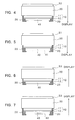
- the present invention provides a transparent laminate formed by laminating high-refractive-index transparent film layers (B) and metal film layers (C) consisting of silver or a silver-containing alloy on one major surface of a transparent substrate (A) in such a way that a repeating unit comprising a combination of one high-refractive-index transparent film layer (B) and one metal film layer (C) in this order is repeatedly laminated three times or more, and further laminating at least a high-refractive-index transparent film layer (B) thereon, wherein the laminated structure composed of the metal film layers and the high-refractive-index transparent film layers constitutes an electrically conductive surface, the electrically conductive surface has a sheet resistance of not greater than 3 ⁇ /sq., and the transparent laminate has a visible light transmittance of not less than 50%, and a light transmittance of not greater than 20% in a wavelength region longer than 820 nm.
- the repeating unit comprising a combination of one high-refractive-index transparent film layer and one metal film layer is typically laminated three times.
- the second metal film layer as numbered from the transparent substrate side is preferably formed so as to be thicker than the first and third metal film layers.
- the transparent laminate of the present invention it is also preferable that, when a transparent tacky material layer or a transparent adhesive layer is laminated on the high-refractive-index transparent film layer remotest from the transparent substrate, the resulting increase in visible light reflectance is not greater than 2%.
- the transparent substrate comprises a transparent polymeric molded material.
- the transparent substrate may contain a dye.
- the high-refractive-index transparent film layers (B) comprise, for example, layers consisting essentially of indium oxide.
- the present invention provides an optical filter for displays comprising the transparent laminate of the present invention. It is preferable that the optical filter for displays of the present invention has a light transmittance of not greater than 10% in a wavelength region longer than 820 nm.
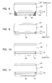
- a metal-containing electrode and/or a transparent protective layer (D) is formed on the electrically conductive surface of the transparent laminate.
- the transparent laminate may be bonded to a transparent molded article (E).
- a transparent protective layer it is preferable that the transparent protective layer has a moisture permeability of not greater than 10 g/m 2 ⁇ day. It is also preferable that the surface of the transparent protective layer is provided with minute irregularities having a size of 0.1 to 10 ⁇ m.
- the transparent protective layer may have antireflection ability. In this case, it is preferable that the surface of the transparent protective layer formed has a visible light reflectance of not greater than 2%.
- the transparent molded article may contain a dye.
- the optical filter for displays of the present invention may be provided with at least one layer selected from an antireflection layer, an antiglare layer and an anti-Newton ring layer.
- a dye-containing transparent molded material (F) may be bonded thereto.
- the transparent laminate of the present invention is one formed by laminating high-refractive-index transparent film layers (B) and film layers consisting of silver or a silver-containing alloy (hereinafter referred to as metal film layers) (C) successively on one major surface of a transparent substrate (A) in such a way that a repeating unit comprising a combination of one high-refractive-index transparent film layer (B) and one metal film layer (C) is repeatedly laminated three times or more, and further laminating at least a high-refractive-index transparent film layer (B) thereon, and having a sheet resistance of not greater than 3 ⁇ /sq., a visible light transmittance of not less than 50%, and a light transmittance of not greater than 20% in a wavelength region longer than 820 nm.
- the transparent substrate (A) may comprise a molded material made of an inorganic compound such as glass or quartz, or a transparent molded material made of an organic polymer.
- Polymeric molded materials can preferably be used because they are light in weight and resistant to breakage. Any desired type of polymeric molded material may be used, provided that it is transparent in the visible wavelength region. Specific examples thereof include, but are not limited to, molded materials made of polyethylene terephthalate (PET), polyethersulfone, polystyrene, polyethylene naphthalate, polyarylate, polyether-ether-ketone (PEEK), polycarbonate, polypropylene, polyimide and triacetylcellulose.
- PET polyethylene terephthalate
- PEEK polyether-ether-ketone
- These transparent polymeric molded materials may be in the form of a plate or film, provided that their major surfaces are smooth.
- a polymeric molded material in plate form is used as the substrate, a transparent laminate having excellent dimensional stability and mechanical strength can be obtained because of the excellent dimensional stability and mechanical strength of the substrate.
- Such a polymeric molded material may preferably be used especially in applications requiring dimensional stability and mechanical strength.
- a transparent polymeric film has flexibility, so that a transparent electrically conductive layer can be continuously formed thereon according to a roll-to-roll process. Consequently, a continuous transparent laminate having a large area can be efficiently produced.
- a transparent laminate in film form can also preferably be used because it may be bonded to the glass screen of a display or the glass support of an optical filter for displays in order to prevent glass pieces from being scattered in thc event of breakage. Tn this cases a polymeric film having a thickness of 10 to 250 ⁇ m is usually used. If the thickness of the film is less than 10 ⁇ m, its mechanical strength is insufficient for use as the substrate. If the thickness is greater than 250 ⁇ m, the film has insufficient flexibility and is not suitable for the purpose of winding it on a roll.
- the surface of the substrate may previously be subjected to etching treatments such as sputtering, corona discharge treatment, flame treatment, ultraviolet ray irradiation and electron beam irradiation, and/or prime coating.
- etching treatments such as sputtering, corona discharge treatment, flame treatment, ultraviolet ray irradiation and electron beam irradiation, and/or prime coating.
- the adhesion between the transparent substrate and the overlying film layer can be enhanced, for example, by forming any desired inorganic material layer between the transparent substrate and the film layer.
- the inorganic material used for this purpose include, but are not limited to, nickel, chromium, gold, silver, platinum, zinc, zirconium, titanium, tungsten, tin, palladium, and alloys composed of two or more of these metals.
- Its thickness may be within limits which do not detract from its transparency, and is preferably in the range of about 0.02 to 10 nm. If the thickness of the inorganic material layer is unduly small, a sufficient adhesion-promoting effect is not produced, while if it is unduly large, its transparency is detracted from.
- the overlying film layer consists of an oxide, all or part of the metal constituting this inorganic material layer is actually converted into a metal oxide. However, even if it is converted into a metal oxide, no influence is exerted on its adhesion-promoting effect.
- the substrate may be subjected to dedusting treatments such as solvent cleaning and ultrasonic cleaning, before the overlying film layer is formed.
- high-refractive-index transparent film layers (B) and metal film layers consisting of silver or a silver-containing alloy (C) are alternately laminated on one major surface of the above-described transparent substrate (A). During this process, each metal film layer (C) is disposed so that it is sandwiched between two high-refractive-index transparent film layers (B).
- Electromagnetic shielding is achieved by the reflection and absorption of electromagnetic waves in an electromagnetic shielding material.
- the electromagnetic shielding material In order to absorb electromagnetic waves, the electromagnetic shielding material must have electric conductivity.
- An electromagnetic shielding material for plasma displays is required to have an electrically conductive layer with very low resistivity.
- the electrically conductive layer must have a thickness above a certain limit in order to absorb all of the electromagnetic waves emerging from displays. In the present invention, however, if the electrically conductive layers (i.e., the metal film layers constituting principal electrically conductive layers) are thickened, the visible light transmittance is reduced in spite of the use of the high-refractive-index transparent film layers. Accordingly, it is important to increase the number of electromagnetic wave-reflecting interfaces by multilayer lamination and thus increase the degree of reflection of electromagnetic waves.
- Shielding effectiveness indicative of electromagnetic shielding characteristics refers to the degree of attenuation of electromagnetic energy, and the magnitude thereof is expressed in decibel (dB).
- Shielding effectiveness (SE) is a parameter of relative evaluation as represented by the following equation (1), and greater values indicate better shielding effects.
- E i incident electric field intensity
- E t transmitted electric field intensity (i.e., the electric field intensity of the electromagnetic waves having passed through the shielding material), and both of them are expressed in V/m.
- SE 20 Log(E i /E t )
- the regulated limit of a leakage electromagnetic field is indicated by an absolute value of radiation field intensity as expressed in dB ⁇ V/m.
- the regulated limit at a position 3 m away from the object of measurement is 50 dB ⁇ V/m in the case of products for industrial use and 40 dB ⁇ V/m in the case of products for domestic use.
- the intensity of the radiation field from a plasma display exceeds 40 dB ⁇ V/m in plasma displays having a diagonal size of about 20 inches, and 50 dB ⁇ V/m in plasma displays having a diagonal size of about 40 inches.
- the radiation field strength of a plasma display for domestic use must be reduced to not greater than 40 dB ⁇ V/m, preferably not greater than 35 dB ⁇ V/m, and more preferably not greater than 30 dB ⁇ V/m.
- the radiation field strength of a plasma display alone is 50 dB ⁇ V/m, it is necessary to provide the plasma display with an electromagnetic shielding material having a shielding effectiveness of not less than 10 dB, preferably not less than 15 dB, and more preferably not less than 20 dB.
- the transparent laminate used as an electromagnetic shielding material must have a large number of electromagnetic wave-reflecting interfaces resulting from multilayer lamination and high electrical conductivity as expressed by a sheet resistance of not greater than 3 ⁇ /sq., preferably not greater than 2.5 ⁇ /sq., and more preferably not greater than 2 ⁇ /sq.
- the electromagnetic shielding material itself has near-infrared cutting-off characteristics. Where a near-infrared absorbing dye is used in combination, the near-infrared cutting-off characteristics required of the electromagnetic shielding material become lower than the above-described performance requirements.
- the transparent laminate used as an electromagnetic shielding material has a light transmittance of not greater than 20% in a wavelength region longer than 820 nm.
- Reflection by free electrons of a metal may be utilized to block near-infrared radiation.
- a thickened metal film layer causes a reduction in visible light transmittance as described above, while a thinned metal film layer weakens the reflection of infrared radiation.
- both the visible light transmittance and the overall thickness of the metal film layers can be increased by superposing two or more laminated structures each formed by sandwiching a metal film layer having a certain thickness between two high-refractive-index transparent film layers.
- the visible light transmittance, visible light reflectance, near-infrared transmittance, transmitted light color and reflected light color can be varied within certain limits by controlling the number of layers and/or the thickness of each layer in this laminated structure.
- an optical filter for displays has a high visible light transmittance which should generally be not less than 50%, preferably not less than 60%, and more preferably not less than 70%. Consequently, the visible light transmittance of the transparent laminate should generally be not less than 50%, preferably not less than 60%, and more preferably not less than 70%.
- a neutral-density (ND) filter may be required to enhance the contrast of the picture.
- the optical filter for displays used as an electromagnetic shielding material also functions as an ND filter.
- the optical filter for displays may be required to have a visible light transmittance of not greater than 80%.
- the color of the light transmitted by the filter greatly influences the contrast of the display, and the like.
- green is unsuitable and neutral gray or neutral blue is required.
- a high visible light reflectance causes lighting equipment and the like to be sharply mirrored in the screen, resulting in reduced visibility.
- the color of the reflected light should preferably be an imperceptible color such as white, blue or purple. Also from this point of view, multilayer lamination which is easy to design and control optically is preferred.
- visible light transmittance and visible light reflectance are values calculated according td JIS (Japanese Industrial Standard) R-3106 on the basis of the wavelength dependence of transmittance and reflectance.
- the metal film layers consist of silver or a silver-containing alloy.
- silver is preferably used because it has high electric conductivity, excellent infrared reflection properties and excellent visible light transmission properties when it is laminated in multiple layers.
- silver lacks chemical and physical stability, so that it tends to deteriorate under the action of contaminants, water vapor, heat, light and other factors present in the environment.
- alloys composed of silver and at least one metal having high environmental stability are also suitable for use in the present invention;
- the content of silver in such a silver-containing alloy it is desirable that the electric conductivity and optical properties thereof do not differ substantially from those of silver alone.
- the content of silver should preferably range from 50% by weight to less than 100% by weight. Since the addition of another metal to silver generally impairs the high electric conductivity and excellent optical properties of silver, it is desirable that, if possible, at least one of the metal film layers constituting the multilayer film is formed of unalloyed silver. When all of the metal film layers are formed of unalloyed silver, the resulting transparent laminate has high electric conductivity and excellent optical properties, but its environmental resistance is not always satisfactory.
- the transparent laminate of the present invention is one characterized by a sheet resistance of not greater than 3 ⁇ /sq., a visible light transmittance of not less than 50%, and a light transmittance of not greater than 20% in a wavelength region longer than 820 nm and at least in the wavelength region of 820 to 1,000 nm.
- This transparent laminate is obtained by laminating high-refractive-index transparent film layers (B) and silver or silver-containing alloy film layers (or metal film layers) (C) on one major surface of a transparent substrate (A) in such a way that a repeating unit comprising a combination of one high-refractive-index transparent film layer (B) and one metal film layer (C) is laminated three times or more, and further laminating at least one high-refractive-index transparent film layer (B) thereon, and has many electromagnetic wave-reflecting interfaces serving for purposes of electromagnetic shielding, a low resistivity, excellent near-infrared cutting-off ability, and very high transparency.
- the repeating unit is preferably laminated three to six times. That is, the preferred layer constructions of the transparent laminate of the present invention are (1) a transparent substrate/a high-refractive-index transparent film layer/a metal film layer/a high-refractive-index transparent film layer/a metal film layer/a high-refractive-index transparent film layer/a metal film layer/a high-refractive-index transparent film layer, (2) a transparent substrate/a high-refractive-index transparent film layer/a metal film layer/a high-refractive-index transparent film layer/a metal film layer/a high-refractive-index transparent film layer/a metal film layer/a high-refractive-index transparent film layer/a metal film layer/a high-refractive-index transparent film layer/a metal film layer/a high-refractive-index transparent film layer, (3) a transparent substrate/a high-refractive-index transparent film layer/a metal film layer/a high-refractive-index transparent film layer/a metal film layer/a high-refractive-index transparent film layer
- the metal film layers consist of silver or a silver-containing alloy. If the repeating unit is laminated twice or less, it is difficult to achieve a low near-infrared transmittance, a low visible light reflectance and a low sheet resistance at the same time. If the repeating unit is laminated seven times or more, severe restrictions are imposed on the production equipment, the problem of productivity becomes serious, and a reduction in visible light transmittance is caused.
- the thicknesses of the metal film layers consisting of silver or a silver-containing alloy can be determined by optical design and experiment, on the basis of their electric conductivity, optical properties and the like. No particular limitation is placed on the thicknesses thereof, provided that the resulting transparent laminate has the required characteristics. However, since it is necessary from the viewpoint of electric conductivity and the like that the metal atoms in the metal film layers are gathered in the form of a continuous film rather than islands, the thicknesses of the metal film layers should desirably be not less than 4 nm. On the other hand, the thicknesses thereof should desirably be not greater than 30 nm, because unduly thick metal film layers will show a reduction in transparency.
- a high-refractive-index transparent film layer adjacent to a metal film layer consists of an oxide
- part of the metal constituting the metal film layer may actually be converted into a metal oxide.
- a metal oxide in the metal film layer forms a very thin region and causes no problem from the viewpoint of optical design and film formation.
- the number (n) of the metal film layers is 3 or more, they do not necessarily have the same thickness.
- the metal film layers do not necessarily have the same composition. That is, according to the order of deposition of the metal film layers, the content of silver therein may be modified, or metals other than silver in alloy may be modified.
- there may be employed any of conventionally known techniques such as sputtering, ion plating, vacuum deposition and metal plating.
- the high-refractive-index transparent film layers (B) are layers which are transparent to visible light and has the effect of preventing the reflection of visible light by the metal film layers owing to the difference in refractive index between the high-refractive-index transparent film layers and the metal film layers.
- No particular limitation is placed on the type of the transparent films constituting the high-refractive-index transparent film layers, provided that the above-described requirements are met.
- a highly refractive material having a refractive index of not less than 1.6 and preferably not less than 1.7 for visible light is usually used.
- the material forming these transparent films include oxides of metals such as indium, titanium, zirconium, bismuth, tin, zinc, antimony, tantalum, cerium, neodymium, lanthanum, thorium, magnesium and gallium; mixtures of these metal oxides; and zinc sulfide.
- the metal and oxygen or sulfur may be present in nonstoichiometric proportions, provided that their optical properties are not substantially modified.
- indium oxide and a mixture of indium oxide and tin oxide (ITO) are preferably used because they not only have high transparency and a high refractive index, but also give a high film formation rate and good adhesion to the metal film layers.
- ITO indium oxide and a mixture of indium oxide and tin oxide
- an oxide semiconductor film e.g., ITO
- the number of electromagnetic wave-absorbing layers can be increased and the electric conductivity of the transparent laminate can be improved.
- each high-refractive-index transparent film layer can be determined by optical design and experiment, on the basis of the optical properties of the transparent substrate, the thicknesses and optical properties of the metal film layers consisting of silver or a silver-containing alloy, the refractive index of the high-refractive-index transparent film layers, and the like. Although no particular limitation is placed on the thickness thereof, it is preferably in the range of 5 to 200 nm and more preferably 10 to 100 nm. When the number (m) of the high-refractive-index transparent film layers is 4 or more, they do not necessarily have the same thickness. Mdreover, the high-refractive-index transparent film layers do not necessarily consist of the same transparent film material. In order to form the high-refractive-index transparent film layers, there may be employed any of conventionally known techniques such as sputtering, ion plating, ion beam assisted deposition, vacuum deposition and wet coating.
- sputtering permits easy control of the film thickness and is hence suitable for use in multilayer lamination.
- the use of sputtering enables the metal film layers consisting of silver or a silver-containing alloy and the high-refractive-index transparent film layers to be formed easily, repeatedly and continuously.
- a procedure for the continuous formation of high-refractive-index transparent film layers consisting essentially of indium oxide and metal film layers consisting of silver or a silver-containing alloy is described below. This procedure will be more fully described in the examples given later.
- High-refractive-index transparent film layers consisting essentially of indium oxide are formed by reactive sputtering using a metal target consisting essentially of indium or a sintered body target consisting essentially of indium oxide.
- a direct-current (DC) or radio-frequency (RF) magnetron sputtering process may be utilized by using an inert gas (e.g., argon) as the sputtering gas, oxygen as the reactive gas, and a pressure usually in the range of 0.1 to 20 mTorr.
- the suitable flow rate of oxygen gas may be experimentally determined on the basis of the resulting film formation rate and the like, and may be controlled so as to form films having a desired degree of transparency.
- Metal film layers consisting of silver or a silver-containing alloy are formed by sputtering using a target consisting of silver or a silver-containing alloy.
- a direct-current (DC) or radio-frequency (RF) magnetron sputtering process may be utilized by using an inert gas (e.g., argon) as the sputtering gas and a pressure usually in the range of 0.1 to 20 mTorr.
- an inert gas e.g., argon
- a hard coat layer having transparency may be disposed on the surface of the transparent substrate (A) opposite to the electrically conductive surface, or any desired protective layer may be disposed on the outermost surface on the side of the electrically conductive surface to such an extent as not to detract from the electric conductivity and optical properties of the transparent laminate.
- the electrically conductive surface is the major surface of the transparent substrate on which the metal film layers and the high-refractive-index transparent film layers are laminated as described above to form a multilayer structure.
- any desired inorganic material layers may be formed between the metal film layers and the high-refractive-index transparent film layers to such an extent as not to detract from the electric conductivity and optical properties of the transparent laminate.
- the inorganic material used for this purpose include copper, nickel, chromium, gold, platinum, zinc, zirconium, titanium, tungsten, tin, palladium, and alloys composed of two or more of these metals.
- the thickness thereof is preferably in the range of about 0.02 to 2 nm. If the thickness is unduly small, a sufficient adhesion-promoting effect is not produced.
- the high-refractive-index transparent film layers consist of an oxide, all or part of the metal constituting these inorganic material layers is actually converted into a metal oxide. However, no influence is exerted on their adhesion-promoting effect.
- a transparent laminate having a higher transmittance can be obtained by disposing any desired monolayer or multilayer antireflection layer on one major surface of the transparent laminate.
- the film material of each layer, the number of layers, the film thicknesses and the like may be determined by optical design according to a vector method using the refractive indices and extinction coefficients of the transparent substrate and the film materials, or a method using an admittance diagram and the like.
- film formation may be carried out by controlling the number of layers, the film thicknesses and the like while observing optical properties.
- a transparent laminate formed by superposing one or more laminated structures comprising a metal film layer sandwiched between high-refractive-index transparent film layers generally tends to undergo changes in optical properties, particularly an increase in visible light reflectance and the accompanying reduction in transparency, if a functional film is bonded to the film-bearing surface through the medium of a tacky material or adhesive, or if a transparent protective layer is formed directly on the film-bearing surface in order to protect the films.
- optical design has been carried out by using a vacuum or air having a refractive index of 1 and an extinction coefficient of 0 as the entrance or exit medium for light entering or leaving the transparent laminate, and observations during film formation have been made under the same conditions.
- the transparent laminate When optical design or film formation has been carried out so that the transparent laminate will have a low visible light reflectance in a vacuum or air, there is obtained a transparent laminate having a low visible light reflectance in the as-made state.
- an adjacent layer such as a transparent tacky material or adhesive or a transparent protective layer is formed on the film-bearing surface, changes in optical properties (in particular, reflectance in the visible wavelength region) are caused.
- the optical properties in particular, refractive index
- the transparent multilayer laminated structure composed of metal film layers and high-refractive-index transparent film layers is referred to as the transparent multilayer film.
- optical design may be carried out by regarding an adjacent layer intended to be formed on the film-bearing surface as the entrance or exit medium for light, and using the refractive index and extinction coefficient of this adjacent layer.
- the adjacent layer comprises a transparent tacky material or adhesive layer or transparent protective layer as described previously, and its thickness is usually not less than 1 ⁇ m and at least 0.5 ⁇ m or greater.
- the adjacent layer has a sufficiently large thickness as compared with the transparent multilayer film, and can hence be regarded as the entrance or exit medium for light.
- the refractive index and extinction coefficient of the material of the transparent tacky material or adhesive layer or transparent protective layer used for this purpose can be measured by using an Abbe refractometer, ellipsometry or the like.
- the refractive indices and extinction coefficients of the high-refractive-index transparent film layers and the metal film layers can be measured by ellipsometry or the like.
- the optical admittance of a laminate is determined on the basis of the optical constants (i.e., refractive index and extinction coefficient) of a transparent substrate, the optical constants and thickness of a film formed on the transparent substrate, the optical constants and thickness of a first film formed thereon, the optical constants and thickness of a second film formed thereon, and so on.
- the interfacial reflection between the entrance or exit medium for light and the transparent film layer can be minimized by designing the optical admittance of the laminate so as to be as close as possible to the optical admittance of the medium.
- optical admittance is numerically equal to complex refractive index N.
- optical design may be carried out with special consideration for optical admittance in this wavelength region.
- a transparent tacky material or adhesive is used.
- a transparent tacky material or adhesive include acrylic adhesives, silicon-based adhesives, urethane adhesives, polyvinyl butyral (PVB) adhesives and ethylene-vinyl acetate (EVA) adhesives; and polyvinyl ether, saturated amorphous polyesters and melamine resins.
- These transparent tacky materials and adhesives have optical properties such as a refractive index of about 1.45 to 1.7 and an extinction coefficient (k) of approximately 0 as measured in the wavelength region of 500 to 600 nm.
- the reflection by the transparent laminate taking its front and back surfaces into consideration i.e., the reflection at both surfaces of the transparent laminate
- the reflection at both surfaces of the transparent substrate/transparent multilayer film/transparent tacky material or adhesive layer does not increase substantially as compared with the reflection by the transparent laminate alone (i.e., the reflection at both surfaces of the transparent substrate/transparent multilayer film).
- the resulting increase in visible light reflectance is not greater than 2% and more preferably not greater than 1%.
- the visible light reflectance does not increase or rather decreases.
- its visible light reflectance remains low even when it is bonded with the aid of a transparent tacky material or adhesive.
- an optical filter for displays having a high visible light transmittance.
- a transparent laminate having an optical admittance close to that of the transparent tacky material or adhesive can be obtained by laminating the high-refractIve-Index transparent film layers (B) and the metal film layers (C) consisting of silver or a silver-containing alloy on one major surface of the transparent substrate (A) in such a way that a repeating unit comprising a combination of one high-refractive-index transparent film layer (B) and one metal film layer (C) is repeatedly laminated three times, and that the second metal film layer as numbered from the transparent substrate side is formed so as to be thicker than the first and third metal film layers.
- a transparent laminate in which, when a transparent tacky material or adhesive layer is formed on the surface of the transparent multilayer film, the resulting increase in visible light reflectance is not greater than 2%.
- the atomic compositions of the high-refractive-index transparent film layers and metal film layers formed in the above-described manner can measured according to a method such as Auger electron spectroscopy (AES), inductively coupled plasma (ICP)-atomic emission spectroscopy or Rutherford backscattering spectrometry (RBS).
- AES Auger electron spectroscopy
- ICP inductively coupled plasma
- RBS Rutherford backscattering spectrometry
- the layer construction and the film thicknesses can be measured by observation in the direction of the depth by Auger electron spectroscopy, by the observation of a cross section under a transmission electron microscope, or the like.
- the film thicknesses are controlled by carrying out film formation on the basis of the previously established relationship between the film-forming conditions and the film formation rate, or by monitoring the film thickness during film formation by means of a quartz oscillator or the like.
- the transparent laminate of the present invention is obtained by laminating a transparent multilayer film on a transparent substrate in the above-described manner.
- the transparent multilayer film has such poor scratch resistance and environmental resistance that, if the film is exposed, it is difficult to use this transparent laminate as an optical filter for displays. Accordingly, it is preferable to form a transparent protective layer (D) on the transparent multilayer film for the purpose of protecting the transparent multilayer film.
- the transparent protective layer (D) as used herein is a layer which is transparent in the visible wavelength region and has the function of protecting the transparent multilayer film.
- the transparent protective layer may comprise, for example, a film having this function; a transparent molded material (e.g., a polymeric film, polymeric sheet or glass sheet) having this function; or a transparent molded material on which a film having this function is formed.
- a transparent molded material e.g., a polymeric film, polymeric sheet or glass sheet
- the transparent protective layer (D) is disposed on the transparent multilayer film formed on the transparent substrate. This may done by forming thereon a film having the function of protecting the transparent multilayer film according to coating, printing or other conventionally known film-forming technique, or by disposing thereon a transparent molded material on which a film having the function of protecting the transparent multilayer film is formed through the medium of any desired transparent tacky material or adhesive. Alternatively, the transparent protective layer may be formed by bonding a transparent molded material having the function of protecting the transparent multilayer film to the transparent laminate through the medium of any desired transparent tacky material or adhesive. No particular limitation is placed on the method for forming the transparent protective layer. Moreover, no particular limitation is placed on the type and thickness of the transparent molded material constituting the transparent protective layer.
- Silver constituting the transparent laminate of the present invention lacks chemical and physical stability, so that it tends to deteriorate under the action of contaminants, water vapor and other factors present in the environment and hence undergo aggregation and whitening. Accordingly, it is important to cover the film-bearing surface of the transparent laminate with a layer having gas barrier properties so that the film may not be exposed to contaminants and water vapor present in the environment. It is preferable that the above-described transparent protective layer (D) has gas barrier properties.
- gas barrier properties are expressed in terms of moisture permeability, the required moisture permeability is not greater than 10 g/m 2 ⁇ day, preferably not greater than 5 g/m 2 ⁇ day, and more preferably not greater than 1 g/m 2 ⁇ day.
- the transparent protective layer having gas barrier properties is a layer which is transparent in the visible wavelength region and has gas barrier properties as defined above.
- This transparent protective layer may comprise, for example, a film having gas barrier properties; a transparent molded material on which a film having gas barrier properties is formed; or a transparent molded material having gas barrier properties.
- a film having gas barrier properties may be formed thereon according to any of various conventionally known film-forming techniques such as chemical vapor deposition (CVD), vacuum deposition, sputtering, ion plating, coating and printing; a polymeric film, polymeric sheet or glass sheet having gas barrier properties may be bonded thereto through the medium of any desired transparent tacky material or adhesive; or a polymeric film or sheet on which a film having gas barrier properties is formed may be bonded thereto through the medium of any desired transparent tacky material or adhesive.
- the transparent tacky material or adhesive used to bond the members to each other may have gas barrier properties. No particular limitation is placed on the method for forming this transparent protective layer having gas barrier properties.
- the film having gas barrier properties include films formed of silicon oxide, aluminum oxide, tin oxide, indium oxide, yttrium oxide, magnesium oxide and mixtures thereof; films formed of such metal oxides having slight amount of other elements added thereto; and films formed of polyvinylidene chloride, acrylic resins, silicon-based resin, melamine resins, urethane resins and fluororesins.
- usable films having gas barrier properties are not necessarily limited thereto.
- the thickness of the film having gas barrier properties is in the range of about 10 to 200 nm for metal oxide films and about 1 to 100 ⁇ m for resin films, and it may have either a monolayer or a multilayer structure. However, it is to be understood that the thickness and structure of the film having gas barrier properties are not limited to those described above.
- Polymeric films having low permeability to water vapor include, for example, films formed of polyethylene, polypropylene, nylon, polyvinylidene chloride, vinylidene chloride/vinyl chloride copolymer, vinylidene chloride/acrylonitrile copolymer and fluororesins.
- moisture permeability is in the range of not greater than 10 g/m 2 ⁇ day, preferably not greater than 5 g/m 2 ⁇ day, and more preferably not greater than 1 g/m 2 ⁇ day.
- a polymeric film has a relatively high moisture permeability, its moisture permeability can be reduced by increasing its thickness or adding a suitable additive thereto. Accordingly, a film formed of polyethylene terephthalate, polycarbonate, polystyrene, polyarylate, polyetheretherketone, polyethersulfone or the like may be used as the transparent protective layer, if it has a sufficient thickness to achieve the above-described moisture permeability.
- an optical filter for displays in accordance with the present invention is used as a shield against electromagnetic waves
- the transparent protective layer it is important to take care that the transparent protective layer does not prevent electrical connection between the metal-containing electrode formed on the electrically conductive surface of the optical filter for displays and the main body of the display. That is, the transparent protective layer should be formed so as to cover all of the film-bearing surface except the region on which the electrode is formed.
- the deterioration of the metal film layers consisting of silver or a silver-containing alloy can also be inhibited by dissolving a compound capable of inhibiting the deterioration of silver and silver-containing alloys in any suitable solvent and applying this solution to the film-bearing surface and side faces of the transparent laminate.
- any desired transparent tacky material or adhesive may be used to bond the members constituting the transparent laminate or optical filter for displays to each other.
- the tacky material or adhesive used in the central part through which light from the display passes must be transparent to visible light.
- the tacky material or adhesive may be in sheet or liquid form, provided that it has a bond strength sufficient for practical purposes.
- a pressure-sensitive adhesive in sheet form is preferably used as the tacky material. Lamination is carried out by superposing members after the application of a tacky material in sheet form or an adhesive in liquid form.
- the adhesive in liquid form is an adhesive which, after it is applied to a member and another member is superposed thereon, is cured by allowing the assembly to stand at room temperature or by heating the assembly.
- the adhesive may be applied by any of various techniques such as bar coating, reverse coating, gravure coating, die coating and roll coating, the application technique is usually chosen with consideration for the type and viscosity of the adhesive, the amount of adhesive used, and the like. Although no particular limitation is placed on the thickness of the tacky material or adhesive layer, it is typically in the range of 0.5 to 50 ⁇ m and preferably 1 to 30 ⁇ m. After members are bonded with the aid of a tacky material or adhesive, the assembly is preferably kept under high-pressure and elevated-temperature conditions in order to remove any air entrapped between the members during bonding or dissolve it in the tacky material or adhesive and, moreover, improve the adhesion between the members.
- the high pressure used for this purpose is typically in the range of several to 20 atmospheres.
- the elevated temperature typically ranges from room temperature to 80 °C, though it depends on the thermal resistance of each member. However, it is to be understood that the high-pressure and elevated-temperature conditions are not necessarily limited thereto.
- a transparent tacky material or adhesive having gas barrier properties as expressed by a moisture permeability of not greater than 10 g/m 2 ⁇ day, preferably not greater than 5 g/m 2 ⁇ day, and more preferably not greater than 1 g/m 2 ⁇ day when measured with the tacky material or adhesive alone or the laminate of the tacky material or adhesive and the film.
- electromagnetic waves are blocked by disposing a metal layer within the case of the equipment or by using a case made of an electrically conductive material.
- a window-like optical member having a transparent electrically conductive layer formed thereon i.e., an optical filter for displays
- electromagnetic waves absorbed in the electrically conductive layer induces electric charge, this electric charge must be allowed to escape by grounding the electrically conductive layer. Otherwise the electromagnetic shielding material acts as an antenna for emitting electromagnetic waves, resulting in a reduction in electromagnetic shielding power.
- the optical filter for displays of the present invention should preferably be ohmically connected to an electrically conductive part within the case for the main body of the display.
- part of the surface of transparent multilayer film constituting the electrically conductive part of the transparent laminate is exposed. Consequently, the various layers overlying the surface of the transparent multilayer film, including the above-described transparent protective layer, must be formed except the part in which electrical contact is made.
- the metal-containing electrode is continuously formed on a peripheral region of the electrically conductive surface of the transparent laminate (i.e., the surface of the transparent multilayer film). That is, the metal-containing electrode is formed thereon in the form of a frame and without surface irregularities, except for the central region through which light from the display passes.
- the electrode has the function of allowing the electric charge induced by electromagnetic waves absorbed in the electrically conductive layer to escape efficiently to the interior of the case for the main body of the display.
- FIG. 1 is a plan view of an optical filter for displays having such an electrode in accordance with a preferred embodiment of the present invention.
- a transparent laminate 10 is formed on a transparent molded article 30, and an electrode 20 in the shape of a rectangular frame is formed on the surface of transparent laminate 10.
- Electrode 20 is disposed along the periphery of transparent laminate 10.
- the shape of the electrode is not limited to that illustrated in FIG. 1.
- the transparent electrically conductive layer (or transparent multilayer film) of the transparent laminate, the metal-containing electrode, and the electrically conductive layer within the case of the display main body differ greatly in resistivity, an impedance difference exists at the contact parts thereof, and electromagnetic waves are emitted from these contact parts.
- the electrically conductive layer within the case comprising a metal layer and hence has a resistivity of not greater than 10 -5 ⁇ cm, while the transparent electrically conductive layer has a resistivity of 10 -5 to 10 -4 ⁇ cm or greater.
- the electrode disposed on the electrically conductive surface of the transparent laminate has a resistivity of not greater than 1 ⁇ 10 -3 ⁇ cm.
- the materials which can be used for the electrode include metals such as silver, gold, copper, platinum, nickel, aluminum, chromium, iron, zinc, and alloys composed of two or more of these metals; and silver pastes comprising a mixture of a synthetic resin and silver or a silver- containing alloy, or a mixture of borosilicate glass and silver or a silver-containing alloy.
- the electrode can be formed according to any of various conventionally known techniques such as metal plating, vacuum deposition and sputtering.
- additional techniques such as printing and coating may also be employed.
- the thickness of the metal-containing electrode it typically ranges from several micrometers to several millimeters.
- the transparent electrically conductive layer i.e., the transparent multilayer film
- the transparent electrically conductive layer constituting a current flow path is exposed in the part of this optical filter for displays which comes into contact with the main body of the display. Since the films used in the transparent electrically conductive layer have poor scratch resistance and environmental resistance as described above, the transparent electrically conductive layer exposed in the part for electrical contact with the main body of the display leads to a reduction in reliability and the like. Accordingly, when the transparent laminate is used as an optical filter for displays, it is important that the transparent electrically conductive layer is not exposed but has an electrode formed thereon.
- this electrode serves as a protective layer for the transparent electrically conductive layer and can impart scratch resistance and environmental resistance thereto. Accordingly, it is desirable that the whole surface of the transparent electrically conductive layer is covered with the transparent protective layer or the electrode. If there is a part on which neither of them is formed, contaminants and water vapor present in the environment may invade the transparent electrically conductive layer through that part, resulting in a whitening of the metal film layers.
- the transparent substrate (A) it is desirable from the viewpoint of strength, planarity during use on a display, mounting method and the like that the transparent laminate formed in the above-described manner is bonded to a transparent mdlded article (E) in the form of a plate having smooth major surfaces.
- a transparent mdlded article (E) in the form of a plate having smooth major surfaces.
- any desired major surface of the transparent laminate may be bonded to the transparent molded article.
- the film-bearing surface of the transparent laminate is bonded to a major surface of the transparent molded article (E)
- at least one of the transparent tacky material or adhesive and the transparent molded article (E) may serves as a transparent protective layer for the transparent laminate.
- a plastic plate which is transparent in the visible light region is preferred because of its high mechanical strength, light weight and resistance to breakage.
- a glass plate is also preferred in view of thermal stability because the glass plate has small heat deflection properties.
- Specific examples of the material of the plastic plate include, but are not limited to, acrylic resins such as polymethyl methacrylate (PMMA), polycarbonate resins and transparent ABS resins.
- PMMA can preferably be used because it is highly transparent over a wide wavelength range and has high mechanical strength.
- No particular limitation is placed on the thickness of the plastic plate used as the transparent molded article, provided that sufficient mechanical strength and sufficient rigidity to keep it flat without deflection are secured. However, its thickness is usually in the range of about 1 to 10 mm.
- the optical filter for displays is used by mounting it in contact with the screen of a display
- the degree of contact between the display screen and the optical filter for displays may vary from part to part, and the resulting gaps may produce Newton rings.
- this anti-Newton ring layer must not hinder the contact between the metal-containing electrode and the main body of the display.
- the optical filter for displays with an antireflection layer for suppressing the reflection of external light or an antiglare layer for imparting antiglare properties thereto.
- This antireflection layer or antiglare layer is formed on the major surface of the optical filter for displays which faces the user when it is mounted on the display, i.e., the major surface thereof opposite to the main body of the display.
- the reflection of external light by the optical filter for displays can further be reduced by forming an antireflection layer on the major surface of the optical filter for displays which faces the main body of the display when it is mounted on the display.
- the antiglare layer and the antireflection layer are formed on the side of the electrically conductive surface of the transparent laminate, they must be disposed so as not to hinder the electrical contact between the metal-containing electrode and the optical filter for displays.
- the anti-Newton ring layer, antiglare layer and antireflection layer each refer to a film having the corresponding function, or a molded material on which a film having the corresponding function is formed.
- Each of these anti-Newton ring layer, antiglare layer and antireflection layer may be formed by forming a film having the desired function on the desired substrate according to coating, printing or other conventionally known film-forming technique, by bonding thereto a transparent molded material on which a film having the desired function is formed, or a transparent molded material having the desired function through the medium of any desired transparent tacky material or adhesive.
- No particular limitation is placed on the method for forming the anti-Newton ring layer, antiglare layer and antireflection layer.
- no particular limitation is placed on the type and thickness of the transparent molded material used for this purpose.
- the transparent protective layer has such properties. In this case, it is unnecessary to form an anti-Newton ring layer, an antiglare layer or an antireflection layer on the transparent protective layer. Conversely, it is also preferable that the anti-Newton ring layer, the antiglare layer or the antireflection layer has the functions of the transparent protective layer, i.e., scratch resistance and gas barrier properties.
- the elements constituting the antireflection film and the film thickness of each element may be determined by carrying out the above-described optical design with consideration for the optical properties of the substrate on which this antireflection layer is formed.
- the performance of the antireflection layer should desirably be such that the antireflection film-bearing surface thereof has a visible light reflectance of not greater than 2%, preferably not greater than 1.5%, and more preferably not greater than 0.5%.
- the visible light reflectance of the antireflection film-bearing surface can be determined by measuring only the reflection occurring at the antireflection film-bearing surface after the reflection occurring at the opposite surface (i.e., the surface on which no antireflection film is formed) has been canceled, for example, by roughening the opposite surface with sand paper and painting it in black.
- the antireflection film may comprise a single-layer film formed of a material having a low refractive index of not greater than 1.5 and preferably not greater than 1.4 in the visible light region (e.g., a fluorine-containing transparent polymeric resin, magnesium fluoride, silicon-based resin or silicon oxide) so as to have, for example, a quarter-wavelength optical thickness.
- a material having a low refractive index of not greater than 1.5 and preferably not greater than 1.4 in the visible light region e.g., a fluorine-containing transparent polymeric resin, magnesium fluoride, silicon-based resin or silicon oxide
- the antireflection film may also be formed by laminating two or more films consisting of inorganid compounds (e.g., metal oxides, fluorides, silicides, borides, carbides, nitrides or sulfides) or organic compounds (e.g., silicon-based resin, acrylic resins or fluororesins) and having different refractive indices.
- inorganid compounds e.g., metal oxides, fluorides, silicides, borides, carbides, nitrides or sulfides
- organic compounds e.g., silicon-based resin, acrylic resins or fluororesins
- Single-layer antireflection films are easier to form, but are inferior to multilayer ones in antireflection properties.
- Multilayer antireflection films have antireflection properties over a wide wavelength range and are subject to less restriction in optical design based on the optical properties of the substrate.
- Inorganic compound films serving as antireflection films may be formed by any of conventionally known techniques such as sputtering, ion plating, ion beam assisted deposition, vacuum deposition and wet coating.
- Organic compound films serving as antireflection films may be formed by any of conventionally known techniques such as wet coating.
- the antireflection layer formed on the film-bearing surface of the transparent laminate i.e., the antireflection film, the transparent molded material on which the antireflection film is formed, or the transparent molded material having antireflection properties
- this antireflection layer include polyethylene terephthalate films or fluororesin films on which a single layer of silicon oxide or a fluororesin is formed to a quarter-wavelength optical thickness. These films have low permeability to water vapor and good antireflection properties. Moreover, scratch resistance can be imparted thereto by forming them on the transparent multilayer film.
- the anti-Newton ring layer and the antiglare layer are both layers which are transparent to visible light and are provided with minute surface irregularities having a size of about 0.1 to 10 ⁇ m, except that they differ in purpose.
- the anti-Newton ring layer has antiglare properties.
- the anti-Newton ring layer and the antiglare layer are formed by dispersing particles of an inorganic or organic compound (e.g., silica, a melamine resin or an acrylic resin) in a heat-curable or photo-curable resin (e.g., an acrylic resin, silicon-based resin, melamine resin, urethane resin, alkyd resin or fluororesin) to prepare an ink, applying this ink to the substrate according to a technique such as bar coating, reverse coating, gravure coating, die coating or roll coating, and the curing the ink.
- the average diameter of the particles may be, for example, in the range of 1 to 40 ⁇ m.
- the anti-Newton ring layer and the antiglare layer may also be formed by coating a substrate with a heat-curable or photo-curable resin (e.g., an acrylic resin, silicon-based resin, melamine resin, urethane resin, alkyd resin or fluororesin), pressing the coated substrate against a mold having a desired haze or surface state, and then curing the resin.
- a heat-curable or photo-curable resin e.g., an acrylic resin, silicon-based resin, melamine resin, urethane resin, alkyd resin or fluororesin
- the antiglare layer may also be formed by treating a substrate with a chemical agent (e.g., by etching a glass sheet with hydrofluoric acid). In this case, the haze of the antiglare layer can be controlled according to the treating time and the etching properties of the chemical agent.
- the anti-Newton ring layer and the antiglare layer should generally have a haze of 0.5 to 20% and preferably 1 to 10%. If the haze is unduly low, they have insufficient antiglare ability or anti-Newton ability. If the haze is unduly high, the transmittance of parallel rays is reduced, resulting in poor visibility of the display.
- a layer comprising a film having such properties, a transparent molded material on which a film having such properties is formed, or a transparent molded material having such properties is disposed thereon. If the aforesaid layer has gas barrier properties, this is preferable in that the number of members can be decreased.
- a transparent protective layer in which particles of an inorganic or organic compound as described above is dispersed to impart anti-Newton ring properties and/or antiglare properties thereto.
- this polyethylene terephthalate film may be bonded to the film-bearing surface with the aid of a transparent tacky material or adhesive. Moreover, scratch resistance can be imparted thereto by forming it on the transparent multilayer film.
- the antiglare layer of the optical filter for displays lies a little away from the surface of the display.
- the antiglare layer may cause the diffusion of the picture, resulting in a blur thereof.
- the surfaces thereof may be provided with a hard coat layer having at least such a degree of transparency as not to impair the properties (in particular, optical properties) of the optical filter for displays.
- the antiglare layer may function as a hard coat layer, or the antireflection layer may function as a hard coat layer.
- the transparent multilayer film-bearing surface of the transparent laminate is required to have hard coat properties, it is preferable to impart hard coat properties to the transparent protective layer.
- the surface of a display tends to attract dust owing to electrostatic charge and, moreover, such static electricity may be discharged upon contact with a human body to give an electric shock thereto. Accordingly, it may be required to subject the display to an antistatic treatment.
- the problem of electrostatic charge can be solved by forming an electrically conductive layer directly on the surface of the display or bonding a member having an electrically conductive layer to the surface of the display, and grounding these electrically conductive layers. Accordingly, in order to impart antistatic properties to the optical filter for displays, an electrically conductive layer may be formed on the user-side surface (i.e., the surface opposite to the display when the optical filter is mounted on the display).
- the electrically conductive layer used for this purpose may be one which has a sheet resistance of about 10 8 ⁇ /sq. or less and does not detract from the transparency or resolution of the display screen.
- This electrically conductive layer may comprise a transparent electrically conductive film.
- a transparent electrically conductive layer for antistatic use may be formed in any of the following manners. That is, (1) a transparent electrically conductive layer is formed on the antiglare layer, or (2) electrical conductivity is imparted to the antireflection layer or the antiglare layer.
- a transparent electrically conductive layer for antistatic use is provided by forming a well-known transparent electrically conductive film consisting, for example, of ITO in the previously described manner, or bonding a polymeric film on which an ITO film is previously formed. In this case, it is important that the formation of a transparent electrically conductive layer for antistatic use does not detract substantially from the antiglare properties.
- a transparent electrically conductive layer for antistatic use is formed on the antiglare layer, a thin film which does not detract from its antiglare properties may be effectively used because the electrical conductivity required for antistatic purposes is relatively low.
- electrically conductive ultrafine particles such as ultrafine particles of ITO or tin oxide may be dispersed in the antiglare layer.
- electrical conductivity is imparted to the antireflection layer, this may be done by carrying out the optical design of the antireflection layer while considering a transparent electrically conductive film to be a constituent element thereof.
- Specific examples of such an antireflection layer include one composed of substrate/ITO/silicon-containing compound/ITO/silicon-containing compound and one composed of substrate/ITO/fluorine-containing compound.
- the transparent laminate of the present invention has, in addition to electromagnetic shielding characteristics, near-infrared cutting-off characteristics.
- a near-infrared absorbing dye may be used in combination to supplement the near-infrared cutting-off characteristics of the transparent laminate.
- optical filters for displays have a transmitted light color such as neutral gray or neutral blue. Accordingly, in order to control the color tone of the laminate and thereby obtain an optical filter for displays having a transmitted light color as described above, a commercially available dye having an absorption band in the visible light region may be used in combination as a toning dye.
- a dye may be contained by (1) containing the dye in the transparent substrate of the transparent laminate, (2) containing the dye in any one of the transparent molded article, transparent protective layer, antireflection layer, antiglare layer, anti-Newton ring layer and hard coat layer which are bonded to or formed on the transparent laminate, (3) containing the dye in any one of the transparent tacky material or adhesive layers used for bonding purposes, or (4) bonding, as one constituent element of the optical filter for displays, a dye-containing transparent molded material (F) between any two members constituting the optical filter for displays, with the aid of any desired tacky material or adhesive.
- F transparent molded material
- the optical filter for displays containing a dye therein has excellent near-infrared cutting-off characteristics owing to the supplementation of the near-infrared cutting-off ability associated with the films when the dye is a near-infrared absorbing dye, or has an excellent color tone of transmitted light when the dye is a toning dye.
- the term "dye” means a toning dye having an absorption band in the visible light region or a near-infrared absorbing dye having an absorption band in the near-infrared wavelength region.
- the type of the near-infrared absorbing dye used in the present invention provided that it can supplement the near-infrared cutting-off characteristics of the laminate and can absorb intense near-infrared radiation emerging from plasma displays to such an extent as to be suitable for practical purposes.
- the concentration of the near-infrared absorbing dye is placed that it is within the limits which do not affect the visible light transmittance to such an extent as to be suitable for practical purposes.
- the optical filter for displays of the present invention can have more excellent near-infrared cutting-off characteristics.
- Compounds of the following general formulae (1) and (2) are on the market and readily available.
- a 1 to A 8 each independently represent a hydrogen atom, a halogen atom, a nitro group, a cyano group, a thiocyanate group, a cyanate group, an acyl group, a carbamoyl group, an alkylaminocarbonyl group, an alkoxycarbonyl group, an aryloxycarbonyl group, a substituted or unsubstituted alkyl group, a substituted or unsubstituted aryl group, a substituted or unsubstituted alkoxy group, a substituted or unsubstituted aryloxy group, a substituted or unsubstituted alkylthio group, a substituted or unsubstituted arylthio group, a substituted or unsubstituted alkylamino group, or a substituted or unsubstituted arylamino group, or any two adjacent substituents may be joined through the medium of a connecting group;
- B 1 to B 4 each independently represent a hydrogen atom, a cyano group, an acyl group, a carbamoyl group, an alkylaminocarbonyl group, an alkoxycarbonyl group, an aryloxycarbonyl group, a substituted or unsubstituted alkyl group, or a substituted or unsubstituted aryl group, or any two adjacent substituents may be joined together through the medium of a connecting group; and M represents nickel, platinum, palladium or copper.
- the term "contain” means not only the state of a dye contained in the interior of a base material, but also the state of a dye coated on a surface of a base material, the state of a dye sandwiched between base materials, and the like.
- the base material may comprise any of the transparent substrate (A) of the transparent laminate, the transparent molded article (E) to which the transparent laminate is bonded, the transparent protective layer (D), the antireflection layer, the antiglare layer, the anti-Newton ring layer and the hard coat layer, or the transparent molded material (F) which is used to contain a dye and is contained in an optical filter for displays.
- a film having the corresponding function may contain a dye, or a film having the corresponding function may be formed on a dye-containing transparent molded material.
- the dye-containing transparent molded material may comprise a transparent plastic plate, a transparent polymeric film, a glass sheet or the like. As described above, the content of the dye depends on the optical properties of the transparent laminate and the optical properties required of the optical filter for displays.
- a resin material which has as high transparency as possible when formed into a plate or film.
- resin material which has as high transparency as possible when formed into a plate or film.
- Specific examples thereof include, but are not limited to, vinyl compounds and addition polymers thereof, such as polyethylene, polystyrene, polyacrylic acid, polyacrylates, polyacrylonitrile, polyvinyl acetate, polyvinyl chloride and polyvinyl fluoride; polymethacrylic acid, polymethacrylate, polyvinylidene chloride, polyvinylidene fluoride, polyvinylidene cyanide; copolymers of vinyl compounds or fluorine-containing compounds, such as vinylidene fluoride/trifluoroethylene copolymer, vinylidene fluoride/tetrafluoroethylene copolymer and vinylidene cyanide/vinyl acetate copolymer; fluorine-containing compounds such as polytriflu
- the processing temperature, film-forming conditions and the like may vary somewhat according to the dye used and the polymeric molded article constituting the base.
- there may usually employed (i) a method in which a dye is added to a powder or pellets for the making of a polymeric molded article constituting the base, and the resulting blend is melted at 150 - 350 °C and formed into a resin plate; (ii) a method in which a film is extruded by means of an extruder; or (iii) a method in which a raw film is extruded by means of an extruder and then uniaxially or biaxially stretched 2- to 5-fold at 30-120 °C to form a film having a thickness of 10 to 200 ⁇ m.
- Additives commonly used in the molding of resins such as ultraviolet absorbers and plasticizers, may be added during kneading.
- the amount of dye added may vary according to the absorption coefficient of the dye, the thickness of the polymeric molded article being made, the desired absorptivity, the desired visible light transmittance and the like, it usually ranges from 1 ppm to 20% by weight.
- Specific examples of the method (2) which comprises preparing a coating composition and coating it include a method in which a dye is dissolved in a binder resin and an organic solvent to prepare a coating composition, and a method in which a dye is pulverized to a particle size of several micrometers or less and dispersed in an acrylic emulsion to prepare an aqueous coating composition.
- a resin selected from aliphatic ester resins, acrylic resins, melamine resins, urethane resins, aromatic ester resins, polycarbonate resins, aliphatic polyolefin resins, aromatic polyolefin resins, polyvinyl resins, polyvinyl alcohol resin, modified polyvinyl resins (e.g., PVB and EVA) and copolymer resins thereof is usually used as the binder resin.
- a solvent selected from halogenated hydrocarbons, alcohols, ketones, esters, aliphatic hydrocarbons, aromatic hydrocarbons, ethers and mixtures thereof.
- the concentration of the dye may vary according to the absorption coefficient of the dye, the thickness of the coating, the desired absorptivity, the desired visible light transmittance and the like, it is usually in the range of 0.1 to 30% by weight based on the weight of the binder resin.
- the concentration of the binder resin is usually in the range of 1 to 50% by weight based on the total weight of the coating composition.
- An acrylic emulsion-based aqueous coating composition may similarly be prepared by dispersing a pulverized dye (having a particle size of 50 to 500 nm) in an uncolored acrylic emulsion coating material.
- Additives commonly used in coating compositions, such as ultraviolet absorbers and antioxidants, may be added to the above coating composition.
- the coating composition prepared according to any of the above-described method is coated on a transparent polymeric film, a transparent resin plate, a glass sheet or the like by means of a bar coater, a blade coater, a spin coater, a reverse coater, a die coater, a spray gun or the like.
- a dye-containing base material there is obtained.
- a protective layer may be formed on the coated surface, or a transparent resin plate, a transparent polymeric film or the like may be bonded to the coated surface.
- cast films are also within the scope of this method.
- the method (3) which comprises incorporating a dye into an adhesive and using it to make a composite resin plate, a composite resin film, a glass laminate or the like
- resins such as silicon-based, urethane and acrylic adhesives
- transparent adhesives for glass laminates such as polyvinyl butyral (PVB) adhesives and ethylene-vinyl acetate (EVA) adhesives.
- PVB polyvinyl butyral
- EVA ethylene-vinyl acetate
- the aforesaid adhesive containing a dye may be used to bond various members such as the transparent laminate, the transparent molded article (E) to which the transparent laminate is bonded, the transparent protective layer (D), the antireflection layer, the antiglare layer, the anti-Newton ring layer and the dye-containing transparent molded material (F).
- optical filters for plasma displays are required to block intense near-infrared radiation from plasma displays in the wavelength region of 800 to 1,000 nm. If it is necessary for this purpose, two or more dithiol complex compounds of the above general formulae (1) and/or (2) may be used in combination. If desired, one or more other near-infrared absorbing dyes may be added thereto. Furthermore, in order to obtain an optical filter for displays having a desired color tone in addition to near-infrared blocking ability, one or more toning dyes having an absorption band in the visible light region may be added thereto.
- a transparent film containing a UV absorber i.e., a UV cutoff filter
- a UV absorber i.e., a UV cutoff filter
- optical filters for displays in accordance with the present invention may be modified as required.
- the transparent laminates and optical filters for displays of the present invention have excellent near-infrared blocking ability.
- the optical filters for displays of the present invention are less liable to deterioration by environmental factors such as humidity, heat and light, as compared with near-infrared cutting-off filters using common organic dyes alone to block near-infrared radiation.
- dithiol complex compounds of the above general formulae (1) and (2) have excellent environmental resistance, optical filters for displays which are less liable to deterioration can also be obtained when such a compound or a mixture of such compounds is used as a dye.
- the transparent laminates and optical filters for displays of the present invention can preferably be used as near-infrared cutting-off filters.
- FIG. 2 illustrates a transparent laminate 10 in accordance with a preferred embodiment of the present invention.
- This transparent laminate 10 comprises a transparent substrate 11 consisting of a polymeric film or the like, and a transparent electrically conductive layer (i.e., transparent multilayer film) 12 disposed on one major surface of transparent substrate 11.
- Transparent electrically conductive layer 12 is formed by laminating four high-refractive-index transparent film layers 13 and three metal film layers 14 alternately on the major surface of transparent substrate 11.
- high-refractive-index transparent film layers 13 consist essentially of indium oxide.
- Metal film layers 14 consist of silver or a silver-containing alloy. In the illustrated transparent laminate 10, the three metal film layers 14 are formed in such a way that the middle metal film layer 14 is thicker than the other metal film layers 14.
- FIG. 3 illustrates an optical filter for displays in accordance with a preferred embodiment of the present invention, which is made by using transparent laminate 10 illustrated in FIG. 2.
- the major surface of transparent laminate 10 opposite to transparent electrically conductive layer 12 is bonded to one major surface of a transparent molded article 30.
- an antireflection layer 51 comprising an antireflection film.
- an electrode 20 is formed so as to cover the side faces of transparent electrically conductive layer 12.
- Electrode 20 contains a metal and serves to ground transparent electrically conductive layer 12.
- the two-dimensional shape of electrode 20 is as shown in FIG. 1.
- a plasma display on which this optical filter for displays is to be mounted is provided on a peripheral region of the screen with an electrically conductive layer for grounding purposes, the electrically conductive layer of the plasma display comes into electrical contact with electrode 20 of the optical filter for displays when the optical filter for displays is mounted on the plasma display, so that the grounding of transparent electrically conductive layer 12 is effected.
- the optical filter for displays and the screen of the display are electrically connected without leaving any space therebetween, so that a marked reduction in leakage electromagnetic waves can be achieved.
- transparent electrically conductive layer 12 it is important that no space is left between the part of transparent electrically conductive layer 12 covered with transparent protective layer 40 and the part of transparent electrically conductive layer 12 covered with electrode 20.
- the optical filters for displays of the present invention can be broadly classified into the following four types. However, it is to be understood that the present invention is not limited thereto.
- the optical filter for displays in which the transparent protective layer functions as an anti-Newton ring layer is usually mounted on the display so that the electrode of the filter faces the display.
- an optical filter for displays as shown in FIG. 3 it is composed of (metal-containing electrode 20 and transparent protective layer 40)/transparent laminate 10/transparent molded article 30/antireflection layer 51 in that order as viewed from the display side.
- antireflection layer 51 may be replaced by an antiglare layer 52 as shown in FIG. 4.
- the optical filter for displays is composed of (electrode 20 and anti-Newton ring layer 41)/transparent protective layer 40/transparent laminate 10/transparent molded article 30/antireflection layer 51 in that order as viewed from the display side.
- antireflection layer 51 may be replaced by an antiglare layer 52.
- the optical filter for displays is composed as shown in FIG. 6 so that it consists of anti-Newton ring layer 53/transparent molded article 30/transparent laminate 10/(transparent protective layer 40 and metal-containing electrode 20) in that order as viewed from the display side. If transparent protective layer 40 does not function as an antiglare layer or an antireflection layer, the optical filter for displays is composed as shown in FIG.
- antireflection layer 42 may be replaced by an antiglare layer 43 as shown in FIG. 8.
- the optical filter for displays is not brought into contact with the surface of the screen of the display. As a result, it is unnecessary to form an anti-Newton ring layer or cause the transparent protective layer to function as an anti-Newton ring properties. Instead, it is necessary to impart antireflection properties or antiglare properties to both major surfaces of the optical filter for displays.
- the optical filter for displays is composed as shown in FIG. 3 or 4. However, it depends on the position of an electrically conductive layer for grounding purposes to decide which major surface of the optical filter for displays is made to face the display. If transparent protective layer 40 does not function as an antireflection layer or an antiglare layer, anti-Newton ring layer 53 may be replaced by an antireflection layer 51 or an antiglare layer 52 in the optical filters for displays shown in FIGs. 7 and 8.' However, it may be arbitrarily decided which major surface of the optical filter for displays is made to face the display.
- the optical filter for displays need not have an electrode. If the transparent protective layer functions as an anti-Newton ring layer, the optical filter for displays is composed as shown in FIG. 9 so that it consists of transparent protective layer 40/transparent laminate 10/transparent molded article 30/antireflection layer 51 in that order as viewed from the display side. Antireflection layer 51 may be replaced by an antiglare layer 52. If the transparent protective layer does not function as an anti-Newton ring layer, an anti-Newton ring layer 41 is bonded to transparent protective layer 40 as shown in FIG. 10. In either case, transparent protective layer 40 is formed so as to cover the whole surface of transparent laminate 10, including the side faces thereof.
- the optical filter for displays is usually composed of (antireflection layer or antiglare layer)/transparent laminate/transparent molded article/(antireflection layer or antiglare layer) in that order.
- the dye(s) may be incorporated into any one or more of the above-described elements constituting the optical filters, or a transparent molded material containing the dye(s) may be sandwiched between any adjacent ones of the above-described elements.
- the transparent protective layer functions as an antireflection layer or an antiglare layer in the aforesaid type (2)
- the optical filter for displays is composed of (metal electrode and transparent protective layer)/transparent laminate/transparent molded article/dye-containing transparent molded material/(antireflection layer or antiglare layer) in that order as viewed from the display side.
- a film having antireflection properties or antiglare properties may be formed directly on the dye-containing transparent molded material, or a film having such a function may be bonded thereto.
- the optical filter for displays may be warped. Accordingly, it is essential to bond them so as not to cause warpage.
- a polymeric film is bonded, it is important to bond it while balancing the forces (such as film tensions) exerted on the transparent molded article with respect to both surfaces, and not only one surface, thereof. When no bonding is made, it is important that the transparent molded article is not warped.
- the optical filter for displays mounted on a display is warped toward the user, the visibility of the image is reduced. Moreover, when the optical filter for displays has an antiglare layer, a blur of the image may be caused.
- the anti-Newton ring layer usually has antiglare properties.
- this optical filter for displays may be used by bringing any desired side thereof into contact with the surface of the display screen.
- an anti-Newton ring layer is formed on either side of the optical filter for displays.
- FIG. 11 illustrates an example of such an optical filter for displays.
- a first anti-Newton ring layer 41, a transparent protective layer 40, a transparent laminate 10, a transparent molded article 30 and a second anti-Newton ring layer 53 are laminated in that order.
- the optical filters for displays of the present invention may be subjected to any desired frame printing in order that, when they are mounted on displays, the mounting assembly, the electrode and the like will be invisible to the user. No particular limitation is placed on the shape, surface, color and method employed for this frame printing. Moreover, they may further be worked, for example, to make holes for mounting them on displays. Furthermore, if they are provided with a polarizing film, a phase-difference film or the like to impart thereto the function of a circularly polarizing filter, they can further suppress reflected light from the display side and provide more excellent optical filters.
- the optical filters for displays of the present invention have a high visible light transmittance, they do not detract from the definition of displays and have excellent electromagnetic shielding characteristics for blocking electromagnetic waves emitted from displays and considered to be harmful to health. Moreover, since they efficiently cut off near-infrared radiation, in the wavelength region of about 800 to 1,000 nm, emerging from plasma displays, they exert no adverse influence on wavelengths used in optical communication by transmission systems or the like, and can hence prevent the malfunction of infrared remote controllers for electronic equipment in the neighborhood thereof. Furthermore, they have good weather resistance and environmental resistance, as well as antireflection properties, antiglare properties and/or anti-Newton ring properties.
- the present invention is further illustrated by the following examples. However, these examples are not to be construed to limit the scope of the invention.
- the film thicknesses given in the following examples and comparative examples are values obtained from the relationship between the film thickness and the film-forming time as determined previously under the same film-forming conditions, and are not values obtained by actually measuring the thicknesses of the films formed in these examples and comparative examples.
- an ITO film (40 nm thick), a silver film (10 nm thick), an ITO film (80 nm thick), a silver film (15 nm thick), an ITO film (80 nm thick), a silver film (10 nm thick) and an ITO film (40 nm thick) were laminated, in that order, on one major surface of a biaxially stretched polyethylene terephthalate film (50 ⁇ m thick).
- a transparent laminate in accordance with the present invention having three metal film layers and four high-refractive-index transparent film layers, was formed.
- the ITO films constituted the high-refractive-index transparent film layers, and the silver films constituted the metal film layers.
- the ITO films were formed by using an indium oxide/tin oxide sintered body [composed of In 2 O 3 and SnO 2 in a ratio of 90:10 (wt.%)] as the target and an argon-oxygen gaseous mixture (with a total pressure of 266 mPa and a partial pressure of oxygen of 5 mPa) as the sputtering gas.
- the silver films were formed by using silver as the target and argon gas (with a total pressure of 266 mPa) as the sputtering gas.
- Example 2 In the same manner as in Example 1, an ITO film (40 nm thick), a silver film (12 nm thick), an ITO film (80 nm thick), a silver film (12 nm thick), an ITO film (70 nm thick), a silver film (12 nm thick) and an ITO film (40 nm thick) were laminated, in that order, on one major surface of a biaxially stretched polyethylene terephthalate film (50 ⁇ m thick). Thus, a transparent laminate in accordance with the present invention was formed. This transparent laminate was different from the transparent laminate of Example 1 in the thicknesses of the ITO films and the silver films.
- Example 2 In the same manner as in Example 1, an ITO film (40 nm thick), a silver film (9 nm thick), an ITO film (80 nm thick), a silver film (12 nm thick), an ITO film (80 nm thick), a silver film (9 nm thick) and an ITO film (40 nm thick) were laminated, in that order, on one major surface of a biaxially stretched polyethylene terephthalate film (50 ⁇ m thick). Thus, a transparent laminate in accordance with the present invention was formed. This transparent laminate was different from the transparent laminates of Examples 1 and 2 in the thicknesses of the ITO films and the silver films.
- an ITO film (40 nm thick), a silver film (11 nm thick), an ITO film (80 nm thick), a silver film (11 nm thick), an ITO film (80 nm thick), a silver film (13 nm thick), an ITO film (80 nm thick), a silver film (13 nm thick) and an ITO film (40 nm thick) were laminated, in that order, on one major surface of a biaxially stretched polyethylene terephthalate film (50 ⁇ m thick).
- a transparent laminate in accordance with the present invention having four metal film layers and five high-refractive-index transparent film layers, was formed.
- a transparent laminate in accordance with the present invention having five metal film layers and six high-refractive-index transparent film layers, was formed.
- the indium oxide films constituting the high-refractive-index transparent film layers were formed by using indium as the target and an argon-oxygen gaseous mixture (with a total pressure of 266 mPa and a partial pressure of oxygen of 80 mPa) as the sputtering gas.
- the silver films constituting the metal film layers were formed by using silver as the target and argon gas (with a total pressure of 266 mPa) as the sputtering gas.
- Example 2 In the same manner as in Example 1, an ITO film (40 nm thick), a silver film (9 nm thick), an ITO film (70 nm thick), a silver film (9 nm thick) and an ITO film (40 nm thick) were laminated, in that order, on one major surface of a biaxially stretched polyethylene terephthalate film (50 ⁇ m thick).
- the transparent laminate so formed had two silver films and three ITO films on the polyethylene terephthalate film constituting a transparent substrate.
- an indium oxide film (40 nm thick), a silver film (10 nm thick), an indium oxide film (70 nm thick), a silver film (10 nm thick), an indium oxide film (70 nm thick), a silver film (10 nm thick), an indium oxide film (60 nm thick), a silver-gold alloy film (6 nm thick), an indium oxide film (40 nm thick), a silver-gold alloy film (6 nm thick) and an indium oxide film (20 nm thick) were laminated, in that order, on one major surface of a biaxially stretched polyethylene terephthalate film (50 ⁇ m thick).
- a transparent laminate in accordance with the present invention having five metal film layers and six high-refractive-index transparent film layers, was formed.
- the indium oxide films constituted the high-refractive-index transparent film layers
- the silver films and the silver-gold alloy films constituted the metal film layers.
- the indium oxide films were formed by using indium as the target and an argon-oxygen gaseous mixture (with a total pressure of 266 mPa and a partial pressure of oxygen of 80 mPa) as the sputtering gas.
- the silver films were formed by using silver as the target and argon gas (with a total pressure of 266 mPa) as the sputtering gas.
- the silver-gold alloy films were formed by using a silver-gold alloy [composed of silver and gold in a ratio of 85:15 (wt.%)] as the target and argon gas (with a total pressure of 266 mPa) as the sputtering gas.
- the major surface of the transparent laminate of Example 1 opposite to the transparent multilayer film was bonded to one major surface of a 2 mm thick PMMA plate [Acrylite (trade name); manufactured by Mitsubishi Rayon Co., Ltd.; 470 mm x 350 mm, through the medium of a transparent tacky material.
- a silver paste MSP-600F; manufactured by Mitsui Toatsu Chemicals, Inc.
- MSP-600F manufactured by Mitsui Toatsu Chemicals, Inc.
- a silver paste manufactured by Mitsui Toatsu Chemicals, Inc.
- the transparent multilayer film-bearing surface i.e., the electrically conductive surface
- a metal-containing electrode having a thickness of 20 ⁇ m and a width of 10 mm.
- polyethylene terephthalate pellets 1203 manufactured by Unitika, Ltd.
- a dithiol complex of the following formula (3) melted at 260 - 280 °C and extruded to form a film having a thickness of 100 ⁇ m. Thereafter, this film was biaxially stretched to a thickness of 50 ⁇ m.
- a 90 nm thick silicon oxide film was formed by electron beam vapor deposition to obtain an antireflection film.
- the visible light reflectance at the antireflection film-bearing surface was 1.4%.
- the acrylic tacky material used for this purpose had a refractive index of 1.64 and an extinction coefficient of 0 in the wavelength region of 500 to 600 nm.
- the aforesaid antireflection film containing a near-infrared absorbing dye and having gas barrier properties functions as a transparent protective layer having antireflection properties.
- An optical filter for displays in accordance with the present invention was made in the same manner as in Example 9, except that the transparent laminate of Example 2 was used in place of the transparent laminate of Example 1.
- An optical filter for displays in accordance with the present invention was made in the same manner as in Example 9, except that the transparent laminate of Example 3 was used in place of the transparent laminate of Example 1.
- An optical filter for displays was made in the same manner as in Example 9, except that the transparent laminate of Comparative Example 1 was used in place of the transparent laminate of Example 1.
- Example 9 the film-bearing surface of the transparent laminate of Example 1 was bonded to one major surface of a polycarbonate film (100 ⁇ m thick) through the medium of an acrylic tacky material (having a refractive index of 1.64 and an extinction coefficient of 0 in the wavelength region of 500 to 600 nm).
- an optical filter for displays was made.
- Example 5 In the same manner as in Example 5, an indium oxide film (40 nm thick), a silver film (10 nm thick), an indium oxide film (70 nm thick), a silver film (10 nm thick), an indium oxide film (70 nm thick), a silver film (10 nm thick) and an indium oxide film (40 nm thick) were laminated, in that order, on one major surface of a biaxially stretched polyethylene terephthalate film (50 ⁇ m thick). Thus, a transparent laminate in accordance with the present invention was formed.
- polyethylene terephthalate pellets 1203 manufactured by Unitika, Ltd.
- a dithiol complex of the following formula (4) melted at 260 - 280 °C and extruded to form a film having a thickness of 100 ⁇ m. Thereafter, this film was biaxially stretched to obtain a dye film having a thickness of 50 ⁇ m.
- the above dye film was bonded to one major surface of a 2 mm thick PMMA plate [Acrylite (trade name); manufactured by Mitsubishi Rayon Co., Ltd.], and the major surface of the transparent laminate opposite to the transparent multilayer film was bonded to the dye film overlying the PMMA plate. Thereafter, a transparent protective layer comprising an acrylic resin layer having a thickness of 10 ⁇ m was formed on the film-bearing surface of the transparent laminate by screen printing. Finally, using a transparent tacky material, anti-Newton ring films as described above were bonded to this transparent protective layer and the other major surface of the PMMA plate so that the anti-Newton ring layer will face the display. Thus, an optical filter for displays in accordance with the present invention was made.
- Example 5 In the same manner as in Example 5, an indium oxide film (40 nm thick), a silver film (10 nm thick), an indium oxide film (80 nm thick), a silver film (15 nm thick), an indium oxide film (80 nm thick), a silver film (10 nm thick) and an indium oxide film (40 nm thick) were laminated, in that order, on one major surface of a biaxially stretched polyethylene terephthaiate film (50 ⁇ m thick). Thus, a transparent laminate (470 mm x 350 mm) in accordance with the present invention was formed.
- This transparent laminate was bonded to a 2 mm thick PMMA plate (Acryfilter MR-NG; manufactured by Mitsubishi Rayon Co., Ltd.) having an antiglare layer on one surface and no antiglare layer on the other surface.
- the surface of the transparent laminate opposite to the transparent multilayer film was bonded to the other surface of the PMMA plate.
- the haze of the antiglare layer on the PMMA plate was measured with a haze meter, it was found to be 2%.
- a silver paste manufactured by Mitsui Toatsu Chemicals, Inc.
- an optical filter for displays in accordance with the present invention was made.
- the aforesaid antireflection film having gas barrier properties functions as a transparent protective layer having antireflection properties.
- Example 7 The major surface of the transparent laminate of Example 1 opposite to the transparent multilayer film was bonded to one major surface of a 2 mm thick PMMA plate [Acrylite (trade name); manufactured by Mitsubishi Rayon Co., Ltd.; 470 mm x 350 mm]. Moreover, a metal-containing electrode (with a resistivity of 5 ⁇ 10 -5 ⁇ cm) was formed in the same manner as in Example 7.
- a 95 nm thick magnesium fluoride film was formed by electron beam vapor deposition to obtain a first antireflection film.
- the visible light reflectance at the antireflection film-bearing surface was 0.8%.
- the moisture permeability of this first antireflection film was measured according to ASTM E96, it was found to be 1.9 g/m 2 ⁇ day, indicating that this first antireflection film had gas barrier properties.
- the major surface of the first antireflection film opposite to the magnesium fluoride film was bonded through the medium of an acrylic tacky material.
- the acrylic tacky material used for this purpose had a refractive index of 1.64 and an extinction coefficient of 0 in the wavelength region of 500 to 600 nm.
- polyethylene terephthalate pellets 1203 (manufactured by Unitika, Ltd.) were mixed with 0.014% by weight of a dye (PS-Red-G; manufactured by Mitsui Toatsu Chemicals, Inc.) having an absorption band in the wavelength region of 450 to 600 nm, melted at 260 - 280 °C and extruded to form a film having a thickness of 100 ⁇ m. Thereafter, this film was biaxially stretched to obtain a toning film having a thickness of 50 ⁇ m.
- a dye PS-Red-G
- a 95 nm thick magnesium fluoride film was formed by electron beam vapor deposition to obtain a second antireflection film containing a toning dye.
- the visible light reflectance at the antireflection film-bearing surface was 0.8%.
- the major surface of the second antireflection film opposite to the magnesium fluoride film was bonded to the other major surface of the PMMA plate through the medium of a transparent tacky material.
- the first antireflection film functions not only as an antireflection layer, but also as a transparent protective layer for protecting the transparent multilayer film.
- Example 1 The transparent laminate of Example 1 was bonded to a 2 mm thick PMMA plate (Acryfilter MR-NG; manufactured by Mitsubishi Rayon Co., Ltd.; 470 mm x 350 mm) having an antiglare layer on one surface and no antiglare layer on the other surface.
- the surface of the transparent laminate opposite to the transparent multilayer film was bonded to the other surface of the PMMA plate.
- the haze of the antiglare layer on the PMMA plate was measured with a haze meter, it was found to be 2%.
- a metal-containing electrode (with a resistivity of 5 ⁇ 10 -5 ⁇ cm) was formed in the same manner as in Example 7.
- a toning film was formed in the same manner as in Example 14.
- a solution of 3 g of a heat-curable varnish (SF-C-335; manufactured by Dainippon Ink & Chemicals, Inc.) in 100 g of a toluene/methyl ketone (10:1, in weight ratio) solvent mixture was applied to one major surface of the toning film, dried in air, and then cured at 150 °C for 20 seconds to form a 1 ⁇ m thick anti-Newton ring layer.
- SF-C-335 heat-curable varnish
- a toluene/methyl ketone (10:1, in weight ratio) solvent mixture was applied to one major surface of the toning film, dried in air, and then cured at 150 °C for 20 seconds to form a 1 ⁇ m thick anti-Newton ring layer.
- an anti-Newton ring film containing a toning dye.
- the haze of the anti-Newton ring layer was measured with a haz
- this anti-Newton ring film had gas barrier properties.
- the major surface of the anti-Newton ring film opposite to the anti-Newton ring layer was bonded through the medium of an acrylic tacky material (having a refractive index of 1.64 and an extinction coefficient of 0 in the wavelength region of 500 to 600 nm).
- an optical filter for displays in accordance with the present invention was made.
- the anti-Newton ring film containing a toning dye and having gas barrier properties functions not only as an anti-Newton ring layer, but also as a transparent protective layer.
- the major surface of the transparent laminate of Example 1 opposite to the transparent multilayer film was bonded to one major surface of a 2 mm thick PMMA plate [Acrylite; manufactured by Mitsubishi Rayon Co., Ltd.; 470 mm ⁇ 350 mm].
- a solution of 3 g of a heat-curable varnish (SF-C-335; manufactured by Dainippon Ink & Chemicals, Inc.) in 100 g of a toluene/methyl ketone (10:1, in weight ratio) solvent mixture was applied to one major surface of a biaxially stretched polyethylene terephthalate film (100 ⁇ m thick), dried in air, and then cured at 150 °C for 20 seconds to form a 1 ⁇ m thick anti-Newton ring layer.
- the major surface of the first anti-Newton ring film opposite to the anti-Newton ring layer was bonded to the film-bearing surface of the transparent laminate through the medium of an acrylic tacky material.
- the first anti-Newton ring film was bonded so as to cover the side faces of the transparent laminate, too, and thereby prevent the transparent multilayer film from being exposed to the environment.
- the acrylic tacky material had a refractive index of 1.64 and an extinction coefficient of 0 in the wavelength region of 500 to 600 nm.
- a second anti-Newton ring film containing a toning dye was formed in the same manner as in Example 15.
- This second anti-Newton ring film containing a toning dye had antiglare properties.
- the major surface of the second anti-Newton ring film opposite to the anti-Newton ring layer was bonded to the other major surface of the PMMA plate through the medium of a transparent tacky material.
- the sheet resistance, electromagnetic shielding ability, visible light transmittance, near-infrared cutting-off ability, visible light reflectance and environmental resistance were evaluated according to the following procedures.
- the major surface opposite to the transparent multilayer film was bonded to one major surface of a 2 mm thick PMMA plate (Acrylite; manufactured by Mitsubishi Rayon Co., Ltd.; 470 mm ⁇ 350 mm) through the medium of a transparent tacky material to make an optical filter for displays.
- a 2 mm thick PMMA plate Alluminanitride; manufactured by Mitsubishi Rayon Co., Ltd.; 470 mm ⁇ 350 mm
- Each of the optical filters for displays so made was mounted on the screen of a plasma display having a diagonal size of 21 inches, and a dipole antenna for the measurement of electric fields was placed at a position 3 m away from the center of the screen in a direction perpendicular to the screen.
- the radiation field intensity in a frequency band of 20 to 90 MHz was measured.
- the transparent laminate was grounded by bringing its electrically conductive surface into contact with a grounding electrode on the main body of the display.
- the optical filter was mounted on the plasma display and grounded by bringing its metal-containing electrode into contact with a grounding electrode on the main body of the display. Then, the radiation field intensity was measured in the same manner as described above.
- the radiation field intensities measured in the above-described manner were evaluated at frequencies of 33, 62, 70 and 90 MHz. In domestic applications, a radiation field intensity of not greater than 40 dB ⁇ V/m is suitable for practical use, and lower radiation field intensities are better.
- the radiation field intensity from the plasma display on which no optical filter for displays was mounted was also measured. The results thus obtained are shown in Table 1.
- the optical filter for displays to be tested was mounted on the screen of a plasma display having a diagonal size of 21 inches.
- An electronic device using an infrared remote controller was placed 0.2 - 5 m away from the plasma display and examined for the malfunction thereof due to near-infrared radiation emerging from the plasma display.
- the critical distance for malfunction was measured. Shorter critical distances indicate less malfunction. From a practical point of view, the critical distance for malfunction should be not greater than 3.0 m, preferably not greater than 2.5 m, and more preferably not greater than 1.5 m.
- the visible light reflectance (R vis ) was measured before and after an acrylic tacky material was bonded to the film-bearing surface.
- the acrylic tacky material used for this purpose had a refractive index of 1.64 and an extinction coefficient of 0 in the wavelength region of 500 to 600 nm.
- Table 1 Sheet resistance ( ⁇ /sq.) Radiation field intensity (dBmV/m) 33 MHz 62 MHz 70 MHz 90 MHz None - 48 44 44 44 Transparent laminate Example 1 2.1 37 31 34 33 Example 2 1.9 35 29 30 29 Example 3 2.5 39 35 35 33 Example 4 1.5 31 28 25 26 Example 6 2.8 39 37 37 36 Comparative Example 1 4.9 43 41 37 34 Optical filter Example 7 Same as in Example 1 34 30 33 31 Example 8 2.7 33 28 32 25 Example 13 2.4 36 31 35 32 Table 3 Transparent laminate Visible light reflectance [R vis (%)] before and after bonding of tacky material Before bonding After bonding Example 1 7.6 6.3 Example 3 7.1 6.1 Example 2 6.4 9.2 Example 4 6.7 9.6 Comparative Example 1 8.2 10.3 Table 4 Transparent Laminate used Visible light reflectance, R vis (%) Moisture permeability of film bonded to film-bearing surface (g/m 2 .
- the transparent laminate of Examples 3 does not meet the requirement that the light transmittance in a wavelength region longer than 820 nm is less than 10%, and the critical distance for malfunction of the optical filter for displays using this transparent laminate is greater, but within a practically acceptable limit.
- the optical filter for displays using the transparent laminate of Comparative Example 1 is not suitable for practical use because of its high near-infrared transmittance and very great critical distance for malfunction, though it has a high visible light transmittance.
- the optical filters for displays of Examples 9 and 10 using a near-infrared absorbing dye in combination with the transparent laminates of Examples 1 and 2, respectively, have become more suitable for practical use in that the near-infrared cutting-off ability is improved.
- the visible light transmittance is reduced as compared with Examples 1 and 2.
- the optical filter for displays of Example 11 using a near-infrared absorbing dye in combination with the transparent laminate of Example 3 has become suitable for practical use in that the light transmittance in a wavelength region longer than 820 nm is reduced to less than 10% and the near-infrared cutting-off ability is improved.
- the visible light transmittance is reduced as compared with Examples 3.
- the optical filter for displays of Comparative Example 2 using a near-infrared absorbing dye in combination with the transparent laminate of Comparative Example 1 is not suitable for practical use in that the light transmittance in a wavelength region longer than 820 nm exceeds 10% in spite of the combined use of the near-infrared absorbing dye and, therefore, the critical distance for malfunction is great. If one or more additional near-infrared absorbing dyes are added to the transparent laminate of Comparative Example 1 so as to give a light transmittance of less than 10% in a wavelength region longer than 820 nm, the visible light transmittance will be markedly reduced.
- the visible light reflectance is reduced even after a transparent tacky material layer is formed on the film-bearing surface, and they are hence suitable for use in optical filters for displays.
- the visible light reflectance is increased by more than 2% after a transparent tacky material layer is formed thereon.
- optical filters for displays of Examples 9-11 and Comparative Example 2 in which an antireflection layer is used in combination show a significant reduction in visible light reflectance, as compared with those having no antireflection layer formed thereon.
- the optical filters for displays of Examples 9 and 11 using the transparent laminates of Examples 1 and 3, respectively, which comprise a total of seven layers including ITO films and silver films laminated alternately on a transparent substrate and in which the second silver film as number from the transparent substrate side is thicker than the first and third silver films, are preferred because of their markedly low visible light reflectances.
- the environmental resistance was lowest in the transparent laminate of Example 1 in which no film is bonded to the film-bearing surface.
- the optical filter for displays of Comparative Example 3 in which the film bonded to the film-bearing surface has a moisture permeability of not less than 10 g/m 2 ⁇ day is not suitable for practical use in that white spots were produced.
- the transparent laminate of Example 6 using silver-containing alloy films was more excellent in environmental resistance than the transparent laminate of Example 1.
- the optical filters for displays of Examples 14 and 15 were subjected to a high-temperature/high-humidity test, though the results are not shown in Table 4. In both of them, no whitening was observed in either the light-transmitting portion or the electrode-bearing portion.
- the optical filter for displays of Example 16 was subjected to a high-temperature/high-humidity test, no whitening was observed in the light-transmitting portion or in the vicinity of the side faces.
- the optical filter for displays of Example 14 had a visible light transmittance (T vis ) of 69% and a visible light reflectance (R vis ) of 2.5%.
- the optical filter for displays of Example 15 had a visible light transmittance (T vis ) of 67% and, moreover, excellent antiglare properties.
- the optical filter for displays of Example 16 had a visible light transmittance (T vis ) of 67% and, moreover, excellent antiglare properties.
- the optical filters for displays of Example 14 and 15 had an electromagnetic shielding effect equal to that of the optical filters for displays of Example 7, and could preferably be used. Furthermore, they could be mounted without damaging the film-bearing surface.
- Each of the optical filters for displays of Examples 12, 15 and 16 was superposed on a plane glass plate with the anti-Newton ring layer-bearing surface facing downward, and 500 g weights were placed at the four corners of the optical filter for displays.
- the optical filter for displays was irradiated with light from a three-wavelength-range emitting fluorescent lamp [Lupica (trade name); manufactured by Mitsubishi Electric Corp.; power consumption 20 W] placed just above the center thereof, and observed for the production of Newton rings from a direction forming an angle of 10-80 ⁇ with the plane of the optical filter. In all cases, no Newton ring was produced.
- the optical filters for displays of Examples 12 and 16 had an anti-Newton ring layer on either major surface thereof, and no Newton ring was produced regardless of the choice of the major surface coming into contact with the glass plate.
- optical filters for displays of Examples 12, 15 and 16 When each of the optical filters for displays of Examples 12, 15 and 16 was mounted in contact with the screen of a plasma display, no Newton ring was produced. In particular, the optical filters for displays of Example 12 and 16 produced no Newton ring, regardless of the choice of the major surface facing the display. Moreover, they provided good visibility of the picture because of little reflection of external light.
- the present invention provides transparent laminates which can block intense electromagnetic waves emerging from plasma displays by grounding them, have high transparency in the visible light region without detracting from the definition of the display, and can cut off near-infrared radiation in a wavelength region longer than 820 nm which may cause the malfunction of neighboring electronic equipment.
- the present invention also provides optical filters for displays which have excellent near-infrared cutting-off ability in a wavelength region longer than 820 nm, excellent electromagnetic shielding ability, good weather resistance and environmental resistance, and excellent antiglare properties, antireflection properties and/or anti-Newton ring properties.
- the present invention further provides optical filters for displays which have more excellent near-infrared cutting-off ability and/or a preferable color of transmitted light.
Priority Applications (1)
| Application Number | Priority Date | Filing Date | Title |
|---|---|---|---|
| EP07016729A EP1901095A1 (de) | 1996-05-28 | 1997-05-28 | Transparente Beschichtungen und optische Filter für Displays damit |
Applications Claiming Priority (6)
| Application Number | Priority Date | Filing Date | Title |
|---|---|---|---|
| JP133982/96 | 1996-05-28 | ||
| JP13398296 | 1996-05-28 | ||
| JP27950396 | 1996-10-22 | ||
| JP279503/96 | 1996-10-22 | ||
| JP32285496 | 1996-12-03 | ||
| JP322854/96 | 1996-12-03 |
Related Child Applications (1)
| Application Number | Title | Priority Date | Filing Date |
|---|---|---|---|
| EP07016729A Division EP1901095A1 (de) | 1996-05-28 | 1997-05-28 | Transparente Beschichtungen und optische Filter für Displays damit |
Publications (3)
| Publication Number | Publication Date |
|---|---|
| EP0810452A2 true EP0810452A2 (de) | 1997-12-03 |
| EP0810452A3 EP0810452A3 (de) | 1998-08-26 |
| EP0810452B1 EP0810452B1 (de) | 2007-10-24 |
Family
ID=27316792
Family Applications (2)
| Application Number | Title | Priority Date | Filing Date |
|---|---|---|---|
| EP07016729A Ceased EP1901095A1 (de) | 1996-05-28 | 1997-05-28 | Transparente Beschichtungen und optische Filter für Displays damit |
| EP97303607A Expired - Lifetime EP0810452B1 (de) | 1996-05-28 | 1997-05-28 | Transparente Laminate und optische Filter für Anzeigevorrichtungen unter Verwendung derselben |
Family Applications Before (1)
| Application Number | Title | Priority Date | Filing Date |
|---|---|---|---|
| EP07016729A Ceased EP1901095A1 (de) | 1996-05-28 | 1997-05-28 | Transparente Beschichtungen und optische Filter für Displays damit |
Country Status (6)
| Country | Link |
|---|---|
| US (1) | US6104530A (de) |
| EP (2) | EP1901095A1 (de) |
| KR (1) | KR100215589B1 (de) |
| DE (1) | DE69738228T2 (de) |
| SG (1) | SG50834A1 (de) |
| TW (1) | TW446637B (de) |
Cited By (24)
| Publication number | Priority date | Publication date | Assignee | Title |
|---|---|---|---|---|
| WO1998013850A1 (fr) | 1996-09-26 | 1998-04-02 | Asahi Glass Company Ltd. | Plaque de protection d'ecran a plasma et son procede de fabrication |
| EP0975207A2 (de) * | 1998-07-23 | 2000-01-26 | Konica Corporation | Durchsichtiges Element zur Dämpfung von elektromagnetischen Wellen |
| EP0990928A1 (de) * | 1998-09-28 | 2000-04-05 | Nitto Denko Corporation | Filter für Plasmaanzeigetafel |
| EP1008872A2 (de) * | 1998-12-11 | 2000-06-14 | Nitto Denko Corporation | Transparentes Laminat und damit ausgestatteter Filter für eine Plasmaanzeige |
| EP1008871A2 (de) * | 1998-12-07 | 2000-06-14 | Nitto Denko Corporation | Transparentes Laminat und damit ausgestatteter Filter für eine Plasmaanzeige |
| EP1042776A1 (de) * | 1998-01-02 | 2000-10-11 | Optical Coating Laboratory, Inc. | Verfahren und gerät zur herstellung eines zusatzes zur vermeidung von nah-infrarotemission und/oder farbaufhebung für plasma-anzeigetafeln |
| EP1107025A2 (de) * | 1999-12-10 | 2001-06-13 | Nitto Denko Corporation | Transparentes Laminat und Filter für eine Plasmaanzeige unter Verwendung desselben |
| WO2001044840A1 (fr) * | 1999-12-14 | 2001-06-21 | Bridgestone Corporation | Materiau transparent pour fenetres arretant le rayonnement electromagnetique, et ecran |
| EP1130420A2 (de) * | 1999-12-27 | 2001-09-05 | Nitto Denko Corporation | Transparentes Laminat, Verfahren zur Herstellung und Plasma-Anzeigetafel |
| WO2002042806A2 (de) * | 2000-11-22 | 2002-05-30 | Universität Stuttgart Institut Für Physikalische Elektronik | Schmalbandiges uv-filter für uv-detektoren |
| EP1241489A1 (de) * | 2001-03-14 | 2002-09-18 | Nisshinbo Industries, Inc. | Nahes Infrarot absorbierendes Material und dessen Herstellungsverfahren |
| EP1251369A2 (de) * | 2001-03-27 | 2002-10-23 | Mitsubishi Polyester Film Corporation | Infrarotfilter |
| EP1325968A2 (de) * | 1998-06-15 | 2003-07-09 | Dsm N.V. | Verbundwerkstoff aus einem Substrat und einer Sperrschicht |
| WO2004017699A1 (en) * | 2002-08-17 | 2004-02-26 | 3M Innovative Properties Company | Durable transparent emi shielding film |
| EP1428684A2 (de) * | 2002-11-29 | 2004-06-16 | Folex Coating GmbH | Dekorfolie |
| US6853123B1 (en) | 1999-01-11 | 2005-02-08 | Schott Ag | Flat light source |
| US6929864B2 (en) | 2002-08-17 | 2005-08-16 | 3M Innovative Properties Company | Extensible, visible light-transmissive and infrared-reflective film and methods of making and using the film |
| US6933051B2 (en) | 2002-08-17 | 2005-08-23 | 3M Innovative Properties Company | Flexible electrically conductive film |
| US7215473B2 (en) | 2002-08-17 | 2007-05-08 | 3M Innovative Properties Company | Enhanced heat mirror films |
| WO2009058607A1 (en) * | 2007-10-30 | 2009-05-07 | 3M Innovative Properties Company | Multi-stack optical bandpass film with electro magnetic interference shielding for optical display filters |
| EP2372409A1 (de) * | 2010-03-25 | 2011-10-05 | Samsung Corning Precision Materials Co., Ltd. | Anzeigefilter und digitale Informationsanzeige damit |
| CN102678035A (zh) * | 2012-05-02 | 2012-09-19 | 蒙特集团(香港)有限公司 | 一种智能高清光线控制装置 |
| CN103895315A (zh) * | 2014-02-19 | 2014-07-02 | 南京航空航天大学 | Glare构件的制备成形方法 |
| US9822454B2 (en) | 2006-12-28 | 2017-11-21 | 3M Innovative Properties Company | Nucleation layer for thin film metal layer formation |
Families Citing this family (102)
| Publication number | Priority date | Publication date | Assignee | Title |
|---|---|---|---|---|
| US7196471B2 (en) * | 1996-06-12 | 2007-03-27 | Fujitsu Limited | Flat display device |
| JP3145309B2 (ja) | 1996-06-12 | 2001-03-12 | 富士通株式会社 | 平面表示装置及びプラズマディスプレイパネルの近赤外線放出影響防止方法 |
| EP0992032A4 (de) | 1997-06-25 | 2000-07-26 | Viratec Thin Films Inc | Bildschirmfilter und herstellungsverfahren |
| US6926952B1 (en) * | 1998-01-13 | 2005-08-09 | 3M Innovative Properties Company | Anti-reflective polymer constructions and method for producing same |
| JP4316696B2 (ja) * | 1998-02-12 | 2009-08-19 | 株式会社きもと | アンチニュートンリング性フィルム |
| GB2335884A (en) * | 1998-04-02 | 1999-10-06 | Cambridge Display Tech Ltd | Flexible substrates for electronic or optoelectronic devices |
| JPH11307987A (ja) * | 1998-04-16 | 1999-11-05 | Nippon Sheet Glass Co Ltd | 電磁波フィルタ |
| JPH11340681A (ja) * | 1998-05-22 | 1999-12-10 | Dainippon Printing Co Ltd | 電磁波シールド部材とその製造方法、及び表示装置 |
| CA2353506A1 (en) | 1998-11-02 | 2000-05-11 | 3M Innovative Properties Company | Transparent conductive oxides for plastic flat panel displays |
| US6317264B1 (en) * | 1998-12-18 | 2001-11-13 | National Research Council Of Canada | Thin film polarizing device having metal-dielectric films |
| US6490091B1 (en) | 1999-01-21 | 2002-12-03 | Viratec Thin Films, Inc. | Display panel filter and method of making the same |
| JP2000294980A (ja) * | 1999-04-06 | 2000-10-20 | Nippon Sheet Glass Co Ltd | 透光性電磁波フィルタおよびその製造方法 |
| US6849327B1 (en) * | 1999-06-17 | 2005-02-01 | Fuji Photo Film Co., Ltd. | Optical filter |
| US6555193B1 (en) * | 1999-07-14 | 2003-04-29 | Jonathan Ryan Cupina | Laminated adhesive backed color correction and light-diffusion filters |
| JP2001034177A (ja) * | 1999-07-16 | 2001-02-09 | Nitto Denko Corp | 透明電磁波シ―ルドフイルムの貼り合わせ方法 |
| KR100346547B1 (ko) | 1999-11-26 | 2002-07-26 | 삼성에스디아이 주식회사 | 화상 표시장치 |
| US6942648B2 (en) * | 1999-12-09 | 2005-09-13 | Advanced Cardiovascular Systems, Inc. | Catheter with a transparent shaft |
| KR100590368B1 (ko) * | 2000-02-01 | 2006-06-15 | 미쯔이카가쿠 가부시기가이샤 | 디스플레이용 필터, 표시장치 및 그 제조 방법 |
| US6652981B2 (en) * | 2000-05-12 | 2003-11-25 | 3M Innovative Properties Company | Etching process for making electrodes |
| JP3517210B2 (ja) * | 2000-12-28 | 2004-04-12 | 日清紡績株式会社 | 近赤外線吸収材料 |
| JP4497782B2 (ja) * | 2001-03-08 | 2010-07-07 | 日本製紙株式会社 | ニュートンリングが防止されたタッチパネル及び該タッチパネル用透明電極 |
| DE10115196A1 (de) * | 2001-03-27 | 2002-10-17 | Pilkington Deutschland Ag | Glasscheibe als Vorprodukt für eine thermisch vorgespannte und/oder gebogene Glasscheibe mit Sonnenschutz- und/oder Low-E-Beschichtung |
| JP4008203B2 (ja) * | 2001-03-28 | 2007-11-14 | リンテック株式会社 | 光学用フィルム |
| JP2002341103A (ja) | 2001-05-18 | 2002-11-27 | Lintec Corp | 光学用フィルム |
| JP3681343B2 (ja) * | 2001-06-07 | 2005-08-10 | 日東電工株式会社 | 積層光学フィルムとその製造方法及びこれを用いた液晶表示装置 |
| EP1280179A3 (de) * | 2001-07-23 | 2003-09-03 | Asahi Glass Company Ltd. | Flache Anzeigetafel |
| JP2003139908A (ja) | 2001-11-07 | 2003-05-14 | Lintec Corp | 光学用フィルム |
| JP4233277B2 (ja) * | 2001-12-26 | 2009-03-04 | ジャパンゴアテックス株式会社 | フッ素樹脂チューブ状物 |
| EP1476300B2 (de) * | 2002-02-11 | 2016-07-13 | PPG Industries Ohio, Inc. | Sonnenschutzbeschichtung |
| US7736693B2 (en) * | 2002-06-13 | 2010-06-15 | Cima Nanotech Israel Ltd. | Nano-powder-based coating and ink compositions |
| JP2004034631A (ja) * | 2002-07-08 | 2004-02-05 | Nitto Denko Corp | 光学フィルム用表面保護フィルム |
| US20070042155A1 (en) * | 2002-07-08 | 2007-02-22 | Academy Corporation | Reflective or semi-reflective metal alloy coatings |
| KR20040022633A (ko) * | 2002-09-09 | 2004-03-16 | 엘지전자 주식회사 | 플라즈마 디스플레이 패널 및 그의 제조 방법 |
| JP2004192702A (ja) * | 2002-12-10 | 2004-07-08 | Tanaka Kikinzoku Kogyo Kk | 光記録媒体の反射膜用の銀合金 |
| WO2004086837A1 (ja) * | 2003-03-25 | 2004-10-07 | Shin-Etsu Polymer Co., Ltd. | 電磁波ノイズ抑制体、電磁波ノイズ抑制機能付物品、およびそれらの製造方法 |
| KR100751932B1 (ko) * | 2003-04-01 | 2007-08-27 | 엘지전자 주식회사 | 전면 필터와 그의 제조 방법 |
| TW584356U (en) * | 2003-04-25 | 2004-04-11 | Optimax Tech Corp | Display panel structure |
| US7245079B2 (en) * | 2003-05-28 | 2007-07-17 | Solutia Incorporated | Plasma display panel filters comprising multiple layers |
| US20040239251A1 (en) * | 2003-05-28 | 2004-12-02 | D'haene Pol | Plasma display panel filters |
| JP3840464B2 (ja) * | 2003-07-02 | 2006-11-01 | ジャパンゴアテックス株式会社 | フッ素樹脂チューブ状物、定着ロール、定着ベルトおよび画像定着装置 |
| KR100630321B1 (ko) * | 2003-07-18 | 2006-09-29 | 미쓰이 가가쿠 가부시키가이샤 | 적층체 및 그 용도 |
| US7625640B2 (en) | 2004-02-24 | 2009-12-01 | Shin-Etsu Polymer Co., Ltd. | Electromagnetic noise suppressor, structure with electromagnetic noise suppressing function, and method of manufacturing the same |
| DE102004014645A1 (de) * | 2004-03-25 | 2005-10-13 | Mitsubishi Polyester Film Gmbh | Transparente, elektrisch leitfähige, beschichtete Polyesterfolie, Verfahren zu ihrer Herstellung sowie ihre Verwendung |
| US20070211334A1 (en) * | 2004-05-11 | 2007-09-13 | Nitto Denko Corporation | Polarizer protective film, polarizing plate and image display |
| JP4644661B2 (ja) * | 2004-05-11 | 2011-03-02 | 日東電工株式会社 | 偏光板および画像表示装置 |
| KR20060000775A (ko) * | 2004-06-29 | 2006-01-06 | 삼성에스디아이 주식회사 | 이중영상 저감을 위한 광학 필터 및 이를 채용한 플라즈마디스플레이 패널 |
| JP4386273B2 (ja) * | 2004-08-31 | 2009-12-16 | 大日本印刷株式会社 | 画像表示装置 |
| US20060055308A1 (en) * | 2004-09-16 | 2006-03-16 | Lairson Bruce M | Plasma display filter with a dielectric/metallic layer stack of at least eleven layers |
| JP2006154829A (ja) | 2004-12-01 | 2006-06-15 | Lg Electronics Inc | プラズマディスプレイパネル |
| EP1850154A1 (de) * | 2005-02-16 | 2007-10-31 | Mitsubishi Polyester Film Corporation | Nah-infrarot-strahlabsorptionsfilter, optisches filter für eine plasmaanzeige und plasmaanzeigetafel |
| CN1851536A (zh) * | 2005-04-22 | 2006-10-25 | 鸿富锦精密工业(深圳)有限公司 | 背光模组及其光学膜成型方法 |
| CN1858620A (zh) * | 2005-04-29 | 2006-11-08 | 鸿富锦精密工业(深圳)有限公司 | 镀膜光学元件 |
| WO2006135735A2 (en) * | 2005-06-10 | 2006-12-21 | Cima Nano Tech Israel Ltd. | Enhanced transparent conductive coatings and methods for making them |
| US20060286395A1 (en) * | 2005-06-15 | 2006-12-21 | Konica Minolta Medical & Graphic, Inc. | Optical film and support thereof |
| US20070001566A1 (en) * | 2005-06-30 | 2007-01-04 | D Haene Pol | Impact resistant, direct contact plasma display panel filters |
| US7510456B2 (en) * | 2005-06-30 | 2009-03-31 | Solutia Incorporated | Method of making impact resistant, direct contact plasma display panel filters |
| KR101308340B1 (ko) * | 2005-09-20 | 2013-09-17 | 미쓰비시 쥬시 가부시끼가이샤 | 가스 배리어성 적층 필름 |
| US7339728B2 (en) * | 2005-10-11 | 2008-03-04 | Cardinal Cg Company | Low-emissivity coatings having high visible transmission and low solar heat gain coefficient |
| US7572511B2 (en) * | 2005-10-11 | 2009-08-11 | Cardinal Cg Company | High infrared reflection coatings |
| US7342716B2 (en) | 2005-10-11 | 2008-03-11 | Cardinal Cg Company | Multiple cavity low-emissivity coatings |
| JP4918247B2 (ja) * | 2005-10-31 | 2012-04-18 | 昭和シェル石油株式会社 | Cis系薄膜太陽電池モジュール及びその製造方法 |
| US20070139576A1 (en) * | 2005-12-21 | 2007-06-21 | Alexander Hunt | Display module for an electronic device |
| DE102006024383A1 (de) * | 2006-05-24 | 2007-11-29 | Fraunhofer-Gesellschaft zur Förderung der angewandten Forschung e.V. | Vorrichtung zur Erhöhung der individuellen Behaglichkeit in einem Flugzeug |
| JP5023556B2 (ja) * | 2006-05-31 | 2012-09-12 | 旭硝子株式会社 | 導電性積層体、プラズマディスプレイ用電磁波遮蔽フィルムおよびプラズマディスプレイ用保護板 |
| US8197928B2 (en) | 2006-12-29 | 2012-06-12 | E. I. Du Pont De Nemours And Company | Intrusion resistant safety glazings and solar cell modules |
| KR20090049493A (ko) * | 2007-11-13 | 2009-05-18 | 삼성코닝정밀유리 주식회사 | 액정 표시장치용 보호 필터 |
| US7713633B2 (en) * | 2008-05-27 | 2010-05-11 | Guardian Industries Corp. | EMI filter for plasma display panel |
| US8329304B2 (en) * | 2008-05-27 | 2012-12-11 | Guardian Industries Corp. | Plasma display panel including TCC EMI filter, and/or method of making the same |
| US8350451B2 (en) | 2008-06-05 | 2013-01-08 | 3M Innovative Properties Company | Ultrathin transparent EMI shielding film comprising a polymer basecoat and crosslinked polymer transparent dielectric layer |
| WO2009150992A1 (ja) * | 2008-06-09 | 2009-12-17 | コニカミノルタホールディングス株式会社 | 耐候性樹脂基材及び光学部材 |
| US8147975B2 (en) * | 2008-08-21 | 2012-04-03 | Guardian Industries Corp. | Plasma display panel including frameless EMI filter, and/or method of making the same |
| DE102008055969A1 (de) * | 2008-11-05 | 2010-06-10 | Sefar Ag | Substrat für eine optoelektronische Vorrichtung |
| KR20110059244A (ko) * | 2009-11-27 | 2011-06-02 | 삼성전자주식회사 | 플라즈마 패널 및 플라즈마 디스플레이 장치 |
| US9932267B2 (en) | 2010-03-29 | 2018-04-03 | Vitro, S.A.B. De C.V. | Solar control coatings with discontinuous metal layer |
| US10654748B2 (en) | 2010-03-29 | 2020-05-19 | Vitro Flat Glass Llc | Solar control coatings providing increased absorption or tint |
| US10654747B2 (en) | 2010-03-29 | 2020-05-19 | Vitro Flat Glass Llc | Solar control coatings with subcritical copper |
| KR101146674B1 (ko) | 2010-08-05 | 2012-05-23 | 삼성에스디아이 주식회사 | 광 투과율 가변 윈도우 |
| DE102011008328B4 (de) * | 2011-01-11 | 2022-03-17 | Baumer Electric Ag | Optischer Sensor mit gefärbter Frontscheibe |
| US8044942B1 (en) | 2011-01-18 | 2011-10-25 | Aevoe Inc. | Touch screen protector |
| US20120200816A1 (en) * | 2011-02-04 | 2012-08-09 | Guardian Industries Corp. | Electronic devices having reduced susceptibility to newton rings, and/or methods of making the same |
| JP5855948B2 (ja) * | 2012-01-12 | 2016-02-09 | ジオマテック株式会社 | 透明導電膜,透明導電膜付き基板,ips液晶セル,静電容量型タッチパネル及び透明導電膜付き基板の製造方法 |
| FR2985724B1 (fr) * | 2012-01-16 | 2014-03-07 | Saint Gobain | Substrat muni d'un empilement a proprietes thermiques comportant quatre couches fonctionnelles metalliques. |
| TWI576617B (zh) | 2012-07-16 | 2017-04-01 | 唯亞威方案公司 | 光學濾波器及感測器系統 |
| JP6317875B2 (ja) * | 2012-09-06 | 2018-04-25 | 日本板硝子株式会社 | 赤外線カットフィルタ、撮像装置および赤外線カットフィルタの製造方法 |
| US20140093661A1 (en) * | 2012-10-02 | 2014-04-03 | High Performance Optics, Inc. | Selective Blue Light Filtered Optic |
| WO2014055513A1 (en) * | 2012-10-02 | 2014-04-10 | High Performance Optics, Inc. | Selective blue light filtered optic |
| US8835912B2 (en) * | 2012-10-18 | 2014-09-16 | Shenzhen China Star Optoelectronics Technology Co., Ltd | Organic light-emitting diode and display device having the same |
| WO2014192550A1 (ja) * | 2013-05-29 | 2014-12-04 | 東洋紡株式会社 | 無機薄膜積層フィルム |
| DE102014106698B4 (de) | 2014-05-13 | 2015-12-24 | Schott Ag | Optische Filtereinrichtung und Verfahren zu deren Herstellung |
| EP3514583B1 (de) | 2016-09-15 | 2020-12-09 | Central Glass Company, Limited | Sonnenlichtabschirmungselement |
| WO2018163766A1 (ja) * | 2017-03-09 | 2018-09-13 | 富士フイルム株式会社 | 構造体、キットおよび光センサ |
| JP7092437B2 (ja) | 2017-06-27 | 2022-06-28 | エルジー・ケム・リミテッド | 装飾部材およびその製造方法 |
| KR101892941B1 (ko) * | 2017-09-28 | 2018-08-30 | (주)유티아이 | 광학 필터 및 그 제조방법 |
| MX2019000869A (es) * | 2018-01-30 | 2019-12-19 | Viavi Solutions Inc | Dispositivo óptico que tiene partes ópticas y mecánicas. |
| US11078718B2 (en) | 2018-02-05 | 2021-08-03 | Vitro Flat Glass Llc | Solar control coatings with quadruple metallic layers |
| US10562812B2 (en) | 2018-06-12 | 2020-02-18 | Guardian Glass, LLC | Coated article having metamaterial-inclusive layer, coating having metamaterial-inclusive layer, and/or method of making the same |
| US10830933B2 (en) | 2018-06-12 | 2020-11-10 | Guardian Glass, LLC | Matrix-embedded metamaterial coating, coated article having matrix-embedded metamaterial coating, and/or method of making the same |
| CN110824599B (zh) | 2018-08-14 | 2021-09-03 | 白金科技股份有限公司 | 一种红外带通滤波器 |
| US11226444B2 (en) | 2018-09-20 | 2022-01-18 | Apple Inc. | Electronic device having colored surfaces with neutral transmission |
| CN113126194A (zh) * | 2020-01-15 | 2021-07-16 | 宁波融光纳米科技有限公司 | 滤光片和汽车清漆 |
| CN111341938B (zh) * | 2020-03-16 | 2022-02-08 | 京东方科技集团股份有限公司 | 封装盖板及其制备方法、显示面板 |
| CN113223753B (zh) * | 2021-05-07 | 2022-09-16 | 江苏华微薄膜科技有限公司 | 一种高透光低阻值型复合ito膜 |
Citations (5)
| Publication number | Priority date | Publication date | Assignee | Title |
|---|---|---|---|---|
| US4590118A (en) * | 1983-02-17 | 1986-05-20 | Teijin Limited | Selective light transmission sheet |
| US4859532A (en) * | 1986-11-27 | 1989-08-22 | Asahi Glass Company Ltd. | Transparent laminated product |
| EP0464789A1 (de) * | 1990-07-05 | 1992-01-08 | Asahi Glass Company Ltd. | Beschichtung mit geringem Emissionsvermögen |
| US5124067A (en) * | 1988-12-15 | 1992-06-23 | Mitsui Toatsu Chemicals, Incorporated | Near infrared absorbers and display/recording materials using the same |
| FR2717171A1 (fr) * | 1994-03-09 | 1995-09-15 | Saint Gobain Vitrage | Substrats transparents munis d'un empilement de couches minces, application aux vitrages d'isolation thermique et/ou de protection solaire. |
Family Cites Families (4)
| Publication number | Priority date | Publication date | Assignee | Title |
|---|---|---|---|---|
| US4179181A (en) * | 1978-04-03 | 1979-12-18 | American Optical Corporation | Infrared reflecting articles |
| CH638055A5 (fr) * | 1979-06-07 | 1983-08-31 | Siv Soc Italiana Vetro | Miroir chauffant, destine a constituer un element de retroviseur exterieur pour vehicule. |
| US4931782A (en) * | 1988-06-24 | 1990-06-05 | E. I. Du Pont De Nemours And Company | Touch screen overlay with improved conductor durability |
| JPH0832436A (ja) * | 1994-07-14 | 1996-02-02 | Hitachi Ltd | 半導体集積回路 |
-
1997
- 1997-05-21 TW TW086106938A patent/TW446637B/zh not_active IP Right Cessation
- 1997-05-27 KR KR1019970020914A patent/KR100215589B1/ko not_active IP Right Cessation
- 1997-05-27 US US08/863,562 patent/US6104530A/en not_active Expired - Lifetime
- 1997-05-28 EP EP07016729A patent/EP1901095A1/de not_active Ceased
- 1997-05-28 SG SG1997001756A patent/SG50834A1/en unknown
- 1997-05-28 EP EP97303607A patent/EP0810452B1/de not_active Expired - Lifetime
- 1997-05-28 DE DE69738228T patent/DE69738228T2/de not_active Expired - Lifetime
Patent Citations (5)
| Publication number | Priority date | Publication date | Assignee | Title |
|---|---|---|---|---|
| US4590118A (en) * | 1983-02-17 | 1986-05-20 | Teijin Limited | Selective light transmission sheet |
| US4859532A (en) * | 1986-11-27 | 1989-08-22 | Asahi Glass Company Ltd. | Transparent laminated product |
| US5124067A (en) * | 1988-12-15 | 1992-06-23 | Mitsui Toatsu Chemicals, Incorporated | Near infrared absorbers and display/recording materials using the same |
| EP0464789A1 (de) * | 1990-07-05 | 1992-01-08 | Asahi Glass Company Ltd. | Beschichtung mit geringem Emissionsvermögen |
| FR2717171A1 (fr) * | 1994-03-09 | 1995-09-15 | Saint Gobain Vitrage | Substrats transparents munis d'un empilement de couches minces, application aux vitrages d'isolation thermique et/ou de protection solaire. |
Non-Patent Citations (1)
| Title |
|---|
| SHINODA T: "COLOR PLASMA DISPLAY PANEL MOVES TOWARD PRACTICAL REALIZATION" JEE JOURNAL OF ELECTRONIC ENGINEERING, vol. 27, no. 1, 1 January 1990, pages 33-35, XP000115835 * |
Cited By (61)
| Publication number | Priority date | Publication date | Assignee | Title |
|---|---|---|---|---|
| EP1677330A3 (de) * | 1996-09-26 | 2006-11-15 | Asahi Glass Company, Limited | Schutzplatte für ein Plasmadisplay und Verfahren zur Herstellung derselben |
| WO1998013850A1 (fr) | 1996-09-26 | 1998-04-02 | Asahi Glass Company Ltd. | Plaque de protection d'ecran a plasma et son procede de fabrication |
| EP1677331A3 (de) * | 1996-09-26 | 2006-11-15 | Asahi Glass Company, Limited | Schutzplatte für ein Plasmadisplay und Verfahren zur Herstellung derselben |
| US8048531B2 (en) | 1996-09-26 | 2011-11-01 | Asahi Glass Company Ltd. | Protective plate for a plasma display and a method for producing the same |
| US7087308B2 (en) | 1996-09-26 | 2006-08-08 | Asahi Glass Company Ltd. | Protective plate for a plasma display and a method for producing the same |
| EP1677331A2 (de) * | 1996-09-26 | 2006-07-05 | Asahi Glass Company, Limited | Schutzplatte für ein Plasmadisplay und Verfahren zur Herstellung derselben |
| EP0949648A1 (de) * | 1996-09-26 | 1999-10-13 | Asahi Glass Company Ltd. | Schirmplatte für plasma-anzeige und herstellungsverfahren derselben |
| EP1677330A2 (de) | 1996-09-26 | 2006-07-05 | Asahi Glass Company, Limited | Schutzplatte für ein Plasmadisplay und Verfahren zur Herstellung derselben |
| EP2159814A1 (de) | 1996-09-26 | 2010-03-03 | Asahi Glass Company, Limited | Schutzplatte für eine Plasmaanzeige und Verfahren zur ihrer Herstellung |
| EP0949648B1 (de) * | 1996-09-26 | 2009-12-23 | Asahi Glass Company Ltd. | Schutzplatte für ein Plasma-Display und Verfahren zur Herstellung derselben |
| US7264881B2 (en) | 1996-09-26 | 2007-09-04 | Asahi Glass Company Ltd. | Protective plate for a plasma display and a method for producing the same |
| EP1042776A1 (de) * | 1998-01-02 | 2000-10-11 | Optical Coating Laboratory, Inc. | Verfahren und gerät zur herstellung eines zusatzes zur vermeidung von nah-infrarotemission und/oder farbaufhebung für plasma-anzeigetafeln |
| EP1577923A3 (de) * | 1998-01-02 | 2005-12-14 | Optical Coating Laboratory, Inc. | Verfahren und Gerät zur Herstellung eines Zusatzes zur Vermeidung von Nah-Infrarotemission und/oder Farbanhebung für Plasma-Anzeigetafeln |
| EP1042776A4 (de) * | 1998-01-02 | 2003-06-25 | Optical Coating Laboratory Inc | Verfahren und gerät zur herstellung eines zusatzes zur vermeidung von nah-infrarotemission und/oder farbaufhebung für plasma-anzeigetafeln |
| EP1577923A2 (de) * | 1998-01-02 | 2005-09-21 | Optical Coating Laboratory, Inc. | Verfahren und Gerät zur Herstellung eines Zusatzes zur Vermeidung von Nah-Infrarotemission und/oder Farbanhebung für Plasma-Anzeigetafeln |
| CN1300368C (zh) * | 1998-06-15 | 2007-02-14 | Dsmip财产有限公司 | 包含基材以及施加在基材上的防渗层的复合材料 |
| EP1325968A3 (de) * | 1998-06-15 | 2003-10-29 | DSM IP Assets B.V. | Verbundwerkstoff aus einem Substrat und einer Sperrschicht |
| EP1325968A2 (de) * | 1998-06-15 | 2003-07-09 | Dsm N.V. | Verbundwerkstoff aus einem Substrat und einer Sperrschicht |
| EP0975207A2 (de) * | 1998-07-23 | 2000-01-26 | Konica Corporation | Durchsichtiges Element zur Dämpfung von elektromagnetischen Wellen |
| EP0975207A3 (de) * | 1998-07-23 | 2003-01-02 | Konica Corporation | Durchsichtiges Element zur Dämpfung von elektromagnetischen Wellen |
| US6333592B1 (en) | 1998-09-28 | 2001-12-25 | Nitto Denko Corporation | Filter for plasma display panel |
| EP0990928A1 (de) * | 1998-09-28 | 2000-04-05 | Nitto Denko Corporation | Filter für Plasmaanzeigetafel |
| EP1008871A3 (de) * | 1998-12-07 | 2001-09-12 | Nitto Denko Corporation | Transparentes Laminat und damit ausgestatteter Filter für eine Plasmaanzeige |
| EP1008871A2 (de) * | 1998-12-07 | 2000-06-14 | Nitto Denko Corporation | Transparentes Laminat und damit ausgestatteter Filter für eine Plasmaanzeige |
| EP1008872A2 (de) * | 1998-12-11 | 2000-06-14 | Nitto Denko Corporation | Transparentes Laminat und damit ausgestatteter Filter für eine Plasmaanzeige |
| EP1008872A3 (de) * | 1998-12-11 | 2001-09-12 | Nitto Denko Corporation | Transparentes Laminat und damit ausgestatteter Filter für eine Plasmaanzeige |
| US6853123B1 (en) | 1999-01-11 | 2005-02-08 | Schott Ag | Flat light source |
| EP1107025A3 (de) * | 1999-12-10 | 2003-06-18 | Nitto Denko Corporation | Transparentes Laminat und Filter für eine Plasmaanzeige unter Verwendung desselben |
| EP1107025A2 (de) * | 1999-12-10 | 2001-06-13 | Nitto Denko Corporation | Transparentes Laminat und Filter für eine Plasmaanzeige unter Verwendung desselben |
| WO2001044840A1 (fr) * | 1999-12-14 | 2001-06-21 | Bridgestone Corporation | Materiau transparent pour fenetres arretant le rayonnement electromagnetique, et ecran |
| US6429587B1 (en) | 1999-12-14 | 2002-08-06 | Bridgestone Corporation | Electromagnetic-wave shielding and light transmitting plate and display device |
| EP1130420A3 (de) * | 1999-12-27 | 2002-11-27 | Nitto Denko Corporation | Transparentes Laminat, Verfahren zur Herstellung und Plasma-Anzeigetafel |
| EP1441239A1 (de) * | 1999-12-27 | 2004-07-28 | Nitto Denko Corporation | Transparentes Laminat, Verfahren zu dessen Herstellung und Plasma-Anzeigetafel |
| EP1130420A2 (de) * | 1999-12-27 | 2001-09-05 | Nitto Denko Corporation | Transparentes Laminat, Verfahren zur Herstellung und Plasma-Anzeigetafel |
| US6855369B2 (en) | 1999-12-27 | 2005-02-15 | Nitto Denko Corporation | Transparent laminate, method for producing the same, and plasma display panel |
| WO2002042806A2 (de) * | 2000-11-22 | 2002-05-30 | Universität Stuttgart Institut Für Physikalische Elektronik | Schmalbandiges uv-filter für uv-detektoren |
| WO2002042806A3 (de) * | 2000-11-22 | 2003-02-27 | Univ Stuttgart Inst Fuer Physi | Schmalbandiges uv-filter für uv-detektoren |
| EP1241489A1 (de) * | 2001-03-14 | 2002-09-18 | Nisshinbo Industries, Inc. | Nahes Infrarot absorbierendes Material und dessen Herstellungsverfahren |
| US6777087B2 (en) | 2001-03-14 | 2004-08-17 | Nisshinbo Industries, Inc. | Near infrared-cutting material and process for production thereof |
| US6879438B2 (en) | 2001-03-27 | 2005-04-12 | Mitsubishi Polyester Film Corporation | Infrared filter |
| EP1251369A2 (de) * | 2001-03-27 | 2002-10-23 | Mitsubishi Polyester Film Corporation | Infrarotfilter |
| EP1251369A3 (de) * | 2001-03-27 | 2004-04-07 | Mitsubishi Polyester Film Corporation | Infrarotfilter |
| US6818291B2 (en) | 2002-08-17 | 2004-11-16 | 3M Innovative Properties Company | Durable transparent EMI shielding film |
| US6933051B2 (en) | 2002-08-17 | 2005-08-23 | 3M Innovative Properties Company | Flexible electrically conductive film |
| US6929864B2 (en) | 2002-08-17 | 2005-08-16 | 3M Innovative Properties Company | Extensible, visible light-transmissive and infrared-reflective film and methods of making and using the film |
| US7215473B2 (en) | 2002-08-17 | 2007-05-08 | 3M Innovative Properties Company | Enhanced heat mirror films |
| US7261950B2 (en) | 2002-08-17 | 2007-08-28 | 3M Innovative Properties Company | Flexible, formable conductive films |
| WO2004017699A1 (en) * | 2002-08-17 | 2004-02-26 | 3M Innovative Properties Company | Durable transparent emi shielding film |
| US7351479B2 (en) | 2002-08-17 | 2008-04-01 | 3M Innovative Properties Company | Durable EMI shielding film |
| US7393557B2 (en) | 2002-08-17 | 2008-07-01 | 3M Innovative Properties | Flexible electrically conductive film |
| WO2004017700A1 (en) * | 2002-08-17 | 2004-02-26 | 3M Innovative Properties Company | Durable emi shielding film |
| EP1428684A2 (de) * | 2002-11-29 | 2004-06-16 | Folex Coating GmbH | Dekorfolie |
| EP1428684A3 (de) * | 2002-11-29 | 2004-09-22 | Folex Coating GmbH | Dekorfolie |
| US9822454B2 (en) | 2006-12-28 | 2017-11-21 | 3M Innovative Properties Company | Nucleation layer for thin film metal layer formation |
| WO2009058607A1 (en) * | 2007-10-30 | 2009-05-07 | 3M Innovative Properties Company | Multi-stack optical bandpass film with electro magnetic interference shielding for optical display filters |
| US8630040B2 (en) | 2007-10-30 | 2014-01-14 | 3M Innovative Properties Company | Multi-component films for optical display filters |
| EP2372409A1 (de) * | 2010-03-25 | 2011-10-05 | Samsung Corning Precision Materials Co., Ltd. | Anzeigefilter und digitale Informationsanzeige damit |
| CN102678035A (zh) * | 2012-05-02 | 2012-09-19 | 蒙特集团(香港)有限公司 | 一种智能高清光线控制装置 |
| CN102678035B (zh) * | 2012-05-02 | 2015-02-25 | 凡登(常州)新型金属材料技术有限公司 | 一种智能高清光线控制装置 |
| CN103895315A (zh) * | 2014-02-19 | 2014-07-02 | 南京航空航天大学 | Glare构件的制备成形方法 |
| CN103895315B (zh) * | 2014-02-19 | 2016-03-02 | 南京航空航天大学 | Glare构件的制备成形方法 |
Also Published As
| Publication number | Publication date |
|---|---|
| SG50834A1 (en) | 1999-09-21 |
| DE69738228D1 (de) | 2007-12-06 |
| TW446637B (en) | 2001-07-21 |
| EP0810452B1 (de) | 2007-10-24 |
| US6104530A (en) | 2000-08-15 |
| DE69738228T2 (de) | 2008-07-31 |
| EP1901095A1 (de) | 2008-03-19 |
| KR100215589B1 (ko) | 1999-08-16 |
| EP0810452A3 (de) | 1998-08-26 |
| KR970073950A (ko) | 1997-12-10 |
Similar Documents
| Publication | Publication Date | Title |
|---|---|---|
| EP0810452B1 (de) | Transparente Laminate und optische Filter für Anzeigevorrichtungen unter Verwendung derselben | |
| JP3004222B2 (ja) | 透明積層体およびそれを用いたディスプレイ用フィルター | |
| KR100590368B1 (ko) | 디스플레이용 필터, 표시장치 및 그 제조 방법 | |
| KR100540543B1 (ko) | 적층체 및 그것을 이용한 표시장치 | |
| EP1819210B1 (de) | Elektroleitfähiges laminat, verfahren zum herstellen desselben, abschirmfilm für elektromagnetische wellen und schutzplatte für ein plasma-display | |
| US20020025441A1 (en) | Transparent shock-absorbing laminate and flat panel display using the same | |
| JP3004271B2 (ja) | ディスプレイ用フィルタ― | |
| KR100886438B1 (ko) | 디스플레이용 필터 | |
| JP2000167969A (ja) | 透明積層体およびそれを用いたプラズマディスプレイパネル用フィルター | |
| JP2006058896A (ja) | プラズマディスプレイ用フィルタ、表示装置およびその製造方法 | |
| JP3753482B2 (ja) | 透明積層体およびそれを用いたディスプレイ用フィルター | |
| JP3034218B2 (ja) | 透明積層体及びそれを用いた調光体及びディスプレイ用フィルター | |
| JP3311697B2 (ja) | 光学フィルター | |
| JP2001353810A (ja) | 透明積層体とプラズマデイスプレイパネル用フイルタ | |
| JP4004161B2 (ja) | 透明積層体及びそれを用いたディスプレイ用フィルター | |
| JP2000147245A (ja) | 光学フィルター | |
| JPH10261891A (ja) | 電磁波シールド体及びそれを用いたディスプレイ用フィルター | |
| JP2001092363A (ja) | ディスプレイ用フィルター | |
| JP2000229371A (ja) | 透明積層体およびそれを用いたプラズマデイスプレイパネル用フイルタ | |
| JP2000329934A (ja) | 透明導電性フィルム | |
| JP2003015536A (ja) | ディスプレイ用フィルタおよびそれを用いた表示素子 | |
| JP2002268569A (ja) | 光学フィルター | |
| JP2001353802A (ja) | 透明積層体とプラズマデイスプレイパネル用フイルタ | |
| JP2000062082A (ja) | 電磁波シールドフィルム | |
| JP2002006106A (ja) | プラズマデイスプレイパネル用フイルタおよびプラズマデイスプレイパネル表示装置 |
Legal Events
| Date | Code | Title | Description |
|---|---|---|---|
| PUAI | Public reference made under article 153(3) epc to a published international application that has entered the european phase |
Free format text: ORIGINAL CODE: 0009012 |
|
| 17P | Request for examination filed |
Effective date: 19970617 |
|
| AK | Designated contracting states |
Kind code of ref document: A2 Designated state(s): DE FR GB NL |
|
| RAP1 | Party data changed (applicant data changed or rights of an application transferred) |
Owner name: MITSUI CHEMICALS, INC. |
|
| PUAL | Search report despatched |
Free format text: ORIGINAL CODE: 0009013 |
|
| AK | Designated contracting states |
Kind code of ref document: A3 Designated state(s): DE FR GB NL |
|
| AKX | Designation fees paid |
Free format text: DE FR GB NL |
|
| RBV | Designated contracting states (corrected) |
Designated state(s): DE FR GB NL |
|
| 17Q | First examination report despatched |
Effective date: 20021122 |
|
| RAP1 | Party data changed (applicant data changed or rights of an application transferred) |
Owner name: MITSUI CHEMICALS, INC. |
|
| GRAP | Despatch of communication of intention to grant a patent |
Free format text: ORIGINAL CODE: EPIDOSNIGR1 |
|
| GRAS | Grant fee paid |
Free format text: ORIGINAL CODE: EPIDOSNIGR3 |
|
| GRAA | (expected) grant |
Free format text: ORIGINAL CODE: 0009210 |
|
| AK | Designated contracting states |
Kind code of ref document: B1 Designated state(s): DE FR GB NL |
|
| REG | Reference to a national code |
Ref country code: GB Ref legal event code: FG4D |
|
| REF | Corresponds to: |
Ref document number: 69738228 Country of ref document: DE Date of ref document: 20071206 Kind code of ref document: P |
|
| ET | Fr: translation filed | ||
| PLBE | No opposition filed within time limit |
Free format text: ORIGINAL CODE: 0009261 |
|
| STAA | Information on the status of an ep patent application or granted ep patent |
Free format text: STATUS: NO OPPOSITION FILED WITHIN TIME LIMIT |
|
| 26N | No opposition filed |
Effective date: 20080725 |
|
| REG | Reference to a national code |
Ref country code: NL Ref legal event code: SD Effective date: 20100408 |
|
| REG | Reference to a national code |
Ref country code: GB Ref legal event code: 732E Free format text: REGISTERED BETWEEN 20100422 AND 20100428 |
|
| REG | Reference to a national code |
Ref country code: FR Ref legal event code: TP |
|
| REG | Reference to a national code |
Ref country code: DE Ref legal event code: R082 Ref document number: 69738228 Country of ref document: DE Representative=s name: MAI DOERR BESIER PATENTANWAELTE, DE |
|
| PGFP | Annual fee paid to national office [announced via postgrant information from national office to epo] |
Ref country code: DE Payment date: 20130522 Year of fee payment: 17 Ref country code: GB Payment date: 20130522 Year of fee payment: 17 |
|
| PGFP | Annual fee paid to national office [announced via postgrant information from national office to epo] |
Ref country code: FR Payment date: 20130531 Year of fee payment: 17 Ref country code: NL Payment date: 20130516 Year of fee payment: 17 |
|
| REG | Reference to a national code |
Ref country code: DE Ref legal event code: R119 Ref document number: 69738228 Country of ref document: DE |
|
| REG | Reference to a national code |
Ref country code: NL Ref legal event code: V1 Effective date: 20141201 |
|
| GBPC | Gb: european patent ceased through non-payment of renewal fee |
Effective date: 20140528 |
|
| PG25 | Lapsed in a contracting state [announced via postgrant information from national office to epo] |
Ref country code: NL Free format text: LAPSE BECAUSE OF NON-PAYMENT OF DUE FEES Effective date: 20141201 |
|
| REG | Reference to a national code |
Ref country code: FR Ref legal event code: ST Effective date: 20150130 |
|
| REG | Reference to a national code |
Ref country code: DE Ref legal event code: R119 Ref document number: 69738228 Country of ref document: DE Effective date: 20141202 |
|
| PG25 | Lapsed in a contracting state [announced via postgrant information from national office to epo] |
Ref country code: DE Free format text: LAPSE BECAUSE OF NON-PAYMENT OF DUE FEES Effective date: 20141202 |
|
| PG25 | Lapsed in a contracting state [announced via postgrant information from national office to epo] |
Ref country code: GB Free format text: LAPSE BECAUSE OF NON-PAYMENT OF DUE FEES Effective date: 20140528 Ref country code: FR Free format text: LAPSE BECAUSE OF NON-PAYMENT OF DUE FEES Effective date: 20140602 |