EP0809004A1 - Dieselbrennkraftmaschine in v-bauart - Google Patents
Dieselbrennkraftmaschine in v-bauart Download PDFInfo
- Publication number
- EP0809004A1 EP0809004A1 EP96901118A EP96901118A EP0809004A1 EP 0809004 A1 EP0809004 A1 EP 0809004A1 EP 96901118 A EP96901118 A EP 96901118A EP 96901118 A EP96901118 A EP 96901118A EP 0809004 A1 EP0809004 A1 EP 0809004A1
- Authority
- EP
- European Patent Office
- Prior art keywords
- disposed
- fuel injection
- crankcase
- camshaft
- cylinders
- Prior art date
- Legal status (The legal status is an assumption and is not a legal conclusion. Google has not performed a legal analysis and makes no representation as to the accuracy of the status listed.)
- Granted
Links
- 239000000446 fuel Substances 0.000 claims abstract description 105
- 238000002347 injection Methods 0.000 claims abstract description 77
- 239000007924 injection Substances 0.000 claims abstract description 77
- 239000007858 starting material Substances 0.000 claims description 13
- 239000013589 supplement Substances 0.000 claims description 7
- 238000010276 construction Methods 0.000 abstract description 7
- 239000010687 lubricating oil Substances 0.000 description 59
- 239000003921 oil Substances 0.000 description 43
- 238000007599 discharging Methods 0.000 description 7
- 239000000498 cooling water Substances 0.000 description 5
- 230000000903 blocking effect Effects 0.000 description 3
- 238000005461 lubrication Methods 0.000 description 3
- 238000004512 die casting Methods 0.000 description 2
- XLYOFNOQVPJJNP-UHFFFAOYSA-N water Substances O XLYOFNOQVPJJNP-UHFFFAOYSA-N 0.000 description 2
- 238000010586 diagram Methods 0.000 description 1
- 230000001050 lubricating effect Effects 0.000 description 1
Images


Classifications
-
- F—MECHANICAL ENGINEERING; LIGHTING; HEATING; WEAPONS; BLASTING
- F02—COMBUSTION ENGINES; HOT-GAS OR COMBUSTION-PRODUCT ENGINE PLANTS
- F02B—INTERNAL-COMBUSTION PISTON ENGINES; COMBUSTION ENGINES IN GENERAL
- F02B37/00—Engines characterised by provision of pumps driven at least for part of the time by exhaust
- F02B37/02—Gas passages between engine outlet and pump drive, e.g. reservoirs
-
- F—MECHANICAL ENGINEERING; LIGHTING; HEATING; WEAPONS; BLASTING
- F02—COMBUSTION ENGINES; HOT-GAS OR COMBUSTION-PRODUCT ENGINE PLANTS
- F02B—INTERNAL-COMBUSTION PISTON ENGINES; COMBUSTION ENGINES IN GENERAL
- F02B75/00—Other engines
- F02B75/16—Engines characterised by number of cylinders, e.g. single-cylinder engines
- F02B75/18—Multi-cylinder engines
- F02B75/22—Multi-cylinder engines with cylinders in V, fan, or star arrangement
-
- F—MECHANICAL ENGINEERING; LIGHTING; HEATING; WEAPONS; BLASTING
- F02—COMBUSTION ENGINES; HOT-GAS OR COMBUSTION-PRODUCT ENGINE PLANTS
- F02M—SUPPLYING COMBUSTION ENGINES IN GENERAL WITH COMBUSTIBLE MIXTURES OR CONSTITUENTS THEREOF
- F02M39/00—Arrangements of fuel-injection apparatus with respect to engines; Pump drives adapted to such arrangements
-
- F—MECHANICAL ENGINEERING; LIGHTING; HEATING; WEAPONS; BLASTING
- F02—COMBUSTION ENGINES; HOT-GAS OR COMBUSTION-PRODUCT ENGINE PLANTS
- F02B—INTERNAL-COMBUSTION PISTON ENGINES; COMBUSTION ENGINES IN GENERAL
- F02B75/00—Other engines
- F02B75/02—Engines characterised by their cycles, e.g. six-stroke
- F02B2075/022—Engines characterised by their cycles, e.g. six-stroke having less than six strokes per cycle
- F02B2075/027—Engines characterised by their cycles, e.g. six-stroke having less than six strokes per cycle four
-
- F—MECHANICAL ENGINEERING; LIGHTING; HEATING; WEAPONS; BLASTING
- F02—COMBUSTION ENGINES; HOT-GAS OR COMBUSTION-PRODUCT ENGINE PLANTS
- F02B—INTERNAL-COMBUSTION PISTON ENGINES; COMBUSTION ENGINES IN GENERAL
- F02B75/00—Other engines
- F02B75/16—Engines characterised by number of cylinders, e.g. single-cylinder engines
- F02B75/18—Multi-cylinder engines
- F02B2075/1804—Number of cylinders
- F02B2075/1808—Number of cylinders two
-
- F—MECHANICAL ENGINEERING; LIGHTING; HEATING; WEAPONS; BLASTING
- F02—COMBUSTION ENGINES; HOT-GAS OR COMBUSTION-PRODUCT ENGINE PLANTS
- F02B—INTERNAL-COMBUSTION PISTON ENGINES; COMBUSTION ENGINES IN GENERAL
- F02B2275/00—Other engines, components or details, not provided for in other groups of this subclass
- F02B2275/34—Lateral camshaft position
-
- F—MECHANICAL ENGINEERING; LIGHTING; HEATING; WEAPONS; BLASTING
- F02—COMBUSTION ENGINES; HOT-GAS OR COMBUSTION-PRODUCT ENGINE PLANTS
- F02B—INTERNAL-COMBUSTION PISTON ENGINES; COMBUSTION ENGINES IN GENERAL
- F02B3/00—Engines characterised by air compression and subsequent fuel addition
- F02B3/06—Engines characterised by air compression and subsequent fuel addition with compression ignition
-
- F—MECHANICAL ENGINEERING; LIGHTING; HEATING; WEAPONS; BLASTING
- F02—COMBUSTION ENGINES; HOT-GAS OR COMBUSTION-PRODUCT ENGINE PLANTS
- F02B—INTERNAL-COMBUSTION PISTON ENGINES; COMBUSTION ENGINES IN GENERAL
- F02B75/00—Other engines
- F02B75/007—Other engines having vertical crankshafts
-
- F—MECHANICAL ENGINEERING; LIGHTING; HEATING; WEAPONS; BLASTING
- F02—COMBUSTION ENGINES; HOT-GAS OR COMBUSTION-PRODUCT ENGINE PLANTS
- F02F—CYLINDERS, PISTONS OR CASINGS, FOR COMBUSTION ENGINES; ARRANGEMENTS OF SEALINGS IN COMBUSTION ENGINES
- F02F7/00—Casings, e.g. crankcases
- F02F7/006—Camshaft or pushrod housings
- F02F2007/0063—Head bolts; Arrangements of cylinder head bolts
-
- Y—GENERAL TAGGING OF NEW TECHNOLOGICAL DEVELOPMENTS; GENERAL TAGGING OF CROSS-SECTIONAL TECHNOLOGIES SPANNING OVER SEVERAL SECTIONS OF THE IPC; TECHNICAL SUBJECTS COVERED BY FORMER USPC CROSS-REFERENCE ART COLLECTIONS [XRACs] AND DIGESTS
- Y02—TECHNOLOGIES OR APPLICATIONS FOR MITIGATION OR ADAPTATION AGAINST CLIMATE CHANGE
- Y02T—CLIMATE CHANGE MITIGATION TECHNOLOGIES RELATED TO TRANSPORTATION
- Y02T10/00—Road transport of goods or passengers
- Y02T10/10—Internal combustion engine [ICE] based vehicles
- Y02T10/12—Improving ICE efficiencies
Definitions
- the present invention relates to a V type diesel engine having cylinders disposed in a V shape in a front view, which is so constructed as to be adapted to either a vertical type having a vertical crankshaft or a horizontal type having a horizontal crankshaft.
- the V type diesel engine in the Japanese Laid-Open Gazette No. Hei 6-299862 has a camshaft for suction and exhaust cams which is apart from a fuel injection pump. Particularly, a camshaft for the fuel injection pump driving cams is different from the camshaft for suction and exhaust cams. Accordingly, the V type diesel engine, which requires two camshafts, tends to be excessively large in the total height thereof.
- V type diesel engine of the present invention having cylinders HL and HR disposed in a V shape in a front view, between cylinders HL and HR are disposed suction and exhaust cams 31 and fuel injection pump driving cams 30, a fuel injection pump P, a governor device G, pushrods 24 and fuel injection nozzles 26 and 27, wherein both suction and exhaust cans 31 and fuel injection pump driving cams 30 are disposed on a single camshaft 1 instead of conventional two different camshafts, and fuel injection pump P and governor device G are disposed on a side opposite to a crankshaft S of camshaft 1, whereby compacting the entire V type diesel engine.
- a starter K is disposed on one side of cylinders HL and HR and supplementary devices N are disposed on the other side thereof, so that the vacant spaces of recesses on both sides of a crankcase 2 can be used effectively, in comparison with such a conventional construction that a starter and supplementary devices like an operating oil pump have been concentrated in a recess on one side of a crankshaft.
- Fuel injection pump driving cams 30 on camshaft 1 are disposed behind suction and exhaust cans 31 and on a side opposite to a gearcase 3, and governor device G is disposed on the same side with gearcase 3, so that the top of engine can be lowered and the driving line with gears can be simplified, in comparison with such a conventional construction that two camshafts have been disposed vertically to each other.
- Fuel injection pump P is disposed on an extending portion of a governor case A housing governor device G so as to integrate fuel injection pump P and governor device G by governor case A, thereby easing adjustment of fuel injection pump P and assembly thereof and obviating disposition of a fuel injection pump case.
- Fuel injection nozzles 26 and 27 are disposed between suction and exhaust valves driving pushrods 24 in a V-shaped bank, so that the width of engine can be smaller and both sides of cylinders are used effectively.
- Starter K is disposed on one side of cylinders HL and HR, supplementary devices N are disposed on the other side thereof, so that starter K and supplementary devices N are disposed instead of projecting respectively in recesses on both sides of crankcase, which are naturally formed in a V type diesel engine, and a lubricating oil filter L is disposed on the same side with supplementary devices N, thereby compacting the entire V type diesel engine.
- fuel injection pump driving cams 30 are disposed between suction cams 31 and exhaust cans 31, fuel injection pump P is disposed above fuel injection pump driving cams 30, and governor device G is disposed on the same side with gearcase 3, so that governor device G, fuel injection pump P and a cylinder block are disposed in simple construction.
- Crankcase 2 having an opening end, gearcase 3 and governor case A, which constitute an engine body, can be made by die casting, so as to be reduced in cost and be simplified in assembly.
- crankcase 2 The interior of crankcase 2 is connected with a governor chamber m and a fuel injection pump chamber n, so as to compact the V type diesel engine and develop lubrication thereof.
- Starter K is disposed on an opening side of crankcase 2 and fuel injection pump P is disposed on close side of crankcase 2, so as to simplify the driving system of starter K and fuel injection pump P.
- Starter K is disposed on one outside of crankcase 2 and supplement devices N are disposed on the other outside thereof, thereby the V type diesel engine is smaller in width so as to compact the entire thereof.
- crankcase 2 having one opening end forms a recess constituting a dynamo housing space 85 on its close end, so that the V type diesel engine having crankcase 2 is smaller in length.
- a fuel feed pump Q is disposed below one of cylinders HL and HR, thereby the V type diesel engine is smaller in length so as to compact the entire thereof.
- governor device G and fuel injection pump P On a side opposite to crankshaft S of camshaft 1 is disposed governor device G and fuel injection pump P, between cylinders HL and HR disposed in a V shape are disposed fuel injection nozzles 26 and 27, on one side of crankcase 2 is disposed starter K, and on the other side of crankcase 2 are supplement devices N, thereby the V type diesel engine is smaller in height and width so as to be compacted entirely.
- a V type diesel engine of the present invention is classified into a horizontal type using crankshaft S horizontally and a vertical type using crankshaft S vertically.
- crankcase 2 are common in both of horizontal and vertical type engines.
- a kind of a machine body loaded with one type engine is different from a kind of that loaded with the other, so that a position of a radiator R of one type engine is different from that of the other type engine.
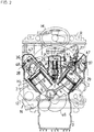
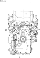
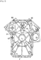
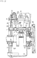
- Figs. 1 and 2 describe the front of the V type diesel engine of the present invention from which radiator R is removed.
- the main body of the V type diesel engine consists of crankcase 2, gearcase 3 and cylinder heads 28 and 29, which are all jointed with each other. Cylinders HL and HR are integrally formed in crankcase 2.
- Cylinder heads 28 and 29 are fixed respectively onto the tops of cylinders HL and HR. Cylinder head covers 36 and 37 are fixed respectively onto the tops of cylinder heads 28 and 29. Fuel injection nozzles 26 and 27 are disposed respectively in cylinder heads 29 and 29.
- Crankcase 2 which is made by die casting, is wide-open on the front side thereof for rapping a die.
- the opening portion of crankshaft 2 is widened by rotation of an engine.
- Four female screws 59 are tapped on the front side of crankcase 2, and a blocking member 56 is fastened onto the front side together with bolts screwed into female screws 59, so as to block widening of the front opening portion.
- Fuel injection nozzles 26 and 27 are disposed between cylinders arranged in a V shape, and are fed with high-pressure fuel discharged from fuel injection pump P, which is attached to a bracket 50 constituting a rear portion of governor case A, through high-pressure fuel pipes 10 and 11.
- each of pushrods 24 is interposed between camshaft 1 disposed in crankcase 2 and each of suction and exhaust valve arms 47 disposed respectively in each of cylinder head covers 36 and 37.
- Pushrods 24 are disposed between cylinders HL and HR arranged in a V shape. Moreover, governor case A is fixed on the top of crankcase 2 and gearcase 3 between pushrods 24. Governor device G is constructed in a governor chamber m which is an interior of governor case A.
- Pistons 6 and 7 are slidably inserted respectively in cylinders HL and HR. Pistons 6 and 7 are connected with crankshaft S respectively through connecting rods 4 and 5.
- Camshaft 1 is disposed between cylinders HL and HR, and is provided with suction and exhaust cams 31 and fuel injection pump driving cans 30.
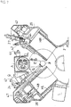
- a fuel feed pump driving cam 58 for driving fuel feed pump Q is disposed on camshaft 1 within the interior of crankcase 2. As shown in Fig. 7, a rod projects from fuel feed pump Q disposed between cylinders HL and HR, and abuts against fuel feed pump driving cam 58 so as to drive fuel feed pump Q and feed fuel injection pump P with fuel.
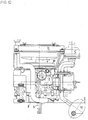
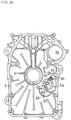
- pulleys 14 and 15 are fixed onto the front end of crankshaft S projecting from gearcase 3. Pulley 15 and a pulley 13 of operating oil pump 12 are bound with a belt 18. Also, pulley 14 and a pulley 16, which is fixed onto a fan shaft 40 of a radiator fan F disposed above pulley 14, are bound with a belt 17, so as to drive radiator fan F of radiator R.
- Fan shaft 40 of radiator fan F is supported by a bearing base 60 fixed onto the front surface of gearcase 3.
- the position of bearing base 60 is changeable in accordance with change of the position of fan shaft 40, so that positions of radiator fan F and radiator R can be changed.
- the engine body consisting of crankcase 2 and gearcase 3 forms left and right recesses under both cylinders HL and HR.
- Starter K is disposed in the right recess
- operating oil pump 12 is disposed in the left recess.
- a cooling water pump 8 is fixed onto the upper portion on left side of the front surface of gearcase 3, and feeds cooling water to the water jacket around left cylinder HL through a cooling water hole 39 and to the water jacket around right cylinder HR through a cooling water hole 38.
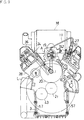
- Exhaust pipes 34 and 35 are interposed between the front surfaces of cylinder heads 28 and 29 and a muffler M shown in Fig. 2.
- muffler M is disposed above the engine and radiator R is disposed in front of the engine.
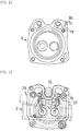
- a regulator lever 41 projects upwardly from governor G in governor chamber m disposed between cylinder heads 28 and 29 arranged in a V shape.
- Each end of fuel injection nozzles 26 and 27 screwed respectively into cylinder heads 26 and 27 is inserted into a precombustor 44, and on each side thereof, a glow plug 42 is fixedly inserted into precombustor 44.
- Fig. 2 shows a balance weight 46 formed around crankshaft S and fuel injection pump P disposed behind governor case A.
- a driving gear 21 is fixed onto the front end of crankshaft S within crankcase 2.
- Driving gear 21 engages with a driving gear 43 of lubricating oil pump D, which is supported within gearcase 3, on left side thereof in a front view, and engages with a camshaft driving gear 20 fixed onto camshaft 1 thereabove.
- Camshaft 20 engages with a governor shaft gear 19 fixed onto a governor shaft 9 of governor device G thereabove.
- a governor weight 25 is provided on the portion of governor shaft 9 disposed in governor case A.
- governor weight 25 opens and closes according to rotation of governor shaft 9, so that a L-like shaped governor lever 45 is rotated and a control rack of fuel injection pump P is slided. Also, operator can operate regulator lever 41 projecting from governor case A so as to change the rotational speed of engine.
- governor case A housing governor device G is disposed on the upper surface of a jointing portion of crankcase 2 and gearcase 3, and integrally forms bracket 50 at the extending portion thereof. Fuel injection pump P is fixed onto bracket 50.
- a bracket 49 projects upwardly from crankcase 2 so as to support an air cleaner C.
- Flywheel W is fixed onto crankshaft S.
- Crankcase 2 forms a dynamo housing space 85, therewithin dynamo X is fixed onto flywheel W and can rotate.
- a lubricating oil filter L is disposed on a left side of cylinder HL, which is the same with flywheel W, and behind operating oil pump 12.
- a fuel filter 22 is supported by a bracket, which projects from crankcase 2 or governor case A, and is hung down on a side of fuel injection pump P.
- Fuel returning pipes 100 are laid from fuel injection nozzles 26 and 27 and fuel injection pump P to fuel filter 22.
- governor case A is disposed on the top of crankcase 2 and gearcase 3 and extended so as to form bracket 50 for mounting fuel injection pump P.
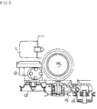
- Fig. 6 In Fig. 6 are shown cylinder HL and pulleys 13, 15 and 16, and is also the positional relations between operating oil pump 12 and lubricating oil filter L.
- lubricating oil filter L is disposed under cylinder HL and on the same side with operating oil pump 12.
- Fuel injection nozzles 26 and 27, governor device G and fuel injection pump P are disposed between pushrods 24.
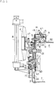
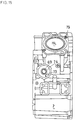
- Figs. 8 to 12 describe the V type diesel engine of vertical type, which disposes crankshaft S vertically.
- gearcase 3 constitutes a main oil pan.
- gearcase 3 is expanded downwardly so as to deepen its interior.
- crankshaft S projects downwardly from the bottom of gearcase 3.
- Radiator R which is disposed on the same side with gearcase 3 of the horizontal type engine, is disposed the upper portion of the vertical type engine, which is a portion opposite to gearcase 3. Flywheel W is fixed onto crankshaft S. Also, radiator fan F is fixed through a fan seat 51 onto crankshaft S.
- blocking member 56 is laid over the opening lower portion of crankcase 2 so as to prevent it from being widened by load.
- crankcase 2 and gearcase 3 are fastened together with bolts 63 screwed in pipe nocks 57.
- Pipe nocks 57 reinforce the round portions of bolts 63 fastening crankcase 2 and gearcase 3, so as to prevent the opening bottom of crankcase 2 from being widened by load.
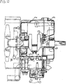
- the positional relations between crankcase 2 and gearcase 3 can be defined by parallel pins inserted into parallel pin holes B as shown in Fig. 13.
- crankcase 2 The construction of crankcase 2 will be detailed in accordance with Figs. 13 to 24.
- bearing journal 71 for journalling crankshaft S and bearing journal 75 for journalling camshaft 1 are bored through the interior of crankcase 2. Also, pivotal shaft portion 2a and oil passages 66, 86 and 93 are bored through crankcase 2.
- lubricating oil feeding system for feeding various portions with lubricating oil has comprised a main gallery from which crankshaft has received lubricating oil.
- the main gallerey has been made of a hole bored or cast through a boss formed within a side wall of a crankcase.
- supplement devises attached to the side wall of the crankcase has been necessarily disposed so as to avoid the boss portion including the main gallerey, thereby widening the entire lubrication system of the engine.
- a rotational direction of a crankshaft is often reversed in accordance with a kind of a machine driven by the engine. In this case, the rotational direction of a lubricating oil pump has had to be reversed.
- lubricating oil filter L is attached on a side of crankcase 2, and lubricating oil pump D is constructed in gearcase 3. Lubricating oil discharged from lubricating oil pump D and filtered through lubricating oil filter L can be fed to the journal portion journalling crankshaft S through oil passages in crankcase 2.
- pump rotors 90 and 61 of lubricating oil pump D can reverse their rotational directions.
- An axis of a lubricating oil pump shaft 55 takes the same position with a discharging hole 96, and a different position from grooves 97 and 98 and a suction hole 99.
- the vertical type engine has a filter net 53 mounted on gearcase 3 near suction hole 99 of lubricating oil pump D. Filter net 53 is engaged to projection 62 of gearcase 3.
- Pump shaft 55 is pivoted in gearcase 3.
- Driving gear 43 for driving lubricating oil pump D is fixed onto the end of lubricating oil pump shaft 55 and engages with a driving gear 21.
- Pump rotor 61 constituting a gear is fixed onto lubricating oil pump shaft 55.
- Pump rotor 90 engages with pump rotor 61 so as to slidably rotate around pump rotor 61.
- Lubricating oil filter L is disposed below fuel filter 22 and on a side of crankcase 2, so as to be behind operating oil pump 12 in a front view.
- Starter K is disposed on a right side of crankshaft 2 opposite to supplement devices N such as lubricating oil filter L and operating oil pump 12.
- Fuel filter 22 is disposed on the same side with flywheel W of crankcase 2. In a vertical type engine, it is disposed below radiator R but at the highest position of crankcase 2. In a horizontal type engine, it is disposed at the highest of fuel feeding system for fuel injection pump P, which is above fuel injection pump P, cylinder heads 28 and 29 and cylinder head covers 36 and 37. Accordingly, the fuel filtered through fuel filter 22 can be free of air.
- Fuel filter 22 is fed with fuel from fuel feed pump Q driven by fuel feed pump driving cam 58.
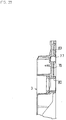
- Lubricating pump D comprises lubricating oil pump shaft 55, which is provided with pump rotors 90 and 61, disposed within a recess of gearcase 3, and is driven by driving gear 43. Suction hole 99 is opened toward the interior of gearcase 3 and connected to groove 98, and discharging hole 96 is bored between groove 97 and relief valve 65. Accordingly to rotation of pump rotors 90 and 61, lubricating oil in gearcase 3 is sucked into groove 98 through suction hole 99, and is discharged into the other groove 97. Then, the lubricating oil is pressured in groove 97 and is discharged into discharging hole 96. When the pressure of lubricating oil in discharging hole 96 reaches the predetermined degree, relief valve 95 operates to relieve the lubricating oil for safety.
- the lubricating oil discharged through discharging hole 96 and relief valve 65 is sent to an oil passage 66 of crankcase 2 through an oil passage 64 of gearcase 3.
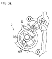
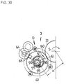
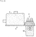
- gearcase 3 is classified into two types as shown in Figs. 29 and 30.
- pump rotors 90 and 61 are rotated clockwise in a rear view.
- Fig. 30 they are rotated counterclockwise in a rear view.
- crankshaft S and lubricating oil pump shaft 55 are similar in both cases, so that driving gear 21 and driving gear 43 can be made of common members.
- Pump rotor 90 of one type differs from that of the other type in its rotational axis while both types have the common distance a.
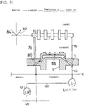
- Fig. 31 describes the circuit of lubricating oil.
- the lubricating oil discharged from lubricating oil pump D reaches lubricating oil filter L through oil passage 66 within crankcase 2.
- the lubricating oil which has lubricated the front end journal portion of camshaft 1, branches into branching oil passages 82 and 84, passes through oil holes bored within crankcase 2 and cylinder heads 28, and reaches rocker arm 47 so as to lubricate them.
- Fig. 13 describes an oil passage 66 of crankcase 2, which is connected with oil passage 64 of gearcase 3.
- oil passage 66 is bored through a boss of crankcase 2 and reaches a discharging hole 73 opening to an external lubricating oil filter seat 74 shown in Fig. 15.
- the lubricating oil discharged from discharging hole 73 penetrates lubricating oil filter L attached to external lubricating oil filter seat 74 from the exterior thereof, and is filtered through an inner filter within lubricating oil filter L.
- the filtered lubricating oil passed through oil passage 69 and reaches bearing journal 71 of crankcase 2, as shown in Figs. 23 and 24.
- An oil passage 72 branches out from oil passage 70 before bearing journal 71, and as shown in Fig. 17, an oil passage 76 is bored upwardly from oil passage 72 to bearing journal 75 of crankshaft 2 so as to lubricate the portion of camshaft 1 journalled by bearing journal 75.
- the lubricating oil which lubricated bearing journal 71, passes through inner oil passage 88 bored within crankshaft S and is discharged to bearing journal 80 of gearcase 3.
- Oil passage 79 is bored upwardly from bearing journal 80 to bearing journal 77 of gearcase 3, so that the lubricating oil, which passed through oil passage 79 lubricates the front end portion of camshaft 1 journalled by bearing journal 77.
- Branching oil passages 84 and 82 branch leftwards and rightwards from bearing journal 77 and are connected with respectively horizontal oil passages 83 and 81.
- horizontal oil passages 83 and 81 are connected respectively with oil passages 86 and 93 bored through cylinder HL portion of crankcase 2.
- oil passage 83 is connected with female screw 79 into which a head bolt is screwed so as to fix cylinder head 29 onto crankcase 2.
- Female screw 79 is connected with an oil passage 87 through a rocker arm shaft, so that each of rocker arms are lubricated.
- Gearcase 3 forms a pump mounting portion 3a for mounting cooling water pump 8 thereon at its upper left portion in a front view, and forms a pump portion 3b constituting lubricating oil pump D.
- fuel injection pump P is disposed between suction and exhaust cams 31 on the upper surface of crankcase 2.
- one pair of suction and exhaust cams 31 and the other pair thereof, which both disposed on camshaft 1, are apart from each other longitudinally with camshaft 1.
- Fuel injection pump driving cams 30 are disposed on camshaft 1 between both pairs of suction and exhaust cams 31.
- Regulator lever 41 supported on governor case A is disposed at the rear portion thereof.
- bracket 50 which is an extending portion of governor case A, is formed as a part of fuel pump P integrally, while bracket 50 is apart from fuel pump P in the other embodiment.
- Figs. 18 and 19 describe dynamo housing space 85 and a drain hole 91 which is also used for a hole guiding a lead of dynamo D.
- drain hole 91 is disposed at the lower portion of dynamo housing space 85.
- camshaft 1 which integrally forms suction and exhaust cams 31 and fuel injection pump driving cams 30, is disposed between cylinders HL and HR disposed in a V shape.
- Dynamo housing space 85 is disposed on a closed side of crankshaft below camshat 1.
- governor chamber m for housing governor device G and fuel injection pump chamber n for housing two fuel injection pumps P.
- the top of governor chamber m is covered with governor case A.
- Fuel injection pump chamber n is covered with bracket 50 projecting from governor case A, so that two fuel injection pumps P are fixed to bracket 50.
- Governor chamber m and fuel injection pump chamber n are formed by manner that molds are put out of crankcase 2 in a direction to gearcase 3 and in an upperward direction to a V bank, when crankcase 2 is die-casted.
- dynamo housing space 85 is constituded by the space below fuel injection pump driving cams 30 on the same side with flywheel W of crankcase 2. Dynamo housing space 85 is inserted into the interior of crankcase 2 so as to prevent dynamo D therein from projecting out of crankcase 2.
- a lead of dynamo D is required to be drawn outwardly from dynamo housing space 85.
- a lead guiding hole 91 is opened on a side of dynamo housing space 85.
- Lead guiding hole 91 is also used as a drain hole, so that a different drain hole from it is not required in dynamo housing space 85 of crankcase 2.
- the V type diesel engine of the present invention can be used both as a vertical type engine which disposes crankshaft S vertically and as a horizontal type engine which disposes crankshaft S horizontally.
- camshaft 1, governor device G and fuel injection pump P are specially disposed.
- Crankcase 2 and gearcase 3 are compacted.
- crankcase 2 Furthermore, in a recess formed on sides of crankcase 2 are disposed starter K, supplement device N, fuel feed pump Q, fuel filter 22, lubricating oil filter L and also, so that the entire V type diesel engine can be compacted.
Landscapes
- Engineering & Computer Science (AREA)
- Chemical & Material Sciences (AREA)
- Combustion & Propulsion (AREA)
- Mechanical Engineering (AREA)
- General Engineering & Computer Science (AREA)
- Cylinder Crankcases Of Internal Combustion Engines (AREA)
- Fuel-Injection Apparatus (AREA)
- Valve-Gear Or Valve Arrangements (AREA)
- Lubrication Of Internal Combustion Engines (AREA)
Applications Claiming Priority (13)
| Application Number | Priority Date | Filing Date | Title |
|---|---|---|---|
| JP02047195A JP3781448B2 (ja) | 1995-02-08 | 1995-02-08 | V型ディーゼルエンジンの潤滑機構 |
| JP2047095 | 1995-02-08 | ||
| JP02046995A JP3781447B2 (ja) | 1995-02-08 | 1995-02-08 | V型ディーゼルエンジン |
| JP20471/95 | 1995-02-08 | ||
| JP2047195 | 1995-02-08 | ||
| JP20469/95 | 1995-02-08 | ||
| JP20470/95 | 1995-02-08 | ||
| JP02047095A JP3751651B2 (ja) | 1995-02-08 | 1995-02-08 | V型ディーゼルエンジン |
| JP2046995 | 1995-02-08 | ||
| JP315477/95 | 1995-12-04 | ||
| JP7315477A JPH09151746A (ja) | 1995-12-04 | 1995-12-04 | V型ディーゼルエンジン |
| JP31547795 | 1995-12-04 | ||
| PCT/JP1996/000143 WO1996024758A1 (en) | 1995-02-08 | 1996-01-25 | V type diesel engine |
Publications (3)
| Publication Number | Publication Date |
|---|---|
| EP0809004A1 true EP0809004A1 (de) | 1997-11-26 |
| EP0809004A4 EP0809004A4 (de) | 1999-06-09 |
| EP0809004B1 EP0809004B1 (de) | 2003-09-17 |
Family
ID=27457387
Family Applications (1)
| Application Number | Title | Priority Date | Filing Date |
|---|---|---|---|
| EP96901118A Expired - Lifetime EP0809004B1 (de) | 1995-02-08 | 1996-01-25 | Dieselbrennkraftmaschine in v-bauart |
Country Status (4)
| Country | Link |
|---|---|
| US (1) | US5992393A (de) |
| EP (1) | EP0809004B1 (de) |
| DE (1) | DE69630019T2 (de) |
| WO (1) | WO1996024758A1 (de) |
Families Citing this family (28)
| Publication number | Priority date | Publication date | Assignee | Title |
|---|---|---|---|---|
| US6213096B1 (en) * | 1998-03-25 | 2001-04-10 | Sanshin Kogyo Kabushiki Kaisha | Fuel supply for direct injected engine |
| US6257187B1 (en) * | 1999-05-06 | 2001-07-10 | Caterpillar Inc. | Pivot shaft for an internal combustion engine |
| US6904883B2 (en) * | 2002-04-15 | 2005-06-14 | Tecumseh Products Company | Modular internal combustion engines |
| US6941914B2 (en) * | 2002-04-15 | 2005-09-13 | Tecumseh Products Company | Internal combustion engine |
| US6669453B1 (en) | 2002-05-10 | 2003-12-30 | Robert H. Breeden | Pump assembly useful in internal combustion engines |
| WO2004065768A2 (en) * | 2003-01-22 | 2004-08-05 | Karem Abraham E | Fail-operational internal combustion engine |
| JP3962341B2 (ja) * | 2003-02-14 | 2007-08-22 | 株式会社クボタ | エンジン |
| EP1627158B1 (de) * | 2003-05-28 | 2014-05-07 | The Boeing Company | Leistungsverzweigungs-getriebeantriebssystem und verfahren zum antrieb eines abtriebsritzels |
| JP4074860B2 (ja) * | 2004-03-19 | 2008-04-16 | 株式会社クボタ | 縦型多気筒ディーゼルエンジン |
| JP2006002741A (ja) * | 2004-06-21 | 2006-01-05 | Suzuki Motor Corp | 船外機用の2気筒v型ohvエンジン |
| US20080230036A1 (en) * | 2007-03-23 | 2008-09-25 | Bauman William D | Roller actuator for a mechanical fuel pump |
| DE102007025148A1 (de) * | 2007-05-30 | 2008-12-04 | Bayerische Motoren Werke Aktiengesellschaft | Brennkraftmaschine mit Zylinderkopf und Nebenaggregat sowie Verfahren zur Herstellung einer derartigen Brenn-kraft-maschine |
| US7650876B2 (en) * | 2008-04-10 | 2010-01-26 | Gm Global Technology Operations, Inc. | Fuel pump shaft and pump mounting in engine block |
| US7762239B2 (en) * | 2008-05-07 | 2010-07-27 | Ford Global Technologies, Llc | V-type engine with valley-mounted fuel pump |
| US20090293822A1 (en) * | 2008-05-28 | 2009-12-03 | Honda Motor Co., Ltd. | General-purpose v-type engine |
| US7568461B1 (en) * | 2008-06-20 | 2009-08-04 | Gm Global Technology Operations, Inc. | Tappet roller end shape for improved lubrication and combination with fuel pump and engine |
| US7823567B2 (en) * | 2009-01-06 | 2010-11-02 | Ford Global Technologies | Fuel pump for internal combustion engine |
| CN201372851Y (zh) * | 2009-01-06 | 2009-12-30 | 常柴股份有限公司 | V型水冷柴油机 |
| JP5281994B2 (ja) * | 2009-09-15 | 2013-09-04 | 株式会社クボタ | 多気筒ディーゼルエンジン |
| US20120260891A1 (en) * | 2011-04-18 | 2012-10-18 | Caterpillar Inc. | High Pressure Fuel Pump For An Internal Combustion Engine And Lubrication Strategy Therefor |
| CN102230427B (zh) * | 2011-06-20 | 2013-06-05 | 昆明瑞尔机电科技有限公司 | 立式单缸柴油机 |
| JP5711064B2 (ja) * | 2011-07-26 | 2015-04-30 | 本田技研工業株式会社 | バランサ付き内燃機関 |
| CN108266268B (zh) * | 2016-12-30 | 2020-06-09 | 中国石油天然气集团公司 | 发动机 |
| US11698050B2 (en) * | 2020-07-13 | 2023-07-11 | Powerhouse Engine Solutions Switzerland IP Holding GmbH | System and method for oil supply to pump |
| US11293331B1 (en) * | 2020-10-05 | 2022-04-05 | Kawasaki Jukogyo Kabushiki Kaisha | Cover structure for air-cooled engine |
| WO2022190253A1 (ja) | 2021-03-10 | 2022-09-15 | 本田技研工業株式会社 | V型エンジン及び作業機 |
| CN113738638B (zh) * | 2021-09-16 | 2023-12-22 | 中国北方发动机研究所(天津) | 一种新型单体泵泵箱结构 |
| CN118997917A (zh) * | 2024-10-21 | 2024-11-22 | 陕西北方动力有限责任公司 | 一种具有高集成进排气系统的高功率密度柴油机 |
Family Cites Families (19)
| Publication number | Priority date | Publication date | Assignee | Title |
|---|---|---|---|---|
| US1955799A (en) * | 1931-08-24 | 1934-04-24 | Gen Motors Corp | Pressure control system for blower-fed two-cycle engines |
| US2099852A (en) * | 1936-01-23 | 1937-11-23 | Viking Diesel Motor Corp | Internal combustion engine |
| US2429105A (en) * | 1942-07-14 | 1947-10-14 | Paxman Edward Philip | Construction of internalcombustion engines |
| DE966708C (de) | 1951-11-13 | 1957-09-05 | Hans List Dr Techn | Einspritzbrennkraftmaschine |
| US2821969A (en) * | 1952-12-29 | 1958-02-04 | Hovalwerk Ag Ospelt | V-type internal-combustion engine housing |
| US2796057A (en) * | 1954-12-15 | 1957-06-18 | Gen Motors Corp | Fuel supply system |
| JPS5162206A (en) * | 1974-11-27 | 1976-05-29 | Isuzu Motors Ltd | V gataenjin |
| DE2615742C2 (de) * | 1976-04-10 | 1984-10-18 | Mtu Motoren- Und Turbinen-Union Friedrichshafen Gmbh, 7990 Friedrichshafen | Dieselmotor |
| US4054108A (en) * | 1976-08-02 | 1977-10-18 | General Motors Corporation | Internal combustion engine |
| JPS5359132A (en) * | 1976-11-09 | 1978-05-27 | Kubota Ltd | Over-head valve v-shaped diesel engine |
| AT379865B (de) * | 1980-02-08 | 1986-03-10 | Simmering Graz Pauker Ag | Wassergekuehlte brennkraftmaschine |
| JPS586048A (ja) * | 1981-07-03 | 1983-01-13 | 日本電気株式会社 | 現用、予備電源切換制御回路 |
| JP2688435B2 (ja) * | 1989-01-17 | 1997-12-10 | マツダ株式会社 | V型エンジンの補機配置構造 |
| DE3935883C2 (de) * | 1989-10-27 | 1996-08-01 | Kloeckner Humboldt Deutz Ag | Viertakt-Dieselbrennkraftmaschine |
| DE4032590A1 (de) * | 1990-10-13 | 1992-04-16 | Porsche Ag | Hubkolbenmotor mit zwei v-foermig angeordneten zylinderreihen |
| JP3077430B2 (ja) * | 1992-12-28 | 2000-08-14 | スズキ株式会社 | V型エンジンのマウントブラケット |
| JP2628268B2 (ja) | 1993-04-12 | 1997-07-09 | 川崎重工業株式会社 | V型ディーゼルエンジン |
| DE4326159C5 (de) * | 1993-08-04 | 2006-01-19 | Daimlerchrysler Ag | Wassergekühlte mehrzylindrige Brennkraftmaschine mit V-förmig angeordneten Zylinderreihen |
| DE4340885B4 (de) * | 1993-12-01 | 2005-08-11 | Deutz Ag | V-förmig ausgebildete Brennkraftmaschine |
-
1996
- 1996-01-25 WO PCT/JP1996/000143 patent/WO1996024758A1/ja not_active Ceased
- 1996-01-25 US US08/875,932 patent/US5992393A/en not_active Expired - Fee Related
- 1996-01-25 DE DE69630019T patent/DE69630019T2/de not_active Expired - Lifetime
- 1996-01-25 EP EP96901118A patent/EP0809004B1/de not_active Expired - Lifetime
Also Published As
| Publication number | Publication date |
|---|---|
| US5992393A (en) | 1999-11-30 |
| DE69630019T2 (de) | 2004-06-09 |
| EP0809004B1 (de) | 2003-09-17 |
| EP0809004A4 (de) | 1999-06-09 |
| WO1996024758A1 (en) | 1996-08-15 |
| DE69630019D1 (de) | 2003-10-23 |
Similar Documents
| Publication | Publication Date | Title |
|---|---|---|
| EP0809004A1 (de) | Dieselbrennkraftmaschine in v-bauart | |
| US5495833A (en) | Lubricating oil feeding apparatus and oil feeding structure for starter driven gear bearing in internal combustion engine | |
| US4446828A (en) | Reciprocating internal combustion engine | |
| US6257178B1 (en) | Internal combustion engine for a motorcycle | |
| US4828519A (en) | Outboard motors | |
| US5572968A (en) | Internal-combustion engine having an oil return system | |
| EP0418046B2 (de) | Dieselmotor mit mechanischem Regler | |
| JP2802440B2 (ja) | 車両用エンジンユニット | |
| US7121163B2 (en) | Lubricating system for power unit for vehicle with internal combustion engine | |
| US6868819B2 (en) | Lubricating system for an outboard motor | |
| JPH1162545A (ja) | 船外機用dohc型エンジンのブローバイガス還元装置 | |
| KR100534153B1 (ko) | V형디젤엔진 | |
| JP3781448B2 (ja) | V型ディーゼルエンジンの潤滑機構 | |
| JP3751651B2 (ja) | V型ディーゼルエンジン | |
| JP3805506B2 (ja) | ドライサンプ潤滑式4サイクルエンジンユニット | |
| EP1552118B1 (de) | Ölkreislauf für doppelnockenwellenverbrennungsmotor | |
| JP3657303B2 (ja) | エンジンの潤滑装置 | |
| JP2970079B2 (ja) | 船外機のエンジン潤滑構造 | |
| JPH11117806A (ja) | バランサシャフト付きエンジン | |
| JPH08100618A (ja) | バーチカルエンジン | |
| JP4161774B2 (ja) | 4サイクルエンジンにおけるカムシャフト支持構造 | |
| JPH08100616A (ja) | バーチカルエンジンおよび船外機 | |
| JP3904681B2 (ja) | ドライサンプ潤滑式4サイクルエンジンユニット | |
| JP2652400B2 (ja) | 竪型エンジンの潤滑装置 | |
| JPH07109911A (ja) | 並列多気筒エンジンの潤滑装置 |
Legal Events
| Date | Code | Title | Description |
|---|---|---|---|
| PUAI | Public reference made under article 153(3) epc to a published international application that has entered the european phase |
Free format text: ORIGINAL CODE: 0009012 |
|
| 17P | Request for examination filed |
Effective date: 19970808 |
|
| AK | Designated contracting states |
Kind code of ref document: A1 Designated state(s): DE FR GB IT |
|
| A4 | Supplementary search report drawn up and despatched |
Effective date: 19990427 |
|
| AK | Designated contracting states |
Kind code of ref document: A4 Designated state(s): DE FR GB IT |
|
| 17Q | First examination report despatched |
Effective date: 20020207 |
|
| GRAH | Despatch of communication of intention to grant a patent |
Free format text: ORIGINAL CODE: EPIDOS IGRA |
|
| GRAS | Grant fee paid |
Free format text: ORIGINAL CODE: EPIDOSNIGR3 |
|
| GRAA | (expected) grant |
Free format text: ORIGINAL CODE: 0009210 |
|
| AK | Designated contracting states |
Kind code of ref document: B1 Designated state(s): DE FR GB IT |
|
| REG | Reference to a national code |
Ref country code: GB Ref legal event code: FG4D |
|
| REF | Corresponds to: |
Ref document number: 69630019 Country of ref document: DE Date of ref document: 20031023 Kind code of ref document: P |
|
| RAP2 | Party data changed (patent owner data changed or rights of a patent transferred) |
Owner name: YANMAR CO., LTD. |
|
| ET | Fr: translation filed | ||
| PLBE | No opposition filed within time limit |
Free format text: ORIGINAL CODE: 0009261 |
|
| STAA | Information on the status of an ep patent application or granted ep patent |
Free format text: STATUS: NO OPPOSITION FILED WITHIN TIME LIMIT |
|
| 26N | No opposition filed |
Effective date: 20040618 |
|
| PGFP | Annual fee paid to national office [announced via postgrant information from national office to epo] |
Ref country code: IT Payment date: 20100123 Year of fee payment: 15 Ref country code: FR Payment date: 20100209 Year of fee payment: 15 |
|
| PGFP | Annual fee paid to national office [announced via postgrant information from national office to epo] |
Ref country code: GB Payment date: 20100121 Year of fee payment: 15 |
|
| PGFP | Annual fee paid to national office [announced via postgrant information from national office to epo] |
Ref country code: DE Payment date: 20100331 Year of fee payment: 15 |
|
| GBPC | Gb: european patent ceased through non-payment of renewal fee |
Effective date: 20110125 |
|
| REG | Reference to a national code |
Ref country code: FR Ref legal event code: ST Effective date: 20110930 |
|
| PG25 | Lapsed in a contracting state [announced via postgrant information from national office to epo] |
Ref country code: FR Free format text: LAPSE BECAUSE OF NON-PAYMENT OF DUE FEES Effective date: 20110131 |
|
| PG25 | Lapsed in a contracting state [announced via postgrant information from national office to epo] |
Ref country code: GB Free format text: LAPSE BECAUSE OF NON-PAYMENT OF DUE FEES Effective date: 20110125 |
|
| REG | Reference to a national code |
Ref country code: DE Ref legal event code: R119 Ref document number: 69630019 Country of ref document: DE Effective date: 20110802 |
|
| PG25 | Lapsed in a contracting state [announced via postgrant information from national office to epo] |
Ref country code: IT Free format text: LAPSE BECAUSE OF NON-PAYMENT OF DUE FEES Effective date: 20110125 |
|
| PG25 | Lapsed in a contracting state [announced via postgrant information from national office to epo] |
Ref country code: DE Free format text: LAPSE BECAUSE OF NON-PAYMENT OF DUE FEES Effective date: 20110802 |