EP0808966B1 - Caveau funéraire - Google Patents
Caveau funéraire Download PDFInfo
- Publication number
- EP0808966B1 EP0808966B1 EP97108164A EP97108164A EP0808966B1 EP 0808966 B1 EP0808966 B1 EP 0808966B1 EP 97108164 A EP97108164 A EP 97108164A EP 97108164 A EP97108164 A EP 97108164A EP 0808966 B1 EP0808966 B1 EP 0808966B1
- Authority
- EP
- European Patent Office
- Prior art keywords
- chamber
- tomb
- aperture
- chamber according
- constructed
- Prior art date
- Legal status (The legal status is an assumption and is not a legal conclusion. Google has not performed a legal analysis and makes no representation as to the accuracy of the status listed.)
- Expired - Lifetime
Links
Images

Classifications
-
- E—FIXED CONSTRUCTIONS
- E04—BUILDING
- E04H—BUILDINGS OR LIKE STRUCTURES FOR PARTICULAR PURPOSES; SWIMMING OR SPLASH BATHS OR POOLS; MASTS; FENCING; TENTS OR CANOPIES, IN GENERAL
- E04H13/00—Monuments; Tombs; Burial vaults; Columbaria
-
- E—FIXED CONSTRUCTIONS
- E04—BUILDING
- E04H—BUILDINGS OR LIKE STRUCTURES FOR PARTICULAR PURPOSES; SWIMMING OR SPLASH BATHS OR POOLS; MASTS; FENCING; TENTS OR CANOPIES, IN GENERAL
- E04H13/00—Monuments; Tombs; Burial vaults; Columbaria
- E04H13/005—Ventilation systems therefor
Definitions
- the invention relates to a reusable burial chamber according to the preamble of claim 1.
- Such a burial chamber is known from FR 2 566 037.
- the chamber housing is designed to be watertight and is another ventilation device provided, the chamber-side opening in the lower region of the interior of the Burial chamber opens.
- the chamber housing consists of several frame-like wall parts placed on top of each other, the lowest frame-like wall part loose on a base plate rests; with a specific, commercially available design corresponding to this The lower base plate is completely dispensed with.
- About the Ventilation device is associated with the particular in its lower
- a good gas-tight design of the chamber housing Exchange of the gas atmosphere inside the chamber housing ensured, i.e. the putrefaction gases can escape from the Chamber chamber leak and air can enter the chamber housing sufficiently flow in quickly to decay within a certain period of time of 12 years, for example.
- the good ventilation properties this well-known burial chamber with "open", i.e. not sealed or below open chamber housings are thereby explains that in the soil around the Seepage water penetrating around the burial chamber in the interior of the burial chamber creates a certain negative pressure that causes air to flow into the Interior favors.
- the burial chamber known from DE 41 18 408 A1 tries among other things to solve this problem. by getting a grip on trying to get the pressure chamber housing form essentially dense to avoid water from can penetrate into the inside of the chamber housing.
- This construction is however, it has considerable other disadvantages.
- the unwanted can Ingress of water into the interior is not prevented with certainty become.
- hairline cracks can occur in the concrete, the density of the joints or the sealant used between the individual, stacked Chamber rings or between chamber housing and cover is not always guaranteed, or the one located below the earth's surface Airlock can be in heavy rain or when in the planting trough provided drainage openings 51 are clogged, flooded. is however, water once penetrated into the burial chamber according to DE 41 18 408 A1, it collects in the floor pan 24 and hinders the desired one there Decay process.
- the invention has for its object the disadvantages described above to avoid the known types as far as possible and especially one To create burial chamber that is comparatively inexpensive and of simple and compact design and at optimal conditions for a rapid decomposition process prevail.
- the burial chamber should comply with legal requirements, in particular meet the funeral laws or ordinances of the federal states.
- the watertight design of the chamber housing in particular by whose one-piece design can be achieved, enables the inventive Grave chamber without problems, for example, also in the backwater or groundwater area install.
- the watertight design of the chamber housing is a very good gas exchange due to the additional ventilation device within the burial chamber with sufficient oxygen supply and ensures good circulation of the gas atmosphere within the chamber, so that optimal conditions for rapid decay are present.
- the increase in the side wall forming the grave stone foundation with the chamber housing is preferably formed in one piece, it could also as separate base, being ensured by suitable centering means could be that the mutually assigned shaft sections in the respective Align components with each other.
- opening openings of the first ventilation device and the further ventilation device are arranged at different heights, which additionally a pressure difference promoting gas exchange can be exploited.
- the respective ventilation devices can basically be designed as disclosed in the two publications discussed above. Especially however, it is simple and inexpensive; if the at least one ventilation shaft the further ventilation device at least partially with a filter material such as B. filter sand is filled, causing odor nuisance with the required Security can be avoided.
- the first ventilation device can in this case in particular in accordance with DE 35 37 367 C2, that is to say with an activated carbon filter, be trained.
- a backflow flap is preferably in or at the drain opening provided that the burial chamber without additional drainage measures can also be installed in the backwater area.
- the drain opening opens a few centimeters above the chamber floor, so that on the floor of the chamber housing a few centimeters high water and dirt accumulation zone is formed in which water and impurities are retained and can be derived from a certain water level in a targeted and controllable manner. Adequate air humidity is also ensured.
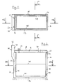
- the burial chamber comprises a trough-shaped chamber housing 10 and which is open at the top a cover 12 closing the upper opening of the chamber housing 10.
- the chamber housing 10 like the cover 12, is made in one piece from concrete produced, where other materials may also be conceivable.
- the Chamber housing 10 has a bottom 14 and four side walls 16, 18, 20 and 22, with open at the upper edges of the side walls Recesses 24 are formed, in the correspondingly shaped, along the engage lower projections 26 formed on the lower outer edges of the cover, so that the lid is positively held in its closed position and Rainwater cannot penetrate into the interior of the burial chamber.
- a vegetation mat 28 is placed on the top of the cover 12.
- An air and watertight closable through opening 30 serves as an opening for Urn burials.
- a ventilation device designated overall with 34 is formed in another through opening formed in the lid 32 .
- This Ventilation device 34 essentially comprises one in the passage opening 32 sealing pipe socket, an activated carbon filter and a Cover.
- the ventilation device 34 which is primarily used for venting the Interior of the burial chamber works, ends in the finished state of the Grave within the humus layer above the burial chamber.
- Another ventilation device serves primarily as a ventilation device for supplying fresh air to the interior of the burial chamber. It comprises two Ventilation shafts 35, which are inside the side wall 20 essentially are formed vertically and at their lower ends in the lower Area of the burial chamber via openings 36 in the interior of the burial chamber mouth, approximately at a height of 20 to 40 centimeters above the floor 14.
- the side wall 20 is extended upwards compared to the other side walls and at the same time reinforced and trained over the other side walls the upwardly projecting, base-like side wall section 38 serves as a foundation for a tombstone.
- the two ventilation shafts 35 extend to up into the base section 38 and end via openings 40 in the Lid 12 facing side wall of the base portion 38, above the ventilation device 34, but within the ground, the level of which is approximately defined by the horizontal upper end surface 42 of the base portion 38 is.
- the openings 40 are, as indicated in FIG. 3, closed with a grid.
- the ventilation shafts 35 are partially filled with a filter material, in particular filter sand, the height of the Filling depends on the filter properties of the material. In any case, must be ensured be that possible odor nuisance cannot occur.
- a through opening 44 is provided on the top of the base 14 and is media-tight can be connected to an external pipe system, not shown and through which water accumulating on the ground can be drained if necessary can.
- the through opening 44 can continue in the, not shown, the To be able to be closed by a non-return valve in a manner familiar to a person skilled in the art. Because of the slightly higher arrangement of the through opening than the floor 14 44 is a water and in the lower area of the chamber housing Dirt accumulation zone created, which is indicated by the dotted line 46.
- the side walls 18 running in the longitudinal direction of the chamber housing and 22, as is particularly clear from FIG. 3, are designed step-like, whereby projections 48 arise, which act as supports for an intermediate floor serve, which is used with double occupancy of the grave.
- the illustrated embodiment is a single grave with a possible double occupancy formed one above the other. However, it is understood that the Invention is not limited to this.
Landscapes
- Engineering & Computer Science (AREA)
- Architecture (AREA)
- Civil Engineering (AREA)
- Structural Engineering (AREA)
- Building Environments (AREA)
- Ventilation (AREA)
- Catching Or Destruction (AREA)
- Specific Sealing Or Ventilating Devices For Doors And Windows (AREA)
- Characterised By The Charging Evacuation (AREA)
- Pens And Brushes (AREA)
- Physical Deposition Of Substances That Are Components Of Semiconductor Devices (AREA)
- Valve Device For Special Equipments (AREA)
Claims (13)
- Caveau funéraire réutilisable, avec un boítier de caveau (10) globalement en forme d'auge, un couvercle (12) susceptible d'être posé sur le boítier de caveau, le cas échéant réalisé en plusieurs parties, et un premier dispositif d'aération (34) permettant un échange de gaz entre le volume intérieur du caveau funéraire et l'ambiance, l'ouverture, située côté caveau, du dispositif d'aération se trouvant à peu près à hauteur de la face inférieure du couvercle, le boítier de caveau (10) en forme d'auge étant étanche à l'eau, et un autre dispositif d'aération (35, 36, 40) étant prévu, permettant un échange de gaz entre le volume intérieur du caveau funéraire et l'ambiance, et dont au moins une ouverture (36), située côté caveau, débouche dans la zone inférieure du volume intérieur du caveau funéraire,
caractérisé en ce que l'autre dispositif d'aération comprend au moins un puits d'aération (35) établi dans une paroi latérale (20)appartenant au boítier de caveau (10), située à une hauteur plus élevée que les autres parois latérales (16, 18, 22) du boítier de caveau (10) et réalisée sous la forme de fondation de pierre funéraire, et une ouverture (40), reliée à l'ambiance, du au moins un puits d'aération (35) débouche dans la zone de la surélévation (38) de la paroi latérale (20) réalisée sous la forme de fondation de pierre funéraire, et ce que le premier dispositif d'aération (34) est réalisé sur le couvercle. - Caveau funéraire selon la revendication 1, caractérisé en ce que le boítier de caveau (10) en forme d'auge est réalisé d'une seule pièce.
- Caveau funéraire selon la revendication 1 ou 2, caractérisé en ce que l'ouverture (40) débouche sur le côté de la surélévation qui est tourné vers le couvercle (12).
- Caveau funéraire selon l'une des revendications précédentes, caractérisé en ce que les ouvertures, situées côté ambiance, du premier dispositif d'aération (34) et de l'autre dispositif d'aération (35, 36, 40) débouchent à des hauteurs différentes.
- Caveau funéraire selon la revendication 4, caractérisé en ce que l'ouverture (40), située côté ambiance, de l'autre dispositif d'aération se trouve au-dessus de l'ouverture, située côté ambiance, du premier dispositif d'aération (34).
- Caveau funéraire selon l'une des revendications précédentes, caractérisé en ce que le au moins un puits d'aération (35) de l'autre dispositif d'aération est rempli au moins partiellement d'un matériau filtrant, par exemple d'un sable filtrant.
- Caveau funéraire selon l'une des revendications précédentes, caractérisé en ce que, dans le boítier de caveau (10), dans sa zone inférieure, est réalisée une ouverture d'évacuation (44) continue, pour le raccordement fluidique d'un système d'assèchement par vidage.
- Caveau funéraire selon la revendication 7, caractérisé en ce qu'un clapet de retenue est prévu sur ou dans l'ouverture d'évacuation (44).
- Caveau funéraire selon la revendication 7 ou 8, caractérisé en ce que l'ouverture d'évacuation (44) est réalisée dans une paroi latérale (16).
- Caveau funéraire selon l'une des revendications 7 à 9, caractérisé en ce que l'ouverture d'évacuation (44) débouche, côté caveau, au-dessus du fond de caveau (14), de préférence à quelques centimètres au-dessus du fond de caveau.
- Caveau funéraire selon l'une des revendications précédentes, caractérisé en ce que, en face intérieure de deux parois latérales (18, 22) opposées du boítier de caveau (10), sont prévus des reposoirs réalisés sous la forme de saillies (48).
- Caveau funéraire selon la revendication 11, caractérisé en ce que la section transversale du volume intérieur du boítier de caveau (10) va en rétrécissant de façon étagée, en allant en direction du bas.
- Caveau funéraire selon l'une des revendications précédentes, caractérisé en ce qu'une ouverture (30) refermable est réalisée dans le couvercle (12) aux fins la disposition d'urne.
Applications Claiming Priority (2)
| Application Number | Priority Date | Filing Date | Title |
|---|---|---|---|
| DE29609187U DE29609187U1 (de) | 1996-05-22 | 1996-05-22 | Grabkammer |
| DE29609187U | 1996-05-22 |
Publications (3)
| Publication Number | Publication Date |
|---|---|
| EP0808966A2 EP0808966A2 (fr) | 1997-11-26 |
| EP0808966A3 EP0808966A3 (fr) | 1998-06-03 |
| EP0808966B1 true EP0808966B1 (fr) | 2003-03-26 |
Family
ID=8024283
Family Applications (1)
| Application Number | Title | Priority Date | Filing Date |
|---|---|---|---|
| EP97108164A Expired - Lifetime EP0808966B1 (fr) | 1996-05-22 | 1997-05-20 | Caveau funéraire |
Country Status (3)
| Country | Link |
|---|---|
| EP (1) | EP0808966B1 (fr) |
| AT (1) | ATE235631T1 (fr) |
| DE (2) | DE29609187U1 (fr) |
Families Citing this family (3)
| Publication number | Priority date | Publication date | Assignee | Title |
|---|---|---|---|---|
| DK0887492T3 (da) * | 1997-06-27 | 2000-07-10 | Schulze Peter Asmus | Element-skakt-grav |
| DE19926579A1 (de) * | 1999-06-11 | 2001-01-04 | Messer Griesheim Gmbh | Verfahren und Vorrichtung zur Verwesung von Leichen |
| DE19953740B4 (de) * | 1999-11-09 | 2007-12-06 | Ackermann, Günter | Grabkammer |
Family Cites Families (9)
| Publication number | Priority date | Publication date | Assignee | Title |
|---|---|---|---|---|
| US1641124A (en) * | 1926-10-04 | 1927-08-30 | Thomas F Cullinan | Ventilating system for mausoleums |
| US2783523A (en) * | 1955-10-10 | 1957-03-05 | Halley James Leo | Burial vault |
| DE2723769A1 (de) * | 1977-05-26 | 1978-12-07 | Johann Pfingstgraef | Mehrfachgrabstaette |
| FR2461795A1 (fr) * | 1979-07-18 | 1981-02-06 | Augias Francis | Cellule mortuaire monoplace a double ventilation exterieure et interieure par appareil purificateur de gaz avec admission d'air forcee et echappement sous faible pression |
| DE3150023A1 (de) * | 1980-09-20 | 1983-06-23 | Lambert 5401 Dieblich Schäfer | Wiederverwendbare grabkammer aus beton |
| FR2566037B1 (fr) * | 1984-06-19 | 1986-11-07 | Sabla Sa | Sepulture a ventilation interne |
| DE3537367A1 (de) * | 1985-10-21 | 1987-04-23 | Gerhard Suckfuell | Grabkammer |
| FR2688819B1 (fr) * | 1992-03-20 | 1998-11-27 | Augival Sa | Perfectionnements apportes aux dispositifs d'aeration des caveaux mortuaires. |
| DE29606819U1 (de) * | 1996-04-03 | 1996-07-11 | Martin Reinhard | Belüftungssystem für eine Grabkammer |
-
1996
- 1996-05-22 DE DE29609187U patent/DE29609187U1/de not_active Expired - Lifetime
-
1997
- 1997-05-20 AT AT97108164T patent/ATE235631T1/de not_active IP Right Cessation
- 1997-05-20 DE DE59709596T patent/DE59709596D1/de not_active Expired - Fee Related
- 1997-05-20 EP EP97108164A patent/EP0808966B1/fr not_active Expired - Lifetime
Also Published As
| Publication number | Publication date |
|---|---|
| ATE235631T1 (de) | 2003-04-15 |
| DE59709596D1 (de) | 2003-04-30 |
| EP0808966A3 (fr) | 1998-06-03 |
| DE29609187U1 (de) | 1996-08-14 |
| EP0808966A2 (fr) | 1997-11-26 |
Similar Documents
| Publication | Publication Date | Title |
|---|---|---|
| AT507028A1 (de) | Erdbeckenfermenter | |
| DE10143985C1 (de) | Rinnenabschnitt zur Herstellung einer Rinne zur Aufnahme von Oberflächenwasser | |
| DE60218331T2 (de) | Schadstoffeeindämmungssystem | |
| DE202017103566U1 (de) | Baumschutz mit Regenwasserbewirtschaftung | |
| EP0808966B1 (fr) | Caveau funéraire | |
| DE3534327C1 (en) | Prefabricated container forming coffin-receiving vault - comprises GRP trough and lid with perimeter holes allowing air circulation | |
| DE10326636A1 (de) | Schachtabdeckung mit Belüftung | |
| DE19536896C2 (de) | Versickerungsrinnensystem | |
| DE4118408A1 (de) | Grabkammer | |
| EP0657015B1 (fr) | Embase de cheminee | |
| DE19860160C2 (de) | Wasserablauf | |
| DE19953740B4 (de) | Grabkammer | |
| EP1469145B1 (fr) | Caveau réutilisable et dispositif pour enterrement | |
| EP0528124B1 (fr) | Caveau funéraire | |
| DE3150023A1 (de) | Wiederverwendbare grabkammer aus beton | |
| EP0619407A1 (fr) | Caveau funéraire | |
| AT403492B (de) | Schachtabschluss | |
| DE202008015908U1 (de) | Baumquartier | |
| EP0918120A2 (fr) | Caveau funéraire avec un élément inférieur formant une cavité | |
| EP0791702A1 (fr) | Cavité funéraire pour la décomposition biologique accélérée des substances organiques dans du sol saturé d'eau ou transportant l'eau provisoirement | |
| DE4311796A1 (de) | Einlagerungssystem | |
| DE4211601C2 (de) | Schluckbrunnen | |
| DE19602897A1 (de) | Handhabungsfreundliche, wasserdichte Schachtabdeckung | |
| DE4318662A1 (de) | Grabanlage | |
| EP0860550A2 (fr) | Dispositif de plantation d'arbres |
Legal Events
| Date | Code | Title | Description |
|---|---|---|---|
| PUAI | Public reference made under article 153(3) epc to a published international application that has entered the european phase |
Free format text: ORIGINAL CODE: 0009012 |
|
| AK | Designated contracting states |
Kind code of ref document: A2 Designated state(s): AT CH DE LI |
|
| PUAL | Search report despatched |
Free format text: ORIGINAL CODE: 0009013 |
|
| AK | Designated contracting states |
Kind code of ref document: A3 Designated state(s): AT CH DE LI |
|
| 17P | Request for examination filed |
Effective date: 19981030 |
|
| 17Q | First examination report despatched |
Effective date: 20010605 |
|
| GRAH | Despatch of communication of intention to grant a patent |
Free format text: ORIGINAL CODE: EPIDOS IGRA |
|
| GRAH | Despatch of communication of intention to grant a patent |
Free format text: ORIGINAL CODE: EPIDOS IGRA |
|
| GRAA | (expected) grant |
Free format text: ORIGINAL CODE: 0009210 |
|
| AK | Designated contracting states |
Designated state(s): AT CH DE LI |
|
| REG | Reference to a national code |
Ref country code: CH Ref legal event code: EP |
|
| REF | Corresponds to: |
Ref document number: 59709596 Country of ref document: DE Date of ref document: 20030430 Kind code of ref document: P |
|
| REG | Reference to a national code |
Ref country code: CH Ref legal event code: NV Representative=s name: SCHMAUDER & PARTNER AG PATENTANWALTSBUERO |
|
| PLBE | No opposition filed within time limit |
Free format text: ORIGINAL CODE: 0009261 |
|
| STAA | Information on the status of an ep patent application or granted ep patent |
Free format text: STATUS: NO OPPOSITION FILED WITHIN TIME LIMIT |
|
| 26N | No opposition filed |
Effective date: 20031230 |
|
| REG | Reference to a national code |
Ref country code: CH Ref legal event code: PCAR Free format text: SCHMAUDER & PARTNER AG PATENT- UND MARKENANWAELTE VSP;ZWAENGIWEG 7;8038 ZUERICH (CH) |
|
| PGFP | Annual fee paid to national office [announced via postgrant information from national office to epo] |
Ref country code: AT Payment date: 20090522 Year of fee payment: 13 |
|
| PGFP | Annual fee paid to national office [announced via postgrant information from national office to epo] |
Ref country code: CH Payment date: 20090525 Year of fee payment: 13 |
|
| PGFP | Annual fee paid to national office [announced via postgrant information from national office to epo] |
Ref country code: DE Payment date: 20090724 Year of fee payment: 13 |
|
| REG | Reference to a national code |
Ref country code: CH Ref legal event code: PL |
|
| PG25 | Lapsed in a contracting state [announced via postgrant information from national office to epo] |
Ref country code: AT Free format text: LAPSE BECAUSE OF NON-PAYMENT OF DUE FEES Effective date: 20100520 |
|
| PG25 | Lapsed in a contracting state [announced via postgrant information from national office to epo] |
Ref country code: LI Free format text: LAPSE BECAUSE OF NON-PAYMENT OF DUE FEES Effective date: 20100531 Ref country code: CH Free format text: LAPSE BECAUSE OF NON-PAYMENT OF DUE FEES Effective date: 20100531 |
|
| PG25 | Lapsed in a contracting state [announced via postgrant information from national office to epo] |
Ref country code: DE Free format text: LAPSE BECAUSE OF NON-PAYMENT OF DUE FEES Effective date: 20101201 |