EP0808966A2 - Caveau funéraire - Google Patents
Caveau funéraire Download PDFInfo
- Publication number
- EP0808966A2 EP0808966A2 EP97108164A EP97108164A EP0808966A2 EP 0808966 A2 EP0808966 A2 EP 0808966A2 EP 97108164 A EP97108164 A EP 97108164A EP 97108164 A EP97108164 A EP 97108164A EP 0808966 A2 EP0808966 A2 EP 0808966A2
- Authority
- EP
- European Patent Office
- Prior art keywords
- chamber
- ventilation device
- chamber according
- digging
- opening
- Prior art date
- Legal status (The legal status is an assumption and is not a legal conclusion. Google has not performed a legal analysis and makes no representation as to the accuracy of the status listed.)
- Granted
Links
- 238000009933 burial Methods 0.000 title claims abstract description 40
- 238000009423 ventilation Methods 0.000 claims abstract description 50
- 239000000463 material Substances 0.000 claims description 5
- 239000004576 sand Substances 0.000 claims description 3
- 239000004575 stone Substances 0.000 claims 2
- XLYOFNOQVPJJNP-UHFFFAOYSA-N water Substances O XLYOFNOQVPJJNP-UHFFFAOYSA-N 0.000 description 16
- 239000007789 gas Substances 0.000 description 9
- 238000000354 decomposition reaction Methods 0.000 description 5
- OKTJSMMVPCPJKN-UHFFFAOYSA-N Carbon Chemical compound [C] OKTJSMMVPCPJKN-UHFFFAOYSA-N 0.000 description 4
- 238000000034 method Methods 0.000 description 4
- 238000009825 accumulation Methods 0.000 description 3
- 239000003673 groundwater Substances 0.000 description 3
- 230000000149 penetrating effect Effects 0.000 description 3
- QVGXLLKOCUKJST-UHFFFAOYSA-N atomic oxygen Chemical compound [O] QVGXLLKOCUKJST-UHFFFAOYSA-N 0.000 description 2
- 235000019645 odor Nutrition 0.000 description 2
- 229910052760 oxygen Inorganic materials 0.000 description 2
- 239000001301 oxygen Substances 0.000 description 2
- 239000000853 adhesive Substances 0.000 description 1
- 230000001070 adhesive effect Effects 0.000 description 1
- 238000005352 clarification Methods 0.000 description 1
- 238000010276 construction Methods 0.000 description 1
- 238000011109 contamination Methods 0.000 description 1
- 230000008878 coupling Effects 0.000 description 1
- 238000010168 coupling process Methods 0.000 description 1
- 238000005859 coupling reaction Methods 0.000 description 1
- 239000003864 humus Substances 0.000 description 1
- 239000012535 impurity Substances 0.000 description 1
- 230000035515 penetration Effects 0.000 description 1
- 230000000717 retained effect Effects 0.000 description 1
- 239000000565 sealant Substances 0.000 description 1
- 239000002689 soil Substances 0.000 description 1
Images
Classifications
-
- E—FIXED CONSTRUCTIONS
- E04—BUILDING
- E04H—BUILDINGS OR LIKE STRUCTURES FOR PARTICULAR PURPOSES; SWIMMING OR SPLASH BATHS OR POOLS; MASTS; FENCING; TENTS OR CANOPIES, IN GENERAL
- E04H13/00—Monuments; Tombs; Burial vaults; Columbaria
-
- E—FIXED CONSTRUCTIONS
- E04—BUILDING
- E04H—BUILDINGS OR LIKE STRUCTURES FOR PARTICULAR PURPOSES; SWIMMING OR SPLASH BATHS OR POOLS; MASTS; FENCING; TENTS OR CANOPIES, IN GENERAL
- E04H13/00—Monuments; Tombs; Burial vaults; Columbaria
- E04H13/005—Ventilation systems therefor
Definitions
- the invention relates to a re-usable burial chamber with an overall trough-shaped chamber housing, a cover that can be placed on the chamber housing, possibly in several parts, and a first ventilation device formed on the cover, which enables gas exchange between the interior of the burial chamber and the surroundings, the chamber-side opening of the first ventilation device is located approximately at the bottom of the lid.
- Such a burial chamber is known from DE 35 37 367 C2.
- the chamber housing consists of several frame-like wall parts placed one on top of the other, the lowest frame-like wall lying loosely on a base plate; in the case of a specific, commercially available design in accordance with this document, the lower base plate is completely dispensed with.
- a good exchange of the gas atmosphere located in the chamber housing is ensured via the ventilation device in connection with the design of the chamber housing, which is not gas-tight especially in its lower region, i.e. the decomposition gases can escape from the chamber housing sufficiently quickly and air can flow into the chamber housing sufficiently quickly to ensure decay within a certain period of time, for example 12 years.
- the good ventilation properties of this known burial chamber with "open”, i.e. Chamber housings that are not sealed or open at the bottom This explains the fact that seeping water penetrating into the soil around the burial chamber creates a certain negative pressure in the interior of the burial chamber, which favors the inflow of air into the interior.
- this "open" design has the disadvantage that when this burial chamber is installed in the accumulation, adhesive, stratified or groundwater area, an extensive one Drainage is necessary to prevent water from entering the interior or to drain water that has penetrated as quickly as possible. Such drainage systems and the associated costs for the drainage and possible clarification of the drain water can be considerable.
- the burial chamber known from DE 41 18 408 A1 tries among other things to solve this problem. by getting under control by trying to make the pressure-shaped chamber housing essentially tight in order to avoid that water can penetrate into the interior of the chamber housing from the outside.
- This construction has considerable other disadvantages. Firstly, the unwanted penetration of water into the interior cannot be prevented with certainty. For example, hairline cracks can occur in the concrete, the density of the joints or the sealant used between the individual, stacked chamber rings or between the chamber housing and cover is not always guaranteed, or the airlock located below the surface of the earth can be exposed to heavy rain or when the Plant trough provided drainage openings 51 are blocked, flooded. However, once water has penetrated into the burial chamber according to DE 41 18 408 A1, it collects in the floor pan 24 and hinders the desired decomposition process there.
- the desired decomposition process is also decisively inhibited in this prior art by the inadequate ventilation of the interior taking place. Any excess pressure in the interior due to putrefaction gases can be removed via the ventilation device formed on the cover, but otherwise the supply of oxygen can only take place via changing atmospheric air pressure, the exchange not being sufficient to ensure the putrefaction process in the desired manner to accelerate, especially since the drain hose used in practice for gas distribution clogs up relatively quickly.
- the invention has for its object to avoid the disadvantages of the two known types described above as possible and in particular to create a burial chamber which is comparatively inexpensive and in which optimal conditions for a rapid decomposition process prevail.
- the burial chamber should meet the legal requirements, in particular the funeral laws and ordinances of the federal states.
- the trough-shaped chamber housing is designed to be gas-tight and watertight and that in addition to the ventilation device installed in the cover, a further ventilation device is provided which enables gas circulation between the interior of the burial chamber and the environment and at least one chamber-side opening opens into the lower part of the interior of the burial chamber.
- the watertight design of the chamber housing which can be achieved in particular by its one-piece design, enables the burial chamber according to the invention to be easily installed, for example, in the backwater or groundwater area.
- a very good gas exchange within the burial chamber with sufficient oxygen supply and good circulation of the gas atmosphere within the chamber is ensured due to the additional ventilation device, so that optimal conditions for rapid decomposition are present.
- the further ventilation device can basically comprise a shaft or a pipe, which is either led upwards in the interior of the burial chamber and, for. B. with the interposition of a suitable coupling piece, is passed through the cover, or which is passed through a side wall of the chamber housing to the outside and then outside the burial chamber upwards and ends outdoors or underground, as in the prior art described at the beginning is disclosed, suitable airlocks or filters can be provided.
- the ventilation shaft is preferably integrated in a side wall of the chamber housing.
- the side wall in which the ventilation shaft is integrated is preferably raised over the other side walls and is designed as a tombstone foundation, the ventilation shaft opening outward in the area of the elevation, but preferably still within the ground.
- the elevation of the side wall forming the tombstone foundation is preferably formed in one piece with the chamber housing, it could also be designed as a separate base, whereby suitable centering means could ensure that the mutually assigned shaft sections in the respective components are aligned with one another.
- the openings of the first ventilation device and the further ventilation device opening into the surroundings are arranged at different heights, as a result of which a pressure difference which promotes gas exchange can also be used.
- the respective ventilation devices can in principle be designed as disclosed in the two documents discussed above. However, it is particularly simple and inexpensive if the at least one ventilation shaft of the further ventilation device is at least partially covered with a filter material such as, for. B. filter sand is filled, whereby odors can be avoided with the necessary security.
- the first ventilation device can in particular be designed in accordance with DE 35 37 367 C2, that is to say with an activated carbon filter.
- a particularly advantageous development of the invention in the chamber housing is a continuous one in its lower region Drain opening designed for the fluid-tight connection of a drainage system.
- Water that collects the chamber housing can thus be drained off via a pipe system and, if necessary, cleaned in a biological filter shaft.
- a backflow flap is preferably provided in or at the drain opening, as a result of which the burial chamber can also be installed in the backwater area without additional drainage measures. Due to the targeted drainage of water entering the chamber housing via a pipe system, contamination of the groundwater with the required safety is excluded.
- the drain opening opens a few centimeters above the chamber bottom, so that a few centimeters high water and dirt accumulation zone is formed on the bottom of the chamber housing, in which water and impurities are retained and are specifically and controllably drained off from a certain water level will. Adequate air humidity is also ensured.
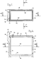
- the burial chamber comprises a trough-shaped chamber housing 10 which is open at the top and a cover 12 which closes the upper opening of the chamber housing 10.
- the chamber housing 10 is made in one piece from concrete, other materials also possibly being conceivable.
- the chamber housing 10 has a bottom 14 and four side walls 16, 18, 20 and 22, with recesses 24 open to the outside being formed on the upper edges of the side walls, into which correspondingly shaped projections 26 engage, which are formed along the lower outer edges of the cover 12 , so that the cover is positively held in its closed position and rainwater cannot penetrate into the interior of the burial chamber.
- a vegetation mat 28 is placed on the top of the cover 12.
- An airtight and watertight closable through opening 30 serves as an opening for urn burials.
- a ventilation device generally designated 34, is inserted, which is designed in the manner of DE 35 37 367 C2, reference being expressly made to this document with regard to details in this regard.
- This ventilation device 34 essentially comprises a pipe socket inserted sealingly into the through opening 32, an activated carbon filter and a cover.
- the ventilation device 34 which works primarily as a ventilation of the interior of the burial chamber, ends in the finished state of the grave within the humus layer located above the burial chamber.
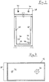
- Another ventilation device serves primarily as a ventilation device for supplying fresh air into the interior of the burial chamber. It comprises two ventilation shafts 35, which are designed to run essentially vertically in the interior of the side wall 20 and open at their lower ends in the lower region of the burial chamber via openings 36 into the interior of the burial chamber, approximately at a height of 20 to 40 centimeters above the ground 14.
- the side wall 20 is extended upwards relative to the other side walls and, at the same time, is formed and reinforced relative to the other side walls the upwardly projecting, base-like side wall section 38 serves as the foundation for a tombstone.
- the two ventilation shafts 35 extend upward into the base section 38 and end via openings 40 in the side wall of the base section 38 facing the cover 12, above the ventilation device 34, but within the ground, the level of which is approximately through the horizontal upper end surface 42 of the base section 38 is defined.
- the openings 40 are closed by means of a grid, as indicated in FIG. 3.
- the ventilation shafts 35 are partially filled with a filter material, in particular filter sand, the amount of the filling depending on the filter properties of the material. In any case, it must be ensured that possible odor nuisance cannot occur.
- a through opening 44 is provided a few centimeters above the top of the bottom 14, which can be connected in a media-tight manner to an external pipe system (not shown) and via which water accumulating on the bottom can be drained off if necessary.
- the passage opening 44 can furthermore be closed by means of a non-return flap in a manner not shown in detail which is familiar to the person skilled in the art. Due to the slightly higher arrangement of the through opening 44 than the bottom 14, a water and dirt accumulation zone is created in the lower region of the chamber housing, which is indicated by the dotted line 46.
- the side walls 18 and 22 extending in the longitudinal direction of the chamber housing are, as is particularly clear from FIG. 3, step-shaped, whereby projections 48 are formed which serve as supports for an intermediate floor which is used when the grave is occupied twice.
- the illustrated embodiment is designed as a single grave with a possible double occupancy one above the other. However, it is to be understood that the invention is not so limited.
Landscapes
- Engineering & Computer Science (AREA)
- Architecture (AREA)
- Civil Engineering (AREA)
- Structural Engineering (AREA)
- Building Environments (AREA)
- Pens And Brushes (AREA)
- Physical Deposition Of Substances That Are Components Of Semiconductor Devices (AREA)
- Valve Device For Special Equipments (AREA)
- Catching Or Destruction (AREA)
- Specific Sealing Or Ventilating Devices For Doors And Windows (AREA)
- Characterised By The Charging Evacuation (AREA)
- Ventilation (AREA)
Applications Claiming Priority (2)
| Application Number | Priority Date | Filing Date | Title |
|---|---|---|---|
| DE29609187U DE29609187U1 (de) | 1996-05-22 | 1996-05-22 | Grabkammer |
| DE29609187U | 1996-05-22 |
Publications (3)
| Publication Number | Publication Date |
|---|---|
| EP0808966A2 true EP0808966A2 (fr) | 1997-11-26 |
| EP0808966A3 EP0808966A3 (fr) | 1998-06-03 |
| EP0808966B1 EP0808966B1 (fr) | 2003-03-26 |
Family
ID=8024283
Family Applications (1)
| Application Number | Title | Priority Date | Filing Date |
|---|---|---|---|
| EP97108164A Expired - Lifetime EP0808966B1 (fr) | 1996-05-22 | 1997-05-20 | Caveau funéraire |
Country Status (3)
| Country | Link |
|---|---|
| EP (1) | EP0808966B1 (fr) |
| AT (1) | ATE235631T1 (fr) |
| DE (2) | DE29609187U1 (fr) |
Cited By (2)
| Publication number | Priority date | Publication date | Assignee | Title |
|---|---|---|---|---|
| WO2000076448A3 (fr) * | 1999-06-11 | 2001-04-05 | Messer Griesheim Gmbh | Procede et dispositif pour la decomposition des cadavres |
| EP1099809A3 (fr) * | 1999-11-09 | 2003-01-15 | Günter Ackermann | Caveau funéraire |
Families Citing this family (1)
| Publication number | Priority date | Publication date | Assignee | Title |
|---|---|---|---|---|
| DE59701040D1 (de) * | 1997-06-27 | 2000-02-24 | Schulze Peter Asmus | Element-Schacht-Grab |
Family Cites Families (9)
| Publication number | Priority date | Publication date | Assignee | Title |
|---|---|---|---|---|
| US1641124A (en) * | 1926-10-04 | 1927-08-30 | Thomas F Cullinan | Ventilating system for mausoleums |
| US2783523A (en) * | 1955-10-10 | 1957-03-05 | Halley James Leo | Burial vault |
| DE2723769A1 (de) * | 1977-05-26 | 1978-12-07 | Johann Pfingstgraef | Mehrfachgrabstaette |
| FR2461795A1 (fr) * | 1979-07-18 | 1981-02-06 | Augias Francis | Cellule mortuaire monoplace a double ventilation exterieure et interieure par appareil purificateur de gaz avec admission d'air forcee et echappement sous faible pression |
| DE3150023A1 (de) * | 1980-09-20 | 1983-06-23 | Lambert 5401 Dieblich Schäfer | Wiederverwendbare grabkammer aus beton |
| FR2566037B1 (fr) * | 1984-06-19 | 1986-11-07 | Sabla Sa | Sepulture a ventilation interne |
| DE3537367A1 (de) * | 1985-10-21 | 1987-04-23 | Gerhard Suckfuell | Grabkammer |
| FR2688819B1 (fr) * | 1992-03-20 | 1998-11-27 | Augival Sa | Perfectionnements apportes aux dispositifs d'aeration des caveaux mortuaires. |
| DE29606819U1 (de) * | 1996-04-03 | 1996-07-11 | Martin, Reinhard, 87736 Böhen | Belüftungssystem für eine Grabkammer |
-
1996
- 1996-05-22 DE DE29609187U patent/DE29609187U1/de not_active Expired - Lifetime
-
1997
- 1997-05-20 DE DE59709596T patent/DE59709596D1/de not_active Expired - Fee Related
- 1997-05-20 EP EP97108164A patent/EP0808966B1/fr not_active Expired - Lifetime
- 1997-05-20 AT AT97108164T patent/ATE235631T1/de not_active IP Right Cessation
Cited By (2)
| Publication number | Priority date | Publication date | Assignee | Title |
|---|---|---|---|---|
| WO2000076448A3 (fr) * | 1999-06-11 | 2001-04-05 | Messer Griesheim Gmbh | Procede et dispositif pour la decomposition des cadavres |
| EP1099809A3 (fr) * | 1999-11-09 | 2003-01-15 | Günter Ackermann | Caveau funéraire |
Also Published As
| Publication number | Publication date |
|---|---|
| EP0808966A3 (fr) | 1998-06-03 |
| DE29609187U1 (de) | 1996-08-14 |
| ATE235631T1 (de) | 2003-04-15 |
| DE59709596D1 (de) | 2003-04-30 |
| EP0808966B1 (fr) | 2003-03-26 |
Similar Documents
| Publication | Publication Date | Title |
|---|---|---|
| EP0808966B1 (fr) | Caveau funéraire | |
| DE19536896C2 (de) | Versickerungsrinnensystem | |
| DE3534327C1 (en) | Prefabricated container forming coffin-receiving vault - comprises GRP trough and lid with perimeter holes allowing air circulation | |
| DE69427077T2 (de) | Vorrichtung für die schnelle Mineralisierung von vergrabenen Leichen, bestehend aus ortsfesten Grabnischen und Särgen dazu entwickelt | |
| EP0657015B2 (fr) | Embase de cheminee | |
| DE4118408A1 (de) | Grabkammer | |
| DE19953740B4 (de) | Grabkammer | |
| EP1469145B1 (fr) | Caveau réutilisable et dispositif pour enterrement | |
| EP0619407A1 (fr) | Caveau funéraire | |
| DE3150023A1 (de) | Wiederverwendbare grabkammer aus beton | |
| DE29813992U1 (de) | Wiederverwendbare Grabkammer | |
| DE202010002248U1 (de) | Urnenerdkammer | |
| EP0791702A1 (fr) | Cavité funéraire pour la décomposition biologique accélérée des substances organiques dans du sol saturé d'eau ou transportant l'eau provisoirement | |
| EP0918120A2 (fr) | Caveau funéraire avec un élément inférieur formant une cavité | |
| EP0528124B1 (fr) | Caveau funéraire | |
| DE9311682U1 (de) | Grabkammer | |
| DE29520830U1 (de) | Begräbniskammer | |
| DE29920759U1 (de) | Grabkammer | |
| DE19853336A1 (de) | Grabkammer mit einem einen Hohlraum bildenden Unterteil | |
| DE1484461A1 (de) | Anlage zur Entwaesserung einer Bauwerkswand | |
| DE102004053414A1 (de) | Bestattungseinrichtung für Urnen | |
| DE19602897A1 (de) | Handhabungsfreundliche, wasserdichte Schachtabdeckung | |
| DE4318662A1 (de) | Grabanlage | |
| DE9109653U1 (de) | Grabkammer | |
| DE202006009057U1 (de) | Grabkammersystem |
Legal Events
| Date | Code | Title | Description |
|---|---|---|---|
| PUAI | Public reference made under article 153(3) epc to a published international application that has entered the european phase |
Free format text: ORIGINAL CODE: 0009012 |
|
| AK | Designated contracting states |
Kind code of ref document: A2 Designated state(s): AT CH DE LI |
|
| PUAL | Search report despatched |
Free format text: ORIGINAL CODE: 0009013 |
|
| AK | Designated contracting states |
Kind code of ref document: A3 Designated state(s): AT CH DE LI |
|
| 17P | Request for examination filed |
Effective date: 19981030 |
|
| 17Q | First examination report despatched |
Effective date: 20010605 |
|
| GRAH | Despatch of communication of intention to grant a patent |
Free format text: ORIGINAL CODE: EPIDOS IGRA |
|
| GRAH | Despatch of communication of intention to grant a patent |
Free format text: ORIGINAL CODE: EPIDOS IGRA |
|
| GRAA | (expected) grant |
Free format text: ORIGINAL CODE: 0009210 |
|
| AK | Designated contracting states |
Designated state(s): AT CH DE LI |
|
| REG | Reference to a national code |
Ref country code: CH Ref legal event code: EP |
|
| REF | Corresponds to: |
Ref document number: 59709596 Country of ref document: DE Date of ref document: 20030430 Kind code of ref document: P |
|
| REG | Reference to a national code |
Ref country code: CH Ref legal event code: NV Representative=s name: SCHMAUDER & PARTNER AG PATENTANWALTSBUERO |
|
| PLBE | No opposition filed within time limit |
Free format text: ORIGINAL CODE: 0009261 |
|
| STAA | Information on the status of an ep patent application or granted ep patent |
Free format text: STATUS: NO OPPOSITION FILED WITHIN TIME LIMIT |
|
| 26N | No opposition filed |
Effective date: 20031230 |
|
| REG | Reference to a national code |
Ref country code: CH Ref legal event code: PCAR Free format text: SCHMAUDER & PARTNER AG PATENT- UND MARKENANWAELTE VSP;ZWAENGIWEG 7;8038 ZUERICH (CH) |
|
| PGFP | Annual fee paid to national office [announced via postgrant information from national office to epo] |
Ref country code: AT Payment date: 20090522 Year of fee payment: 13 |
|
| PGFP | Annual fee paid to national office [announced via postgrant information from national office to epo] |
Ref country code: CH Payment date: 20090525 Year of fee payment: 13 |
|
| PGFP | Annual fee paid to national office [announced via postgrant information from national office to epo] |
Ref country code: DE Payment date: 20090724 Year of fee payment: 13 |
|
| REG | Reference to a national code |
Ref country code: CH Ref legal event code: PL |
|
| PG25 | Lapsed in a contracting state [announced via postgrant information from national office to epo] |
Ref country code: AT Free format text: LAPSE BECAUSE OF NON-PAYMENT OF DUE FEES Effective date: 20100520 |
|
| PG25 | Lapsed in a contracting state [announced via postgrant information from national office to epo] |
Ref country code: LI Free format text: LAPSE BECAUSE OF NON-PAYMENT OF DUE FEES Effective date: 20100531 Ref country code: CH Free format text: LAPSE BECAUSE OF NON-PAYMENT OF DUE FEES Effective date: 20100531 |
|
| PG25 | Lapsed in a contracting state [announced via postgrant information from national office to epo] |
Ref country code: DE Free format text: LAPSE BECAUSE OF NON-PAYMENT OF DUE FEES Effective date: 20101201 |