EP0807304B1 - Zeitkompression/-expansion ohne tonhöhenveränderung - Google Patents
Zeitkompression/-expansion ohne tonhöhenveränderung Download PDFInfo
- Publication number
- EP0807304B1 EP0807304B1 EP95939879A EP95939879A EP0807304B1 EP 0807304 B1 EP0807304 B1 EP 0807304B1 EP 95939879 A EP95939879 A EP 95939879A EP 95939879 A EP95939879 A EP 95939879A EP 0807304 B1 EP0807304 B1 EP 0807304B1
- Authority
- EP
- European Patent Office
- Prior art keywords
- signal
- memory
- output signal
- reset
- samples
- Prior art date
- Legal status (The legal status is an assumption and is not a legal conclusion. Google has not performed a legal analysis and makes no representation as to the accuracy of the status listed.)
- Expired - Lifetime
Links
- 230000008859 change Effects 0.000 title claims description 33
- 238000007906 compression Methods 0.000 title description 21
- 230000006835 compression Effects 0.000 title description 21
- 230000015654 memory Effects 0.000 claims description 169
- 238000012986 modification Methods 0.000 claims description 70
- 230000004048 modification Effects 0.000 claims description 70
- 238000000034 method Methods 0.000 claims description 49
- 238000005070 sampling Methods 0.000 claims description 30
- 238000003860 storage Methods 0.000 claims description 24
- 230000004044 response Effects 0.000 claims description 5
- 230000001360 synchronised effect Effects 0.000 claims description 3
- 238000005562 fading Methods 0.000 claims 1
- 239000000523 sample Substances 0.000 description 60
- 238000006243 chemical reaction Methods 0.000 description 34
- 230000005236 sound signal Effects 0.000 description 24
- 210000004272 stretch cell Anatomy 0.000 description 24
- 210000004027 cell Anatomy 0.000 description 19
- 230000006870 function Effects 0.000 description 17
- 230000007423 decrease Effects 0.000 description 16
- 238000012217 deletion Methods 0.000 description 16
- 230000037430 deletion Effects 0.000 description 16
- 238000003780 insertion Methods 0.000 description 15
- 230000037431 insertion Effects 0.000 description 15
- 238000012937 correction Methods 0.000 description 13
- 238000012545 processing Methods 0.000 description 13
- 238000004519 manufacturing process Methods 0.000 description 12
- 230000003044 adaptive effect Effects 0.000 description 11
- 230000003111 delayed effect Effects 0.000 description 11
- 238000013461 design Methods 0.000 description 10
- 238000010586 diagram Methods 0.000 description 10
- 230000007246 mechanism Effects 0.000 description 9
- 230000002459 sustained effect Effects 0.000 description 9
- 230000001419 dependent effect Effects 0.000 description 8
- 230000003287 optical effect Effects 0.000 description 8
- 230000000694 effects Effects 0.000 description 7
- 230000000875 corresponding effect Effects 0.000 description 6
- 230000003247 decreasing effect Effects 0.000 description 5
- 230000010076 replication Effects 0.000 description 5
- 239000004065 semiconductor Substances 0.000 description 5
- 238000004458 analytical method Methods 0.000 description 4
- 239000000872 buffer Substances 0.000 description 4
- 238000011161 development Methods 0.000 description 4
- 230000033001 locomotion Effects 0.000 description 4
- 230000008569 process Effects 0.000 description 4
- 230000009466 transformation Effects 0.000 description 4
- 230000006837 decompression Effects 0.000 description 3
- 238000001914 filtration Methods 0.000 description 3
- 230000004907 flux Effects 0.000 description 3
- 238000003384 imaging method Methods 0.000 description 3
- 230000000737 periodic effect Effects 0.000 description 3
- 230000009467 reduction Effects 0.000 description 3
- 238000001228 spectrum Methods 0.000 description 3
- 102100028043 Fibroblast growth factor 3 Human genes 0.000 description 2
- 108050002021 Integrator complex subunit 2 Proteins 0.000 description 2
- 230000009471 action Effects 0.000 description 2
- 230000008901 benefit Effects 0.000 description 2
- ZYXYTGQFPZEUFX-UHFFFAOYSA-N benzpyrimoxan Chemical compound O1C(OCCC1)C=1C(=NC=NC=1)OCC1=CC=C(C=C1)C(F)(F)F ZYXYTGQFPZEUFX-UHFFFAOYSA-N 0.000 description 2
- 230000005540 biological transmission Effects 0.000 description 2
- 230000008602 contraction Effects 0.000 description 2
- 239000013078 crystal Substances 0.000 description 2
- 230000001934 delay Effects 0.000 description 2
- 238000005516 engineering process Methods 0.000 description 2
- 238000002715 modification method Methods 0.000 description 2
- 238000005457 optimization Methods 0.000 description 2
- 239000000047 product Substances 0.000 description 2
- 230000002829 reductive effect Effects 0.000 description 2
- 230000003252 repetitive effect Effects 0.000 description 2
- 239000007787 solid Substances 0.000 description 2
- 230000003068 static effect Effects 0.000 description 2
- 238000012360 testing method Methods 0.000 description 2
- 230000007704 transition Effects 0.000 description 2
- 101100534682 Arabidopsis thaliana SUMO4 gene Proteins 0.000 description 1
- 101150110971 CIN7 gene Proteins 0.000 description 1
- 101150110298 INV1 gene Proteins 0.000 description 1
- 101150112492 SUM-1 gene Proteins 0.000 description 1
- 101150096255 SUMO1 gene Proteins 0.000 description 1
- 208000003443 Unconsciousness Diseases 0.000 description 1
- 101100397044 Xenopus laevis invs-a gene Proteins 0.000 description 1
- 230000004075 alteration Effects 0.000 description 1
- 239000006227 byproduct Substances 0.000 description 1
- 238000004364 calculation method Methods 0.000 description 1
- 238000004891 communication Methods 0.000 description 1
- 230000000295 complement effect Effects 0.000 description 1
- 239000012141 concentrate Substances 0.000 description 1
- 238000010276 construction Methods 0.000 description 1
- 230000001276 controlling effect Effects 0.000 description 1
- 230000002596 correlated effect Effects 0.000 description 1
- 230000001186 cumulative effect Effects 0.000 description 1
- 238000013144 data compression Methods 0.000 description 1
- 238000002474 experimental method Methods 0.000 description 1
- 230000002349 favourable effect Effects 0.000 description 1
- 230000006872 improvement Effects 0.000 description 1
- 238000010348 incorporation Methods 0.000 description 1
- 230000002401 inhibitory effect Effects 0.000 description 1
- 230000010354 integration Effects 0.000 description 1
- 230000000670 limiting effect Effects 0.000 description 1
- 238000013507 mapping Methods 0.000 description 1
- 239000000463 material Substances 0.000 description 1
- 238000005259 measurement Methods 0.000 description 1
- 230000008447 perception Effects 0.000 description 1
- 230000010363 phase shift Effects 0.000 description 1
- 230000010287 polarization Effects 0.000 description 1
- 230000002265 prevention Effects 0.000 description 1
- 238000011002 quantification Methods 0.000 description 1
- 238000011084 recovery Methods 0.000 description 1
- 238000012552 review Methods 0.000 description 1
- 238000000926 separation method Methods 0.000 description 1
- 230000002123 temporal effect Effects 0.000 description 1
- HODRFAVLXIFVTR-RKDXNWHRSA-N tevenel Chemical compound NS(=O)(=O)C1=CC=C([C@@H](O)[C@@H](CO)NC(=O)C(Cl)Cl)C=C1 HODRFAVLXIFVTR-RKDXNWHRSA-N 0.000 description 1
- 238000013519 translation Methods 0.000 description 1
Images


Classifications
-
- H—ELECTRICITY
- H04—ELECTRIC COMMUNICATION TECHNIQUE
- H04N—PICTORIAL COMMUNICATION, e.g. TELEVISION
- H04N21/00—Selective content distribution, e.g. interactive television or video on demand [VOD]
- H04N21/40—Client devices specifically adapted for the reception of or interaction with content, e.g. set-top-box [STB]; Operations thereof
- H04N21/43—Processing of content or additional data, e.g. demultiplexing additional data from a digital video stream; Elementary client operations, e.g. monitoring of home network or synchronising decoder's clock; Client middleware
- H04N21/433—Content storage operation, e.g. storage operation in response to a pause request, caching operations
- H04N21/4331—Caching operations, e.g. of an advertisement for later insertion during playback
-
- G—PHYSICS
- G10—MUSICAL INSTRUMENTS; ACOUSTICS
- G10L—SPEECH ANALYSIS TECHNIQUES OR SPEECH SYNTHESIS; SPEECH RECOGNITION; SPEECH OR VOICE PROCESSING TECHNIQUES; SPEECH OR AUDIO CODING OR DECODING
- G10L21/00—Speech or voice signal processing techniques to produce another audible or non-audible signal, e.g. visual or tactile, in order to modify its quality or its intelligibility
- G10L21/04—Time compression or expansion
-
- G—PHYSICS
- G11—INFORMATION STORAGE
- G11B—INFORMATION STORAGE BASED ON RELATIVE MOVEMENT BETWEEN RECORD CARRIER AND TRANSDUCER
- G11B20/00—Signal processing not specific to the method of recording or reproducing; Circuits therefor
- G11B20/00007—Time or data compression or expansion
-
- H—ELECTRICITY
- H04—ELECTRIC COMMUNICATION TECHNIQUE
- H04B—TRANSMISSION
- H04B1/00—Details of transmission systems, not covered by a single one of groups H04B3/00 - H04B13/00; Details of transmission systems not characterised by the medium used for transmission
- H04B1/66—Details of transmission systems, not covered by a single one of groups H04B3/00 - H04B13/00; Details of transmission systems not characterised by the medium used for transmission for reducing bandwidth of signals; for improving efficiency of transmission
- H04B1/662—Details of transmission systems, not covered by a single one of groups H04B3/00 - H04B13/00; Details of transmission systems not characterised by the medium used for transmission for reducing bandwidth of signals; for improving efficiency of transmission using a time/frequency relationship, e.g. time compression or expansion
-
- H—ELECTRICITY
- H04—ELECTRIC COMMUNICATION TECHNIQUE
- H04N—PICTORIAL COMMUNICATION, e.g. TELEVISION
- H04N21/00—Selective content distribution, e.g. interactive television or video on demand [VOD]
- H04N21/40—Client devices specifically adapted for the reception of or interaction with content, e.g. set-top-box [STB]; Operations thereof
- H04N21/41—Structure of client; Structure of client peripherals
- H04N21/4104—Peripherals receiving signals from specially adapted client devices
- H04N21/4126—The peripheral being portable, e.g. PDAs or mobile phones
-
- H—ELECTRICITY
- H04—ELECTRIC COMMUNICATION TECHNIQUE
- H04N—PICTORIAL COMMUNICATION, e.g. TELEVISION
- H04N21/00—Selective content distribution, e.g. interactive television or video on demand [VOD]
- H04N21/40—Client devices specifically adapted for the reception of or interaction with content, e.g. set-top-box [STB]; Operations thereof
- H04N21/41—Structure of client; Structure of client peripherals
- H04N21/414—Specialised client platforms, e.g. receiver in car or embedded in a mobile appliance
- H04N21/4147—PVR [Personal Video Recorder]
-
- H—ELECTRICITY
- H04—ELECTRIC COMMUNICATION TECHNIQUE
- H04N—PICTORIAL COMMUNICATION, e.g. TELEVISION
- H04N21/00—Selective content distribution, e.g. interactive television or video on demand [VOD]
- H04N21/40—Client devices specifically adapted for the reception of or interaction with content, e.g. set-top-box [STB]; Operations thereof
- H04N21/41—Structure of client; Structure of client peripherals
- H04N21/422—Input-only peripherals, i.e. input devices connected to specially adapted client devices, e.g. global positioning system [GPS]
- H04N21/42204—User interfaces specially adapted for controlling a client device through a remote control device; Remote control devices therefor
- H04N21/42206—User interfaces specially adapted for controlling a client device through a remote control device; Remote control devices therefor characterized by hardware details
- H04N21/42222—Additional components integrated in the remote control device, e.g. timer, speaker, sensors for detecting position, direction or movement of the remote control, microphone or battery charging device
-
- H—ELECTRICITY
- H04—ELECTRIC COMMUNICATION TECHNIQUE
- H04N—PICTORIAL COMMUNICATION, e.g. TELEVISION
- H04N21/00—Selective content distribution, e.g. interactive television or video on demand [VOD]
- H04N21/40—Client devices specifically adapted for the reception of or interaction with content, e.g. set-top-box [STB]; Operations thereof
- H04N21/41—Structure of client; Structure of client peripherals
- H04N21/422—Input-only peripherals, i.e. input devices connected to specially adapted client devices, e.g. global positioning system [GPS]
- H04N21/42204—User interfaces specially adapted for controlling a client device through a remote control device; Remote control devices therefor
- H04N21/42226—Reprogrammable remote control devices
- H04N21/42227—Reprogrammable remote control devices the keys being reprogrammable, e.g. soft keys
-
- H—ELECTRICITY
- H04—ELECTRIC COMMUNICATION TECHNIQUE
- H04N—PICTORIAL COMMUNICATION, e.g. TELEVISION
- H04N21/00—Selective content distribution, e.g. interactive television or video on demand [VOD]
- H04N21/40—Client devices specifically adapted for the reception of or interaction with content, e.g. set-top-box [STB]; Operations thereof
- H04N21/43—Processing of content or additional data, e.g. demultiplexing additional data from a digital video stream; Elementary client operations, e.g. monitoring of home network or synchronising decoder's clock; Client middleware
- H04N21/431—Generation of visual interfaces for content selection or interaction; Content or additional data rendering
- H04N21/4312—Generation of visual interfaces for content selection or interaction; Content or additional data rendering involving specific graphical features, e.g. screen layout, special fonts or colors, blinking icons, highlights or animations
- H04N21/4316—Generation of visual interfaces for content selection or interaction; Content or additional data rendering involving specific graphical features, e.g. screen layout, special fonts or colors, blinking icons, highlights or animations for displaying supplemental content in a region of the screen, e.g. an advertisement in a separate window
-
- H—ELECTRICITY
- H04—ELECTRIC COMMUNICATION TECHNIQUE
- H04N—PICTORIAL COMMUNICATION, e.g. TELEVISION
- H04N21/00—Selective content distribution, e.g. interactive television or video on demand [VOD]
- H04N21/40—Client devices specifically adapted for the reception of or interaction with content, e.g. set-top-box [STB]; Operations thereof
- H04N21/43—Processing of content or additional data, e.g. demultiplexing additional data from a digital video stream; Elementary client operations, e.g. monitoring of home network or synchronising decoder's clock; Client middleware
- H04N21/433—Content storage operation, e.g. storage operation in response to a pause request, caching operations
- H04N21/4333—Processing operations in response to a pause request
-
- H—ELECTRICITY
- H04—ELECTRIC COMMUNICATION TECHNIQUE
- H04N—PICTORIAL COMMUNICATION, e.g. TELEVISION
- H04N21/00—Selective content distribution, e.g. interactive television or video on demand [VOD]
- H04N21/40—Client devices specifically adapted for the reception of or interaction with content, e.g. set-top-box [STB]; Operations thereof
- H04N21/47—End-user applications
- H04N21/482—End-user interface for program selection
-
- H—ELECTRICITY
- H04—ELECTRIC COMMUNICATION TECHNIQUE
- H04N—PICTORIAL COMMUNICATION, e.g. TELEVISION
- H04N5/00—Details of television systems
- H04N5/76—Television signal recording
-
- H—ELECTRICITY
- H04—ELECTRIC COMMUNICATION TECHNIQUE
- H04N—PICTORIAL COMMUNICATION, e.g. TELEVISION
- H04N21/00—Selective content distribution, e.g. interactive television or video on demand [VOD]
- H04N21/40—Client devices specifically adapted for the reception of or interaction with content, e.g. set-top-box [STB]; Operations thereof
- H04N21/41—Structure of client; Structure of client peripherals
- H04N21/422—Input-only peripherals, i.e. input devices connected to specially adapted client devices, e.g. global positioning system [GPS]
- H04N21/42204—User interfaces specially adapted for controlling a client device through a remote control device; Remote control devices therefor
- H04N21/42206—User interfaces specially adapted for controlling a client device through a remote control device; Remote control devices therefor characterized by hardware details
- H04N21/42208—Display device provided on the remote control
- H04N21/42209—Display device provided on the remote control for displaying non-command information, e.g. electronic program guide [EPG], e-mail, messages or a second television channel
-
- H—ELECTRICITY
- H04—ELECTRIC COMMUNICATION TECHNIQUE
- H04N—PICTORIAL COMMUNICATION, e.g. TELEVISION
- H04N21/00—Selective content distribution, e.g. interactive television or video on demand [VOD]
- H04N21/40—Client devices specifically adapted for the reception of or interaction with content, e.g. set-top-box [STB]; Operations thereof
- H04N21/41—Structure of client; Structure of client peripherals
- H04N21/426—Internal components of the client ; Characteristics thereof
-
- H—ELECTRICITY
- H04—ELECTRIC COMMUNICATION TECHNIQUE
- H04N—PICTORIAL COMMUNICATION, e.g. TELEVISION
- H04N21/00—Selective content distribution, e.g. interactive television or video on demand [VOD]
- H04N21/40—Client devices specifically adapted for the reception of or interaction with content, e.g. set-top-box [STB]; Operations thereof
- H04N21/47—End-user applications
- H04N21/472—End-user interface for requesting content, additional data or services; End-user interface for interacting with content, e.g. for content reservation or setting reminders, for requesting event notification, for manipulating displayed content
- H04N21/47214—End-user interface for requesting content, additional data or services; End-user interface for interacting with content, e.g. for content reservation or setting reminders, for requesting event notification, for manipulating displayed content for content reservation or setting reminders; for requesting event notification, e.g. of sport results or stock market
-
- H—ELECTRICITY
- H04—ELECTRIC COMMUNICATION TECHNIQUE
- H04N—PICTORIAL COMMUNICATION, e.g. TELEVISION
- H04N21/00—Selective content distribution, e.g. interactive television or video on demand [VOD]
- H04N21/40—Client devices specifically adapted for the reception of or interaction with content, e.g. set-top-box [STB]; Operations thereof
- H04N21/47—End-user applications
- H04N21/485—End-user interface for client configuration
-
- H—ELECTRICITY
- H04—ELECTRIC COMMUNICATION TECHNIQUE
- H04N—PICTORIAL COMMUNICATION, e.g. TELEVISION
- H04N5/00—Details of television systems
- H04N5/76—Television signal recording
- H04N5/765—Interface circuits between an apparatus for recording and another apparatus
- H04N5/775—Interface circuits between an apparatus for recording and another apparatus between a recording apparatus and a television receiver
-
- H—ELECTRICITY
- H04—ELECTRIC COMMUNICATION TECHNIQUE
- H04N—PICTORIAL COMMUNICATION, e.g. TELEVISION
- H04N5/00—Details of television systems
- H04N5/76—Television signal recording
- H04N5/78—Television signal recording using magnetic recording
- H04N5/782—Television signal recording using magnetic recording on tape
- H04N5/783—Adaptations for reproducing at a rate different from the recording rate
-
- H—ELECTRICITY
- H04—ELECTRIC COMMUNICATION TECHNIQUE
- H04N—PICTORIAL COMMUNICATION, e.g. TELEVISION
- H04N9/00—Details of colour television systems
- H04N9/79—Processing of colour television signals in connection with recording
- H04N9/80—Transformation of the television signal for recording, e.g. modulation, frequency changing; Inverse transformation for playback
- H04N9/804—Transformation of the television signal for recording, e.g. modulation, frequency changing; Inverse transformation for playback involving pulse code modulation of the colour picture signal components
- H04N9/8042—Transformation of the television signal for recording, e.g. modulation, frequency changing; Inverse transformation for playback involving pulse code modulation of the colour picture signal components involving data reduction
Definitions
- This invention relates to frequency conversion and more particularly to an apparatus and a method for converting an input signal having frequency related information sustained over a first length of time into an output signal having substantially the same perceived frequency related information sustained over a second length of time.
- frequency converter systems have been known to the prior art.
- One specific application of such a frequency converter system is the time compression or expansion of an audio, video or computer signal normally stored in some sort of archival system, such as tape, magnetic or optical disk or memory.
- the stored signal is produced at an increased speed to reduce the total duration of the playback time of the stored signal.
- the stored signal undergoes an increase in frequency relative to the stored signal being produced at a normal speed.
- the stored signal when the stored signal is produced at a decreased speed to expand the signal playback time, the signal undergoes a decrease in frequency relative to the stored signal being produced at a normal speed.
- a prerecorded thirty (30) minute television program in a time duration of twenty-eight (28) minutes in order to fit an allocated time slot without the associated seven percent (7%) increase in frequency.
- the replay of a prerecorded thirty (30) minute television program in twenty-eight (28) minutes would allow alternately for the insertion of an extra two (2) minutes of commercials.
- a viewer can discern the seven percent (7%) increase in pitch resulting from an increased speed in the replay of the signal.
- a taped show may run only 45 minutes, with the station having a 50 minute time slot. The present invention allows the show to be expanded to fit the time slot.
- entertainment or educational programs or movies could be presented in shorter time to reduce the operating costs of a movie theater or to allow more movies to be shown in a evening.
- a similar advantage could be realized in the replay of prerecorded music or voice on a radio station. Messages from an answering machine could be accelerated, perhaps greatly, for rapid playback while retaining normal voice frequencies. Again, the present invention removes the pitch shift artifacts that would otherwise be ascertainable to the consumer.
- some live talk shows have a six (6) second profanity dump memory (that allows the selective deletion of expletives). Some of these dumps, however, also can produce an audio gap after the expletive is deleted due to the need to fill up their memory line with new audio information.
- the present invention allows for an effective instantaneous switch back to live audio, since delay can be gradually re-accumulated without pitch change.
- Another example would be to change the relative pitch of the human voice so as to allow an individual to sing harmony with themselves in real time.
- Another example would be to lower the occupied bandwidth of a signal to be transmitted over a radio propagation or other transmission medium.
- data may be fed in to a memory, perhaps intermittently, at one speed and fed out at a second (normally slower and perhaps constant) speed, thus facilitating computer operation or elementary data operations.
- Frequency converter systems of the prior art include U.S. Patent 4,829,257 to J.Carl Cooper for an improved device for accurately phase or frequency shifting an input signal. This invention incorporated a variable resistor extending between at least two known phase shifted values of the input signal.
- U.S. Patent 4,868,428 to J.Carl Cooper discloses an apparatus and method for accurately shifting the phase or frequency of a complex signal.
- U.S. Patent 5,097,218 to J.Carl Cooper discloses an apparatus and method for accurately multiplying the phase or frequency of complex time varying signals by a given factor which may be non-integer.
- US-A-4734795 Another known frequency converter system is disclosed in US-A-4734795 .
- This describes method and apparatus for converting an input audio signal produced over a first time period to a second output audio signal reproduced over a second different time period and having substantially the same frequency content as the input signal.
- the method comprises obtaining input audio signal data from a recording medium on which it has been recorded at a first predetermined sample frequency and then writing the audio signal data into a memory under control of a write clock at a second reproduction sample frequency.
- the reproduced audio signal data is then read out from the memory using a read clock at the first predetermined sample frequency.
- Another object of the present invention is to provide an improved apparatus and method for frequency conversion incorporating a linear interpolator for reducing harmonic and/or other distortion.
- Another object of the present invention is to provide an improved apparatus and method for frequency conversion capable of decreasing or increasing the time base of a signal without a significant change in frequency.
- Another object of the present invention is to provide an improved apparatus and method for frequency conversion capable of a significant decrease or increase of the time base of a signal without significant change in perceptible frequency.
- An additional object of the present invention is to allow real time frequency shifting of an input signal, for example, musical instrument or human voice.
- Another object of the present invention is to provide an improved apparatus and method for frequency conversion capable of use with a computer based storage and retrieval system of prerecorded programs or information.
- a further object of the present invention is to increase the reproduction utilization capabilities of video and audio recorders, movies and films, answering machines, voice mail boxes, and other signal storage systems.
- Another object of the present invention is to provide an improved apparatus and method for frequency conversion with superior overall performance heretofore unknown.
- the present invention is directed to a conversion system and devices that incorporate it, which conversion system can convert an input signal having frequency related information normally sustained over a first length of time into an output signal having substantially the same perceived frequency related information, with the information now normally sustained over a second length of time alternately just frequency, and/or frequency and length of time can be modified.
- the theory behind this operation is shown in the FIGURES, including
- FIGURE 1 A first figure.
- the theory behind the invention involves getting an input signal 10 (Block I). This signal has frequency based information sustained over a period of time.
- This input signal 10 is provided to a signal modification circuit 50 (Block II).
- the signal modification circuit 50 adds or subtracts samples 15 to or from the input signal 10 according to certain principles, mathematical principles normally based primarily on the ratio of frequency and/or time between the input 10 and output 100 signals and the complexity of the signals.
- the signal modification circuit 50 then remits an output signal 100 (Block III), which output signal 100 has a relationship to the input signal 10 as set by the certain mathematical principles.
- both the input 10 and output 100 signals have frequency related information on them.
- the output 100 signal can be either expanded or compressed relative to the input signal 10.
- the signals themselves can be audio, television, computer signals, or other signals having frequency related information thereon.
- the devices can be used in singular form (for example a television video signal), paired form (for example right and left stereo audio signals), or in other combinations including synchronizing the output signal to a related signal (for example synchronizing audio to video).
- the signals themselves can be in analog or digital form. A digital form is presently preferred in that technology is presently more established for digital processing of complex wave forms. However, with the increasing advances in analog circuitry including the use of charged coupled devices (CCD's), it is envisioned that soon analog processors may be able to process the complex signals as well and perhaps better.
- CCD's charged coupled devices
- the digital signals may be coded in pulse code modulation (PCM), pulse width modulation (PWM), pulse length modulation (PLM), pulse density modulation (PDM), pulse amplitude modulation (PAM), pulse position modulation (PPM), pulse number modulation (PNM), pulse frequency modulation (PFM), pulse interval modulation (PIM), or other coding scheme.
- PCM pulse code modulation
- PWM pulse width modulation
- PLM pulse length modulation
- PDM pulse density modulation
- PAM pulse amplitude modulation
- PPM pulse position modulation
- PPM pulse number modulation
- PFM pulse frequency modulation
- PIM pulse interval modulation
- the location of the signal modification circuit 50 in the overall replication path is not critical. In most instances, the signal modification circuit 50 would be located after some sort of signal storage means for modification of the stored signal. This is generally preferred in that the stored signal would contain the highest quality signal. Such stored signal could also be otherwise used. However, the signal modification circuit 50 could be located prior to the storage means or even within such storage means. The circuit 50 could also operate in real time. Further, the order of the conversion steps are not critical as long as all steps are accomplished. For example, the clocking shift and analog to digital conversion could occur prior to real time signal modification in the overall frequency conversion of an analog signal. An example of this would be playing an answering machine at high speeds with subsequent real time frequency conversion to lower the voice pitch to normal values. Further example in FIGURE 2 the storage means could be located before/after or between any of the blocks of circuitry at points A-H respectively. The operation of the invention is thus also not dependent on a storage location.
- FIGURE 2 is a block diagram of the signal modification circuit 50 receiving an input signal 10 sustained over a first length of time 13 at a first ascertainable frequency. In real time this length of time 13 would be the period of production of the input signal 10.
- a digital converter 14 converts the input analog signal 10 into a digitally sampled version 20 of the input analog signal 10 (if the input signal 10 was itself digital or already a digitally sampled version of an analog signal, no conversion would normally be necessary; oversampling however, might be appropriate.
- the inclusion of the converter 14 in the modification circuit 50 is thus dependent on the nature of the processed signals).
- the input signal 10 is an analog signal having an alpha length 13.
- alpha length as the time duration of a contiguous signal block, exclusive of any reset operations (reset operations will be addressed in detail below).
- This input signal 10 is normally replicated over a certain time period, a period normally directly related to the alpha length.
- the input signal 10 normally exists for reproduction over a certain set length of time, a time length analogous to inverse clock rate including real time.
- input clock refers to the speed of production or reproduction of the input signal.
- the input sample rate refers to the rate at which discrete-time samples are presented to the signal modification circuit.
- the input clock and input sample rate may or may not be related.
- the input source is an analog tape player
- the input clock would refer to the speed of the tape. Tape speed might be variable, while the input sample rate may or may not be variable.
- the input source may be a compact disk player outputting digital samples at a 44.1kHz rate. In this case, no continuous-time to discrete-time conversion is necessary. If no sample rate conversion was used, the input sample rate would here be the same as the input clock rate.
- the output sample rate is the rate at which discrete-time samples are output from the signal modification circuit. It may or may not be equal to the input sample rate.
- the output clock rate refers to the speed of production of the output signal, and may or may not be related to the output sample rate.
- the input signal 10 is normally preferably fed into a digital converter 14 in order to replicate such input signal 10 in digital samples 15.
- the nature and rate of the digital sampling is selected in accord with the overall circuitry design. Examples of the type of digital sampling that can be utilized have been previously set forth. For uniformity, the preferred embodiment of the invention will be set forth with pulse amplitude modulation (PAM) digital sampling.
- PAM pulse amplitude modulation
- the digital coding and/or rate be selected in respect to the nature and frequencies of both the input and output signals.
- a sampling rate of a little over twice the highest expected frequency will allow for the accurate reproduction of an analog signal with minimal distortion.
- An example of this is the 44.1 kHz sampling rate for common compact disks.
- the sampling rate must be selected in order to provide for the compression/expansion of the signal in an accurate manner. This entails a review of the signal content. In specific, if a computer on/off binary signal was involved with a conversion of 3:2, a sampling rate three times the clock speed of the input signal would provide for completely accurate conversion (fig 11).
- the deletion of one out of every ten samples at a 10,000 times over sampling rate would have less artifacts than the deletion of one out of ten samples at a ten times oversampling rate although both provide the same 10 percent (10%) signal compression.
- the reason for this is that with higher rate sampling, the many artifacts which would be produced would occur at an extremely high frequency, with many occurring at a frequency above that perceptible to the senses of the consumer.
- the Philip's pulse amplitude modulation at a standard rate of 256 over sampling (256x44.1 kHz) is a natural sampling technique for the invention in audio applications.
- the difference ratio 51 that is input to the actual modification circuit 52 determines the scope and nature of the relationship between the input 10 and output 100 signals. Examples of these relationships have been previously given in the BACKGROUND OF THE INVENTION section.
- the general concept is that there is an input signal 10 which has frequency related information, which input signal 10 further has some frequency and/or time ratio to the output signal 100, normally a ratio based on the times of expected signal production. If time is the determinant, the difference ratio is selected such that the output signal 100 when perceived has the same frequency related content as the input signal 10. Alternately the output signal 100 may have the same time as the input, but a different frequency or both may be varied simultaneously.
- the difference ratio may be defined as the output frequency-time product, divided by the input frequency-time product. For example, suppose that the difference ratio is 0.855. If the input and output times are the same, then the output frequency is 0.855 the input frequency. If the input and output frequencies are the same, then the output time is 0.855 the input time. If the output frequency is 0.95 the input frequency, then the output time would be 0.9 the input time, since 0.95 multiplied by 0.9 equals 0.855.
- the difference ratio 51 can be set manually or automatically.
- An example of the former would be having a technician dial in a factor representative of the input length and then a second factor representative of the output length.
- This type of manual setting would be particularly appropriate where the technician knew that a thirty (30) minute television program needed to be inserted into a twenty-eight (28) minute time slot.
- the automatic setting in television signals the horizontal sync pulses could be utilized to automatically decompress a tape recorded television movie. This type of automatic functioning would be particularly appropriate for signals having known, repetitive, determinable attributes or where the function of the circuitry can be readily determined (for example a profanity dump).
- the difference ratio is as previously defined. This ratio has been previously determined by the technician responsible for conversion.
- Pitch shift may be obtained by sample insertion or deletion, if the input and output sample rates are the same.
- pitch shift may be obtained by using differing input and output sample rates, without sample insertion or deletion.
- a combination of sample insertion/deletion and differing sample rates may be used.
- the sample rates preferably are at least greater than the Nyquist rate for both input and output. Over and above this, distortion considerations could require that the input signal be sampled at a rate much higher (for example 20 times) the highest input frequency in order to insure production of the output signal with minimal distortion. Note, however, that in non-critical applications the sampling rates can be much lower, particularly if the signals can be band width limited while retaining acceptable information content (an example of this would be band width limiting an audio signal to 5kHz).
- the modification circuit 52 selects at least one sample 22 from the digital sampled version 20 of the input signal 10 and generates a second plurality of digital samples 120 by altering the number of the digital sampled version 20 of the input signal 10 by the selected digital sample(s) 22. This can be by addition to expand (samples 122 in figs 6 and 7) or by subtraction to compress (samples 22 in fig 13) as appropriate.
- the location of the added/deleted samples is selected in view of the signal content so as to minimize artifacts. For very high oversampling rates, the samples can be spread out over the entire alpha length of the signal. For lower oversampling rates, locations of least slope, least differences, signal peaks, or other minimal signal information points are preferred.
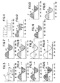
- FIG. 15 are given by way of example. Other sampling/modification methods could also be utilized with the invention. Note also that for clarity of explanation in these figures that the input sample is converted to digital by a leading edge sample and hold circuit (left edge), while the output sample is converted to analog by a trailing edge conversion circuit (right edge). Alternate conversion circuits could be utilized if desired. For ease of comprehension, no interpolation is used in figures 3-15.
- the second plurality of digital samples 120 can be interpolated to reduce distortion caused by replication or deletion of the selected digital sample 22 if appropriate.
- a second digital converter 114 then generates an output signal 100 from the second plurality of digital samples 120 over the second duration of time 113 (again the inclusion of this convertor is dependent on the nature of the output signal). In the example shown, this produces a signal having substantially the same first frequency when clocked or reproduced at the new speed provided that the rate of occurrence of altered samples 22 relative to the input sample rate corresponds to the ratio between the first 13 and second 113 duration times.
- either the digital converter 14 or the digital converter 114 may be optional in the event that either the input signal 10 or the output signal 100 is a digital signal of suitable signal content to allow for acceptable modification. Otherwise, oversampling would normally be appropriate.
- the selected digital sample(s) 22 is added (fig 6) to the sampled version 20 of the input signal 10 to provide pitch correction to facilitate the prior or subsequent decrease of the duration time.
- the selected digital sample(s) 22 is removed (fig 13) from the sampled version 20 of the input signal 10 to provide pitch correction to facilitate the prior or subsequent increase of the duration time. This will be discussed more extensively later, especially with respect to FIGURES 16-18.
- the signal modification circuit 50 adds or subtracts to the apparent alpha length of the input signal 10 according to the difference ratio in order to produce the output signal 100.
- this signal modification circuit 50 would begin with digital signals or a digital sampling replication 15 of an analog signal. This signal modification circuit 50 then repeats (to add or expand) or deletes (to subtract or compress) from these samples in order to alter the input signal 10 to an output signal 100 in accord with the set difference ratio. (Note again that a digital signal might, like an analog signal, have to be digitally over sampled to achieve acceptable distortion performance.)
- a more sophisticated signal modification circuit 50 could average or linearly or otherwise interpolate the modified samples in order to optimize the functioning of the device in certain applications.
- interpolation algorithms may be advantageous from a performance standpoint.
- examples of other algorithms would be polyphase subfiltering, higher order Lagrange polynomial interpolation, and finite impulse response low-pass filtering.
- the added sample may also be advantageous for the added sample to be of some value other than the value of the immediately preceding sample.
- the signal modification circuit 50 would contain a delay length preferably of the variable type, the length of which must at least allow for the appropriate shifting of the signals to add or subtract whole cycles. Specifically, the maximum shift between the input signal 10 and the output signal 100 should be within the effective delay length of the available memory. Further, to provide for a smooth output signal 100, the present invention preferably uses a memory delay longer than this period in order to provide for a seamless operation.
- the present invention accomplishes this with less than the amount of memory otherwise needed by comparing a first and second signal in order to reset the information in the memory (as later described) to add or delete blocks or cycles thus to provide for a seamless integration of the signals.
- the more memory that is available the more time can pass before the device is reset subject to an ascertainable artifact override.
- an even greater memory would allow an operator to delete or add blocks, cycles, or multiple cycles of signal information with no pitch change.
- the delay could be a single memory if variable taps were available and the signal was actively followed through such variable taps by the signal modification circuit 50.
- Changing over between effectively two separate memory delay lengths 56, 57 is preferred, which delay lengths are each long enough to provide for the later described resetting, because of the way the design evolved.
- a single memory delay element was originally used. Later, a second memory delay element was added, since this was, at the time, the easiest way to accommodate the needed later described cross fade reset operation.
- one memory circuit would be actively utilized in real time by the signal modification circuit, while the other memory preferably would continue to be updated with input signal data.
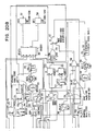
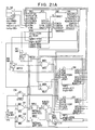
- An example of this is the two stretch cell embodiments set forth in FIGURES 20 and 21.
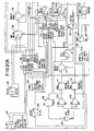
- FIGURES 16 and 20-21 include two effective memory lines 56 and 57 together with two modification circuits 60 and 61.
- FIGURE 16 utilizes two separate RAM memories while FIGURES 20 and 21 utilize a single RAM memory, with two different address spaces allocated respectively to two stretch cells to allow resetting.
- the memory lines 56, 57 are preferably RAM memory circuits. These circuits provide for a delay necessary for the processing to occur.
- the length of these memory circuits is chosen in order to optimize the performance of the overall circuitry while at the same time preferably minimizing expense.
- the selection of length is normally a compromise between excessive delay versus the ascertainable artifacts which might occur during resetting at an earlier than appropriate time or resetting at too high a rate. In general, changing over more quickly reduces information loss. However, changing over too quickly results in unacceptable artifacts, so a compromise is chosen. Also, in general, optimization of performance is determinative of the preferable length for the memories 56, 57, even though theoretically an infinite memory length could be used.
- memory lengths of from 38 mS to 149 mS are more than sufficient for a normal audio signal. This memory is sufficiently long to allow for the smooth crossover between memories 56, 57 while at the same time storing sufficient samples so as to support the typically experienced maximum time between crossovers. Note that the length of the memory is a design choice. For example, there are frequent times of audio silence in a television talk show.
- the memory could be reset during these times of silence, thus not dumping or repeating any audio information.
- the length of memory required is the expected length between silences multiplied by the conversion factor. For example, for .4 seconds between silences at ten percent expansion or compression, 40 mS of memory is typically required. Further example in a symphony orchestra a memory technically long enough to work may produce artifacts due to too frequent resets. A longer memory accompanied by a reset prevention control would therefore be used, preferably delaying resetting to a time of silence or otherwise when least artifacts would occur.
- An additional example would be with television video content wherein there are frequent times of static images and/or screen changes. These can be located with a motion detector. By adding or deleting frames thus changing over video during these times, video artifacts are reduced to a minimum. Further, if the signals of any nature are compressed or expanded prior to signal modification and the sampling rate is high enough, and acceptable reset opportunities occur with sufficient frequency, conversion can occur with low average throughout delay. It is, therefore, important to recognize that the invention can be optimized for a given signal by slightly altering its specific implementation.
- the modification circuits 60, 61 add or-subtract samples to the signals contained within the memories 56, 57, respectively. This modification of the samples can occur while the samples are being fed into the memories 56, 57, while they are being removed from the memories, or otherwise.
- the rate of digital sampling is normally dependent on the complexity and frequency of the signals. In general, the more complex the signal and/or the more this conversion ratio is removed from unity, the more samples will be needed. The reason for this is that using too few samples in a complex, high frequency conversion will result in excessive distortion. For example with a 30Mhz computer square wave high/low input signal, three samples per clock period would be sufficient to slow the signal down to 20Mhz (see fig 11). However, with a 20kHz audio signal, a sample rate much higher relative to signal frequency would be necessary to provide a 5 percent expansion without audible artifacts (see representative fig 12). This is because the information content of the computer signal is accurately conveyed solely by the on/off state. Thus the digital sampling rate must be carefully selected in view of the signals, both input 10 and output 100, as well as the difference ratio 51 to be encountered.
- Changing over between the signal of the first memory 56 and the signal of the second memory 57 is accomplished by a reset control 65.
- the reset control 65 operates, the signal modification circuit 50 changes over to the previously inactive memory circuit to remit the output signal 100.
- the other once active memory at the same time becomes disconnected from the output. The result is to increase or decrease the effective length of the overall memory.
- the reset control 65 operates by comparing two signals in order to determine their similarity, with the changing over between the signals in memory occurring based on this similarity.
- the purpose of the reset control 65 is to maintain the overall throughout delay within acceptable limits.
- the signals being compared typically should include a delayed signal and another signal, which may itself be also delayed or not.
- samples are being removed and a signal is effectively output from memory faster than it is being input. For this reason, the reset point could be at maximum delay or at the end of the memory.
- a delayed signal at this point is then compared to the relatively undelayed signal that is being used by the modification circuit for changeover to maximum delay.
- samples are being added and a signal is effectively output from memory more slowly than it is being input.
- the reset point could be at minimum delay, or at the beginning of the memory.
- a relatively undelayed signal at this point (which could even be the input signal) is then compared to a relatively delayed signal that is being used by the modification circuit for changeover to minimum delay.
- the reset control 65 could be a computer that has as a signal feed of only the input signal, which the computer compares with time shifted versions of such signal to operate this reset control 65 through analytical analysis, essentially comparing two versions of the single input signal for similarity; this with no other direct connection to any signal modification circuit signal input or output.
- the reset control could be a computer that compares a plurality of signals over a range at one end of a memory with a second plurality of signals over a range at the other end of a memory, with the reset occurring between the two most similar signals.
- the signals being compared would be developed from an analysis of a plurality of signals. While the resulting reset might not produce the maximum amount of available memory (i.e., be to the end of the memory), complex signals would be effectively processed. Therefore, depending on circuit design, the signals compared for similarity may vary from that disclosed herein. The key is that the signals have a statistical probability of being similar and are representative of signals displaced from each other in the memory.
- the reset control could compare: a) the signal at the output of one memory 56, 57 to the input of the other memory 56, 57; b) the output 100 to the input 10; or, c) otherwise as desired or appropriate.
- the input signal and output from the active memory are compared.
- the output from the active memory and the signal delayed relative to this output are compared.
- the reset control 65 in ascertaining similarity, preferably, compares the signals for: a) relative slope between signals; and, b) relative amplitude between signals. These are compared to preset thresholds. Signals meeting the criteria of low relative slope and amplitude include periods of no information (i.e., silence in audio). Video signals could be compared for scene change points for the addition/deletion of frames in a video image in an alternative embodiment. Video signals could also be compared for static video images, in an alternative embodiment.
- the Algorithms used to extract signal comparison information must be selected consistent with the type of coding used.
- the compared signals be examined for similarity in as many characteristics as practical. For example, the use of zero crossover in a similar direction alone in a reset control could produce an artifact if one signal was a high frequency signal at that point while the other was a low frequency signal. Similarly, least relative slope alone could cause unacceptable artifacts to critical listeners of an orchestra if resetting occurs more rapidly than is absolutely necessary. Look forward and look back comparisons would thus preferably be utilized in the reset control 65 so as to optimize the overall comparison with time displaced information as well as current signal status. Further, the reset control 65 would preferably include an override in response to these overall comparisons in order to limit unneeded resets, thus optimizing the comparison procedure. In general, the more comparison attributes are included, the better the operation of the reset control 65.
- the reset function is often accompanied by a repeat of signal (pitch increase mode; samples removed) or discard of signal (pitch decrease mode; samples added).
- the active signal modification circuit uses signal data at a somewhat faster rate than it is being fed into the memory line 56 (the actual rate dependent on the expansion ratio). This causes the active signal modification circuit 60 to relatively advance up the memory line 56. While this is occurring, the reset control 65 is examining two signals for similarity. In the embodiment shown, the signal being output by the active signal modification circuit 60 and the signal at the circuits reset position are compared (as depicted by dotted lines in all figures). When the signals are similar (or when the active memory line 56 is used up), a reset occurs. This causes the other memory line 57 to return to the relative reset point and other modification circuit 61 to become active.
- this reset causes a certain portion 58 of the input signal 10 to be processed for a second time repeating this data at the output of the signal modification circuit 50.
- the input signal 10 is periodic, and an integral number of signal periods is repeated, the artifact is acceptable.
- the actual repeat would normally be one or more complete cycle of the input signal.
- the actual reset would repeat only a fraction of the actual signal content. In fact, this fraction is typically equal to the compression factor.
- the active signal modification circuit uses signal data at a slower rate than it is being fed into the memory line 56. This causes the active signal modification circuit 60 to relatively retreat down the memory line 56. While this is occurring, again the reset control 65 is examining two signals for similarity. In the embodiment shown, the signal being utilized by the active signal modification circuit 60 and the signal at the circuits reset or input position (dotted lines in all figures) are compared. When the signals are similar (or when the active memory line 56 is used up), a reset occurs. This causes the other memory line 57 and other modification circuit 61 to become active.
- the reset causes a certain portion 59 of the input signal 10 to be never processed, thus deleting this data from the output of the signal modification circuit 50.
- the input signal is Periodic, and an integral number of periods is deleted, the artifact is acceptable, especially given the ways described herein of reducing its noticeability.
- this example uses two memory lines 56, 57 and two modification circuits 60, 61 with a single sample rate for clarity of explanation.
- the memory lines 56, 57 could be combined, a single modification circuit could be utilized, only increase or decrease, or both increase and decrease, could be provided in a single circuit, the processing could occur in real time for pitch shifting and other signals could be compared for reset control.
- the signals in memory could be clocked out at higher or slower rates than being input, thus providing the alteration of the alpha length of the input signal without movement of the signals to the modification circuits (which in both compress and contract could be located at the end of two individually differing clocked memory lines). Examples of these and other embodiments are given here and elsewhere in this application.
- the resetting increases or decreases the effective length of the overall memory with acceptable artifacts by changing over between effective memories as previously described.
- the reset control 65 changes over between the relative memories 56, 57 as described.
- the previously inactive memory 56, 57 is reset at the time of changeover, thus extending its relative length.
- this switchover preferably occurs when all important channels are similar at the same time, thus minimizing perceived stereo or spatial phase shift. This reduces the loss of stereo or spatial imaging.
- This correlation is preferably occasioned by logically connecting each channel associated reset control 66 to the reset control 65 for cooperative signals in order to provide for comparisons of their respective signals similarity.
- the reset control 65 has not operated near to either end of an operative total memory length, changing over is forced; preferably based on some sort of optimization formula (ideally computerized).
- This preferable forcing recognizes that a particular memory length may run out of its ability to compensate for the delay between the compared signals prior to the compared signals being similar (as previously set forth), and thus might produce annoying artifacts.
- the signals might be forced independently according to individual parameters. One example of this would be if one channel had high frequency (such as a fife), and the other channel had low frequency (such as drums). The optimum forcing times for each respective channel might not be coincidental.
- the low channel might be forced at a different time from the high channel: if the channels were forced simultaneously, there could be high frequency cancellation and/or loss of imaging. It is therefore appropriate for the forcing to be under the control of some logic specifically designed for the nature of the signals. For example with off/on computer signals, the two channels could be forced independently: Each according to its own parameters. However, for a stereo audio system or for an audio signal synchronized with a video image, care must be taken not to destroy the imaging and/or synchronization. The channels must therefore be correlated to insure that this does not happen.
- the circuitry in FIGURES 16 and 20-21 have a reset control 65 which compares the intermediate signals in the modification circuits 60, 61 for similarity with the reset control 65 operating a cross fade control 70 to change over between modification circuits 60, 61.
- the input signal 10 is a signal stored for production over a first length of time.
- This input signal 10 has frequency related information thereon.
- An example would be a television or audio signal from a video cassette recorder or other storage means.
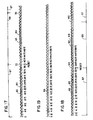
- a simplified stylistic version of this input signal 10 is shown in FIGURE 3 (in the actual signal, a more complex waveform would normally occur; see FIGURE 12 for example). For reasons not particularly important to this example, it is desired to extend this example signal by substantially 5.6 percent without altering the apparent frequency content thereon.
- FIG. 15 are given by way of example. Other sampling/modification methods could also be utilized with the invention. Note also that for clarity of explanation in these figures that the input sample is converted to digital by a leading edge sample and hold circuit (left edge), while the output sample is converted to analog by a trailing edge conversion circuit (right edge). Alternate conversion circuits could be utilized if desired. For ease of comprehension, no interpolation is used in figures 3-15.
- the first step of this example is to replicate the input signal 10 of FIGURE 3 into digital form.
- this is accomplished by a pulse amplitude analog to digital converter 14.
- An example of this digital sampled signal is shown in FIGURE 4.
- pulse amplitude modulation is shown for this digital example, it is to be understood that other coding methods could be utilized without deviating from the claimed invention. Examples include PWM, PEM, PDM, PCM, PPM, PNM, PFM, PLM, and PIM.
- the analog signal 10 has been replicated into digital form 20 through the use of PAM, specifically thirty-six (36) digital samples 21, each having an amplitude.
- PAM specifically thirty-six
- this 5.6 percent is the equivalent of two samples of our example digital wave 20 of FIGURE 4 (it is necessary then to add two digital samples 22 to the input signal 10 in order to frequency compensate such signal).
- the sampling rate preferably must be high enough so as to allow the insertion (or deletion) of a sample 21 in the replication of the output signal 100, without introducing unacceptable distortion.
- the samples 20 be inserted (or deleted) where any artifacts would be least noticeable. In the case of a significant expansion (or contraction), the samples would preferably be spread out over the entire length of the wave form (see fig 12 for a representative complex wave form).
- Our example signal is a sine wave with the samples added at the point of least slope; the peaks 23 of the positive wave and negative wave, respectively. Therefore, needing only two samples, at these two points the signal modification circuit 50 inserts an additional sample 24 in both the positive and negative series of digital samples 21. This produces the modified digital signal 25 of FIGURE 6.
- a modified signal without highlighting is shown in FIGURE 7, now representative of the sampling 120 of the output signal 100. Note that FIGURE 7 has a peak sample repeated.
- the output signal 100 can be played back at a clock rate some 5.6 percent higher than the input signal 10 in FIGURE 3 while at the same time producing a signal having the same frequency content to the observer as existed in the input signal 10.
- the compression/expansion factor is equal to the inverse of the number of samples between peaks. In the more general case, where such a simple relationship did not exist between waveform period and pitch shift factor, it typically would not necessarily be possible to arbitrarily select the more favorable points for sample insertion or deletion.
- the difference between our example input 10 and output signal 100 is some 5.6 percent. However, any difference, including this 5.6 percent, is cumulative for each cycle of the input signal 10. For this reason, the memory necessary to perform the function of modifying the input signal 10 into the output signal 100 can be computed by multiplying the number of repetitive cycles by the difference time factor, by 5.6 percent in our example. This adds up very quickly to a significant amount, an amount requiring ever increasing memory.
- the applicant's invention uses the reset control 65 to change over between effective memory points in the signal modification circuit 50 so as to reuse the same effective memory repeated times.
- This reset control circuit 65 operates when the two signals being compared are similar within prescribed parameters as previously set forth. It then changes over between similar signals.
- An example of the comparison can be seen in FIGURE 17.
- This figure represents a circuit adding samples to a first analog signal 63 to produce a second, expanded analog signal 64.
- the first analog signal 63 and the second analog signal 64 both have a positive going similar slope, same direction, zero crossings at the same location 70. If one immediately reset the signals, and began the cycle anew at this time, an individual to whom the signal 100 was addressed would not notice any significant artifacts. For this reason, the switchover could compensate for the increasing phase lag between the signals with memory having a finite length.
- the cost of this in FIGURE 17 is the loss of one cycle of the first analog signal 63, which one cycle would never be produced to be perceived by the individual.
- this resetting is most easily accomplished by changing over between two memory lines 56, 57 accompanied by a resetting of the second memory line (as was further described in respect to FIGURE 16). While this compromises the input signal 10 information, this resetting significantly reduces the amount of memory necessary for the device to operate. More importantly, even if infinite memory were available, resetting must still be done. Otherwise, the desired effect of time compression or expansion would be completely cancelled. As an example of this, memory line 56 would be utilized for the time 67 with memory line 57 utilized for the time 68 to produce the output 64.
- FIGURE 18 represents a circuit deleting samples of a first analog signal 63 to produce a second compressed analog signal 65.
- This figure is a graph comparing the first analog signal 63 and the second analog signal 65 and illustrating the reset 140 of the signals at a common amplitude, similar frequency signal peak.
- the two memory lines 56, 57 would preferably be utilized alternately to produce the output 64 without seams.
- the invention finds particular application in MPEG audio and video compression (figs 22-23).
- MPEG audio and video compression (figs 22-23).
- MPEG MPEG audio and video compression
- the MPEG compression standard provides for encoding a unique number in the compressed audio and video data stream every 0.7 seconds or so at the time of compression. Upon subsequent decompression, these numbers are presented to the audio and video system decoders in order to facilitate a comparison of the audio number to the video number in order to allow the two to be brought back into relative synchrony at these periodic times by manipulating the video via video frame memories. This still, however, can produce ascertainable artifacts tiring or objectionable to the observer. Further, multiple frame video memory buffers are necessary to allow the needed frame comparisons to repeat or drop identical frames. This memory is expensive and the processing complex.
- the present invention can be utilized to re-synchronize the signals, thus eliminating the tiring and objectionable artifacts. Further, the multiple frame video delay and complex comparisons of the MPEG standards are not needed even though better synchronization is achieved. The invention accomplishes this by effectively speeding up or slowing down the audio signal(s) to synchronize it to the video, and does so without any pitch change.
- the invention preferably utilizes the automatic reference signals to accomplish this synchronization.
- the two preferred reference signals which are encoded at the time of MPEG compression are SCR (System Clock Reference) and PTS (Presentation Time Stamps), the details of which may be found in the MPEG specification standards published by ISO/IEC.
- SCR System Clock Reference
- PTS Presentation Time Stamps
- Other compression standards suffer from the same problems and may make use of these or similar SCR or PTS type schemes, which will be referred to collectively here as time flags.
- the encoded time flags thus represent the starting time at which a particular video frame and its associated audio signal(s) arrive at the encoder, and/or are to be played back together from the decoder.
- the invention of this application can be utilized in conjunction with a continuously variable audio delay to provide a better audio to video synchronization than in the present MPEG frame drop/frame repeat standard. Further, this is achieved at a lower cost.
- the invention preferably accomplishes this by adding samples to the audio to allow the audio to be slowed down to re-synchronize the signals (in the instance of advanced audio), or deleting samples to allow the audio to be sped up to re-synchronize the signals (in the instance of delayed audio).
- the signal modification circuit may be used by itself or in conjunction with a frame drop/frame repeat device.
- the video signal to be output from the receiver's video decoder precedes the audio. This delay allows the processing of the video signal to synchronize the eventual audio signal output with the video signal. (The resulting correspondingly advanced audio is delayed in the receiver to allow synchronization to be achieved.) As previously discussed, this synchronization is accomplished in the MPEG standard by dropping or repeating video frames.
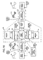
- the MPEG input signals are fed from the normal compressor encoder circuits 160 in the customary mode of transmission (tape, transmitter, receiver, cable, etc.) to a modified adaptive decoder 190.
- the adaptive decoder 190 shown is modified from a customary MPEG adaptive decoder in that the adaptive decoder 190 has only slightly over a single field of video memory 191, and the use of this optional memory is to allow for an unusual override reset of the signal modification circuit 150 (as later described).
- the customary MPEG demodulator has at least two frames of memory, which memory is actively used for audio re-synchronization.
- the video signal in this modified device is directed through the adaptive decoder 190 to produce an output video signal in the customary manner according to with MPEG standards, except that it trails the audio signal by approximately two frames (this due to the deletion of the audio to video synchronization from the video signal path).
- the audio input signals 10 are fed through the adaptive decoder 190 to convert such signals to customary -form.
- the audio input signals 10 are, however, then passed through a signal modification circuit 150 in order to add or subtract samples to synchronize the audio to the video signals.
- This synchronization is accomplished by adding or deleting samples in the audio input signal 10 according to the invention.
- the audio delay time may be adjusted, without pitch changes, to enable proper synchronization with the video. This is preferred in that it occurs at a much lower hardware/software cost than a video memory or memory system would produce. This would normally be an intermittent procedure accomplished after relative synchronization was lost, typically during times of major video changes.
- the relative video delay allows re-synchronization without the introduction of objectionable artifacts.
- the unique number transmitted every .7 seconds in the MPEG system could provide a reference for automatic synchronization by altering the signal modification circuit 150 to add or subtract samples as needed under the control of the interface comparing logic 170.
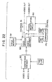
- the control of the audio delay may be either a feed forward (fig 22) or a feed back arrangement (fig 23).
- the time flags of the video and audio which are output from their respective decoders are compared to determine the amount of delay which the audio needs to achieve synchronization with the video. This delay is coupled to the audio delay control to cause it to change to the desired amount.
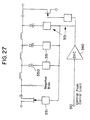
- the audio and video signals are fed through a compression encoder 250 subject to the time flag 251 in the customary manner. However, on decompression while the video signal 10 is fed through a customary rate convertor 253, the audio signal 10 is fed through the signal modification circuit 50 to re-synchronize the signals.
- a comparitor 255 analyzes the video flag and audio flag to automatically control the sample addition/deletion of the modification circuit 50.
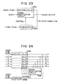
- the time flags of the audio output from its decoder are delayed by the same amount as the audio is delayed in the variable memory.
- the audio time flag and audio may of course be delayed in the same, or separate matching memories.
- the video time flag corresponding to the output from the variable memory is compared to determine the amount of synchronization error of the audio relative to the video. This error is coupled to the audio delay control to cause it to change to correct the error.
- the audio signal 10 is fed to a modified signal modification circuit 50A, a circuit that actively acts on the audio flag in addition to the audio signal 10.
- the comparitor 255A then compares this delayed audio flag to the video flag in order to control the signal modification circuit 50A to re-synchronize the audio output to the video.
- control of multiple sound channel timing for any multiple sound channel application may be implemented by itself with the variable delay capability of the present invention. This is especially true because of the precise delay control which may be achieved in the present invention. Multiple sound channel timing control is, however, quite cost effective. Further, it is very useful to include such correction as an additional capability of audio to video synchronization circuitry.
- Another invention showing correlation of multiple audio channels for applications where audio and video are transmitted over different paths is shown in Cooper U.S. Patent 4,703,355 which is incorporated herein by reference with respect to its prior art teachings and in particular, signal correlation and generation of control signals responsive thereto.
- the invention may be utilized in an entertainment or other system to provide faster or slower than normal recording or replay of audio, and if desired associated video.
- Other information may be utilized as well, with the teachings herein being just as applicable to storage or replay of any information having a frequency parameter where it is desired to alter the time duration without altering the frequency.
- FIGURE 25 shows a system in which a physical storage medium 300 along with its associated scanning mechanism is controlled by the user by providing a varying reference to the scanning mechanism.
- the physical storage medium be a digital video disk such as a common optical CD device which utilizes a spindle motor to rotate the storage medium, which is the disk, and a laser and optical scanning head which make up the scanning mechanism.
- the servo mechanism for the spindle motor with a variable frequency reference signal which is provided by a Numerically Controlled Oscillator (N.C.O.) 305 which frequency is controlled by the user interface and control logic 310.
- N.C.O. Numerically Controlled Oscillator
- the user interface and control logic 310 also interactively controls the optical scanning head position, receiving positional data from the scanning mechanism (which alternatively may be provided via the recorded data) to perform start, stop, record, play, search and other functions normally provided. In this manner the recording or playback of the audio and/or video data may be controlled to take place at different and variable rates.
- positional data from the scanning mechanism (which alternatively may be provided via the recorded data) to perform start, stop, record, play, search and other functions normally provided.
- the recording or playback of the audio and/or video data may be controlled to take place at different and variable rates.
- any storage device may be adapted to implement the invention, including analog video disk recorders, analog audio tape recorders, DAT recorders, video optical disc recorders, video tape recorders, rotating magnetic disk recorders (such as computer disk drives), film based recorders and projectors, solid state memory including semiconductor memories, charged coupled device memories, switched calculation recorders, and three dimensional solid memories such as laser addressed crystal lattices. All of these storage device types have in common a mechanical, electronic, optical or combination scanning mechanism which selects where within the physical storage medium the data is stored or read. It is by controlling the rate at which this scanning mechanism operates that the rate of storage or reading is made variable.
- the invention may be utilized with record only, playback only or record and playback versions.
- the rate of reading or writing may not be successful over a very large range by simply causing the scanning mechanism to operate at different rates.
- the data is stored in a form which takes on many analog characteristics.
- the data is stored as alternating light polarization of a layer of material.
- the data is read back by the laser beam which beam is directed to an electro-optical sensor or converter thus providing an electrical signal which varies in response to the laser light.
- the frequency and intensity characteristics of the laser light are altered, thereby altering the frequency and intensity characteristics of the corresponding electronic signal.
- FIGURE 27 shows an adaptive filter network which is operable to change the filter compensation to fit the playback or record speed.
- the filter utilizes varactor diodes 350 to provide a voltage variable capacitance, thus changing the filter frequency characteristics.
- the voltage which is applied to the varactors is provided by a digital analog converter 360, which in turn is loaded with the appropriate digital number for the particular speed being used, which loading is accomplished by the user interface and control logic 310.
- Linearization or voltage mapping circuits 351 are provided at the input and output of the filter and at the varactors 350 to compensate for any non-linearities therein.
- the filter operates to reduce the high frequency content of the data signal to a proper level, the amount of reduction depending on the speed of the data.
- the adaptive demodulator 320 After the audio and video is demodulated by the adaptive demodulator 320, it is required to pitch correct the audio under control of the user interface and control logic 310 as by the circuitry described in the preceding figures, and to convert the rate of the video to standard rates in order that it may be viewed on standard viewing devices.
- the video rate converters 330 are known in the art as frame synchronizers. While it is possible for frame synchronizers to operate self contained, improved operation and lower cost may be obtained by providing the rate converter with information and control from the user interface and control logic, and additional features such as video special effects may be provided as well.
- the pitch converter 340 is as set forth in this present application.
- a two-way pitch shifter has been implemented with a Star Semiconductor SPROC IC and is shown in FIGURE 20.
- the SPROC IC is available from Star Semiconductor of San Jose, California and is of type SPROC-1400-50PG132C. Information on the use of this and similar ICS is available from Star.
- the preferred embodiment would use type SPROC-1400-50MQ144C, which functions similarly, but at a lower cost.
- FIGURE 20 is directly compatible with the SPROC Development System Part Number SPPROClab tm version 1.25, P/N SDS-1001-03 with SPROClab version 1.25 patch B, P/N SDS-1002-01B.
- Figure 20 is a schematic representation of digital signal processing.
- the frequency converter system is specifically designed for a stereo audio source having a 20kHz input bandwidth.
- the audio input signals 10 are sampled at 48kHz sample rate.
- the 50Mhz P/N SPROC-1400-50PG132C SPROC chip is used for processing. Left and right channels are processed identically, and in parallel. Some control blocks (or “cells" in the Star Semiconductor nomenclature) are common to both left and right.
- ST_INO 202 accepts Format 2 stereo input samples which are provided by a Crystal Semiconductor CS5326 A-D Convertor. Output 1 is the right channel, and output 2 is the left. This discussion will concentrate on the left channel and common processing.
- Stretch cells ST1 200 and ST2 201 each perform the stretch/interpolate or compress/interpolate functions in stereo. Most of the time, only one is actually connected to the output. Two are required during a reset operation, as will be described below. ST1 200 and ST2 201 perform reads and writes to RAM circular buffers 56, 57 in order to accomplish the stretch or compress function.
- Two-way stretch cells are used at STI 200 and ST2 201.
- delay might start at 35 mS and decrease until a cross-fade reset event occurs. At reset, delay is returned to or near 35 mS, and the process repeats.
- the pitch decrease mode delay starts at or near zero, and increases until a cross fade reset event occurs. At reset, delay returns to near zero, and the process repeats. Thus, while in the pitch decreasing mode some program material is discarded at a reset, in the pitch increasing mode some program material is repeated.
- ST1 200 and ST2 201 output stereo samples at the 35 mS memory candidate reset point for splice match testing.
- the left channel outputs of ST1 200 and ST2 201 connect to the output via MFADE0 207.
- a ramp signal is applied to MFADE 207 to accomplish the fade.
- This ramp is formed by MMV1 211, MMV2 212, MINUS3 217, and INT2 214.
- MMV1 211, MMV2 212, MINUS3 217, and INT2 214 Depending on direction, either one-shot MMV1 211 or MMV2 212 produces a pulse 3072 samples (64mS) long.
- Integrator-INT2 214 forms the ramp.
- Subtraction cell 217 causes alternate ramps to be in different directions.
- INT2 214 output takes values between 0 and 1.0. Ramp length of 64mS was determined empirically. Too short a ramp produces an abrupt transition; too long produces an echo effect.
- a reset is initiated only when the differences between input and output slope and instantaneous amplitude are within certain limits, in order to make the cleanest splice practicable.
- Amplitude and slope match for the left channel are measured by MINUS2 221; first-difference cell DIFF2 222; and cells p1 223 and p3 224.
- SW1 225 selects the appropriate stretch cell output.
- p1 223 or p3 224 produces an active low reset signal whenever the magnitude at the cell input is below a certain threshold. These thresholds are continuously scaled according to signal level and slope. The intent is to require the same relative match, independent of amplitude or instantaneous frequency.
- This scaling is performed by SUM1-213; DIFF3 230; and, peak detectors PD0 231 and PD1 232.
- SUM1 213 performs full wave rectification, of each input, and sums the results to produce its output.
- PD0 231 and PD1 232 gains set the degree of match required.
- p7 237 emits a one sample width active low reset pulse. This is steered to the appropriate one-shot and stretch cells by logic formed by threshold detector GT1 238; INV1 240; Or2 241; and, OR3 242. Delay cells DELAY2 245 and DELAY4 246 are intended to correct timing misalignments.
- Cells that are specific to right channel operation are DELAY3 249, SW2 250, MINUS4 251, SUM4 252, p9 235, p10 236, DIFF4 252, DIFF5 253, PD2 254, PD3 255, RECT5, and p11 256.
- p11 is not functional in this design.
- Stereo output is accomplished by parallel port output cells OUT0 257 and OUT1 258.
- Output parallel data is subsequently converted to serial format by hardware interfaced to the SPROCtm parallel port. This serial data is then converted to 8X oversampling format by a Nippon Precision Circuits Ltd. SM5813APT IC. The oversampled data is passed to two Analog Devices, Inc.
- AD1862N digital-to-analog converter ICS to produce analog stereo audio output.
- Control of pitch correction factor and reset point is accomplished by changing the output levels of VR98 259 and VR99 260.
- VR98 level should be 2 (reset point of 2 samples delay), and VR99 level should be 1.0.
- VR98 level should be 2, and VR99 level should be 0.0.
- AMP3 261 scales the pitch correction factor output from VR99 260 and passes it to stretch cells ST1 200 and ST2 201.
- the output levels of VR98 259 and VR99 260 may be modified by the SPROC development system, both during the initial building of the design, and during operation. Ideally, pitch correction factor and reset point may be controlled by an embedded microprocessor communicating with one of the SPROC ports. Serial output cell OUT3 262 sends the fade ramp signal to a PCM56 DAC on the development board. This signal is a useful telltale of system performance. This port is not supported in the production board hardware, but this signal could be sent to the probe port (which will be supported) by modifying the SPROC tm initialization code.
- the memories of ST1 200 and ST2 201 in FIGURE 20 are arranged as circular buffers. Data is continuously written to the inputs such that each buffer contains the most recent samples for a period equal to the memory length. In fact, the contents of each me single memory. SW3 205 and SW4 206 would no longer be required. It may also be possible to combine the functions of OUTA with OUTC and OUTB with OUTD, respectively. A minimum of two separate memory outputs would still be needed, of course, to support the signal comparison and reset operations. Further code savings could be obtained by eliminating the NDXIN and NDXOUT outputs from ST1 200 and ST2 201, or a combined cell, since these outputs are not used in this embodiment.
- FIGURE 21 shows pitch correction integrated with the delay function.
- the pitch corrector functions of FIGURE 20 are essentially cascaded intact with the delay function, except with the added ability to force or inhibit stretch cell 200 and 201 reset.
- Cell TAUO 263 operates directly on the input samples, and produces delay. TAUO 263 changes delay in a manner identical to stretch cell operation, but without resetting. TAUO 263 utilizes external memory. Since pitch shift occurs during delay change, TAUO 263 output is passed to ST1 200 and ST2 201 for pitch correction. TAUO 263 also performs parallel port access for stereo sample output and micro-controller interface. Stereo output samples from MFADEO 207 are passed to TAUO 263 for output via the SPROC tm parallel port.
- Cell CN0 264 coordinates operation of the delay and pitch correction cells.
- TAUO 263 reports its current delay to CNO 264.
- CNO 264 reads stretch cell index values. The indices from the active stretch cell are selected by SW5 265 and SW6 266.
- CNO 264 computes the current stretch cell delay, and adds the TAUO 263 delay to determine total delay. This total delay is passed to TAUO 263 for parallel port output to the micro-controller.
- Target delay is read from the micro-controller via TAUO 263. If total delay equals target delay, CN0 264 holds TAUO 263, ST1 200, and ST2 201, by writing zero to the slew factor inputs of those three cells, and inhibiting stretch cell reset.
- the stretch cells are initialized. If the delay change direction should be opposite of the previous change, it is likely that the initial stretch cell delay is too far removed from the appropriate reset point.
- CNO 264 sweeps the reset point values in the vicinity of the nominal for a period of 0.5 Sec, enabling a high probability of a splice. When this splice occurs, the stretch cell becomes initialized without an abrupt transition. Then, CN0 264 outputs complementary slew values to TAUO 263, ST1 200, and ST2 201. This produces delay change and pitch correction at a ten percent rate.
- ST1 200 and ST2 201 delay the slew factor by the same amount as the audio, to maintain temporal registration between the two.
- the total delay change occurs primarily during fades, because of the pitch corrector reset action. Delay change during each fade is generally of slightly more than 20 mS in size.
- the stretch cells are held, and TAUO 263 also at a 0.2 percent rate, without pitch correction, until the target is reached. If TAUO's 263 delay reaches zero before the target is reached, TAUO 263 is held, and the stretch cell delay is decreased at a 0.2 percent rate, without pitch correction, until the total delay is correct.
- the delay also at a 0.2 percent rate, without stretch cell initialization or pitch correction.
- the minimum delay target is one sample (1/48000 Sec.), not counting data converter decimation or interpolation filter delay.
- Dump mode is enabled by requesting zero delay.
- TAUO 263, ST1 200, and ST2 201 are reset to minimum delay and held. Requesting a non-zero delay target causes normal operation to resume.
- control via the SPROC tm development system is substituted for microprocessor control.
- ST1 200 and ST2 201 could also be combined in a manner similar to that described for ST1 200 and ST2 201 of FIGURE 20.
- SW3 205 and SW4 206 would not be needed.
- a single output NDXIN would be required, which would also eliminate SW5 265.
- a smoother fade ramp could be obtained by using a raised-cosine function, instead of a linear ramp.
- a watchdog timer function would be incorporated into the hardware and code.
- the preferred embodiment is described as operating on the input signal, a signal which is being produced at a first speed, to produce the output signal, which output is subsequently clocked at the second speed to provide the same frequency based information. It would be possible to modify the order of conversion without deviating from the invention as claimed. For example, one could modify the frequency conversion system of the present invention to create a second plurality of signals clocked at different speed prior to frequency conversion. This could occur, for example, on a taped system operated at a higher or lower speed than normal to produce a signal in need of frequency conversion.
- the input signal would be reproduced at the output signals' speed in order to create a version of the second plurality of signals.
- An example of this would be to speed up an audio tape recorder to produce a pitch changed version of the audio stored thereon.
- the frequency converter system of the present application would act upon this sped up version of the second plurality of signals in order to modify the number of samples therein to meet the requirements of the new clock speed and thus produce the pitch shifted output signal. No further memory would be needed if the sampling rate was high enough.
- samples would be added in order to lower the pitch of the output signal to match the pitch of the input signal originally recorded on the tape recording, and thus produce a output signal having a frequency substantially the same frequency as the input signal.
- the frequency converter of this invention can therefore operate before, during or after the clock shift of the input signal.
- the clock shift can be upwards (compression), downward (expansion), or the same as (dropout compensation, profanity dump) at any time during recording, storage, and/or replication of the input signal.
- homomorphic signal processing such as homomorphic signal processing, sub-band coding, Fourier transformation , power spectrum estimation 1 , correlation, or measurement of relative second or higher order differences
- homomorphic deconvolution followed by linear filtering, may be applied to speech signals to separate pitch and other components 1,2. Separated parameters could be respectively compared.
- sub-band coding a speech, image, or other waveform is divided into several frequency bands, where each band is coded separately 3 . Individual sub-band components could be respectively compared.
- spectrum amplitude and/or phase components as resolved by Fourier transformation could be compared. In the case of correlation, signals could be compared over some length considerably larger than that of the comparison used in the present embodiment.
- NBVM Narrow band voice modulation
Landscapes
- Engineering & Computer Science (AREA)
- Signal Processing (AREA)
- Multimedia (AREA)
- Human Computer Interaction (AREA)
- Acoustics & Sound (AREA)
- Marketing (AREA)
- Computer Networks & Wireless Communication (AREA)
- Computational Linguistics (AREA)
- Quality & Reliability (AREA)
- Health & Medical Sciences (AREA)
- Audiology, Speech & Language Pathology (AREA)
- Physics & Mathematics (AREA)
- Business, Economics & Management (AREA)
- Signal Processing For Digital Recording And Reproducing (AREA)
- Television Signal Processing For Recording (AREA)
- Superconductors And Manufacturing Methods Therefor (AREA)
- Window Of Vehicle (AREA)
- Valve-Gear Or Valve Arrangements (AREA)
- Two-Way Televisions, Distribution Of Moving Picture Or The Like (AREA)
- Compression, Expansion, Code Conversion, And Decoders (AREA)
- Transmission Systems Not Characterized By The Medium Used For Transmission (AREA)
- Reduction Or Emphasis Of Bandwidth Of Signals (AREA)
- Measurement Of The Respiration, Hearing Ability, Form, And Blood Characteristics Of Living Organisms (AREA)
- Measurement And Recording Of Electrical Phenomena And Electrical Characteristics Of The Living Body (AREA)
- Radar Systems Or Details Thereof (AREA)
Claims (21)
- Verfahren zur Umwandlung eines Eingangssignals, das frequenzbezogene Information über eine erste Zeitspanne reproduzieren lässt, zu einem Ausgangssignal, das im Wesentlichen dieselbe frequenzbezogene Information über eine zweite, unterschiedliche Zeitspanne reproduzieren lässt,
wobei besagtes Verfahren das Ermitteln des Verhältnisses zwischen der zweiten Zeitspanne und der ersten Zeitspanne, Oversampling (Überablastung) mindestens eines der Eingang- oder Ausgangssignale und dann Änderung der Alpha-Länqe des Ausgangssignals durch besagtes Verhältnis durch Addieren oder Subtrahieren mindestens eines der besagten Oversamples (Überabtastproben) in der Alpha-Länge des überabgetasteten Signals umfasst,
wobei die Alpha-Länge als die Zeidauer eines zusammenhängenden Signalblocks, ausschließlich irgendwelcher Reset-Operationen, definiert ist;
wobei mindestens besagte Zahl von Samples (Proben) in einem Speicher mit einem begrenzten Wert. gespeichert werden und weiter das Resetting (Rücksetzen) des Speichers nach Vergleichen der zwei Signale umfassend:und wobei das Ausgangssignal mit dem Eingangssignal verglichen wird, um Resetting auszulösen. - Verfahren nach Anspruch 1, dadurch gekennzeichnet, dass Änderung der Alpha-Länge des Ausgangssignals digitales Abtasten eines des Eingangs- oder Ausgangssignals und dann Modifizieren der Zahl von Samples des digital abgetasteten Signals einschließt.
- Verfahren nach Anspruch 2, dadurch gekennzeichnet, dass die Zahl von Samples vor Speicherung in den Speicher modifiziert wird
- Verfahren nach Anspruch 2, dadurch gekennzeichnet, dass die Zahl von Samples nach Speichorung in den Speicher modifiziert wird.
- Verfahren nach Anspruch 1, dadurch gekennzeichnet, dass mindestens besagte Zahl von Samples in zwei Speichern gespeichert, wird, die Ausgänge und Reset-Bereiche aufweisen, wovon einer aktiv für das Modifizieren der Zahl von Samples ist, wobei besagtes Resetting der Speicher das Umschalten vom aktiven Speicher zum Roset-Bereich im inaktiven Speicher einschließt.
- Verfahren nach Anspruch 5, dadurch gekennzeichnet, dass der Ausgang des inaktiven Speichers mit dem aktiven Speicher verglichen wird, um Resetting auszulösen.
- Verfahren nach Anspruch 1, dadurch gekennzeichnet, dass besagte Umschaltung ein Zeit-Fading einschließt.
- Verfahren nach Anspruch 1, wovon das Ausgangssignal mit einem assoziierten Kanal synchronisiert sein muss und gekennzeichnet durch Änderung der Alpha-Länge des Ausgangssignals, um es ebenso mit dem assoziierten Kanal zu synchronisieren.
- Verfahren mach Anspruch 8, dadurch gekennzeichnet, das das Ausgangssignal frequenzbezogene Information relativ zu einer ersten Zeitreferenz nach einem assoziierten Signal auf einem zweiten Kanal zeitgesteuert hat, der relative zur selben Zeitreferenz zeitgesteuert ist, welches Signal auf das assoziierte Signal an einem beliebigen Punkt in Istzeit, synchronisiert werden könnte oder auch nicht,
Ermitteln des Zeitdifferentials zwischen dem Ausgangssignal und dem assoziierten Signal auf dem zweiten Kanal und dann Änderung der Alpha-Länge des Ausgangssignals als Reaktion auf das Zeitdifferential. - Verfahren nach Anspruch 1, das Erlangen eines Eingangssignals, Oversampling (Überabtastung) besagten Eingangssignals durch ein Oversampling-Digital Codierverfahrengerät zum Produzieren eines ersten Satzes digitaler Samples,
Ermitteln des Verhältnisses zwischen der zweiten Zeitspanne und der ersten Zeitspanne, Modifizieren besagten ersten Satzes besagter digitaler Samples in einem Signalmodifikationsschaltkreis in Übereinstimmung mit besagtem Differenzverhältnis um einen zweiten Satz digitaler Samples zu produzieren,
Umwandeln besagten zweiten Satzes digitaler Samples zum Produzieren eines Ausgangssignals mit einer Alpha-Länge, die im signalmodifikationsschaltkreis durch besagtes Differenzverhältnis geändert wurde und Übersenden besagten Ausgangssignals einschließt. - Verfahren nach Anspruch 10, dadurch gekennzeichnet, dass Änderung der Alpha-Länge des Ausgangssignals digitales Sampling (Abtasten) eines Eingangs- oder Ausgangssignals und danach Modifizieren der Zahl der Samples des digital abgetasteten Signals mit mindestens besagter Zahl von Samples und Speicherung in zwei Speichern mit Ausgangs-und Resetbereichen einschließt,
wovon einer zum Modifizieren der Zahl von Samples aktiv ist, wobei besagte zwei Speicher begrenztes Werte-Resetting des speichers nach dem Vergleich von zwei Signalumschaltungen aufweisen, wobei besagtes Resetting der Speicher das Umschalten vom aktiven Speicher auf den Resetbereich des inaktiven Speichers einschließt. - Verfahren nach Anspruch 11, dadurch gekennzeichnet, dass ein erster Modifikationsschaltkreis vorhander ist, der mit einem der Speicher assoziiert ist und ein zweiter Signalmodifikationsschaltkreis mit dem anderen der Speicher assoziiert ist und das durch den zusätzlichen Schritt von Überblenden zwischen dem Ausgang des ersten Signalmodifikationsschaltkreises und dem zweiten signal modifikations schaltkreis gekennzeichnet ist.
- Verfahren nach Anspruch 1, wobei besagtes Ändern der Alpha-Länge des Ausgangssignals einschließt :A) Eingeben eines Eingangssignals in einen Speicher,B) Verwenden des Speichers zum Produzieren erster und zweiter Signale von einer Lokalität, Position oder einem Punkt, die/der den Antang bzw. das Ende des Speichers umfassen könnte.C) Verwenden besagten ersten Signals zum Produzieren eines Ausgangssignals für eine erste Zeitspanne, das den Speicher von einem Resetbereich durchläuft, während gleichzeitig zwei Signale vergleichen werden.D) Umschalten auf Verwenden besagten zweiten Signals zum Produzieren des Ausgangssignals, wenn besagte zwei Signale ähnlich sind, wobei besagtes zweite Signal in besagtem Regelbereich beginnt,E) Verwenden besagten zweiten Signals zum Produzieren eines Ausgangssignals für eine zweite Zeitspanne, das den Speicher von einem Resetbereich durchläuft, während gleichzeitig besagte zwei Signale auf Ähnlichkeit verglichen werden,F) Umschalten auf Verwenden besagten ersten Signals zum Produzieren eines Ausganssignals, wenn besagte zwei Signale ähnlich sind, wobei besagtes erste Signal in besagtem Resetbereich beginnt,G) danach Wiederholen der Schritte C bis F, um die offensichtliche Verzögerungerungslänge des speichers zu ändern.
- Verfahren nach Anspruch 13, wobei der Speicher eine einzelne RAM speicherplatzanordung umfasst.
- Verfahren nach Anspruch 13, wobei das erste signal eine Alpha-Länge aufweist und wobei Verwenden besagten ersten Signals zum Produzieren eines Ausgangssignals einen Modifikationsschaltkreis einschließt, der die Alpha-Länge des besagten ersten Signals modifiziert, um das Ausgangssignal zu produzieren.
- Verfahren nach Anspruch 13, wobei das zweite Signal eine Alpha-Länge aufweist und wobei Verwenden besagten zweiten Signals zum Produzieren eines Ausgangssignals einen Modifikationsschaltkreis einschließt, der die Alpha-Länge des besagten zweiten Signals modifiziert, um das Ausgangssignal zu produzieren.
- Verfahren nach Anspruch 15, wobei die Alpha-Länge komprimiert ist und dadurch gekennzeichnet, dass besagtes erste Signal an den Anfang des Speicher rückgesetzt ist.
- Verfahren nach Anspruch 16, wobei die Alpha-Länge kontrahiert ist und dadurch gekennzeichnet, dass besagtes erste Signal ans Ende des Speicher rückgesetzt ist.
- Verfahren nach Anspruch 16, wobei die Alpha-Länge komprimiert ist und dadurch gekennzeichnet, dass das zweite Signal an den Anfang des Speichers rückgesetzt ist.
- Verfahren nach Anspruch 16, wobei die Alpha-Länge kontrahiert, ist und dadurch gekennzeichnet, dass besagtes zweite Signal ans Ende des Speichers rückgesetzt ist.
- Verfahren nach Anspruch 13, wobei besagte zwei Signale, die auf Ähnlichkeit verglichen werden, das Eingangs- und Ausgangssignal umfassen.
Priority Applications (1)
| Application Number | Priority Date | Filing Date | Title |
|---|---|---|---|
| EP07117659A EP1892840A3 (de) | 1994-10-12 | 1995-10-12 | Zeitkompression/-expansion ohne Intonationsveränderung |
Applications Claiming Priority (3)
| Application Number | Priority Date | Filing Date | Title |
|---|---|---|---|
| US08/322,069 US5920842A (en) | 1994-10-12 | 1994-10-12 | Signal synchronization |
| US322069 | 1994-10-12 | ||
| PCT/US1995/014631 WO1996012270A1 (en) | 1994-10-12 | 1995-10-12 | Time compression/expansion without pitch change |
Related Child Applications (1)
| Application Number | Title | Priority Date | Filing Date |
|---|---|---|---|
| EP07117659A Division EP1892840A3 (de) | 1994-10-12 | 1995-10-12 | Zeitkompression/-expansion ohne Intonationsveränderung |
Publications (3)
| Publication Number | Publication Date |
|---|---|
| EP0807304A1 EP0807304A1 (de) | 1997-11-19 |
| EP0807304A4 EP0807304A4 (de) | 2004-12-08 |
| EP0807304B1 true EP0807304B1 (de) | 2007-10-03 |
Family
ID=23253280
Family Applications (2)
| Application Number | Title | Priority Date | Filing Date |
|---|---|---|---|
| EP95939879A Expired - Lifetime EP0807304B1 (de) | 1994-10-12 | 1995-10-12 | Zeitkompression/-expansion ohne tonhöhenveränderung |
| EP07117659A Withdrawn EP1892840A3 (de) | 1994-10-12 | 1995-10-12 | Zeitkompression/-expansion ohne Intonationsveränderung |
Family Applications After (1)
| Application Number | Title | Priority Date | Filing Date |
|---|---|---|---|
| EP07117659A Withdrawn EP1892840A3 (de) | 1994-10-12 | 1995-10-12 | Zeitkompression/-expansion ohne Intonationsveränderung |
Country Status (6)
| Country | Link |
|---|---|
| US (9) | US5920842A (de) |
| EP (2) | EP0807304B1 (de) |
| AU (1) | AU684411B2 (de) |
| CA (1) | CA2202538C (de) |
| DE (1) | DE69535606D1 (de) |
| WO (1) | WO1996012270A1 (de) |
Families Citing this family (299)
| Publication number | Priority date | Publication date | Assignee | Title |
|---|---|---|---|---|
| US8352400B2 (en) | 1991-12-23 | 2013-01-08 | Hoffberg Steven M | Adaptive pattern recognition based controller apparatus and method and human-factored interface therefore |
| US5754250A (en) | 1992-02-18 | 1998-05-19 | Cooper; J. Carl | Synchronizing signal separating apparatus and method |
| US5486869A (en) | 1992-02-18 | 1996-01-23 | Cooper; J. Carl | Synchronizing signal separating apparatus and method |
| US5920842A (en) * | 1994-10-12 | 1999-07-06 | Pixel Instruments | Signal synchronization |
| EP0789968B1 (de) * | 1994-10-27 | 2003-03-05 | Index Systems, Inc. | System und methode zur fernladung von recorderprogrammierungsdaten in einem videosignal |
| AU5027796A (en) | 1995-03-07 | 1996-09-23 | Interval Research Corporation | System and method for selective recording of information |
| US6769128B1 (en) | 1995-06-07 | 2004-07-27 | United Video Properties, Inc. | Electronic television program guide schedule system and method with data feed access |
| US6388714B1 (en) * | 1995-10-02 | 2002-05-14 | Starsight Telecast Inc | Interactive computer system for providing television schedule information |
| CN1202658C (zh) | 1996-03-15 | 2005-05-18 | E盖德公司 | 录像节目索引和电子节目引导组合方法和选择节目的装置 |
| JP3216531B2 (ja) * | 1996-07-24 | 2001-10-09 | 三菱電機株式会社 | 再多重化装置および再多重化方法 |
| JP3528451B2 (ja) * | 1996-07-26 | 2004-05-17 | ソニー株式会社 | 電子番組ガイド表示制御装置及びその方法 |
| US6263507B1 (en) | 1996-12-05 | 2001-07-17 | Interval Research Corporation | Browser for use in navigating a body of information, with particular application to browsing information represented by audiovisual data |
| US5893062A (en) | 1996-12-05 | 1999-04-06 | Interval Research Corporation | Variable rate video playback with synchronized audio |
| JPH10262208A (ja) * | 1997-03-19 | 1998-09-29 | Sony Corp | 同期ずれ制御装置及び方法 |
| US6960133B1 (en) | 2000-08-28 | 2005-11-01 | Igt | Slot machine game having a plurality of ways for a user to obtain payouts based on selection of one or more symbols (power pays) |
| JP4062577B2 (ja) | 1997-07-21 | 2008-03-19 | ジェムスター ディベロプメント コーポレイション | 表示及び記録制御インタフェースのためのシステム及び方法 |
| US6069882A (en) * | 1997-07-30 | 2000-05-30 | Bellsouth Intellectual Property Corporation | System and method for providing data services using idle cell resources |
| US7349333B2 (en) * | 1997-07-30 | 2008-03-25 | At&T Delaware Intellectual Property, Inc. | Associated systems and methods for providing data services using idle cell resources |
| US5899969A (en) * | 1997-10-17 | 1999-05-04 | Dolby Laboratories Licensing Corporation | Frame-based audio coding with gain-control words |
| JP3501645B2 (ja) * | 1998-02-13 | 2004-03-02 | 富士通株式会社 | 放送映像録画装置 |
| US7185355B1 (en) | 1998-03-04 | 2007-02-27 | United Video Properties, Inc. | Program guide system with preference profiles |
| US7272298B1 (en) * | 1998-05-06 | 2007-09-18 | Burst.Com, Inc. | System and method for time-shifted program viewing |
| CN1867068A (zh) | 1998-07-14 | 2006-11-22 | 联合视频制品公司 | 交互式电视节目导视系统及其方法 |
| AR020608A1 (es) | 1998-07-17 | 2002-05-22 | United Video Properties Inc | Un metodo y una disposicion para suministrar a un usuario acceso remoto a una guia de programacion interactiva por un enlace de acceso remoto |
| ES2342593T3 (es) | 1998-07-17 | 2010-07-09 | United Video Properties, Inc. | Sistema de guia interactivo de programas de television que tienen multiples dispositivos dentro de una casa. |
| US6505348B1 (en) | 1998-07-29 | 2003-01-07 | Starsight Telecast, Inc. | Multiple interactive electronic program guide system and methods |
| US6233389B1 (en) | 1998-07-30 | 2001-05-15 | Tivo, Inc. | Multimedia time warping system |
| US8380041B2 (en) | 1998-07-30 | 2013-02-19 | Tivo Inc. | Transportable digital video recorder system |
| US8577205B2 (en) | 1998-07-30 | 2013-11-05 | Tivo Inc. | Digital video recording system |
| US7558472B2 (en) | 2000-08-22 | 2009-07-07 | Tivo Inc. | Multimedia signal processing system |
| US20020054752A1 (en) * | 1998-08-07 | 2002-05-09 | Anthony Wood | Video data recorder with personal channels |
| US6360053B1 (en) * | 1998-08-07 | 2002-03-19 | Replaytv, Inc. | Method and apparatus for fast forwarding and rewinding in a video recording device |
| US20010043795A1 (en) * | 1998-08-07 | 2001-11-22 | Anthony Wood | Video data recorder for recording predefined format shows |
| US7515896B1 (en) | 1998-10-21 | 2009-04-07 | Parkervision, Inc. | Method and system for down-converting an electromagnetic signal, and transforms for same, and aperture relationships |
| US6061551A (en) | 1998-10-21 | 2000-05-09 | Parkervision, Inc. | Method and system for down-converting electromagnetic signals |
| US6694128B1 (en) | 1998-08-18 | 2004-02-17 | Parkervision, Inc. | Frequency synthesizer using universal frequency translation technology |
| US6898762B2 (en) | 1998-08-21 | 2005-05-24 | United Video Properties, Inc. | Client-server electronic program guide |
| TW465235B (en) | 1998-09-17 | 2001-11-21 | United Video Properties Inc | Electronic program guide with digital storage |
| US6374225B1 (en) * | 1998-10-09 | 2002-04-16 | Enounce, Incorporated | Method and apparatus to prepare listener-interest-filtered works |
| US6061555A (en) | 1998-10-21 | 2000-05-09 | Parkervision, Inc. | Method and system for ensuring reception of a communications signal |
| US7236754B2 (en) | 1999-08-23 | 2007-06-26 | Parkervision, Inc. | Method and system for frequency up-conversion |
| US7039372B1 (en) | 1998-10-21 | 2006-05-02 | Parkervision, Inc. | Method and system for frequency up-conversion with modulation embodiments |
| US7027786B1 (en) | 1998-10-21 | 2006-04-11 | Parkervision, Inc. | Carrier and clock recovery using universal frequency translation |
| US6542722B1 (en) | 1998-10-21 | 2003-04-01 | Parkervision, Inc. | Method and system for frequency up-conversion with variety of transmitter configurations |
| US6560301B1 (en) | 1998-10-21 | 2003-05-06 | Parkervision, Inc. | Integrated frequency translation and selectivity with a variety of filter embodiments |
| US6370371B1 (en) | 1998-10-21 | 2002-04-09 | Parkervision, Inc. | Applications of universal frequency translation |
| US6813485B2 (en) | 1998-10-21 | 2004-11-02 | Parkervision, Inc. | Method and system for down-converting and up-converting an electromagnetic signal, and transforms for same |
| US20040210932A1 (en) * | 1998-11-05 | 2004-10-21 | Toshiaki Mori | Program preselecting/recording apparatus for searching an electronic program guide for programs according to predetermined search criteria |
| US6661422B1 (en) * | 1998-11-09 | 2003-12-09 | Broadcom Corporation | Video and graphics system with MPEG specific data transfer commands |
| US7982740B2 (en) | 1998-11-09 | 2011-07-19 | Broadcom Corporation | Low resolution graphics mode support using window descriptors |
| US6636222B1 (en) | 1999-11-09 | 2003-10-21 | Broadcom Corporation | Video and graphics system with an MPEG video decoder for concurrent multi-row decoding |
| US6738072B1 (en) | 1998-11-09 | 2004-05-18 | Broadcom Corporation | Graphics display system with anti-flutter filtering and vertical scaling feature |
| US7446774B1 (en) | 1998-11-09 | 2008-11-04 | Broadcom Corporation | Video and graphics system with an integrated system bridge controller |
| US6768774B1 (en) | 1998-11-09 | 2004-07-27 | Broadcom Corporation | Video and graphics system with video scaling |
| US6798420B1 (en) | 1998-11-09 | 2004-09-28 | Broadcom Corporation | Video and graphics system with a single-port RAM |
| US6853385B1 (en) | 1999-11-09 | 2005-02-08 | Broadcom Corporation | Video, audio and graphics decode, composite and display system |
| US6573905B1 (en) | 1999-11-09 | 2003-06-03 | Broadcom Corporation | Video and graphics system with parallel processing of graphics windows |
| US7168086B1 (en) * | 1998-11-30 | 2007-01-23 | Microsoft Corporation | Proxy for video on demand server control |
| US6804825B1 (en) * | 1998-11-30 | 2004-10-12 | Microsoft Corporation | Video on demand methods and systems |
| US6628302B2 (en) * | 1998-11-30 | 2003-09-30 | Microsoft Corporation | Interactive video programming methods |
| US6865746B1 (en) | 1998-12-03 | 2005-03-08 | United Video Properties, Inc. | Electronic program guide with related-program search feature |
| KR100310346B1 (ko) * | 1998-12-19 | 2001-11-05 | 윤종용 | 텔레비전과 휴대폰이 일체화된 텔레비전 휴대폰 |
| EP1057330B1 (de) * | 1998-12-23 | 2007-03-21 | Koninklijke Philips Electronics N.V. | Programmwiedergabeanlage |
| US7209725B1 (en) | 1999-01-22 | 2007-04-24 | Parkervision, Inc | Analog zero if FM decoder and embodiments thereof, such as the family radio service |
| US7006805B1 (en) | 1999-01-22 | 2006-02-28 | Parker Vision, Inc. | Aliasing communication system with multi-mode and multi-band functionality and embodiments thereof, such as the family radio service |
| US7966078B2 (en) | 1999-02-01 | 2011-06-21 | Steven Hoffberg | Network media appliance system and method |
| US6879817B1 (en) | 1999-04-16 | 2005-04-12 | Parkervision, Inc. | DC offset, re-radiation, and I/Q solutions using universal frequency translation technology |
| US6266643B1 (en) * | 1999-03-03 | 2001-07-24 | Kenneth Canfield | Speeding up audio without changing pitch by comparing dominant frequencies |
| US6853690B1 (en) | 1999-04-16 | 2005-02-08 | Parkervision, Inc. | Method, system and apparatus for balanced frequency up-conversion of a baseband signal and 4-phase receiver and transceiver embodiments |
| US6873836B1 (en) | 1999-03-03 | 2005-03-29 | Parkervision, Inc. | Universal platform module and methods and apparatuses relating thereto enabled by universal frequency translation technology |
| US7110435B1 (en) | 1999-03-15 | 2006-09-19 | Parkervision, Inc. | Spread spectrum applications of universal frequency translation |
| US7065162B1 (en) | 1999-04-16 | 2006-06-20 | Parkervision, Inc. | Method and system for down-converting an electromagnetic signal, and transforms for same |
| US7693230B2 (en) | 1999-04-16 | 2010-04-06 | Parkervision, Inc. | Apparatus and method of differential IQ frequency up-conversion |
| US7110444B1 (en) | 1999-08-04 | 2006-09-19 | Parkervision, Inc. | Wireless local area network (WLAN) using universal frequency translation technology including multi-phase embodiments and circuit implementations |
| US6934759B2 (en) * | 1999-05-26 | 2005-08-23 | Enounce, Inc. | Method and apparatus for user-time-alignment for broadcast works |
| US8295406B1 (en) | 1999-08-04 | 2012-10-23 | Parkervision, Inc. | Universal platform module for a plurality of communication protocols |
| US7072390B1 (en) | 1999-08-04 | 2006-07-04 | Parkervision, Inc. | Wireless local area network (WLAN) using universal frequency translation technology including multi-phase embodiments |
| US7054296B1 (en) | 1999-08-04 | 2006-05-30 | Parkervision, Inc. | Wireless local area network (WLAN) technology and applications including techniques of universal frequency translation |
| AU4200600A (en) * | 1999-09-16 | 2001-04-17 | Enounce, Incorporated | Method and apparatus to determine and use audience affinity and aptitude |
| JP3450237B2 (ja) * | 1999-10-06 | 2003-09-22 | 株式会社アルカディア | 音声合成装置および方法 |
| US7155735B1 (en) | 1999-10-08 | 2006-12-26 | Vulcan Patents Llc | System and method for the broadcast dissemination of time-ordered data |
| US8250617B2 (en) * | 1999-10-29 | 2012-08-21 | Opentv, Inc. | System and method for providing multi-perspective instant replay |
| US9668011B2 (en) | 2001-02-05 | 2017-05-30 | Avago Technologies General Ip (Singapore) Pte. Ltd. | Single chip set-top box system |
| US6538656B1 (en) | 1999-11-09 | 2003-03-25 | Broadcom Corporation | Video and graphics system with a data transport processor |
| US6975324B1 (en) | 1999-11-09 | 2005-12-13 | Broadcom Corporation | Video and graphics system with a video transport processor |
| US8913667B2 (en) | 1999-11-09 | 2014-12-16 | Broadcom Corporation | Video decoding system having a programmable variable-length decoder |
| US7082171B1 (en) | 1999-11-24 | 2006-07-25 | Parkervision, Inc. | Phase shifting applications of universal frequency translation |
| DE69909849T2 (de) * | 1999-11-24 | 2004-05-27 | Stmicroelectronics Asia Pacific Pte Ltd. | Unterdrückung von alias-störungen in algorithmen für audio-effekten |
| WO2001040887A1 (en) | 1999-12-02 | 2001-06-07 | Senvid, Inc. | Method, system and service model for remote recording of television programs |
| US6963734B2 (en) | 1999-12-22 | 2005-11-08 | Parkervision, Inc. | Differential frequency down-conversion using techniques of universal frequency translation technology |
| US6665338B1 (en) * | 2000-01-05 | 2003-12-16 | Motorola, Inc. | Circuitry for converting a sampled digital signal to a naturally sampled digital signal and method therefor |
| JP4018859B2 (ja) * | 2000-01-19 | 2007-12-05 | パイオニア株式会社 | 情報再生装置 |
| US6634555B1 (en) | 2000-01-24 | 2003-10-21 | Parker Vision, Inc. | Bar code scanner using universal frequency translation technology for up-conversion and down-conversion |
| US6757682B1 (en) | 2000-01-28 | 2004-06-29 | Interval Research Corporation | Alerting users to items of current interest |
| JP3536792B2 (ja) * | 2000-02-28 | 2004-06-14 | ヤマハ株式会社 | 同期制御装置および同期制御方法 |
| US6724430B2 (en) * | 2000-03-29 | 2004-04-20 | Matsushita Electric Industrial Co., Ltd. | Sampling frequency converter, sampling frequency conversion method, video signal processor, and video signal processing method |
| US7010286B2 (en) | 2000-04-14 | 2006-03-07 | Parkervision, Inc. | Apparatus, system, and method for down-converting and up-converting electromagnetic signals |
| JP2001298719A (ja) * | 2000-04-17 | 2001-10-26 | Toshiba Corp | 情報再生方法および情報提供ビジネス方法 |
| US6314403B1 (en) * | 2000-05-11 | 2001-11-06 | Avid Technology, Inc. | Apparatus and method for generating a special effect on a digital signal |
| US6769985B1 (en) | 2000-05-31 | 2004-08-03 | Igt | Gaming device and method for enhancing the issuance or transfer of an award |
| US7554508B2 (en) | 2000-06-09 | 2009-06-30 | Parker Vision, Inc. | Phased array antenna applications on universal frequency translation |
| US6731313B1 (en) | 2000-06-23 | 2004-05-04 | Igt | Gaming device having touch activated alternating or changing symbol |
| US7695363B2 (en) | 2000-06-23 | 2010-04-13 | Igt | Gaming device having multiple display interfaces |
| US7699699B2 (en) | 2000-06-23 | 2010-04-20 | Igt | Gaming device having multiple selectable display interfaces based on player's wagers |
| US7886330B2 (en) * | 2000-06-30 | 2011-02-08 | Jlb Ventures Llc | Enhanced home entertainment system with removable long-term storage |
| DE60143662D1 (de) * | 2000-08-09 | 2011-01-27 | Thomson Licensing | Verfahren und system zum ermöglichen der umwandlung einer audiogeschwindigkeit |
| JP4785328B2 (ja) * | 2000-08-10 | 2011-10-05 | トムソン ライセンシング | オーディオ速度変換を可能にするシステムおよび方法 |
| CN100579203C (zh) | 2000-10-11 | 2010-01-06 | 联合视频制品公司 | 提供数据存储到点播媒体传递系统中服务器上的系统和方法 |
| US6739973B1 (en) | 2000-10-11 | 2004-05-25 | Igt | Gaming device having changed or generated player stimuli |
| US7454453B2 (en) | 2000-11-14 | 2008-11-18 | Parkervision, Inc. | Methods, systems, and computer program products for parallel correlation and applications thereof |
| US7010559B2 (en) | 2000-11-14 | 2006-03-07 | Parkervision, Inc. | Method and apparatus for a parallel correlator and applications thereof |
| US8677423B2 (en) * | 2000-12-28 | 2014-03-18 | At&T Intellectual Property I, L. P. | Digital residential entertainment system |
| JP2002217740A (ja) * | 2001-01-19 | 2002-08-02 | Sakai Yasue | 圧縮方法及び装置、伸長方法及び装置、圧縮伸長システム、記録媒体 |
| EP2028856A3 (de) | 2001-02-21 | 2011-01-05 | United Video Properties, Inc. | Systeme und Verfahren für interaktive Programmführer mit persönlichen Videoaufzeichnungsfunktionen |
| US7040983B2 (en) | 2001-03-21 | 2006-05-09 | Igt | Gaming device having a multi-round, multi-characteristic matching game |
| US6749502B2 (en) | 2001-03-21 | 2004-06-15 | Igt | Gaming device having a multi-characteristic matching game |
| US6813372B2 (en) * | 2001-03-30 | 2004-11-02 | Logitech, Inc. | Motion and audio detection based webcamming and bandwidth control |
| US7283954B2 (en) * | 2001-04-13 | 2007-10-16 | Dolby Laboratories Licensing Corporation | Comparing audio using characterizations based on auditory events |
| GB2379115A (en) * | 2001-08-21 | 2003-02-26 | Sony Uk Ltd | Introducing test signals into a data signal |
| US7901291B2 (en) * | 2001-09-28 | 2011-03-08 | Igt | Gaming device operable with platform independent code and method |
| US7666098B2 (en) * | 2001-10-15 | 2010-02-23 | Igt | Gaming device having modified reel spin sounds to highlight and enhance positive player outcomes |
| US7708642B2 (en) * | 2001-10-15 | 2010-05-04 | Igt | Gaming device having pitch-shifted sound and music |
| JP3823804B2 (ja) * | 2001-10-22 | 2006-09-20 | ソニー株式会社 | 信号処理方法及び装置、信号処理プログラム、並びに記録媒体 |
| CN1292588C (zh) * | 2001-10-29 | 2006-12-27 | 松下电器产业株式会社 | 图像声音同步装置 |
| US7085335B2 (en) | 2001-11-09 | 2006-08-01 | Parkervision, Inc. | Method and apparatus for reducing DC offsets in a communication system |
| US7072427B2 (en) | 2001-11-09 | 2006-07-04 | Parkervision, Inc. | Method and apparatus for reducing DC offsets in a communication system |
| US6879636B2 (en) * | 2001-12-10 | 2005-04-12 | Pelco Incorporated | Adaptive filter for suppressing repetitive high-frequency information in a video data stream |
| JP4166466B2 (ja) * | 2001-12-19 | 2008-10-15 | ソニー株式会社 | 無線通信システム及び無線通信方法、無線通信装置及びその制御方法、並びにコンピュータ・プログラム |
| US7310596B2 (en) * | 2002-02-04 | 2007-12-18 | Fujitsu Limited | Method and system for embedding and extracting data from encoded voice code |
| US7559076B2 (en) * | 2002-05-17 | 2009-07-07 | Broadcom Corporation | Sample rate reduction in data communication receivers |
| US6975848B2 (en) * | 2002-06-04 | 2005-12-13 | Parkervision, Inc. | Method and apparatus for DC offset removal in a radio frequency communication channel |
| US7321640B2 (en) | 2002-06-07 | 2008-01-22 | Parkervision, Inc. | Active polyphase inverter filter for quadrature signal generation |
| US7460584B2 (en) | 2002-07-18 | 2008-12-02 | Parkervision, Inc. | Networking methods and systems |
| US7379883B2 (en) | 2002-07-18 | 2008-05-27 | Parkervision, Inc. | Networking methods and systems |
| JP2004080674A (ja) * | 2002-08-22 | 2004-03-11 | Funai Electric Co Ltd | ディジタル放送/アナログ放送受信記録装置 |
| CA2439347A1 (en) * | 2002-09-03 | 2004-03-03 | Frederick Lietzman | Foot orthotic for supporting an arch of a foot, and related methods |
| US6982538B2 (en) * | 2002-09-06 | 2006-01-03 | Honeywell International Inc. | Methods and apparatus for generating a sinusoidal motor drive signal for a MEMS gyroscope |
| US7383509B2 (en) * | 2002-09-13 | 2008-06-03 | Fuji Xerox Co., Ltd. | Automatic generation of multimedia presentation |
| US8204353B2 (en) * | 2002-11-27 | 2012-06-19 | The Nielsen Company (Us), Llc | Apparatus and methods for tracking and analyzing digital recording device event sequences |
| US7493646B2 (en) | 2003-01-30 | 2009-02-17 | United Video Properties, Inc. | Interactive television systems with digital video recording and adjustable reminders |
| US7764758B2 (en) * | 2003-01-30 | 2010-07-27 | Lsi Corporation | Apparatus and/or method for variable data rate conversion |
| US20060051059A1 (en) | 2004-09-08 | 2006-03-09 | Krakirian Haig H | Video recorder having user extended and automatically extended time slots |
| US6760538B1 (en) * | 2003-04-21 | 2004-07-06 | Pioneer Digital Technologies, Inc. | Video recorder having user extended and automatically extended time slots |
| US7667710B2 (en) | 2003-04-25 | 2010-02-23 | Broadcom Corporation | Graphics display system with line buffer control scheme |
| US7499104B2 (en) * | 2003-05-16 | 2009-03-03 | Pixel Instruments Corporation | Method and apparatus for determining relative timing of image and associated information |
| US20070153125A1 (en) * | 2003-05-16 | 2007-07-05 | Pixel Instruments, Corp. | Method, system, and program product for measuring audio video synchronization |
| US20040255338A1 (en) * | 2003-06-13 | 2004-12-16 | Apple Computer, Inc. | Interface for sending synchronized audio and video data |
| DE10327057A1 (de) * | 2003-06-16 | 2005-01-20 | Siemens Ag | Vorrichtung zum zeitlichen Stauchen oder Strecken, Verfahren und Folge von Abtastwerten |
| US20060179107A1 (en) * | 2003-06-18 | 2006-08-10 | Yoshiaki Iwata | Network recording system, recording server, and terminal device |
| US9412123B2 (en) | 2003-07-01 | 2016-08-09 | The 41St Parameter, Inc. | Keystroke analysis |
| US7789748B2 (en) | 2003-09-04 | 2010-09-07 | Igt | Gaming device having player-selectable music |
| US7105736B2 (en) * | 2003-09-09 | 2006-09-12 | Igt | Gaming device having a system for dynamically aligning background music with play session events |
| US8063916B2 (en) | 2003-10-22 | 2011-11-22 | Broadcom Corporation | Graphics layer reduction for video composition |
| US8133115B2 (en) | 2003-10-22 | 2012-03-13 | Sony Computer Entertainment America Llc | System and method for recording and displaying a graphical path in a video game |
| US7984468B2 (en) | 2003-11-06 | 2011-07-19 | United Video Properties, Inc. | Systems and methods for providing program suggestions in an interactive television program guide |
| US7391884B2 (en) * | 2003-11-14 | 2008-06-24 | Microsoft Corporation | Correlative assessment between scanned and original digital images |
| US10999298B2 (en) | 2004-03-02 | 2021-05-04 | The 41St Parameter, Inc. | Method and system for identifying users and detecting fraud by use of the internet |
| US7030883B2 (en) * | 2004-03-10 | 2006-04-18 | Evans & Sutherland Computer Corporation | System and method for filtering a synchronization signal from a remote computer |
| JP4452136B2 (ja) * | 2004-03-30 | 2010-04-21 | 株式会社日立製作所 | データ同期再生装置及び端末装置 |
| JP4222250B2 (ja) * | 2004-04-26 | 2009-02-12 | ヤマハ株式会社 | 圧縮楽音データ再生装置 |
| US7333150B2 (en) * | 2004-05-14 | 2008-02-19 | Pixel Instruments Corporation | Method, system, and program product for eliminating error contribution from production switchers with internal DVEs |
| US8127242B1 (en) * | 2010-08-12 | 2012-02-28 | The United States Of America As Represented By The Secretary Of The Army | Graphic user interface and software for processing large size signal data samples in a small buffer using automatically adjusted decimation ratio |
| GB0412342D0 (en) * | 2004-06-03 | 2004-07-07 | Ibm | Convergent playback of buffered content to real-time content play |
| US7471337B2 (en) * | 2004-06-09 | 2008-12-30 | Lsi Corporation | Method of audio-video synchronization |
| CA2572306A1 (en) | 2004-07-02 | 2006-02-09 | Nielsen Media Research, Inc. | Methods and apparatus for identifying viewing information associated with a digital media device |
| JP2006084754A (ja) * | 2004-09-16 | 2006-03-30 | Oki Electric Ind Co Ltd | 音声録音再生装置 |
| US7585219B2 (en) | 2004-09-30 | 2009-09-08 | Igt | Gaming device having a matching symbol game |
| US20060071933A1 (en) | 2004-10-06 | 2006-04-06 | Sony Computer Entertainment Inc. | Application binary interface for multi-pass shaders |
| US8806533B1 (en) | 2004-10-08 | 2014-08-12 | United Video Properties, Inc. | System and method for using television information codes |
| US7342488B2 (en) * | 2004-10-13 | 2008-03-11 | Innvision Networks, Llc | System and method for providing home awareness |
| US8043155B2 (en) | 2004-10-18 | 2011-10-25 | Igt | Gaming device having a plurality of wildcard symbol patterns |
| CN101077006A (zh) | 2004-11-19 | 2007-11-21 | Tivo股份有限公司 | 用于先前播放内容的安全传输的方法和设备 |
| US20090064242A1 (en) * | 2004-12-23 | 2009-03-05 | Bitband Technologies Ltd. | Fast channel switching for digital tv |
| KR101286168B1 (ko) * | 2004-12-27 | 2013-07-15 | 가부시키가이샤 피 소프트하우스 | 오디오 신호처리장치, 방법 및 그 방법을 기록한 기록매체 |
| US7778173B2 (en) * | 2005-01-04 | 2010-08-17 | Cisco Technology, Inc. | Clock recovery algorithm for remultiplexing MPEG-2 SPTSs and/or MPTSs in the presence of network jitter |
| JP4406838B2 (ja) * | 2005-02-15 | 2010-02-03 | ソニー株式会社 | オーディオ入出力制御装置及びオーディオ入出力制御方法 |
| US7975283B2 (en) * | 2005-03-31 | 2011-07-05 | At&T Intellectual Property I, L.P. | Presence detection in a bandwidth management system |
| US8335239B2 (en) * | 2005-03-31 | 2012-12-18 | At&T Intellectual Property I, L.P. | Methods, systems, and devices for bandwidth conservation |
| US8306033B2 (en) * | 2005-03-31 | 2012-11-06 | At&T Intellectual Property I, L.P. | Methods, systems, and computer program products for providing traffic control services |
| US8098582B2 (en) * | 2005-03-31 | 2012-01-17 | At&T Intellectual Property I, L.P. | Methods, systems, and computer program products for implementing bandwidth control services |
| US8024438B2 (en) * | 2005-03-31 | 2011-09-20 | At&T Intellectual Property, I, L.P. | Methods, systems, and computer program products for implementing bandwidth management services |
| AU2005330569A1 (en) * | 2005-04-13 | 2006-12-07 | Pixel Instruments, Corp. | Method, system, and program product for measuring audio video synchronization independent of speaker characteristics |
| GB2438691A (en) * | 2005-04-13 | 2007-12-05 | Pixel Instr Corp | Method, system, and program product for measuring audio video synchronization independent of speaker characteristics |
| US9955205B2 (en) * | 2005-06-10 | 2018-04-24 | Hewlett-Packard Development Company, L.P. | Method and system for improving interactive media response systems using visual cues |
| US7636126B2 (en) * | 2005-06-22 | 2009-12-22 | Sony Computer Entertainment Inc. | Delay matching in audio/video systems |
| US8139924B2 (en) | 2005-07-07 | 2012-03-20 | Tivo Inc. | System and method for digital content retrieval |
| DE102005032080A1 (de) * | 2005-07-08 | 2007-01-11 | Siemens Ag | Verfahren zum Senden eines Mediadatenstroms und Verfahren zum Empfangen und Erstellen eines rekonstruierten Mediadatenstroms, sowie dazugehörige Sendevorrichtung und Empfangsvorrichtung |
| US20070019931A1 (en) * | 2005-07-19 | 2007-01-25 | Texas Instruments Incorporated | Systems and methods for re-synchronizing video and audio data |
| US8104054B2 (en) * | 2005-09-01 | 2012-01-24 | At&T Intellectual Property I, L.P. | Methods, systems, and devices for bandwidth conservation |
| US8701148B2 (en) * | 2005-09-01 | 2014-04-15 | At&T Intellectual Property I, L.P. | Methods, systems, and devices for bandwidth conservation |
| JP2007081534A (ja) * | 2005-09-12 | 2007-03-29 | Matsushita Electric Ind Co Ltd | 復号再生装置 |
| US20070124792A1 (en) * | 2005-11-30 | 2007-05-31 | Bennett James D | Phone based television remote control |
| US8340098B2 (en) * | 2005-12-07 | 2012-12-25 | General Instrument Corporation | Method and apparatus for delivering compressed video to subscriber terminals |
| WO2007075573A2 (en) * | 2005-12-16 | 2007-07-05 | The 41St Parameter, Inc. | Methods and apparatus for securely displaying digital images |
| US11301585B2 (en) | 2005-12-16 | 2022-04-12 | The 41St Parameter, Inc. | Methods and apparatus for securely displaying digital images |
| US8938671B2 (en) | 2005-12-16 | 2015-01-20 | The 41St Parameter, Inc. | Methods and apparatus for securely displaying digital images |
| JP4222366B2 (ja) * | 2005-12-19 | 2009-02-12 | 船井電機株式会社 | リモコン装置 |
| US9015736B2 (en) | 2005-12-29 | 2015-04-21 | Rovi Guides, Inc. | Systems and methods for episode tracking in an interactive media environment |
| US20070204118A1 (en) * | 2006-02-28 | 2007-08-30 | Sbc Knowledge Ventures ,L.P. | System and method of managing the memory content of a device |
| US7904056B2 (en) * | 2006-03-01 | 2011-03-08 | Ipc Systems, Inc. | System, method and apparatus for recording and reproducing trading communications |
| US7792815B2 (en) | 2006-03-06 | 2010-09-07 | Veveo, Inc. | Methods and systems for selecting and presenting content based on context sensitive user preferences |
| WO2007102147A2 (en) * | 2006-03-07 | 2007-09-13 | Bitband Technologies Ltd. | Personalized insertion of advertisements in streaming media |
| US8316394B2 (en) | 2006-03-24 | 2012-11-20 | United Video Properties, Inc. | Interactive media guidance application with intelligent navigation and display features |
| US8151327B2 (en) | 2006-03-31 | 2012-04-03 | The 41St Parameter, Inc. | Systems and methods for detection of session tampering and fraud prevention |
| US20070248314A1 (en) * | 2006-04-20 | 2007-10-25 | Televentions, Llc | Method and apparatus for controlled viewing of recorded television programs |
| US7965859B2 (en) | 2006-05-04 | 2011-06-21 | Sony Computer Entertainment Inc. | Lighting control of a user environment via a display device |
| US7880746B2 (en) * | 2006-05-04 | 2011-02-01 | Sony Computer Entertainment Inc. | Bandwidth management through lighting control of a user environment via a display device |
| US7822800B2 (en) * | 2006-05-19 | 2010-10-26 | Camco Produktions-Und Vertriebs Gmbh Fur Beschallungs-Und Beleuchtungsanlagen | Apparatus and method for performing a calculation operation |
| JP2008067294A (ja) * | 2006-09-11 | 2008-03-21 | Toshiba Corp | デジタル信号処理装置 |
| WO2008034490A1 (en) * | 2006-09-20 | 2008-03-27 | Nero Ag | Apparatus for providing digital data |
| JP4940888B2 (ja) * | 2006-10-23 | 2012-05-30 | ソニー株式会社 | オーディオ信号伸張圧縮装置及び方法 |
| US8491392B2 (en) | 2006-10-24 | 2013-07-23 | Igt | Gaming system and method having promotions based on player selected gaming environment preferences |
| DE602006015328D1 (de) * | 2006-11-03 | 2010-08-19 | Psytechnics Ltd | Abtastfehlerkompensation |
| US20080111887A1 (en) * | 2006-11-13 | 2008-05-15 | Pixel Instruments, Corp. | Method, system, and program product for measuring audio video synchronization independent of speaker characteristics |
| CN101548294B (zh) * | 2006-11-30 | 2012-06-27 | 杜比实验室特许公司 | 提取视频和音频信号内容的特征以提供信号的可靠识别 |
| US20080131075A1 (en) * | 2006-12-01 | 2008-06-05 | The Directv Group, Inc. | Trick play dvr with audio pitch correction |
| EP2104930A2 (de) | 2006-12-12 | 2009-09-30 | Evans & Sutherland Computer Corporation | System und methode zum ausgleichen des rgb-licht in einem monomodulator projektor |
| KR101334366B1 (ko) * | 2006-12-28 | 2013-11-29 | 삼성전자주식회사 | 오디오 배속 재생 방법 및 장치 |
| CN101242501B (zh) * | 2007-02-07 | 2011-07-27 | 深圳Tcl新技术有限公司 | 防止记录源意外改变的记录系统和方法 |
| US7801888B2 (en) | 2007-03-09 | 2010-09-21 | Microsoft Corporation | Media content search results ranked by popularity |
| US8418206B2 (en) | 2007-03-22 | 2013-04-09 | United Video Properties, Inc. | User defined rules for assigning destinations of content |
| US7477170B2 (en) * | 2007-05-09 | 2009-01-13 | Analaog Devices, Inc. | Sample rate converter system and method |
| KR101344485B1 (ko) * | 2007-07-09 | 2013-12-24 | 삼성전자주식회사 | 디지털 방송 수신기의 채널 전환 방법 및 그 장치 |
| US8842971B2 (en) * | 2007-07-31 | 2014-09-23 | The Directv Group, Inc. | Methods and apparatus to present audio and video at non-native rates |
| KR101138396B1 (ko) * | 2007-09-11 | 2012-04-26 | 삼성전자주식회사 | Iptv 단말기에서 컨텐츠 재생 방법 및 장치 |
| US8917972B2 (en) | 2007-09-24 | 2014-12-23 | International Business Machines Corporation | Modifying audio in an interactive video using RFID tags |
| US8339458B2 (en) * | 2007-09-24 | 2012-12-25 | International Business Machines Corporation | Technique for allowing the modification of the audio characteristics of items appearing in an interactive video using RFID tags |
| US7576665B2 (en) * | 2007-11-27 | 2009-08-18 | Amx Llc | System and method for receiving analog and digital input |
| US8051090B2 (en) * | 2007-12-28 | 2011-11-01 | Realtek Semiconductor Corp. | File management method of a ring buffer and related file management apparatus |
| US8700792B2 (en) * | 2008-01-31 | 2014-04-15 | General Instrument Corporation | Method and apparatus for expediting delivery of programming content over a broadband network |
| US20110023079A1 (en) * | 2008-03-20 | 2011-01-27 | Mark Alan Schultz | System and method for processing priority transport stream data in real time in a multi-channel broadcast multimedia system |
| US8358317B2 (en) | 2008-05-23 | 2013-01-22 | Evans & Sutherland Computer Corporation | System and method for displaying a planar image on a curved surface |
| US8989561B1 (en) | 2008-05-29 | 2015-03-24 | Rovi Guides, Inc. | Systems and methods for alerting users of the postponed recording of programs |
| US8488267B2 (en) * | 2008-06-06 | 2013-07-16 | Hewlett-Packard Development Company, L.P. | Sensor position adjustment with media velocity relative sample timing |
| US8702248B1 (en) | 2008-06-11 | 2014-04-22 | Evans & Sutherland Computer Corporation | Projection method for reducing interpixel gaps on a viewing surface |
| US8601526B2 (en) | 2008-06-13 | 2013-12-03 | United Video Properties, Inc. | Systems and methods for displaying media content and media guidance information |
| US8624908B1 (en) | 2008-06-27 | 2014-01-07 | Rovi Guides, Inc. | Systems and methods of transitioning from buffering video to recording video |
| US8752092B2 (en) * | 2008-06-27 | 2014-06-10 | General Instrument Corporation | Method and apparatus for providing low resolution images in a broadcast system |
| US20100037281A1 (en) * | 2008-08-05 | 2010-02-11 | Broadcom Corporation | Missing frame generation with time shifting and tonal adjustments |
| US8199833B2 (en) * | 2008-08-25 | 2012-06-12 | Broadcom Corporation | Time shift and tonal adjustment to support video quality adaptation and lost frames |
| US20100063825A1 (en) * | 2008-09-05 | 2010-03-11 | Apple Inc. | Systems and Methods for Memory Management and Crossfading in an Electronic Device |
| US8591308B2 (en) | 2008-09-10 | 2013-11-26 | Igt | Gaming system and method providing indication of notable symbols including audible indication |
| CN101978625B (zh) * | 2008-11-04 | 2014-07-30 | 汤姆森特许公司 | 用于多频道广播多媒体系统中的时刻表移动功能的系统和方法 |
| US8077378B1 (en) | 2008-11-12 | 2011-12-13 | Evans & Sutherland Computer Corporation | Calibration system and method for light modulation device |
| US10063934B2 (en) | 2008-11-25 | 2018-08-28 | Rovi Technologies Corporation | Reducing unicast session duration with restart TV |
| US20100169105A1 (en) * | 2008-12-29 | 2010-07-01 | Youngtack Shim | Discrete time expansion systems and methods |
| CN102292769B (zh) * | 2009-02-13 | 2012-12-19 | 华为技术有限公司 | 一种立体声编码方法和装置 |
| JP4550932B2 (ja) * | 2009-02-27 | 2010-09-22 | 株式会社東芝 | 放送受信システムおよびその制御方法 |
| US9112850B1 (en) | 2009-03-25 | 2015-08-18 | The 41St Parameter, Inc. | Systems and methods of sharing information through a tag-based consortium |
| US8352629B2 (en) * | 2009-03-26 | 2013-01-08 | 25-Seven Systems, Inc. | Media stream capture, modification, and forwarding |
| US9166714B2 (en) | 2009-09-11 | 2015-10-20 | Veveo, Inc. | Method of and system for presenting enriched video viewing analytics |
| US9014546B2 (en) | 2009-09-23 | 2015-04-21 | Rovi Guides, Inc. | Systems and methods for automatically detecting users within detection regions of media devices |
| WO2011071928A2 (en) * | 2009-12-07 | 2011-06-16 | Pixel Instruments Corporation | Dialogue detector and correction |
| KR101802238B1 (ko) * | 2010-02-23 | 2017-11-29 | 삼성전자주식회사 | 휴대용 단말기에서 입체 영상 데이터를 생성하기 위한 장치 및 방법 |
| US9357244B2 (en) * | 2010-03-11 | 2016-05-31 | Arris Enterprises, Inc. | Method and system for inhibiting audio-video synchronization delay |
| US10786736B2 (en) | 2010-05-11 | 2020-09-29 | Sony Interactive Entertainment LLC | Placement of user information in a game space |
| JP4988022B2 (ja) * | 2010-09-30 | 2012-08-01 | 株式会社東芝 | 映像表示装置及び音声出力制御方法 |
| US9361597B2 (en) | 2010-10-19 | 2016-06-07 | The 41St Parameter, Inc. | Variable risk engine |
| US9736524B2 (en) | 2011-01-06 | 2017-08-15 | Veveo, Inc. | Methods of and systems for content search based on environment sampling |
| US9342817B2 (en) | 2011-07-07 | 2016-05-17 | Sony Interactive Entertainment LLC | Auto-creating groups for sharing photos |
| US9641826B1 (en) | 2011-10-06 | 2017-05-02 | Evans & Sutherland Computer Corporation | System and method for displaying distant 3-D stereo on a dome surface |
| US10754913B2 (en) | 2011-11-15 | 2020-08-25 | Tapad, Inc. | System and method for analyzing user device information |
| US9967621B2 (en) | 2011-12-15 | 2018-05-08 | Rovi Technologies Corporation | Dynamic personalized program content |
| US8805418B2 (en) | 2011-12-23 | 2014-08-12 | United Video Properties, Inc. | Methods and systems for performing actions based on location-based rules |
| US8460090B1 (en) | 2012-01-20 | 2013-06-11 | Igt | Gaming system, gaming device, and method providing an estimated emotional state of a player based on the occurrence of one or more designated events |
| US9633201B1 (en) | 2012-03-01 | 2017-04-25 | The 41St Parameter, Inc. | Methods and systems for fraud containment |
| US9521551B2 (en) | 2012-03-22 | 2016-12-13 | The 41St Parameter, Inc. | Methods and systems for persistent cross-application mobile device identification |
| US8904446B2 (en) * | 2012-05-30 | 2014-12-02 | Verizon Patent And Licensing Inc. | Method and apparatus for indexing content within a media stream |
| US9245407B2 (en) | 2012-07-06 | 2016-01-26 | Igt | Gaming system and method that determines awards based on quantities of symbols included in one or more strings of related symbols displayed along one or more paylines |
| US8740689B2 (en) | 2012-07-06 | 2014-06-03 | Igt | Gaming system and method configured to operate a game associated with a reflector symbol |
| WO2014022813A1 (en) | 2012-08-02 | 2014-02-06 | The 41St Parameter, Inc. | Systems and methods for accessing records via derivative locators |
| WO2014078569A1 (en) | 2012-11-14 | 2014-05-22 | The 41St Parameter, Inc. | Systems and methods of global identification |
| JP6486833B2 (ja) | 2012-12-20 | 2019-03-20 | ストラブワークス エルエルシー | 三次元拡張オーディオを提供するシステム及び方法 |
| US20140250482A1 (en) * | 2013-03-01 | 2014-09-04 | Prime Image Delaware, Inc. | System and method for removing a pause in a delayed remote broadcast interview |
| US9351023B2 (en) * | 2013-03-15 | 2016-05-24 | Echostar Technologies L.L.C. | Output of broadcast content with portions skipped |
| US20140379710A1 (en) | 2013-06-19 | 2014-12-25 | International Business Machines Corporation | Pattern based video frame navigation aid |
| US10902327B1 (en) | 2013-08-30 | 2021-01-26 | The 41St Parameter, Inc. | System and method for device identification and uniqueness |
| US10720153B2 (en) * | 2013-12-13 | 2020-07-21 | Harman International Industries, Incorporated | Name-sensitive listening device |
| US9264656B2 (en) | 2014-02-26 | 2016-02-16 | Rovi Guides, Inc. | Systems and methods for managing storage space |
| US10091312B1 (en) | 2014-10-14 | 2018-10-02 | The 41St Parameter, Inc. | Data structures for intelligently resolving deterministic and probabilistic device identifiers to device profiles and/or groups |
| EP3026668A1 (de) * | 2014-11-27 | 2016-06-01 | Thomson Licensing | Vorrichtung und Verfahren zur Erzeugung visueller Inhalte aus einem Audiosignal |
| GB201506328D0 (en) * | 2015-04-14 | 2015-05-27 | D3 Technologies Ltd | A system and method for handling video data |
| JP6448527B2 (ja) * | 2015-12-10 | 2019-01-09 | キヤノン株式会社 | 周波数制御装置、モータ駆動装置および光学機器 |
| JP6346206B2 (ja) * | 2016-01-14 | 2018-06-20 | ファナック株式会社 | ブロック時間表示手段を有する数値制御装置 |
| DE102016107206A1 (de) * | 2016-04-19 | 2017-10-19 | Technisat Digital Gmbh | Verfahren zum Aufzeichnen von Medieninhalt mittels einer Empfangseinrichtung sowie eine Empfangseinrichtung |
| US10237593B2 (en) * | 2016-05-26 | 2019-03-19 | Telefonaktiebolaget Lm Ericsson (Publ) | Monitoring quality of experience (QoE) at audio/video (AV) endpoints using a no-reference (NR) method |
| US10477333B1 (en) * | 2016-11-29 | 2019-11-12 | Amazon Technologies, Inc. | Audio placement algorithm for determining playback delay |
| US9942072B1 (en) | 2017-01-27 | 2018-04-10 | Harris Corporation | Communications device with adaptive demodulator for PSK and FSK modulations and related methods |
| US10797784B2 (en) * | 2017-10-31 | 2020-10-06 | Space Systems/Loral, Llc | Satellite with regenerative processor |
| US10924809B2 (en) | 2017-12-05 | 2021-02-16 | Silicon Beach Media II, Inc. | Systems and methods for unified presentation of on-demand, live, social or market content |
| US10817855B2 (en) | 2017-12-05 | 2020-10-27 | Silicon Beach Media II, LLC | Systems and methods for unified presentation and sharing of on-demand, live, social or market content |
| US10631035B2 (en) | 2017-12-05 | 2020-04-21 | Silicon Beach Media II, LLC | Systems and methods for unified compensation, presentation, and sharing of on-demand, live, social or market content |
| US10783573B2 (en) | 2017-12-05 | 2020-09-22 | Silicon Beach Media II, LLC | Systems and methods for unified presentation and sharing of on-demand, live, or social activity monitoring content |
| US11146845B2 (en) | 2017-12-05 | 2021-10-12 | Relola Inc. | Systems and methods for unified presentation of synchronized on-demand, live, social or market content |
| US10567828B2 (en) * | 2017-12-05 | 2020-02-18 | Silicon Beach Media II, LLC | Systems and methods for unified presentation of a smart bar on interfaces including on-demand, live, social or market content |
| US11164206B2 (en) * | 2018-11-16 | 2021-11-02 | Comenity Llc | Automatically aggregating, evaluating, and providing a contextually relevant offer |
| CN112985583B (zh) * | 2021-05-20 | 2021-08-03 | 杭州兆华电子有限公司 | 结合短时脉冲检测的声学成像方法和系统 |
| KR20230171149A (ko) * | 2022-06-13 | 2023-12-20 | 현대자동차주식회사 | 주행 영상 기록 시스템의 성능 평가 방법 및 장치 |
| CN116483236A (zh) * | 2023-03-30 | 2023-07-25 | 广州优谷信息技术有限公司 | 基于电子绘本的朗读回放方法、系统、装置及存储介质 |
Family Cites Families (111)
| Publication number | Priority date | Publication date | Assignee | Title |
|---|---|---|---|---|
| US31614A (en) * | 1861-03-05 | Waterproof hose | ||
| US2918524A (en) | 1956-06-15 | 1959-12-22 | Henry M Hume | Television program control |
| US3104284A (en) * | 1961-12-29 | 1963-09-17 | Ibm | Time duration modification of audio waveforms |
| US3369077A (en) | 1964-06-09 | 1968-02-13 | Ibm | Pitch modification of audio waveforms |
| US3495042A (en) * | 1967-05-22 | 1970-02-10 | Little Inc A | Speech compression device |
| US3538265A (en) * | 1968-02-01 | 1970-11-03 | Miner S Keeler | Instant replay system for radios and the like |
| US3645539A (en) | 1969-03-19 | 1972-02-29 | Harris Intertype Corp | Delay loop tape cartridge |
| US3621150A (en) * | 1969-09-17 | 1971-11-16 | Sanders Associates Inc | Speech processor for changing voice pitch |
| GB1318985A (en) * | 1970-02-07 | 1973-05-31 | Nippon Telegraph & Telephone | Audio response apparatus |
| US3681756A (en) * | 1970-04-23 | 1972-08-01 | Industrial Research Prod Inc | System for frequency modification of speech and other audio signals |
| US3786195A (en) * | 1971-08-13 | 1974-01-15 | Dc Dt Liquidating Partnership | Variable delay line signal processor for sound reproduction |
| US3816664A (en) * | 1971-09-28 | 1974-06-11 | R Koch | Signal compression and expansion apparatus with means for preserving or varying pitch |
| US3749837A (en) | 1972-05-02 | 1973-07-31 | J Doughty | Electronic musical tone modifier for musical instruments |
| US3949175A (en) * | 1973-09-28 | 1976-04-06 | Hitachi, Ltd. | Audio signal time-duration converter |
| US3949174A (en) * | 1974-09-11 | 1976-04-06 | John F Sutton | Synchronized frequency transposer |
| US4057932A (en) * | 1975-01-06 | 1977-11-15 | Henry Anderson Spencer | Container for seedlings |
| US4121058A (en) | 1976-12-13 | 1978-10-17 | E-Systems, Inc. | Voice processor |
| JPS5437184A (en) | 1977-08-29 | 1979-03-19 | Kanegafuchi Chem Ind Co Ltd | Novel diallylphthalate curable compound, its preparation, and adhesive and paint containing resin therefrom |
| USRE31172E (en) * | 1977-12-16 | 1983-03-08 | Sanyo Electric Co., Ltd. | Sound synthesizing apparatus |
| JPS54105521A (en) | 1978-02-07 | 1979-08-18 | Kawai Musical Instr Mfg Co | Chorus effect device for electronic instrument |
| US4228322A (en) | 1979-01-02 | 1980-10-14 | International Business Machines Corporation | Decreasing time duration of recorded speech |
| USRE31614E (en) * | 1979-01-02 | 1984-06-26 | International Business Machines Corporation | Decreasing time duration of recorded speech |
| JPS5650398A (en) * | 1979-10-01 | 1981-05-07 | Hitachi Ltd | Sound synthesizer |
| US4369336A (en) * | 1979-11-26 | 1983-01-18 | Eventide Clockworks, Inc. | Method and apparatus for producing two complementary pitch signals without glitch |
| US4320486A (en) * | 1980-01-11 | 1982-03-16 | Advanced Integrated Design, Incorporated | Transferring information signals from a first to a second recording medium |
| US4320489A (en) * | 1980-03-03 | 1982-03-16 | Rca Corporation | Reversible optical storage medium and a method for recording information therein |
| US4406001A (en) * | 1980-08-18 | 1983-09-20 | The Variable Speech Control Company ("Vsc") | Time compression/expansion with synchronized individual pitch correction of separate components |
| US4464784A (en) * | 1981-04-30 | 1984-08-07 | Eventide Clockworks, Inc. | Pitch changer with glitch minimizer |
| US4429332A (en) * | 1981-05-18 | 1984-01-31 | Eeco Incorporated | Television compressed audio |
| US4586191A (en) * | 1981-08-19 | 1986-04-29 | Sanyo Electric Co., Ltd. | Sound signal processing apparatus |
| DE3233288A1 (de) * | 1982-09-08 | 1984-03-08 | Robert Bosch Gmbh, 7000 Stuttgart | System zur zeitlichen kompression und/oder expansion von elektrischen signalen |
| BR8407062A (pt) * | 1983-09-09 | 1985-08-13 | Sony Corp | Aparelho para reproduzir sinal de audio |
| US4908866A (en) * | 1985-02-04 | 1990-03-13 | Eric Goldwasser | Speech transcribing system |
| US4703355A (en) * | 1985-09-16 | 1987-10-27 | Cooper J Carl | Audio to video timing equalizer method and apparatus |
| DE3633769A1 (de) * | 1986-10-03 | 1988-04-14 | Endress Hauser Gmbh Co | Digitaler korrelator |
| US4829257A (en) | 1987-02-20 | 1989-05-09 | Cooper J Carl | Method and apparatus for continuously shifting phase of an electronic signal |
| US5097218A (en) | 1987-02-20 | 1992-03-17 | Cooper James C | Apparatus and method for multiplying the frequency of complex time varying signals |
| US4868428A (en) | 1987-02-20 | 1989-09-19 | Cooper J Carl | Apparatus for shifting the frequency of complex signals |
| US4885803A (en) * | 1987-03-17 | 1989-12-05 | Lawrence W. Hermann | System and method for controlling a plurality of electronic entertainment devices |
| EP0287741B1 (de) * | 1987-04-22 | 1993-03-31 | International Business Machines Corporation | Verfahren und Einrichtung zur Veränderung von Sprachgeschwindigkeit |
| US4816905A (en) * | 1987-04-30 | 1989-03-28 | Gte Laboratories Incorporated & Gte Service Corporation | Telecommunication system with video and audio frames |
| DE3732111A1 (de) * | 1987-09-24 | 1989-04-06 | Bosch Gmbh Robert | Verfahren zur laufzeitanpassung von video- und audiosignalen an ein referenzsignal |
| IL84902A (en) * | 1987-12-21 | 1991-12-15 | D S P Group Israel Ltd | Digital autocorrelation system for detecting speech in noisy audio signal |
| DE3842831A1 (de) * | 1988-12-20 | 1990-06-21 | Bosch Gmbh Robert | Verfahren und vorrichtung zur reduzierung der nutzbandbreite eines bandbegrenzten signals durch kodieren desselben und verfahren und vorrichtung zum dekodieren des kodierten bandbegrenzten signals |
| US5307173A (en) | 1988-12-23 | 1994-04-26 | Gemstar Development Corporation | Apparatus and method using compressed codes for television program record scheduling |
| US4963995A (en) | 1988-12-27 | 1990-10-16 | Explore Technology, Inc. | Audio/video transceiver apparatus including compression means |
| US5057932A (en) | 1988-12-27 | 1991-10-15 | Explore Technology, Inc. | Audio/video transceiver apparatus including compression means, random access storage means, and microwave transceiver means |
| US5193009A (en) | 1989-01-20 | 1993-03-09 | Goldstar Co., Ltd. | Signal switching method of a TV-VCR combination having two tuners |
| JPH02228888A (ja) * | 1989-03-02 | 1990-09-11 | Canon Inc | ビデオ・メモリ装置 |
| EP0427953B1 (de) * | 1989-10-06 | 1996-01-17 | Matsushita Electric Industrial Co., Ltd. | Einrichtung und Methode zur Veränderung von Sprechgeschwindigkeit |
| US5099319A (en) | 1989-10-23 | 1992-03-24 | Esch Arthur G | Video information delivery method and apparatus |
| US5353121A (en) * | 1989-10-30 | 1994-10-04 | Starsight Telecast, Inc. | Television schedule system |
| CA2003755C (en) * | 1989-11-23 | 2000-02-15 | Gary Rogalski | Audio signal expander apparatus |
| US5129036A (en) * | 1990-03-30 | 1992-07-07 | Computer Concepts Corporation | Broadcast digital sound processing system |
| FR2660402B1 (fr) | 1990-03-30 | 1992-07-10 | Coflexip | Dispositif, bateau et procede pour deroulement sensiblement vertical des conduites tubulaires flexibles. |
| CA2022302C (en) * | 1990-07-30 | 1995-02-28 | Douglas J. Ballantyne | Method and apparatus for distribution of movies |
| US5390027A (en) * | 1990-08-23 | 1995-02-14 | Matsushita Electric Industrial Co., Ltd. | Television program recording and reproducing system using program data of text broadcast signal |
| US5790198A (en) * | 1990-09-10 | 1998-08-04 | Starsight Telecast, Inc. | Television schedule information transmission and utilization system and process |
| US5123046A (en) | 1990-11-05 | 1992-06-16 | Smart Vcr Limited Partnership | Vcr with cable tuner control |
| US5282028A (en) * | 1990-11-27 | 1994-01-25 | Scientific-Atlanta, Inc. | Remote control for digital music terminal with synchronized communications |
| CA2096352A1 (en) * | 1990-11-27 | 1993-04-23 | Gordon M. Jacobs | Digital data converter |
| DE69126865T2 (de) * | 1990-12-21 | 1997-11-20 | Thomas F Gillett | Verfahren zur bereitstellung einer videoprogrammierung nahezu auf anfrage |
| US5132992A (en) * | 1991-01-07 | 1992-07-21 | Paul Yurt | Audio and video transmission and receiving system |
| US5241428A (en) * | 1991-03-12 | 1993-08-31 | Goldwasser Eric P | Variable-delay video recorder |
| US5097932A (en) * | 1991-03-29 | 1992-03-24 | Dana Corporation | Ventilated support plate for clutch |
| WO1992022983A2 (en) * | 1991-06-11 | 1992-12-23 | Browne H Lee | Large capacity, random access, multi-source recorder player |
| US5175769A (en) * | 1991-07-23 | 1992-12-29 | Rolm Systems | Method for time-scale modification of signals |
| DE69228211T2 (de) * | 1991-08-09 | 1999-07-08 | Koninklijke Philips Electronics N.V., Eindhoven | Verfahren und Apparat zur Handhabung von Höhe und Dauer eines physikalischen Audiosignals |
| US5621579A (en) | 1991-08-19 | 1997-04-15 | Index Systems, Inc. | Method for selectively playing back programs recorded on a video tape |
| CA2078927C (en) | 1991-09-25 | 1997-01-28 | Katsushi Seza | Code-book driven vocoder device with voice source generator |
| JPH07500434A (ja) * | 1991-10-23 | 1995-01-12 | ユエン,ヘンリー シー. | バーコード行列形テレビカレンダ |
| US5287420A (en) * | 1992-04-08 | 1994-02-15 | Supermac Technology | Method for image compression on a personal computer |
| US5930444A (en) | 1992-04-23 | 1999-07-27 | Camhi; Elie | Simultaneous recording and playback apparatus |
| US5323272A (en) * | 1992-07-01 | 1994-06-21 | Ampex Systems Corporation | Time delay control for serial digital video interface audio receiver buffer |
| US5386493A (en) * | 1992-09-25 | 1995-01-31 | Apple Computer, Inc. | Apparatus and method for playing back audio at faster or slower rates without pitch distortion |
| JP3298674B2 (ja) * | 1992-10-12 | 2002-07-02 | クラリオン株式会社 | オーディオ装置 |
| US5371551A (en) * | 1992-10-29 | 1994-12-06 | Logan; James | Time delayed digital video system using concurrent recording and playback |
| US5410326A (en) * | 1992-12-04 | 1995-04-25 | Goldstein; Steven W. | Programmable remote control device for interacting with a plurality of remotely controlled devices |
| US5798785A (en) * | 1992-12-09 | 1998-08-25 | Discovery Communications, Inc. | Terminal for suggesting programs offered on a television program delivery system |
| ES2145119T3 (es) | 1992-12-09 | 2000-07-01 | Discovery Communicat Inc | Terminal reprogramable para sugerir programas ofrecidos en un sistema de distribucion de programas de television. |
| FR2700908B1 (fr) * | 1993-01-26 | 1995-02-24 | Thomson Consumer Electronics | Récepteur de télévision à mémoire tampon. |
| AU6097294A (en) * | 1993-02-17 | 1994-09-14 | Ameritech Services, Inc. | Universal tv interface and related method |
| US5406626A (en) * | 1993-03-15 | 1995-04-11 | Macrovision Corporation | Radio receiver for information dissemenation using subcarrier |
| US5590195A (en) * | 1993-03-15 | 1996-12-31 | Command Audio Corporation | Information dissemination using various transmission modes |
| JP2940898B2 (ja) * | 1993-05-14 | 1999-08-25 | 永山電子工業 株式会社 | Tナット |
| US5438423C1 (en) | 1993-06-25 | 2002-08-27 | Grass Valley Us Inc | Time warping for video viewing |
| DE4422301C2 (de) | 1993-06-28 | 1996-11-28 | Gold Star Co | Vorrichtung und Verfahren zur Aufzeichnung/Wiedergabe eines Sendesignales |
| US6469741B2 (en) | 1993-07-26 | 2002-10-22 | Pixel Instruments Corp. | Apparatus and method for processing television signals |
| US5946049A (en) | 1993-07-26 | 1999-08-31 | Pixel Instruments Corp. | Apparatus and method for synchronizing multiple asynchronous signals |
| US5550594A (en) | 1993-07-26 | 1996-08-27 | Pixel Instruments Corp. | Apparatus and method for synchronizing asynchronous signals |
| US5418528A (en) | 1993-08-30 | 1995-05-23 | Motorola, Inc. | Method and apparatus for prioritizing deletion of received messages based on message source and message order |
| DE69414275T2 (de) | 1993-09-16 | 1999-05-06 | Toshiba Kawasaki Kk | Vorrichtung zur Synchronisierung von komprimierten Video- un Audiosignalen |
| US5430485A (en) * | 1993-09-30 | 1995-07-04 | Thomson Consumer Electronics, Inc. | Audio/video synchronization in a digital transmission system |
| US5467139A (en) * | 1993-09-30 | 1995-11-14 | Thomson Consumer Electronics, Inc. | Muting apparatus for a compressed audio/video signal receiver |
| KR970004287B1 (ko) | 1993-10-26 | 1997-03-26 | 대우전자 주식회사 | 브이씨알의 예약 녹화 방법 |
| JPH07130150A (ja) | 1993-10-29 | 1995-05-19 | Ricoh Co Ltd | 情報機器 |
| JPH07219970A (ja) | 1993-12-20 | 1995-08-18 | Xerox Corp | 加速フォーマットでの再生方法及び再生装置 |
| JP3500741B2 (ja) | 1994-03-01 | 2004-02-23 | ソニー株式会社 | テレビ放送の選局方法及び選局装置 |
| US5524051A (en) * | 1994-04-06 | 1996-06-04 | Command Audio Corporation | Method and system for audio information dissemination using various modes of transmission |
| US5970205A (en) | 1994-04-06 | 1999-10-19 | Sony Corporation | Method and apparatus for performing variable speed reproduction of compressed video data |
| US5523796A (en) * | 1994-05-20 | 1996-06-04 | Prevue Networks, Inc. | Video clip program guide |
| US5920842A (en) | 1994-10-12 | 1999-07-06 | Pixel Instruments | Signal synchronization |
| FR2726670A1 (fr) * | 1994-11-09 | 1996-05-10 | Fast France Adv Sys Tech Sarl | Systeme de traitement de l'information utilisant la television dans un reseau de type numerique ou analogique |
| US6002832A (en) | 1995-02-09 | 1999-12-14 | Matsushita Electric Industrial Co., Ltd. | Apparatus and method for recording and reproducing data |
| EP0821859B1 (de) | 1995-04-21 | 2006-01-04 | Imedia Corporation | Digitale haus-fernseh-einheit mit kombiniertem archiv-und hochzugangspeicher |
| US5802240A (en) | 1995-04-28 | 1998-09-01 | Sony Corporation | Video editing apparatus |
| US5554463A (en) * | 1995-06-02 | 1996-09-10 | Pacesetter, Inc. | Current collector having coined side edges for use in an electrochemical cell, and method of its production |
| US5721878A (en) * | 1995-06-07 | 1998-02-24 | International Business Machines Corporation | Multimedia control system and method for controlling multimedia program presentation |
| US5815671A (en) * | 1996-06-11 | 1998-09-29 | Command Audio Corporation | Method and apparatus for encoding and storing audio/video information for subsequent predetermined retrieval |
| US5956629A (en) * | 1996-08-14 | 1999-09-21 | Command Audio Corporation | Method and apparatus for transmitter identification and selection for mobile information signal services |
| JP3739085B2 (ja) * | 2001-02-14 | 2006-01-25 | 株式会社リコー | 感熱孔版印刷原紙用薄葉紙、孔版原紙及びその製造方法 |
-
1994
- 1994-10-12 US US08/322,069 patent/US5920842A/en not_active Expired - Lifetime
-
1995
- 1995-06-08 US US08/486,000 patent/US6901209B1/en not_active Expired - Fee Related
- 1995-10-12 CA CA002202538A patent/CA2202538C/en not_active Expired - Fee Related
- 1995-10-12 EP EP95939879A patent/EP0807304B1/de not_active Expired - Lifetime
- 1995-10-12 WO PCT/US1995/014631 patent/WO1996012270A1/en not_active Ceased
- 1995-10-12 EP EP07117659A patent/EP1892840A3/de not_active Withdrawn
- 1995-10-12 DE DE69535606T patent/DE69535606D1/de not_active Expired - Lifetime
- 1995-10-12 AU AU41537/96A patent/AU684411B2/en not_active Ceased
-
1998
- 1998-06-29 US US09/106,129 patent/US6098046A/en not_active Expired - Lifetime
-
2000
- 2000-05-30 US US09/579,479 patent/US6421636B1/en not_active Expired - Lifetime
-
2002
- 2002-05-21 US US10/152,505 patent/US6973431B2/en not_active Expired - Fee Related
-
2004
- 2004-06-24 US US10/878,064 patent/US9723357B2/en not_active Expired - Fee Related
-
2005
- 2005-05-27 US US11/138,980 patent/US8185929B2/en not_active Expired - Fee Related
- 2005-09-14 US US11/227,037 patent/US8428427B2/en not_active Expired - Fee Related
-
2010
- 2010-03-05 US US12/718,162 patent/US8769601B2/en not_active Expired - Fee Related
Also Published As
| Publication number | Publication date |
|---|---|
| US6098046A (en) | 2000-08-01 |
| US9723357B2 (en) | 2017-08-01 |
| AU4153796A (en) | 1996-05-06 |
| EP0807304A1 (de) | 1997-11-19 |
| US5920842A (en) | 1999-07-06 |
| CA2202538C (en) | 2002-05-14 |
| US6421636B1 (en) | 2002-07-16 |
| US20050039219A1 (en) | 2005-02-17 |
| AU684411B2 (en) | 1997-12-11 |
| EP0807304A4 (de) | 2004-12-08 |
| US20060015348A1 (en) | 2006-01-19 |
| US6901209B1 (en) | 2005-05-31 |
| EP1892840A3 (de) | 2008-09-17 |
| US8428427B2 (en) | 2013-04-23 |
| US8769601B2 (en) | 2014-07-01 |
| WO1996012270A1 (en) | 1996-04-25 |
| US20100247065A1 (en) | 2010-09-30 |
| EP1892840A2 (de) | 2008-02-27 |
| US8185929B2 (en) | 2012-05-22 |
| US20020177996A1 (en) | 2002-11-28 |
| US20050240962A1 (en) | 2005-10-27 |
| DE69535606D1 (de) | 2007-11-15 |
| US6973431B2 (en) | 2005-12-06 |
| CA2202538A1 (en) | 1996-04-25 |
Similar Documents
| Publication | Publication Date | Title |
|---|---|---|
| EP0807304B1 (de) | Zeitkompression/-expansion ohne tonhöhenveränderung | |
| JP3715342B2 (ja) | オーディオ/ビデオ編集装置および方法 | |
| KR100355410B1 (ko) | 기록재생장치 | |
| KR20040098014A (ko) | 촬영 장치, 영상 변환 장치 및 영상 편집 장치 | |
| US5787222A (en) | Information recording apparatus and information reproducing apparatus | |
| EP0823817B1 (de) | Verfahren und Vorrichtung zur magnetischen Wiedergabe | |
| US7269342B1 (en) | Video signal reproducing device | |
| EP1339233B1 (de) | Audio-/videodatenaufzeichnungs-/wiedergabeeinrichtung und verfahren und audio-/videodatenwiedergabeeinrichtung und -verfahren | |
| JPH10257435A (ja) | 映像信号再生装置及び映像信号再生方法 | |
| EP1569237A2 (de) | Wiedergabevorrichtung und Wiedergabeverfahren | |
| EP1569228A2 (de) | Datenverarbeitungsvorrichtung, Datenverarbeitungsverfahren, Wiedergabevorrichtung, und Wiedergabeverfahren | |
| JP2000197059A (ja) | 情報圧縮装置 | |
| US6128435A (en) | Good quality video for the internet at very low bandwidth | |
| JP2006324850A (ja) | 映像信号再生装置 | |
| JP3775525B2 (ja) | 復号化装置および復号化方法 | |
| JP3733840B2 (ja) | 記録再生装置 | |
| JP3156449B2 (ja) | ディジタル記録再生装置 | |
| JPH07322208A (ja) | 画像再生装置 | |
| JPH1023296A (ja) | 信号処理装置及び方法 | |
| Watkinson | Your essential guide to digital | |
| JP2004193767A (ja) | ディジタル記録テープの調相再生方法 | |
| GB2299228A (en) | Digital to analogue converter | |
| JPH03254468A (ja) | 音声信号記録装置 | |
| KR20040078488A (ko) | 영상재생장치의 기록/재생방법 | |
| WO2004086397A1 (en) | Method and apparatus for guaranteeing seamless reproduction of a plurality of data streams |
Legal Events
| Date | Code | Title | Description |
|---|---|---|---|
| PUAI | Public reference made under article 153(3) epc to a published international application that has entered the european phase |
Free format text: ORIGINAL CODE: 0009012 |
|
| 17P | Request for examination filed |
Effective date: 19970418 |
|
| AK | Designated contracting states |
Kind code of ref document: A1 Designated state(s): DE FR GB IE |
|
| A4 | Supplementary search report drawn up and despatched |
Effective date: 20041026 |
|
| RIC1 | Information provided on ipc code assigned before grant |
Ipc: 7G 10L 21/04 B Ipc: 7H 04B 1/66 B Ipc: 7G 11B 5/02 B Ipc: 7G 10L 5/00 B Ipc: 7G 10L 3/02 A |
|
| 17Q | First examination report despatched |
Effective date: 20060724 |
|
| GRAP | Despatch of communication of intention to grant a patent |
Free format text: ORIGINAL CODE: EPIDOSNIGR1 |
|
| RIC1 | Information provided on ipc code assigned before grant |
Ipc: G10L 21/04 20060101ALI20070402BHEP Ipc: H04B 1/66 20060101ALI20070402BHEP Ipc: G11B 5/02 20060101AFI20070402BHEP |
|
| GRAS | Grant fee paid |
Free format text: ORIGINAL CODE: EPIDOSNIGR3 |
|
| GRAA | (expected) grant |
Free format text: ORIGINAL CODE: 0009210 |
|
| AK | Designated contracting states |
Kind code of ref document: B1 Designated state(s): DE FR GB IE |
|
| REG | Reference to a national code |
Ref country code: GB Ref legal event code: FG4D |
|
| REG | Reference to a national code |
Ref country code: IE Ref legal event code: FG4D |
|
| REF | Corresponds to: |
Ref document number: 69535606 Country of ref document: DE Date of ref document: 20071115 Kind code of ref document: P |
|
| PGFP | Annual fee paid to national office [announced via postgrant information from national office to epo] |
Ref country code: DE Payment date: 20071004 Year of fee payment: 13 |
|
| PGFP | Annual fee paid to national office [announced via postgrant information from national office to epo] |
Ref country code: FR Payment date: 20071009 Year of fee payment: 13 |
|
| EN | Fr: translation not filed | ||
| PLBE | No opposition filed within time limit |
Free format text: ORIGINAL CODE: 0009261 |
|
| STAA | Information on the status of an ep patent application or granted ep patent |
Free format text: STATUS: NO OPPOSITION FILED WITHIN TIME LIMIT |
|
| 26N | No opposition filed |
Effective date: 20080704 |
|
| PG25 | Lapsed in a contracting state [announced via postgrant information from national office to epo] |
Ref country code: FR Free format text: LAPSE BECAUSE OF FAILURE TO SUBMIT A TRANSLATION OF THE DESCRIPTION OR TO PAY THE FEE WITHIN THE PRESCRIBED TIME-LIMIT Effective date: 20080704 Ref country code: DE Free format text: LAPSE BECAUSE OF FAILURE TO SUBMIT A TRANSLATION OF THE DESCRIPTION OR TO PAY THE FEE WITHIN THE PRESCRIBED TIME-LIMIT Effective date: 20080104 |
|
| PGFP | Annual fee paid to national office [announced via postgrant information from national office to epo] |
Ref country code: IE Payment date: 20101026 Year of fee payment: 16 |
|
| PGFP | Annual fee paid to national office [announced via postgrant information from national office to epo] |
Ref country code: GB Payment date: 20101013 Year of fee payment: 16 |
|
| GBPC | Gb: european patent ceased through non-payment of renewal fee |
Effective date: 20111012 |
|
| REG | Reference to a national code |
Ref country code: IE Ref legal event code: MM4A |
|
| PG25 | Lapsed in a contracting state [announced via postgrant information from national office to epo] |
Ref country code: GB Free format text: LAPSE BECAUSE OF NON-PAYMENT OF DUE FEES Effective date: 20111012 |
|
| PG25 | Lapsed in a contracting state [announced via postgrant information from national office to epo] |
Ref country code: IE Free format text: LAPSE BECAUSE OF NON-PAYMENT OF DUE FEES Effective date: 20111012 |