EP0802095B1 - Sicherheitsgurtsystem - Google Patents
Sicherheitsgurtsystem Download PDFInfo
- Publication number
- EP0802095B1 EP0802095B1 EP97106592A EP97106592A EP0802095B1 EP 0802095 B1 EP0802095 B1 EP 0802095B1 EP 97106592 A EP97106592 A EP 97106592A EP 97106592 A EP97106592 A EP 97106592A EP 0802095 B1 EP0802095 B1 EP 0802095B1
- Authority
- EP
- European Patent Office
- Prior art keywords
- sliding block
- seat
- seat belt
- vehicle
- fitting
- Prior art date
- Legal status (The legal status is an assumption and is not a legal conclusion. Google has not performed a legal analysis and makes no representation as to the accuracy of the status listed.)
- Expired - Lifetime
Links
- 238000006073 displacement reaction Methods 0.000 claims description 10
- 238000004873 anchoring Methods 0.000 description 1
- 230000000903 blocking effect Effects 0.000 description 1
- 238000000034 method Methods 0.000 description 1
Images


Classifications
-
- B—PERFORMING OPERATIONS; TRANSPORTING
- B60—VEHICLES IN GENERAL
- B60R—VEHICLES, VEHICLE FITTINGS, OR VEHICLE PARTS, NOT OTHERWISE PROVIDED FOR
- B60R22/00—Safety belts or body harnesses in vehicles
- B60R22/18—Anchoring devices
- B60R22/20—Anchoring devices adjustable in position, e.g. in height
-
- B—PERFORMING OPERATIONS; TRANSPORTING
- B60—VEHICLES IN GENERAL
- B60R—VEHICLES, VEHICLE FITTINGS, OR VEHICLE PARTS, NOT OTHERWISE PROVIDED FOR
- B60R22/00—Safety belts or body harnesses in vehicles
- B60R22/18—Anchoring devices
- B60R22/26—Anchoring devices secured to the seat
-
- B—PERFORMING OPERATIONS; TRANSPORTING
- B60—VEHICLES IN GENERAL
- B60R—VEHICLES, VEHICLE FITTINGS, OR VEHICLE PARTS, NOT OTHERWISE PROVIDED FOR
- B60R22/00—Safety belts or body harnesses in vehicles
- B60R22/18—Anchoring devices
- B60R22/20—Anchoring devices adjustable in position, e.g. in height
- B60R2022/207—Horizontally or transversally adjustable
-
- B—PERFORMING OPERATIONS; TRANSPORTING
- B60—VEHICLES IN GENERAL
- B60R—VEHICLES, VEHICLE FITTINGS, OR VEHICLE PARTS, NOT OTHERWISE PROVIDED FOR
- B60R22/00—Safety belts or body harnesses in vehicles
- B60R22/18—Anchoring devices
- B60R22/20—Anchoring devices adjustable in position, e.g. in height
- B60R2022/208—Anchoring devices adjustable in position, e.g. in height by automatic or remote control means
-
- B—PERFORMING OPERATIONS; TRANSPORTING
- B60—VEHICLES IN GENERAL
- B60R—VEHICLES, VEHICLE FITTINGS, OR VEHICLE PARTS, NOT OTHERWISE PROVIDED FOR
- B60R22/00—Safety belts or body harnesses in vehicles
- B60R22/18—Anchoring devices
- B60R22/20—Anchoring devices adjustable in position, e.g. in height
- B60R22/201—Anchoring devices adjustable in position, e.g. in height with the belt anchor connected to a slider movable in a vehicle-mounted track
- B60R22/205—Anchoring devices adjustable in position, e.g. in height with the belt anchor connected to a slider movable in a vehicle-mounted track the slider comprising emergency actuated locking means
Definitions
- the invention relates to a seat belt system with the features according to the Preamble of claim 1.
- the seat belt is related to the associated vehicle seat struck relatively far behind on the motor vehicle.
- the Grasping the security goods to put on the same is correspondingly cumbersome because a strong body rotation is required. This problem is exacerbated the further the assigned seat is pushed forward.
- the seat belt arrangement In the German patent application DE 35 39 051 A1 there is a generic seat belt arrangement described in which the lower end of the seat belt remote from the roller in Vehicle longitudinal direction is slidably attached. To an optimal location of the Seat belt on the body of the vehicle occupant, especially in the vehicle To reach the pelvic area, the seat belt arrangement has a device for Limitation in the direction of travel from the directed adjustment of the belt end on. In addition, the seat belt arrangement has means with which the belt end in a storage position that does not impede entry into the vehicle is returned. These means are, for example, by one at the end of the belt attacking spring formed.
- a belt buckle is known that is longitudinally adjustable attached to the vehicle floor.
- the buckle stands with it the vehicle seat in connection that the belt buckle when the Vehicle seat is carried so that the belt buckle is always in the optimal position has relative to the vehicle seat.
- a seat belt system with the features according to the preamble of claim 1 is known from British patent application GB 22 42 608.
- This Seat belt system is the lower mounting bracket on a guide rod slidably attached.
- the lower fastening fitting slides in Direction from and strikes a stop attached to the seat and whose position thus depends on the sitting position. With the seat back folded, it glides the lower mounting bracket closer to the upper mounting bracket Endsteliung.
- the invention has for its object a seat belt system of the beginning mentioned type so that the seat belt is always in a comfortable Gripping position is brought before the seat belt is fastened. Beyond that when the seat back is folded into the rear end position - for example in one two-seat vehicle - the step on the rear seat can be released.
- the Seat belt is essentially the same when the seat back is folded down Position like a conventional seat belt system with no sliding lower mounting bracket.
- the lower one Fastening fitting then back into its assigned seating position Vehicle seat corresponding position in the rail moved back so that the Belt is presented again in a comfortable gripping position.
- the lower fastening fitting is attached to a sliding block, which is slidably guided in a rail. This is a safe one Displacement of the mounting bracket and still a sufficiently firm Anchoring the same guaranteed to the vehicle.
- a second sliding block is available, which in Depending on the folding position of the backrest is displaceable.
- the automatic Movement of the second sliding block is provided so that it is at erect the backrest in the upper fastening or deflection fitting and when the backrest is folded in its near end position.
- the first sliding block can therefore lean back into its seat position assigned vehicle seat move position while he at Folding the backrest down by the second one moved backwards through the backrest Take the sliding block and together with it into the one that clears the passage End position is shifted.
- the displacement of the second sliding block can be actuated by means of the backrest Bowden cable take place.
- the sliding block is preferably by a spring element in Direction to the end position remote from the upper fastening or deflection fitting loaded. This configuration ensures that the lower Deflecting fitting in its displacement releasing the passage Bowden cable is always excited.
- the belt By a hinged to the lower mounting bracket and therefore with this movable feed arm over which the belt is guided, the belt is still in one more comfortable gripping position.
- the support arm is especially for this Front of the associated seat arranged inclined. To grasp the like is always in the same position as the seat belt held to the vehicle seat therefore, if any, only a small amount of body rotation is required.
- the sliding block is on its top with a locking lug, which for engagement in the corresponding the rail provided locking receptacles is formed. This will make it a safe one and particularly stable blocking of the lower mounting bracket in the event of a Accident causes.
- a spring element can be provided, which disengages the sliding block Position charged.
- the displacement of the sliding block in the rail can be, for example, via a Vehicle seat existing driver or through a through the vehicle seat controlled Bowden cable.
- the sliding block can be replaced by a Spring element to be loaded towards its one end position.
- a Bowden cable ensures a constant tension of the cable. at Using a driver, this can be arranged so that it is only in the sliding block attacks in the opposite direction of the spring force, causing a displacement the sliding block is not blocked by the driver against the spring force.
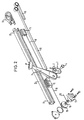
- the lower mounting bracket 1 comprises an anchor plate 2, which together with a support arm 3 by means of a bolt 4 is attached to a first sliding block 5.
- the anchor plate 2 has a receptacle 6 for the end remote from the roller of a seat belt and is in the fixed end 7 of the feed arm 3 fitted.
- the support arm 3 has one Carrying out 8 for the seat belt and is together with the anchor plate 2 relative to the sliding block 5 such arranged inclined that the guided through the implementation 8 Seat belt to the front of the associated vehicle seat is presented there.
- the sliding block 5 is c-shaped in cross section Rail 9 guided between two end positions, which is to the side of the associated vehicle seat in the direction of displacement it is attached to the vehicle.
- the usual passenger car is the rail 9, for example attached to the inside of the corresponding sill.
- On the sliding block 5 engages a spiral band spring 10 which with its other end in one at the front end 12 of the Rail 9 existing housing 11 is anchored and by this is included.
- the power of the sliding block 5 in Direction on the front end 12 of the rail 9 loading Spring 10 acts on the associated one, not shown here Vehicle seat attached driver opposite to the the sliding block 5 attacks on the front. At the front position this driver allows a displacement of the vehicle seat the sliding block 5 to its front end position, while the sliding block 5 in the rearmost sitting position in its rear end position at the rear end 13 takes the rail 9.
- a second slidably guided Sliding block 14 is provided, which continues in the rail 9 is arranged at the front as the first sliding block 5.
- the second Sliding block 14 is also by a second coil spring 15 loaded towards the front end 12 of the rail, which in turn has its other end in the housing 11 is anchored and taken up by this.
- a Bowden cable 16 In opposite Direction engages with the second sliding block 14 a Bowden cable 16, which is not shown here Backrest of the associated vehicle seat is operated.
- the first sliding block 5 is together with the lower mounting bracket 2 and the arm 3 for the seat belt through the associated vehicle seat Shifted depending on the seat position in the rail 9, so that the seat belt is relative to the vehicle seat always presented in the same comfortable gripping position becomes.
- the vehicle seat When the vehicle seat is moved back, it either works the driver or the one controlled by the vehicle seat Bowden cable against the force of the coil spring 10 on the Slide block 5 and moves it to the rear end 13 of the Rail 9 back.
- the sliding block 5 moves accordingly in the forward process of the associated vehicle seat far towards the front end 12 of the rail 9, such as the driver or the Bowden cable allow it. At the forefront The sliding block 5 is also in its sitting position foremost position.
- the second sliding block 14 is when the seat back is upright of the associated vehicle seat in its foremost Position at the front end 12 of the rail 9.
- the second sliding block 14 is thereby against the force of the spiral band spring 15 in the direction moved to the rear end 13 of the rail 9 until it on the first sliding block 5 hits.
- the second sliding block 14 takes the first sliding block 5 with it and moves together with this into the common rear End position at the rear end 13 of the rail 9.
- the through the implementation 8 of the arm 3 guided seat belt the access area becomes the associated one Vehicle door moved out, so that getting on a rear bench is relieved.
- the seat belt is in place practically in the same with the backrest folded down Position like a conventional seat belt system without sliding lower fastening fitting 2.
- FIGS. 3 and 4 show an enlarged view Section of the rail 9 according to the invention and in this arranged first sliding block 5.
- This is a variant of the embodiment shown in FIGS. 1 and 2, in which the sliding block 5 with an upward pointing latch 21 is provided.
- the cross section C-shaped rail 9 has corresponding 22 in its upper leg Snap-in recesses 23 into which the nose 21 of the first sliding block 5 can be snapped into place.
- the snapped Position is shown in Fig. 4.
Landscapes
- Engineering & Computer Science (AREA)
- Mechanical Engineering (AREA)
- Automotive Seat Belt Assembly (AREA)
- Seats For Vehicles (AREA)
Description
- Fig.1
- eine perspektivische Seitenansicht der Anordnung des unteren Befestigungsbeschlages,
- Fig. 2
- eine Explosionsdarstellung des Gegenstandes von Fig. 1,
- Fig. 3
- eine teilweise geschnittene Seitenansicht eines Abschnitts der Schiene von Fig. 1 mit unbelastetem Gleitstein in vergrößerter Darstellung, und
- Fig. 4
- den Gegenstand von Fig. 3 mit belastetem Gleitstein in gleicher Darstellung.
Claims (9)
- Sicherheitsgurtsystem für in Fahrzeuglängsrichtung verschiebbare Sitze eines Fahrzeugs mit einem von einer Rolle abwickelbaren Gurt (25), mit einem oberen Umlenk- oder Befestigungsbeschlag für den Gurt (25) und mit einem seitlich zum zugeordneten Sitz angeordneten unteren Befestigungsbeschlag (2) für das rollenfeme Ende des Gurtes (25), wobei der zugehörige Fahrzeugsitz eine zur Sitzfläche umklappbare Lehne aufweist und wobei der untere Befestigungsbeschlag (2) in Fahrzeuglängsrichtung derart verschiebbar am Fahrzeug befestigt ist,dadurch gekennzeichnet, dassdass seine Verschiebestellung über den zugeordneten Fahrzeugsitz in Abhängigkeit von dessen Längsstellung gesteuert ist unddass er beim Umklappen der Lehne des Sitzes automatisch in seine dem oberen Befestigungs- oder Umlenkbeschlag nähere Endstellung verschoben wird, und wobeider untere Befestigungsbeschlag (2) an einem Gleitstein (5) angebracht ist, welcher in einer Schiene (9) verschiebbar geführt ist,auf der dem oberen Befestigungs- oder Umlenkbeschlag abgewandten Seite des ersten Gleitsteins (5) in der Schiene (9) ein zweiter Gleitstein (14) vorhanden ist, welcher in Abhängigkeit von der Klappstellung der Lehne verschiebbar ist, wobei sich der zweite Gleitstein (14) bei aufgerichteter Lehne in der dem oberen Befestigungs- oder Umlenkbeschlag femen, und bei umgeklappter Lehne in der nahen Endstellung befindet.
- Sicherheitsgurtsystem nach Anspruch 1, dadurch gekennzeichnet, dass zur Verschiebung des zweiten Gleitsteins (14) ein über die Lehne betätigbarer Bowdenzug (16) vorgesehen ist.
- Sicherheitsgurtsystem nach Anspruch 1 oder 2, dadurch gekennzeichnet, dass der zweite Gleitstein (14) durch ein Federelement (15) in Richtung auf die dem oberen Befestigungs- oder Umlenkbeschlag feme Endstellung belastet ist.
- Sicherheitsgurtsystem nach einem der vorangehenden Ansprüche, dadurch gekennzeichnet, dass an dem unteren Befestigungsbeschlag (2) ein mit diesem verschiebbarer Vorlegearm (3) angelenkt ist, über welchen der Gurt (25) geführt ist und der insbesondere in Richtung auf die Vorderseite des zugeordneten Sitzes geneigt angeordnet ist.
- Sicherheitsgurtsystem nach Anspruch 4, dadurch gekennzeichnet, dass der Gleitstein (5) auf seiner Oberseite mit einer Rastnase (21) versehen ist, welche zum Eingriff in entsprechende, an der Schiene (9) vorgesehene Rastaufnahmen (23) ausgebildet ist.
- Sicherheitsgurtsystem nach Anspruch 5, dadurch gekennzeichnet, dass zwischen Gleitstein (5) und Schiene (9) ein Federelement (24) vorhanden ist, weiches den Gleitstein (5) in Richtung auf seine ausgerastete Stellung belastet.
- Sicherheitsgurtsystem nach einem der Ansprüche 4 bis 6, dadurch gekennzeichnet, dass der Gleitstein (5) über einen am Fahrzeugsitz vorhandenen Mitnehmer verschiebbar ist.
- Sicherheitsgurtsystem nach einem der Ansprüche 4 bis 6, dadurch gekennzeichnet, dass der Gleitstein (5) über einen durch den Fahrzeugsitz gesteuerten Bowdenzug verschiebbar ist.
- Sicherheitsgurtsystem nach Anspruch 7 oder 8, dadurch gekennzeichnet, dass der Gleitstein (5) durch ein Federelement (10) in Richtung auf seine eine Endstellung belastet ist.
Applications Claiming Priority (2)
| Application Number | Priority Date | Filing Date | Title |
|---|---|---|---|
| DE19615655 | 1996-04-19 | ||
| DE19615655A DE19615655A1 (de) | 1996-04-19 | 1996-04-19 | Sicherheitsgurtsystem |
Publications (3)
| Publication Number | Publication Date |
|---|---|
| EP0802095A2 EP0802095A2 (de) | 1997-10-22 |
| EP0802095A3 EP0802095A3 (de) | 2001-01-10 |
| EP0802095B1 true EP0802095B1 (de) | 2004-04-07 |
Family
ID=7791862
Family Applications (1)
| Application Number | Title | Priority Date | Filing Date |
|---|---|---|---|
| EP97106592A Expired - Lifetime EP0802095B1 (de) | 1996-04-19 | 1997-04-21 | Sicherheitsgurtsystem |
Country Status (3)
| Country | Link |
|---|---|
| US (1) | US5924772A (de) |
| EP (1) | EP0802095B1 (de) |
| DE (2) | DE19615655A1 (de) |
Cited By (1)
| Publication number | Priority date | Publication date | Assignee | Title |
|---|---|---|---|---|
| CN106476749A (zh) * | 2016-11-24 | 2017-03-08 | 中国民用航空总局第二研究所 | 一种新型安全带固定结构 |
Families Citing this family (10)
| Publication number | Priority date | Publication date | Assignee | Title |
|---|---|---|---|---|
| JP2000016241A (ja) * | 1998-06-30 | 2000-01-18 | Toyota Auto Body Co Ltd | 車両用シートにおける中央席用シートベルトの取付装置 |
| US6279954B1 (en) * | 1999-07-28 | 2001-08-28 | Joalto Design, Inc. | Restraint belt presenter having offset rotary action |
| FR2805228B1 (fr) * | 2000-02-21 | 2002-07-12 | Faure Bertrand Equipements Sa | Platine d'ancrage d'un organe d'accrochage d'une ceinture de securite de vehicule automobile |
| DE102005008189B4 (de) * | 2005-02-23 | 2007-09-06 | Daimlerchrysler Ag | Kraftfahrzeugsitz |
| DE102006043161A1 (de) * | 2006-09-14 | 2008-03-27 | Trw Automotive Gmbh | Baugruppe zur Mitnahme eines Gurtschlosses durch einen Fahrzeugsitz |
| WO2014205443A1 (en) * | 2013-06-21 | 2014-12-24 | Zodiac Seats Us Llc | Self-aligning safety belt |
| US11180110B2 (en) * | 2018-09-12 | 2021-11-23 | Ford Global Technologies, Llc | Vehicle buckle assembly |
| KR20250022436A (ko) * | 2023-08-08 | 2025-02-17 | 현대자동차주식회사 | 시트벨트 장치 및 그 장착방법 |
| US12358450B2 (en) | 2023-09-25 | 2025-07-15 | Ford Global Technologies, Llc | Rotatable seatbelt buckle |
| US12384323B2 (en) * | 2023-09-25 | 2025-08-12 | Ford Global Technologies, Llc | Rotatable seatbelt buckle |
Family Cites Families (20)
| Publication number | Priority date | Publication date | Assignee | Title |
|---|---|---|---|---|
| DE2014007B2 (de) * | 1970-03-24 | 1976-01-22 | Daimler-Benz Ag, 7000 Stuttgart | Befestigung eines sicherheitsgurtes an einem fahrzeugsitz |
| NL142119B (nl) * | 1971-11-08 | 1974-05-15 | Coenen Willem Frans | Veiligheidsgordel voor een motorvoertuig. |
| DE2802617C2 (de) * | 1978-01-21 | 1985-01-10 | Keiper Automobiltechnik Gmbh & Co Kg, 5630 Remscheid | Verankerung für Gurtschlösser |
| US4159848A (en) * | 1978-06-12 | 1979-07-03 | General Motors Corporation | Linear locking seat belt retractor |
| DE2826634A1 (de) * | 1978-06-19 | 1980-01-03 | Daimler Benz Ag | An einem festen fahrzeugteil sich abstuetzende rastschiene |
| JPS5581445U (de) * | 1978-12-01 | 1980-06-05 | ||
| US4258933A (en) * | 1978-12-25 | 1981-03-31 | Juichiro Takada | Movable inboard belt guide for use in passive vehicle occupant restraint systems |
| DE3241836C2 (de) * | 1982-11-12 | 1986-02-27 | Daimler-Benz Ag, 7000 Stuttgart | Einem Kraftfahrzeugsitz zugeordnetes Gurtschloß |
| DE3514769A1 (de) * | 1984-05-03 | 1985-11-07 | Volkswagenwerk Ag, 3180 Wolfsburg | Sicherheitsgurtanordnung |
| DE3539051A1 (de) * | 1984-11-06 | 1986-05-15 | Volkswagen AG, 3180 Wolfsburg | Sicherheitsgurtanordnung |
| GB2182839B (en) * | 1985-11-14 | 1989-10-04 | Autoliv Dev | Improvements in or relating to a safety belt system |
| DE3743012A1 (de) * | 1987-01-07 | 1988-07-21 | Volkswagen Ag | Sicherheitseinrichtung |
| JPH0260655U (de) * | 1988-10-28 | 1990-05-07 | ||
| US4923214A (en) * | 1989-01-26 | 1990-05-08 | Hoover Universal, Inc. | Seat belt anchorage |
| DE3938416A1 (de) * | 1989-11-18 | 1991-05-23 | Daimler Benz Ag | Vorrichtung zur selbsttaetigen anpassung der hoehenlage des oberen befestigungs-bzw. umlenkpunktes |
| US5031961A (en) * | 1989-11-29 | 1991-07-16 | Ford Motor Company | Seat belt mounting assembly |
| GB2242608B (en) * | 1990-02-27 | 1993-11-10 | Gen Engineering | Improvements in or relating to a safety belt arrangement |
| US5226697A (en) * | 1990-08-10 | 1993-07-13 | General Motors Corporation | Seat belt anchor for vehicle seat |
| JPH0798470B2 (ja) * | 1990-08-30 | 1995-10-25 | 株式会社東海理化電機製作所 | オートマチツクシートベルト装置 |
| US5294184A (en) * | 1992-06-24 | 1994-03-15 | General Motors Corporation | Omni locking adjustable seat belt load transfer mechanism |
-
1996
- 1996-04-19 DE DE19615655A patent/DE19615655A1/de not_active Ceased
-
1997
- 1997-04-21 US US08/845,153 patent/US5924772A/en not_active Expired - Fee Related
- 1997-04-21 DE DE59711486T patent/DE59711486D1/de not_active Expired - Fee Related
- 1997-04-21 EP EP97106592A patent/EP0802095B1/de not_active Expired - Lifetime
Cited By (2)
| Publication number | Priority date | Publication date | Assignee | Title |
|---|---|---|---|---|
| CN106476749A (zh) * | 2016-11-24 | 2017-03-08 | 中国民用航空总局第二研究所 | 一种新型安全带固定结构 |
| CN106476749B (zh) * | 2016-11-24 | 2019-04-30 | 中国民用航空总局第二研究所 | 一种新型安全带固定结构 |
Also Published As
| Publication number | Publication date |
|---|---|
| EP0802095A2 (de) | 1997-10-22 |
| US5924772A (en) | 1999-07-20 |
| DE19615655A1 (de) | 1997-10-23 |
| DE59711486D1 (de) | 2004-05-13 |
| EP0802095A3 (de) | 2001-01-10 |
Similar Documents
| Publication | Publication Date | Title |
|---|---|---|
| EP2655125B1 (de) | Längseinstellbarer fahrzeugsitz | |
| EP1034974B1 (de) | Fahrzeugsitz | |
| DE10246834B4 (de) | Sitzverriegelungsanordnung | |
| DE3302356A1 (de) | Zufuehrvorrichtung fuer ein sicherheitsgurtsystem fuer kraftfahrzeuge | |
| DE19744978C2 (de) | Adapter | |
| EP2708407B1 (de) | Kindersitz, insbesondere Kindersicherheitssitz für Fahrzeuge | |
| DE202005013453U1 (de) | Kinderschutzsystem für Kraftfahrzeuge | |
| DE2145022C2 (de) | Sicherheitsgurtsystem für ein Kraftfahrzeug | |
| EP0802095B1 (de) | Sicherheitsgurtsystem | |
| DE2206631A1 (de) | Automatische Anlegevorrichtung für Sicherheitsgurte | |
| EP1392545B1 (de) | Kraftfahrzeugsitz | |
| DE69628941T2 (de) | Anordnung für sicherheitsgurt | |
| EP1838561A1 (de) | Höhenverstellbare umlenkvorrichtung für einen dreipunktgurt, fahrzeugsitz mit einem dreipunktgurt sowie verfahren zur höhenverstellung des oberen haltepunktes eines dreipunktgurtes | |
| DE19629964A1 (de) | Kraftfahrzeugsitz | |
| DE3002500A1 (de) | Vorrichtung zur verstellung der lage eines versetzbaren elements bei einem fahrzeug, beispielsweise des fahrzeugsitzes | |
| DE19532530C1 (de) | Rücksitzanlage für ein Kraftfahrzeug, insbesondere Personenkraftwagen | |
| DE3616452A1 (de) | Einrichtung zum verstellen eines langgestreckten gliedes | |
| DE2622556A1 (de) | Fahrzeug, insbesondere kraftfahrzeug, mit im wesentlichen horizontal verstellbaren sitzen | |
| EP1057696B1 (de) | Überroll-Schutzsystem für Kraftfahrzeuge | |
| DE19528308C2 (de) | Fahrzeug, insbesondere Personenkraftwagen | |
| DE19602021C1 (de) | Vorrichtung zur Lagerung einer höhenverstellbaren Gurtumlenköse für Kraftfahrzeuge | |
| DE10052829A1 (de) | Vorrichtung zur Arretierung eines beweglichen Körpers, insbesondere in einem Kfz | |
| DE102005009182A1 (de) | Kraftfahrzeug | |
| EP1332066B1 (de) | Gelenkhebelkonstruktion für ein sitzgestell | |
| DE102005026072B4 (de) | Fahrzeugsitz mit schwenkbarer Lehne |
Legal Events
| Date | Code | Title | Description |
|---|---|---|---|
| PUAI | Public reference made under article 153(3) epc to a published international application that has entered the european phase |
Free format text: ORIGINAL CODE: 0009012 |
|
| AK | Designated contracting states |
Kind code of ref document: A2 Designated state(s): DE GB |
|
| PUAL | Search report despatched |
Free format text: ORIGINAL CODE: 0009013 |
|
| AK | Designated contracting states |
Kind code of ref document: A3 Designated state(s): DE GB |
|
| RIC1 | Information provided on ipc code assigned before grant |
Free format text: 7B 60R 22/20 A, 7B 60R 22/22 B |
|
| 17P | Request for examination filed |
Effective date: 20010710 |
|
| RAP1 | Party data changed (applicant data changed or rights of an application transferred) |
Owner name: TAKATA-PETRI (ULM) GMBH |
|
| 17Q | First examination report despatched |
Effective date: 20021021 |
|
| GRAP | Despatch of communication of intention to grant a patent |
Free format text: ORIGINAL CODE: EPIDOSNIGR1 |
|
| GRAS | Grant fee paid |
Free format text: ORIGINAL CODE: EPIDOSNIGR3 |
|
| GRAA | (expected) grant |
Free format text: ORIGINAL CODE: 0009210 |
|
| AK | Designated contracting states |
Kind code of ref document: B1 Designated state(s): DE GB |
|
| REG | Reference to a national code |
Ref country code: GB Ref legal event code: FG4D Free format text: NOT ENGLISH |
|
| REF | Corresponds to: |
Ref document number: 59711486 Country of ref document: DE Date of ref document: 20040513 Kind code of ref document: P |
|
| GBT | Gb: translation of ep patent filed (gb section 77(6)(a)/1977) |
Effective date: 20040625 |
|
| PLBE | No opposition filed within time limit |
Free format text: ORIGINAL CODE: 0009261 |
|
| STAA | Information on the status of an ep patent application or granted ep patent |
Free format text: STATUS: NO OPPOSITION FILED WITHIN TIME LIMIT |
|
| 26N | No opposition filed |
Effective date: 20050110 |
|
| PGFP | Annual fee paid to national office [announced via postgrant information from national office to epo] |
Ref country code: DE Payment date: 20060413 Year of fee payment: 10 |
|
| PGFP | Annual fee paid to national office [announced via postgrant information from national office to epo] |
Ref country code: GB Payment date: 20060419 Year of fee payment: 10 |
|
| GBPC | Gb: european patent ceased through non-payment of renewal fee |
Effective date: 20070421 |
|
| PG25 | Lapsed in a contracting state [announced via postgrant information from national office to epo] |
Ref country code: DE Free format text: LAPSE BECAUSE OF NON-PAYMENT OF DUE FEES Effective date: 20071101 |
|
| PG25 | Lapsed in a contracting state [announced via postgrant information from national office to epo] |
Ref country code: GB Free format text: LAPSE BECAUSE OF NON-PAYMENT OF DUE FEES Effective date: 20070421 |