EP0802095B1 - Safety belt system - Google Patents
Safety belt system Download PDFInfo
- Publication number
- EP0802095B1 EP0802095B1 EP97106592A EP97106592A EP0802095B1 EP 0802095 B1 EP0802095 B1 EP 0802095B1 EP 97106592 A EP97106592 A EP 97106592A EP 97106592 A EP97106592 A EP 97106592A EP 0802095 B1 EP0802095 B1 EP 0802095B1
- Authority
- EP
- European Patent Office
- Prior art keywords
- sliding block
- seat
- seat belt
- vehicle
- fitting
- Prior art date
- Legal status (The legal status is an assumption and is not a legal conclusion. Google has not performed a legal analysis and makes no representation as to the accuracy of the status listed.)
- Expired - Lifetime
Links
Images


Classifications
-
- B—PERFORMING OPERATIONS; TRANSPORTING
- B60—VEHICLES IN GENERAL
- B60R—VEHICLES, VEHICLE FITTINGS, OR VEHICLE PARTS, NOT OTHERWISE PROVIDED FOR
- B60R22/00—Safety belts or body harnesses in vehicles
- B60R22/18—Anchoring devices
- B60R22/20—Anchoring devices adjustable in position, e.g. in height
-
- B—PERFORMING OPERATIONS; TRANSPORTING
- B60—VEHICLES IN GENERAL
- B60R—VEHICLES, VEHICLE FITTINGS, OR VEHICLE PARTS, NOT OTHERWISE PROVIDED FOR
- B60R22/00—Safety belts or body harnesses in vehicles
- B60R22/18—Anchoring devices
- B60R22/26—Anchoring devices secured to the seat
-
- B—PERFORMING OPERATIONS; TRANSPORTING
- B60—VEHICLES IN GENERAL
- B60R—VEHICLES, VEHICLE FITTINGS, OR VEHICLE PARTS, NOT OTHERWISE PROVIDED FOR
- B60R22/00—Safety belts or body harnesses in vehicles
- B60R22/18—Anchoring devices
- B60R22/20—Anchoring devices adjustable in position, e.g. in height
- B60R2022/207—Horizontally or transversally adjustable
-
- B—PERFORMING OPERATIONS; TRANSPORTING
- B60—VEHICLES IN GENERAL
- B60R—VEHICLES, VEHICLE FITTINGS, OR VEHICLE PARTS, NOT OTHERWISE PROVIDED FOR
- B60R22/00—Safety belts or body harnesses in vehicles
- B60R22/18—Anchoring devices
- B60R22/20—Anchoring devices adjustable in position, e.g. in height
- B60R2022/208—Anchoring devices adjustable in position, e.g. in height by automatic or remote control means
-
- B—PERFORMING OPERATIONS; TRANSPORTING
- B60—VEHICLES IN GENERAL
- B60R—VEHICLES, VEHICLE FITTINGS, OR VEHICLE PARTS, NOT OTHERWISE PROVIDED FOR
- B60R22/00—Safety belts or body harnesses in vehicles
- B60R22/18—Anchoring devices
- B60R22/20—Anchoring devices adjustable in position, e.g. in height
- B60R22/201—Anchoring devices adjustable in position, e.g. in height with the belt anchor connected to a slider movable in a vehicle-mounted track
- B60R22/205—Anchoring devices adjustable in position, e.g. in height with the belt anchor connected to a slider movable in a vehicle-mounted track the slider comprising emergency actuated locking means
Description
Die Erfindung betrifft ein Sicherheitsgurtsystem mit den Merkmalen gemäß dem Oberbegriff des Anspruchs 1.The invention relates to a seat belt system with the features according to the Preamble of claim 1.
Insbesondere bei zweitürigen Personenkraftwagen ist der Sicherheitsgurt in bezug auf den zugehörigen Fahrzeugsitz relativ weit hinten am Kraftfahrzeug angeschlagen. Das Ergreifen des Sicherheitsgutes zum Anlegen desselben ist entsprechend umständlich, da eine starke Körperdrehung erforderlich ist. Dieses Problem wird verschärft, je weiter der zugeordnete Sitz nach vorne vorgeschoben ist.In the case of two-door passenger cars in particular, the seat belt is related to the associated vehicle seat struck relatively far behind on the motor vehicle. The Grasping the security goods to put on the same is correspondingly cumbersome because a strong body rotation is required. This problem is exacerbated the further the assigned seat is pushed forward.
Es sind daher bereits Vorrichtungen bekannt, die den nicht angelegten Sicherheitsgurt erfassen und in eine bequemere Greifposition zu dem Fahrzeugsitz bewegen. Diese bekannten Vorrichtungen arbeiten mit einem elektromotorisch angetriebenen Greifarm, welcher bei Benutzung des Fahrzeugsitzes automatisch in Aktion tritt. Diese Lösung ist verhältnismäßig aufwendig und daher kostenintensiv und störanfällig.Devices are therefore already known that the seat belt not fastened capture and move to a more comfortable gripping position to the vehicle seat. This known devices work with an electromotive driven gripper arm, which automatically comes into action when the vehicle seat is used. This solution is relatively complex and therefore costly and prone to failure.
Aus der DE-PS 35 14 769 C2 ist ein Sicherheitsgurtsystem mit einem unteren Befestigungsbeschlag für den Sicherheitsgurt bekannt, weicher in Fahrzeuglängsrichtung verschiebbar am Fahrzeug befestigt ist. Die Verschiebung erfolgt dabei manuell durch den Benutzer des Fahrzeugsitzes nach dem Anlegen des Sicherheitsgurtes und hat den Zweck, die Anordnung des unteren Befestigungsbeschlages relativ zum Fahrzeug in Abhängigkeit von der Sitzstellung und dem Körperbau des Sitzbenutzers einzustellen. Ein erleichtertes Ergreifen des Sicherheitsgurtes ist mit dieser Anordnung weder bezweckt noch ausreichend sichergestellt, da die Verschiebung des unteren Befestigungsbeschlages erst nach dem Anlegen des Sicherheitsgurtes erfolgt. Der untere Befestigungsbeschlag befindet sich daher vor dem Anlegen in einer Position, die durch den vorherigen Benutzer des Fahrzeugsitzes bestimmt wurde und folglich an die gegenwärtige Benutzung nicht angepasst ist. From DE-PS 35 14 769 C2 is a seat belt system with a lower Fastening fitting for the seat belt known, softer in the vehicle's longitudinal direction is slidably attached to the vehicle. The shift is done manually the user of the vehicle seat after wearing the seat belt and has the Purpose, the arrangement of the lower mounting bracket relative to the vehicle in Depending on the seating position and the physique of the seat user. With this arrangement, it is neither easier to grip the seat belt Purpose is still sufficiently ensured, since the shift of the lower Fastening only after the seat belt has been fastened. The The lower fastening fitting is therefore in a position before being put on was determined by the previous user of the vehicle seat and consequently to the current use is not adapted.
In der deutschen Offenlegungsschrift DE 35 39 051 A1 ist einer gattungsgemäße Sicherheitsgurtanordnung beschrieben, bei der das untere rollenferne Ende des Sicherheitsgurtes in Fahrzeuglängsrichtung verschiebbar befestigt ist. Um eine optimale Lage des Sicherheitsgurtes am Körper des Fahrzeuginsassen, insbesondere in dessen Beckenbereich, zu erreichen, weist die Sicherheitsgurtanordnung eine Vorrichtung zur Begrenzung einer in Fahrtrichtung nach vom gerichteten Verstellung des Gurt-Endes auf. Darüber hinaus weist die Sicherheitsgurtanordnung Mittel auf, mit denen das Gurt-Ende in eine den Einstieg in das Fahrzeug nicht behindernde Ablageposition zurückgeführt wird. Diese Mittel sind beispielsweise durch eine an dem Gurt-Ende angreifende Feder gebildet.In the German patent application DE 35 39 051 A1 there is a generic seat belt arrangement described in which the lower end of the seat belt remote from the roller in Vehicle longitudinal direction is slidably attached. To an optimal location of the Seat belt on the body of the vehicle occupant, especially in the vehicle To reach the pelvic area, the seat belt arrangement has a device for Limitation in the direction of travel from the directed adjustment of the belt end on. In addition, the seat belt arrangement has means with which the belt end in a storage position that does not impede entry into the vehicle is returned. These means are, for example, by one at the end of the belt attacking spring formed.
Aus der deutschen Offenlegungsschrift 28 02 617 ist ein Gurtschloss bekannt, das längsverstellbar am Fahrzeugboden befestigt ist. Das Gurtschloss steht dabei derart mit dem Fahrzeugsitz in Verbindung, dass das Gurtschloss bei einem Verschieben des Fahrzeugsitzes mitgeführt wird, so dass das Gurtschloss stets die optimale Position relativ zum Fahrzeugsitz aufweist.From the German patent application 28 02 617 a belt buckle is known that is longitudinally adjustable attached to the vehicle floor. The buckle stands with it the vehicle seat in connection that the belt buckle when the Vehicle seat is carried so that the belt buckle is always in the optimal position has relative to the vehicle seat.
Ein Sicherheitsgurtsystem mit den Merkmalen gemäß dem Oberbegriff des Anspruch 1
ist aus der britischen Patentanmeldung GB 22 42 608 bekannt. Bei diesem
Sicherheitsgurtsystem ist der untere Befestigungsbeschlag an einer Führungsstange
gleitend befestigt. Bei aufrechter Sitzlehne gleitet der untere Befestigungsbeschlag in
Richtung nach vom und schlägt an einem Anschlag an, der am Sitz befestigt ist und
dessen Position somit von der Sitzstellung abhängt. Bei umgeklappter Sitzlehne gleitet
der untere Befestigungsbeschlag in seine dem oberen Befestigungsbeschlag nähere
Endsteliung.A seat belt system with the features according to the preamble of claim 1
is known from British
Der Erfindung liegt die Aufgabe zugrunde, ein Sicherheitsgurtsystem der eingangs genannten Art so weiterzubilden, dass der Sicherheitsgurt stets in eine bequeme Greifposition gebracht wird, bevor der Sicherheitsgurt angelegt wird. Darüber hinaus soll bei einem Umklappen der Sitzlehne in die hintere Endstellung ― beispielsweise bei einem zweisitzigen Fahrzeug - der Durchstieg auf die hintere Sitzbank freigegeben werden.The invention has for its object a seat belt system of the beginning mentioned type so that the seat belt is always in a comfortable Gripping position is brought before the seat belt is fastened. Beyond that when the seat back is folded into the rear end position - for example in one two-seat vehicle - the step on the rear seat can be released.
Diese Aufgabe wird bei einem Sicherheitsgurtsystem gemäß dem Oberbegriff des Anspruchs 1 erfindungsgemäß durch die kennzeichnenden Merkmale des Anspruchs 1 gelöst. This task is in a seat belt system according to the preamble of Claim 1 according to the invention by the characterizing features of claim 1 solved.
Durch die Steuerung der Verschiebestellung des unteren Befestigungsbeschlages in Abhängigkeit von der Längsstellung des zugeordneten Fahrzeugsitzes ist gewährleistet, dass sich der untere Befestigungsbeschlag mit dem Fahrzeugsitz bewegt, sich also stets in der gleichen Stellung zum Fahrzeugsitz befindet. Das Ergreifen des Sicherheitsgurtes ist daher in jeder Sitzstellung gleich gut möglich, so dass der Sicherheitsgurt also auch in vorderster Stellung des Fahrzeugsitzes leicht ergriffen werden kann. Durch die Steuerung der Verschiebestellung durch den zugeordneten Fahrzeugsitz selbst ergibt sich der Vorteil, dass der Sicherheitsgurt bereits vor dem Anlegen beim Verstellen des Fahrzeugsitzes in eine bequeme Greifposition mitgenommen wird.By controlling the sliding position of the lower mounting bracket in Dependence on the longitudinal position of the assigned vehicle seat is ensured that the lower mounting bracket moves with the vehicle seat, i.e. always is in the same position to the vehicle seat. Grasping the seat belt is therefore equally possible in every sitting position, so that the seat belt also in the front position of the vehicle seat can be easily gripped. Through the Control of the displacement position by the assigned vehicle seat itself results the advantage that the seat belt before putting on when adjusting the Vehicle seat is taken into a comfortable gripping position.
Durch das Verschieben des unteren Befestigungsbeschlages beim Umklappen der Lehne in die hintere Endstellung wird außerdem der Durchstieg auf die hintere Sitzbank - beispielsweise bei einem zweisitzigen Fahrzeug - freigegeben. Das heißt, der Sicherheitsgurt befindet sich bei umgeklappter Sitzlehne im wesentlichen derselben Position wie bei einem herkömmlichen Sicherheitsgurtsystem ohne verschiebbaren unteren Befestigungsbeschlag. Beim Aufrichten der Lehne wird der untere Befestigungsbeschlag dann wieder in seine der Sitzstellung des zugeordneten Fahrzeugsitzes entsprechende Stellung in der Schiene zurückverschoben, so dass der Gurt wieder in einer bequemen Greifhaltung präsentiert wird.By moving the lower mounting bracket when folding the Lean into the rear end position and the step onto the rear seat - For example, in a two-seat vehicle - released. That is, the Seat belt is essentially the same when the seat back is folded down Position like a conventional seat belt system with no sliding lower mounting bracket. When the backrest is raised, the lower one Fastening fitting then back into its assigned seating position Vehicle seat corresponding position in the rail moved back so that the Belt is presented again in a comfortable gripping position.
Bei der Erfindung ist der untere Befestigungsbeschlag an einem Gleitstein angebracht, welcher in einer Schiene verschiebbar geführt ist. Hierdurch ist eine sichere Verschiebung des Befestigungsbeschlages und dennoch eine ausreichend feste Verankerung desselben am Fahrzeug gewährleistet.In the invention, the lower fastening fitting is attached to a sliding block, which is slidably guided in a rail. This is a safe one Displacement of the mounting bracket and still a sufficiently firm Anchoring the same guaranteed to the vehicle.
Zur Verschiebung des unteren Befestigungsbeschlages in seine den Durchstieg freigebende Endstellung ist auf der dem oberen Befestigungs- oder Umlenkbeschlag abgewandten Seite des ersten Gleitsteins ein zweiter Gleitstein vorhanden, welcher in Abhängigkeit von der Klappstellung der Lehne verschiebbar ist. Die automatische Verschiebung des zweiten Gleitsteins ist so vorgesehen, dass sich dieser bei aufgerichteter Lehne in der dem oberen Befestigungs- oder Umlenkbeschlag femen und bei umgeklappter Lehne in seiner diesem nahen Endstellung befindet. Bei aufgerichteter Lehne kann sich daher der erste Gleitstein in seine durch die Sitzstellung des zugeordneten Fahrzeugsitzes festgelegte Position bewegen, während er beim Umklappen der Lehne durch den durch die Lehne nach hinten bewegten zweiten Gleitstein mitgenommen und zusammen mit diesem in die den Durchstieg freigebende Endstellung verschoben wird.To move the lower fastening fitting into its access releasing end position is on the upper fastening or deflection fitting facing away from the first sliding block, a second sliding block is available, which in Depending on the folding position of the backrest is displaceable. The automatic Movement of the second sliding block is provided so that it is at erect the backrest in the upper fastening or deflection fitting and when the backrest is folded in its near end position. With erect The first sliding block can therefore lean back into its seat position assigned vehicle seat move position while he at Folding the backrest down by the second one moved backwards through the backrest Take the sliding block and together with it into the one that clears the passage End position is shifted.
Die Verschiebung des zweiten Gleitsteins kann über einen durch die Lehne betätigbaren Bowdenzug erfolgen. Der Gleitstein ist dabei bevorzugt durch ein Federelement in Richtung auf die dem oberen Befestigungs- oder Umlenkbeschlag feme Endstellung belastet. Durch diese Ausgestaltung ist sichergestellt, dass der den unteren Umlenkbeschlag in seine den Durchstieg freigebende Entstellung verschiebende Bowdenzug stets gespannt ist.The displacement of the second sliding block can be actuated by means of the backrest Bowden cable take place. The sliding block is preferably by a spring element in Direction to the end position remote from the upper fastening or deflection fitting loaded. This configuration ensures that the lower Deflecting fitting in its displacement releasing the passage Bowden cable is always excited.
Durch einen an dem unteren Befestigungsbeschlag angelenkten und daher mit diesem beweglichen Vorlegearm, über den der Gurt geführt ist, wird der Gurt in einer noch bequemeren Greifstellung vorgehalten. Hierfür ist der Vorlegearm insbesondere zur Vorderseite des zugehörigen Sitzes hin geneigt angeordnet. Zum Ergreifen des derart stets in der gleichen Vorlageposition zum Fahrzeugsitz gehaltenen Sicherheitsgurts ist daher, wenn überhaupt, nur eine geringe Körperdrehung erforderlich.By a hinged to the lower mounting bracket and therefore with this movable feed arm over which the belt is guided, the belt is still in one more comfortable gripping position. The support arm is especially for this Front of the associated seat arranged inclined. To grasp the like is always in the same position as the seat belt held to the vehicle seat therefore, if any, only a small amount of body rotation is required.
Zur zusätzlichen Festlegung des Gleitsteins in der Schiene für den Fall einer Belastung des Sicherheitsgurtes, wie sie insbesondere bei einem Unfall auftritt, ist der Gleitstein an seiner Oberseite mit einer Rastnase versehen, welche zum Eingriff in entsprechende, an der Schiene vorgesehene Rastaufnahmen ausgebildet ist. Hierdurch wird eine sichere und besonders stabile Blockierung des unteren Befestigungsbeschlages im Falle eines Unfalls bewirkt. Um eine problemlose Verschiebung des Gleitsteins in der Schiene bei unbelastetem Gurt sicherzustellen, kann darüber hinaus zwischen Gleitstein und Schiene ein Federelement vorgesehen sein, welches den Gleitstein in seine ausgerastete Stellung belastet.For additional fixing of the sliding block in the rail in the event of a load the seat belt, as occurs in particular in an accident, the sliding block is on its top with a locking lug, which for engagement in the corresponding the rail provided locking receptacles is formed. This will make it a safe one and particularly stable blocking of the lower mounting bracket in the event of a Accident causes. In order to easily move the sliding block in the rail To ensure that the belt is not under load, there can also be between the sliding block and the rail a spring element can be provided, which disengages the sliding block Position charged.
Die Verschiebung des Gleitsteins in der Schiene kann beispielsweise über einen am Fahrzeugsitz vorhandenen Mitnehmer oder über einen durch den Fahrzeugsitz gesteuerten Bowdenzug erfolgen. In beiden Fällen kann der Gleitstein durch ein Federelement in Richtung auf seine eine Endstellung belastet sein. Bei Verwendung eines Bowdenzuges ist dadurch eine stete Spannung des Zugseiles gewährleistet. Bei Verwendung eines Mitnehmers kann dieser so angeordnet sein, dass er im Gleitstein nur in der der Federkraft entgegengesetzten Richtung angreift, so dass eine Verschiebung des Gleitsteins entgegen der Federkraft vom Mitnehmer nicht blockiert wird. The displacement of the sliding block in the rail can be, for example, via a Vehicle seat existing driver or through a through the vehicle seat controlled Bowden cable. In both cases, the sliding block can be replaced by a Spring element to be loaded towards its one end position. Using a Bowden cable ensures a constant tension of the cable. at Using a driver, this can be arranged so that it is only in the sliding block attacks in the opposite direction of the spring force, causing a displacement the sliding block is not blocked by the driver against the spring force.
Ein Ausführungsbeispiel der Erfindung ist in der Zeichnung dargestellt und wird nachfolgend beschrieben. Es zeigen jeweils in schematischer Darstellung:
- Fig.1
- eine perspektivische Seitenansicht der Anordnung des unteren Befestigungsbeschlages,
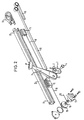
- Fig. 2
- eine Explosionsdarstellung des Gegenstandes von Fig. 1,
- Fig. 3
- eine teilweise geschnittene Seitenansicht eines Abschnitts der Schiene von Fig. 1 mit unbelastetem Gleitstein in vergrößerter Darstellung, und
- Fig. 4
- den Gegenstand von Fig. 3 mit belastetem Gleitstein in gleicher Darstellung.
- Fig.1
- a perspective side view of the arrangement of the lower mounting bracket,
- Fig. 2
- 2 shows an exploded view of the object from FIG. 1,
- Fig. 3
- a partially sectioned side view of a portion of the rail of FIG. 1 with an unloaded sliding block in an enlarged view, and
- Fig. 4
- 3 with loaded sliding block in the same representation.
Die Fig. 1 und 2 zeigen die Anordnung des unteren Befestigungsbeschlages
1 eines erfindungsgemäßen Sicherheitsgurtsystems
ohne Darstellung des Sicherheitsgurtes selbst. Der
untere Befestigungsbeschlag 1 umfaßt eine Ankerplatte 2,
welche zusammen mit einem Vorlegearm 3 mittels eines Bolzens
4 an einem ersten Gleitstein 5 befestigt ist. Die Ankerplatte
2 weist eine Aufnahme 6 für das rollenferne Ende
eines Sicherheitsgurtes auf und ist in das festgelegte Ende
7 des Vorlegearms 3 eingepaßt. Der Vorlegearm 3 weist eine
Durchführung 8 für den Sicherheitsgurt auf und ist zusammen
mit der Ankerplatte 2 gegenüber dem Gleitstein 5 derart
geneigt angeordnet, daß der durch die Durchführung 8 geführte
Sicherheitsgurt zur Vorderseite des zugehörigen Fahrzeugsitzes
hin präsentiert wird.1 and 2 show the arrangement of the lower mounting bracket
1 of a seat belt system according to the invention
without showing the seat belt itself. The
lower mounting bracket 1 comprises an anchor plate 2,
which together with a support arm 3 by means of a bolt
4 is attached to a first sliding
Der Gleitstein 5 ist in einer im Querschnitt c-förmigen
Schiene 9 zwischen zwei Endstellungen verschiebbar geführt,
welche seitlich zum zugehörigen Fahrzeugsitz in Verschieberichtung
desselben am Fahrzeug angebracht ist. Bei einem
üblichen Personenwagen ist die Schiene 9 beispielsweise an
der Innenseite des entsprechenden Schwellers befestigt. An
dem Gleitstein 5 greift eine Spiralbandfeder 10 an, welche
mit ihrem anderen Ende in einem an dem vorderen Ende 12 der
Schiene 9 vorhandenen Gehäuse 11 verankert ist und von
diesem aufgenommen wird. Der Kraft der den Gleitstein 5 in
Richtung auf das vordere Ende 12 der Schiene 9 belastenden
Feder 10 wirkt ein hier nicht dargestellter, an dem zugehörigen
Fahrzeugsitz angebrachter Mitnehmer entgegen, der an
dem Gleitstein 5 vorderseitig angreift. Bei vorderster Stellung
des Fahrzeugsitzes erlaubt dieser Mitnehmer eine Verschiebung
des Gleitsteins 5 bis in seine vordere Endstellung,
während er den Gleitstein 5 in der hintersten Sitzstellung
in seine hintere Endstellung am hinteren Ende 13
der Schiene 9 mitnimmt.The sliding
In der Schiene 9 ist ein zweiter verschiebbar geführter
Gleitstein 14 vorgesehen, welcher in der Schiene 9 weiter
vorne angeordnet ist als der erste Gleitstein 5. Der zweite
Gleitstein 14 ist durch eine zweite Spiralbandfeder 15 ebenfalls
in Richtung auf das vordere Ende 12 der Schiene belastet,
welche mit ihrem anderen Ende wiederum in dem Gehäuse
11 verankert ist und von diesem aufgenommen wird. In entgegengesetzter
Richtung greift an dem zweiten Gleitstein 14
ein Bowdenzug 16 an, welcher über die hier nicht dargestellte
Lehne des zugehörigen Fahrzeugsitzes betätigt wird. Um
den unterschiedlichen Weglängen der Fahrzeuglehne und des
zweiten Gleitsteins 14 Rechnung zu tragen, ist eine Übersetzungseinrichtung
17 mit zwei kraftschlüssig miteinander
verbundenen Rollen 18 und 19 unterschiedlichen Durchmessers
vorgesehen, auf die einerseits der Bowdenzug 16 und andererseits
ein zweiter Bowdenzug 20 aufwickelbar ist, der mit
seinem anderen Ende an der Lehne des zugeordneten Fährzeugsitzes
festgelegt ist.In the
Anstelle des am Fahrzeugsitz angeordneten Mitnehmers kann
zur Verschiebung des ersten Gleitsteins 5 auch ein weiterer
Bowdenzug vorgesehen sein, welcher an dem ersten Gleitstein
5 entgegen der Kraft der ersten Spiralbandfeder 10 angreift,
wobei auch hier eine Übersetzungseinrichtung vorgesehen sein
kann.Instead of the driver arranged on the vehicle seat
another for moving the first sliding
In beiden Fällen wird der erste Gleitstein 5 zusammen mit
dem unteren Befestigungsbeschlag 2 und dem Vorlegearm 3 für
den Sicherheitsgurt durch den zugehörigen Fahrzeugsitz in
Abhängigkeit von dessen Sitzstellung in der Schiene 9 verschoben,
so daß der Sicherheitsgurt relativ zum Fahrzeugsitz
stets in der gleichen bequemen Greifhaltung präsentiert
wird. Beim Zurückfahren des Fahrzeugsitzes wirkt dabei entweder
der Mitnehmer oder der vom Fahrzeugsitz gesteuerte
Bowdenzug entgegen der Kraft der Spiralbandfeder 10 auf den
Gleitstein 5 und verschiebt diesen zum hinteren Ende 13 der
Schiene 9 hin. Entsprechend bewegt sich der Gleitstein 5
beim Nachvorneverfahren des zugehörigen Fahrzeugsitzes so
weit in Richtung auf das vordere Ende 12 der Schiene 9, wie
es der Mitnehmer oder der Bowdenzug zulassen. Bei vorderster
Sitzstellung befindet sich auch der Gleitstein 5 in seiner
vordersten Stellung.In both cases, the first sliding
Der zweite Gleitstein 14 befindet sich bei aufrechter Sitzlehne
des zugehörigen Fahrzeugsitzes in seiner vordersten
Position am vorderen Ende 12 der Schiene 9. Durch Umklappen
der Lehne wird der Bowdenzug 16 über die Übersetzungseinrichtung
17 vom Bowdenzug 20 betätigt, der seinerseits von
der Lehne betätigt wird. Der zweite Gleitstein 14 wird dadurch
entgegen der Kraft der Spiralbandfeder 15 in Richtung
auf das hintere Ende 13 der Schiene 9 bewegt, bis er auf den
ersten Gleitstein 5 trifft. Beim Weiterumklappen der Lehne
nimmt der zweite Gleitstein 14 den ersten Gleitstein 5 mit
und bewegt sich zusammen mit diesem in die gemeinsame hintere
Endstellung am hinteren Ende 13 der Schiene 9. Der durch
die Durchführung 8 des Vorlegearms 3 geführte Sicherheitsgurt
wird dadurch aus dem Durchstiegsbereich der zugehörigen
Fahrzeugtüre herausbewegt, so daß ein Einsteigen auf eine
hintere Sitzbänk erleichtert ist. Der Sicherheitsgurt befindet
sich bei umgeklappter Lehne dadurch praktisch in derselben
Position wie bei einem herkömmlichen Sicherheitsgurtsystem
ohne verschiebbaren unteren Befestigungsbeschlag 2.The second sliding block 14 is when the seat back is upright
of the associated vehicle seat in its foremost
Position at the
Die Fig. 3 und 4 zeigen in vergrößerter Darstellung einen
Abschnitt der erfindungsgemäßen Schiene 9 und des in dieser
angeordneten ersten Gleitsteins 5. Hierbei handelt es sich
um eine Variante der in den Fig. 1 und 2 dargestellten Ausgestaltung,
bei welcher der Gleitstein 5 mit einer nach oben
weisenden Einrastnase 21 versehen ist. Die im Querschnitt
C-förmige Schiene 9 weist in ihrem oberen Schenkel 22 entsprechende
Rastausnehmungen 23 auf, in welche die Nase 21
des ersten Gleitsteins 5 einrastbar ist. Die eingerastete
Stellung ist in Fig. 4 dargestellt.3 and 4 show an enlarged view
Section of the
Um den ersten Gleitstein 5 in der in Fig. 3 dargestellten
ausgerasteten Stellung zu halten, solange der untere Befestigungsbeschlag
2 nicht durch den Sicherheitsgurt 25 belastet
ist, wie es insbesondere bei einem Unfall der Fall ist, sind
zwischen der Schiene 9 und dem Gleitstein 5 zwei Blattfedern
24 vorhanden, die jeweils mit einem Ende an dem Gleitstein 5
angelenkt und mit dem anderen Ende zwischen Schiene 9 und
Gleitstein 5 eingespannt sind. Der Gleitstein 5 wird dadurch
beim normalen Betrieb sicher in seiner ausgerasteten
Stellung gehalten.Around the first sliding
Bei einem Unfall wird auf den unteren Umlenkbeschlag 2 vom
Sicherheitsgurt 25 eine Kraft F übertragen, die stets eine
nach oben gerichtete Komponente aufweist. Durch diese Kraft
F wird der Gleitstein 5 entgegen der Kraft der Federn 24 in
der Schiene 9 verdreht, so daß die Einrastnase 21 in eine
der Rastausnehmungen 23 der Schiene 9 einrastet. Der Gleitstein
5 ist dadurch bei Belastung des unteren Umlenkbeschlages
2 gegen eine Verschiebung in der Schiene 9 sicher
blockiert, so daß der untere Umlenkbeschlag 2 in der entsprechenden
Stellung ebenfalls festgelegt ist.In the event of an accident, the lower deflection fitting 2 from
Insgesamt erhält man so ein einfaches und zuverlässiges Sicherheitsgurtsystem, welches durch automatisches Verschieben des unteren Befestigungsbeschlages für das rollenfernen Ende des Sicherheitsgurtes gewährleistet, daß der Sicherheitsgurt in jeder Sitzstellung in der gleichen bequemen Greifposition vorgehalten wird. Insbesondere bei einem Dreipunktgurt mit einem oberen Befestigungs- oder Umlenkbeschlag wird dadurch der Gurt seitlich zu einer sitzenden Person in einer bequem ergreifbaren Position aufgespannt. Dabei bewirkt die automatische Rückstellung des Gurtes beim Vorklappen der Sitzlehne zusätzlich, daß die Durchstiegsöffnung auf eine hintere Sitzbank stets automatisch vom Sicherheitsgurt freigehalten wird, und zwar unabhängig von der jeweiligen Sitzstellung des zugehörigen Fahrzeugsitzes. Der automatisch verstellbare untere Befestigungsbeschlag kann aber auch bei einem Zweipunktgurt verwendet werden.Overall, you get a simple and reliable Seat belt system, which by automatic sliding of the lower mounting bracket for the remote roller End of the seat belt ensures that the seat belt in every sitting position in the same comfortable Gripping position is provided. Especially with a three-point belt with an upper fastening or deflection fitting the belt becomes a seated person in the side in a conveniently accessible position. Doing so the automatic resetting of the belt when folding forward the seat back in addition that the manhole on a rear seat bench always automatically from the seat belt is kept free, regardless of the respective Seat position of the associated vehicle seat. The automatically adjustable lower mounting bracket can also a two-point belt can be used.
Claims (9)
- Seat belt system for vehicle seats which can be displaced in the longitudinal direction of the vehicle, having a belt (25) which can be unwound from a roller, having an upper deflecting or fastening fitting for the belt (25) and having a lower fastening fitting (2) which is arranged at the side of the associated seat and is intended for that end of the belt (25) which is remote from the roller, the associated vehicle seat having a backrest which can be folded over towards the seat surface and the lower fastening fitting (2) being fastened to the vehicle in a manner allowing it to be displaced in the longitudinal direction of the vehicle in such a mannercharacterized in thatthat its displacement position is controlled via the associated vehicle seat as a function of the longitudinal position thereof, andthat, when the backrest of the seat is folded over, the said fitting is automatically displaced into its end position which is closer to the upper fastening or deflecting fitting, andthe lower fastening fitting (2) is attached to a sliding block (5) which is guided displaceably in a rail (9),there is a second sliding block (14) in the rail (9) on that side of the first sliding block (5) which faces away from the upper fastening or deflecting fitting, the said second sliding block being displaceable as a function of the folding position of the backrest, the second sliding block (14) being situated, when the backrest is set upright, in the end position which is remote from the upper fastening or deflecting fitting, and being situated in the near end position to them when the backrest is folded over.
- Seat belt system according to Claim 1, characterized in that a Bowden cable (16) which can be actuated via the backrest is provided for displacing the second sliding block (14).
- Seat belt system according to Claim 1. or 2, characterized in that the second sliding block (14) is loaded by a spring element (15) in the direction of the end position which is remote from the upper fastening or deflecting fitting.
- Seat belt system according to one of the preceding claims, characterized in that the lower fastening fitting (2) has articulated on it a forward-leaning arm (3) which can be displaced with the latter, via which the belt (25) is guided and which is arranged such that it is inclined, in particular, in the direction of the front side of the associated seat.
- Seat belt system according to Claim 4, characterized in that the sliding block (5) is provided on its upper side with a latching lug (21) which is designed for engagement in corresponding latching sockets (23) provided on the rail (9).
- Seat belt system according to Claim 5, characterized in that there is a spring element (24) between the sliding block (5) and rail (9), the said spring element loading the sliding block (5) in the direction of its unlatched position.
- Seat belt system according to one of Claims 4 to 6, characterized in that the sliding block (5) can be displaced via a driver provided on the vehicle seat.
- Seat belt system according to one of Claims 4 to 6, characterized in that the sliding block (5) can be displaced via a Bowden cable controlled by the vehicle seat.
- Seat belt system according to Claim 7 or 8, characterized in that the sliding block (5) is loaded in the direction of its one end position by a spring element (10).
Applications Claiming Priority (2)
| Application Number | Priority Date | Filing Date | Title |
|---|---|---|---|
| DE19615655A DE19615655A1 (en) | 1996-04-19 | 1996-04-19 | Seat belt system |
| DE19615655 | 1996-04-19 |
Publications (3)
| Publication Number | Publication Date |
|---|---|
| EP0802095A2 EP0802095A2 (en) | 1997-10-22 |
| EP0802095A3 EP0802095A3 (en) | 2001-01-10 |
| EP0802095B1 true EP0802095B1 (en) | 2004-04-07 |
Family
ID=7791862
Family Applications (1)
| Application Number | Title | Priority Date | Filing Date |
|---|---|---|---|
| EP97106592A Expired - Lifetime EP0802095B1 (en) | 1996-04-19 | 1997-04-21 | Safety belt system |
Country Status (3)
| Country | Link |
|---|---|
| US (1) | US5924772A (en) |
| EP (1) | EP0802095B1 (en) |
| DE (2) | DE19615655A1 (en) |
Cited By (1)
| Publication number | Priority date | Publication date | Assignee | Title |
|---|---|---|---|---|
| CN106476749A (en) * | 2016-11-24 | 2017-03-08 | 中国民用航空总局第二研究所 | A kind of novel safety belt fixed structure |
Families Citing this family (7)
| Publication number | Priority date | Publication date | Assignee | Title |
|---|---|---|---|---|
| JP2000016241A (en) * | 1998-06-30 | 2000-01-18 | Toyota Auto Body Co Ltd | Device for mounting seat belt for central seat in vehicle seat |
| US6279954B1 (en) * | 1999-07-28 | 2001-08-28 | Joalto Design, Inc. | Restraint belt presenter having offset rotary action |
| FR2805228B1 (en) * | 2000-02-21 | 2002-07-12 | Faure Bertrand Equipements Sa | ANCHOR PLATE FOR A HANGER FOR A MOTOR VEHICLE SEAT BELT |
| DE102005008189B4 (en) * | 2005-02-23 | 2007-09-06 | Daimlerchrysler Ag | Automotive seat |
| DE102006043161A1 (en) * | 2006-09-14 | 2008-03-27 | Trw Automotive Gmbh | Component for pulling seat belt lock through vehicle seat of motor vehicle, has glider, and seat fitting that is coupled with glider over coupling device, where glider is carried over seat fitting during movement of vehicle seat |
| EP3010766B1 (en) * | 2013-06-21 | 2020-05-06 | Safran Seats USA LLC | Self-aligning safety belt |
| US11180110B2 (en) * | 2018-09-12 | 2021-11-23 | Ford Global Technologies, Llc | Vehicle buckle assembly |
Family Cites Families (20)
| Publication number | Priority date | Publication date | Assignee | Title |
|---|---|---|---|---|
| DE2014007B2 (en) * | 1970-03-24 | 1976-01-22 | Daimler-Benz Ag, 7000 Stuttgart | ATTACHING A SEAT BELT TO A VEHICLE SEAT |
| NL142119B (en) * | 1971-11-08 | 1974-05-15 | Coenen Willem Frans | SEAT BELT FOR A MOTOR VEHICLE. |
| DE2802617C2 (en) * | 1978-01-21 | 1985-01-10 | Keiper Automobiltechnik Gmbh & Co Kg, 5630 Remscheid | Anchoring for seat belt buckles |
| US4159848A (en) * | 1978-06-12 | 1979-07-03 | General Motors Corporation | Linear locking seat belt retractor |
| DE2826634A1 (en) * | 1978-06-19 | 1980-01-03 | Daimler Benz Ag | LOCKING RAIL SUPPORTED ON A FIXED VEHICLE PART |
| JPS5581445U (en) * | 1978-12-01 | 1980-06-05 | ||
| US4258933A (en) * | 1978-12-25 | 1981-03-31 | Juichiro Takada | Movable inboard belt guide for use in passive vehicle occupant restraint systems |
| DE3241836C2 (en) * | 1982-11-12 | 1986-02-27 | Daimler-Benz Ag, 7000 Stuttgart | Belt buckle assigned to a motor vehicle seat |
| DE3514769A1 (en) * | 1984-05-03 | 1985-11-07 | Volkswagenwerk Ag, 3180 Wolfsburg | Safety belt arrangement |
| DE3539051A1 (en) * | 1984-11-06 | 1986-05-15 | Volkswagen AG, 3180 Wolfsburg | Safety belt arrangement |
| GB2182839B (en) * | 1985-11-14 | 1989-10-04 | Autoliv Dev | Improvements in or relating to a safety belt system |
| DE3743012A1 (en) * | 1987-01-07 | 1988-07-21 | Volkswagen Ag | Safety device |
| JPH0260655U (en) * | 1988-10-28 | 1990-05-07 | ||
| US4923214A (en) * | 1989-01-26 | 1990-05-08 | Hoover Universal, Inc. | Seat belt anchorage |
| DE3938416A1 (en) * | 1989-11-18 | 1991-05-23 | Daimler Benz Ag | Automatic height adjustment of seat belt - with cable drive linked to seat position and with limiting stops |
| US5031961A (en) * | 1989-11-29 | 1991-07-16 | Ford Motor Company | Seat belt mounting assembly |
| GB2242608B (en) * | 1990-02-27 | 1993-11-10 | Gen Engineering | Improvements in or relating to a safety belt arrangement |
| US5226697A (en) * | 1990-08-10 | 1993-07-13 | General Motors Corporation | Seat belt anchor for vehicle seat |
| JPH0798470B2 (en) * | 1990-08-30 | 1995-10-25 | 株式会社東海理化電機製作所 | Automatic seat belt device |
| US5294184A (en) * | 1992-06-24 | 1994-03-15 | General Motors Corporation | Omni locking adjustable seat belt load transfer mechanism |
-
1996
- 1996-04-19 DE DE19615655A patent/DE19615655A1/en not_active Ceased
-
1997
- 1997-04-21 US US08/845,153 patent/US5924772A/en not_active Expired - Fee Related
- 1997-04-21 EP EP97106592A patent/EP0802095B1/en not_active Expired - Lifetime
- 1997-04-21 DE DE59711486T patent/DE59711486D1/en not_active Expired - Fee Related
Cited By (2)
| Publication number | Priority date | Publication date | Assignee | Title |
|---|---|---|---|---|
| CN106476749A (en) * | 2016-11-24 | 2017-03-08 | 中国民用航空总局第二研究所 | A kind of novel safety belt fixed structure |
| CN106476749B (en) * | 2016-11-24 | 2019-04-30 | 中国民用航空总局第二研究所 | A kind of novel safety belt fixed structure |
Also Published As
| Publication number | Publication date |
|---|---|
| EP0802095A2 (en) | 1997-10-22 |
| EP0802095A3 (en) | 2001-01-10 |
| DE59711486D1 (en) | 2004-05-13 |
| US5924772A (en) | 1999-07-20 |
| DE19615655A1 (en) | 1997-10-23 |
Similar Documents
| Publication | Publication Date | Title |
|---|---|---|
| EP2655125B1 (en) | Longitudinally adjustable vehicle seat | |
| DE1918427C3 (en) | Vehicle with a built-in seat belt | |
| EP1034974B1 (en) | Vehicle seat | |
| DE10246834B4 (en) | Seat latch assembly | |
| DE3302356A1 (en) | FEEDING DEVICE FOR A SAFETY BELT SYSTEM FOR MOTOR VEHICLES | |
| DE202005013453U1 (en) | Car safety seat for child, comprising single adjusting mechanism for height of backrest and distance between lateral elements | |
| WO2006072574A1 (en) | Height-adjustable deflection device for a three-point seat-belt, vehicle seat comprising a three-point seat-belt and method for adjusting the height of the upper retaining point of a three-point seat-belt | |
| EP2708407B1 (en) | Child seat, in particular for vehicles | |
| DE19744978C2 (en) | adapter | |
| WO2012163493A1 (en) | Vehicle seat | |
| DE2145022C2 (en) | Seat belt system for a motor vehicle | |
| DE2206631A1 (en) | Automatic application device for seat belts | |
| EP1392545B1 (en) | Motor vehicle seat | |
| DE69628941T2 (en) | BELT ARRANGEMENT | |
| EP0802095B1 (en) | Safety belt system | |
| DE19629964A1 (en) | Seat, especially for vehicle with backrest on end of seat surface | |
| DE2622556A1 (en) | Self adjusting seat belt - has vertical anchorage point moved w.r.t. to longitudinal seat setting | |
| EP1057696B1 (en) | Roll-over protection device for motor vehicles | |
| DE19528308C2 (en) | Vehicle, in particular passenger cars | |
| DE102005009182A1 (en) | motor vehicle | |
| WO2005084998A1 (en) | Motor vehicle seat | |
| DE19602021C1 (en) | Bearing for safety belt deflector loop for motor vehicles | |
| DE10052829A1 (en) | Safety device for locking e.g. armrest in motor vehicle into position during crash, has bolt guided by fixed slot and connected to weight | |
| DE102005026072B4 (en) | Vehicle seat with swiveling backrest | |
| EP1332066B1 (en) | Articulated lever construction for a seat frame |
Legal Events
| Date | Code | Title | Description |
|---|---|---|---|
| PUAI | Public reference made under article 153(3) epc to a published international application that has entered the european phase |
Free format text: ORIGINAL CODE: 0009012 |
|
| AK | Designated contracting states |
Kind code of ref document: A2 Designated state(s): DE GB |
|
| PUAL | Search report despatched |
Free format text: ORIGINAL CODE: 0009013 |
|
| AK | Designated contracting states |
Kind code of ref document: A3 Designated state(s): DE GB |
|
| RIC1 | Information provided on ipc code assigned before grant |
Free format text: 7B 60R 22/20 A, 7B 60R 22/22 B |
|
| 17P | Request for examination filed |
Effective date: 20010710 |
|
| RAP1 | Party data changed (applicant data changed or rights of an application transferred) |
Owner name: TAKATA-PETRI (ULM) GMBH |
|
| 17Q | First examination report despatched |
Effective date: 20021021 |
|
| GRAP | Despatch of communication of intention to grant a patent |
Free format text: ORIGINAL CODE: EPIDOSNIGR1 |
|
| GRAS | Grant fee paid |
Free format text: ORIGINAL CODE: EPIDOSNIGR3 |
|
| GRAA | (expected) grant |
Free format text: ORIGINAL CODE: 0009210 |
|
| AK | Designated contracting states |
Kind code of ref document: B1 Designated state(s): DE GB |
|
| REG | Reference to a national code |
Ref country code: GB Ref legal event code: FG4D Free format text: NOT ENGLISH |
|
| REF | Corresponds to: |
Ref document number: 59711486 Country of ref document: DE Date of ref document: 20040513 Kind code of ref document: P |
|
| GBT | Gb: translation of ep patent filed (gb section 77(6)(a)/1977) |
Effective date: 20040625 |
|
| PLBE | No opposition filed within time limit |
Free format text: ORIGINAL CODE: 0009261 |
|
| STAA | Information on the status of an ep patent application or granted ep patent |
Free format text: STATUS: NO OPPOSITION FILED WITHIN TIME LIMIT |
|
| 26N | No opposition filed |
Effective date: 20050110 |
|
| PGFP | Annual fee paid to national office [announced via postgrant information from national office to epo] |
Ref country code: DE Payment date: 20060413 Year of fee payment: 10 |
|
| PGFP | Annual fee paid to national office [announced via postgrant information from national office to epo] |
Ref country code: GB Payment date: 20060419 Year of fee payment: 10 |
|
| GBPC | Gb: european patent ceased through non-payment of renewal fee |
Effective date: 20070421 |
|
| PG25 | Lapsed in a contracting state [announced via postgrant information from national office to epo] |
Ref country code: DE Free format text: LAPSE BECAUSE OF NON-PAYMENT OF DUE FEES Effective date: 20071101 |
|
| PG25 | Lapsed in a contracting state [announced via postgrant information from national office to epo] |
Ref country code: GB Free format text: LAPSE BECAUSE OF NON-PAYMENT OF DUE FEES Effective date: 20070421 |