EP0796756B1 - Dispositif de commande de fonctions d'un véhicule contrôlés à partir d'un menu - Google Patents
Dispositif de commande de fonctions d'un véhicule contrôlés à partir d'un menu Download PDFInfo
- Publication number
- EP0796756B1 EP0796756B1 EP97102392A EP97102392A EP0796756B1 EP 0796756 B1 EP0796756 B1 EP 0796756B1 EP 97102392 A EP97102392 A EP 97102392A EP 97102392 A EP97102392 A EP 97102392A EP 0796756 B1 EP0796756 B1 EP 0796756B1
- Authority
- EP
- European Patent Office
- Prior art keywords
- control device
- operating part
- screen
- menu
- counterpart
- Prior art date
- Legal status (The legal status is an assumption and is not a legal conclusion. Google has not performed a legal analysis and makes no representation as to the accuracy of the status listed.)
- Expired - Lifetime
Links
- 230000033001 locomotion Effects 0.000 claims description 41
- 230000008859 change Effects 0.000 claims description 9
- 230000009347 mechanical transmission Effects 0.000 claims 1
- 230000009471 action Effects 0.000 description 4
- 230000000694 effects Effects 0.000 description 3
- 238000005352 clarification Methods 0.000 description 2
- 238000004378 air conditioning Methods 0.000 description 1
- 238000000418 atomic force spectrum Methods 0.000 description 1
- 230000008901 benefit Effects 0.000 description 1
- 230000005540 biological transmission Effects 0.000 description 1
- 238000006243 chemical reaction Methods 0.000 description 1
- 238000010276 construction Methods 0.000 description 1
- 230000003247 decreasing effect Effects 0.000 description 1
- 238000001514 detection method Methods 0.000 description 1
- 238000010586 diagram Methods 0.000 description 1
- 238000006073 displacement reaction Methods 0.000 description 1
- 238000005516 engineering process Methods 0.000 description 1
- 210000003746 feather Anatomy 0.000 description 1
- 238000000034 method Methods 0.000 description 1
- 230000003287 optical effect Effects 0.000 description 1
- 230000009467 reduction Effects 0.000 description 1
- 238000000926 separation method Methods 0.000 description 1
- 230000003068 static effect Effects 0.000 description 1
- 230000001360 synchronised effect Effects 0.000 description 1
- 230000007704 transition Effects 0.000 description 1
Images


Classifications
-
- G—PHYSICS
- G06—COMPUTING; CALCULATING OR COUNTING
- G06F—ELECTRIC DIGITAL DATA PROCESSING
- G06F3/00—Input arrangements for transferring data to be processed into a form capable of being handled by the computer; Output arrangements for transferring data from processing unit to output unit, e.g. interface arrangements
- G06F3/01—Input arrangements or combined input and output arrangements for interaction between user and computer
- G06F3/016—Input arrangements with force or tactile feedback as computer generated output to the user
-
- B—PERFORMING OPERATIONS; TRANSPORTING
- B60—VEHICLES IN GENERAL
- B60K—ARRANGEMENT OR MOUNTING OF PROPULSION UNITS OR OF TRANSMISSIONS IN VEHICLES; ARRANGEMENT OR MOUNTING OF PLURAL DIVERSE PRIME-MOVERS IN VEHICLES; AUXILIARY DRIVES FOR VEHICLES; INSTRUMENTATION OR DASHBOARDS FOR VEHICLES; ARRANGEMENTS IN CONNECTION WITH COOLING, AIR INTAKE, GAS EXHAUST OR FUEL SUPPLY OF PROPULSION UNITS IN VEHICLES
- B60K35/00—Arrangement of adaptations of instruments
-
- B60K35/10—
-
- G—PHYSICS
- G06—COMPUTING; CALCULATING OR COUNTING
- G06F—ELECTRIC DIGITAL DATA PROCESSING
- G06F3/00—Input arrangements for transferring data to be processed into a form capable of being handled by the computer; Output arrangements for transferring data from processing unit to output unit, e.g. interface arrangements
- G06F3/01—Input arrangements or combined input and output arrangements for interaction between user and computer
- G06F3/03—Arrangements for converting the position or the displacement of a member into a coded form
- G06F3/033—Pointing devices displaced or positioned by the user, e.g. mice, trackballs, pens or joysticks; Accessories therefor
- G06F3/0354—Pointing devices displaced or positioned by the user, e.g. mice, trackballs, pens or joysticks; Accessories therefor with detection of 2D relative movements between the device, or an operating part thereof, and a plane or surface, e.g. 2D mice, trackballs, pens or pucks
- G06F3/03548—Sliders, in which the moving part moves in a plane
-
- G—PHYSICS
- G06—COMPUTING; CALCULATING OR COUNTING
- G06F—ELECTRIC DIGITAL DATA PROCESSING
- G06F3/00—Input arrangements for transferring data to be processed into a form capable of being handled by the computer; Output arrangements for transferring data from processing unit to output unit, e.g. interface arrangements
- G06F3/01—Input arrangements or combined input and output arrangements for interaction between user and computer
- G06F3/03—Arrangements for converting the position or the displacement of a member into a coded form
- G06F3/033—Pointing devices displaced or positioned by the user, e.g. mice, trackballs, pens or joysticks; Accessories therefor
- G06F3/0362—Pointing devices displaced or positioned by the user, e.g. mice, trackballs, pens or joysticks; Accessories therefor with detection of 1D translations or rotations of an operating part of the device, e.g. scroll wheels, sliders, knobs, rollers or belts
-
- B60K2360/143—
-
- B60K2360/1438—
-
- G—PHYSICS
- G06—COMPUTING; CALCULATING OR COUNTING
- G06F—ELECTRIC DIGITAL DATA PROCESSING
- G06F2203/00—Indexing scheme relating to G06F3/00 - G06F3/048
- G06F2203/01—Indexing scheme relating to G06F3/01
- G06F2203/014—Force feedback applied to GUI
-
- H—ELECTRICITY
- H01—ELECTRIC ELEMENTS
- H01H—ELECTRIC SWITCHES; RELAYS; SELECTORS; EMERGENCY PROTECTIVE DEVICES
- H01H3/00—Mechanisms for operating contacts
- H01H2003/008—Mechanisms for operating contacts with a haptic or a tactile feedback controlled by electrical means, e.g. a motor or magnetofriction
-
- H—ELECTRICITY
- H01—ELECTRIC ELEMENTS
- H01H—ELECTRIC SWITCHES; RELAYS; SELECTORS; EMERGENCY PROTECTIVE DEVICES
- H01H25/00—Switches with compound movement of handle or other operating part
- H01H25/002—Switches with compound movement of handle or other operating part having an operating member rectilinearly slidable in different directions
Definitions
- the invention relates to an operating device for menu-driven functions a motor vehicle.
- An operating device is known from DE 35 14 438 C. At the actuator It is a variety of push buttons that switch around the screen are arranged around. This selects the function or menu on the screen in the immediate vicinity of the respective actuation button is pictured.
- the known operating device requires a considerable amount Space requirement, since in addition to the screen area there is also space for the operating buttons requires in the immediate vicinity of the screen. It often comes up such space is not available.
- the multifunction control device according to EP 0 701 926 A2 is included provided with a non-mechanical "stop", which is an unhindered one Continue turning the control button when reaching an end menu item allows the screen, but the menu item and thus the Screen display no longer changes.
- the invention has for its object an operating device of the beginning to create the type mentioned, which is optimally adapted for use in vehicles and which enables the spatial separation of the operating part and the screen surface.
- the latter offers the advantage of the optimal arrangement of the screen and Actuating member.
- the screen can be viewed by the vehicle user Place the actuator in the handle area.
- the mechanical movement of the operating part is on the screen surface displayed.
- the haptic feedback makes every change the selected function without looking at the screen or the Actuator part recognizable. It is thus possible to "blind" the selected function change. Leaving the screen surface is also affected by the mechanical Stop prevented.
- the risk of undesirable, due to external influences The change in the selected function is caused by the haptic feedback associated mechanical resistance to movement of the operating part prevented. Even if selection and selection of the desired Function with a clear time interval exists not the risk of meanwhile unwanted changes to the selected one Function by undesired changing of the position of the actuating part.
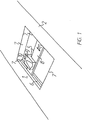
- the operating device 1 shown in FIG. 1 is the center console 2 of a vehicle (not shown) installed. It is used to select a menu, sub-menus or to select a function of the vehicle contained in a submenu.
- the menu, submenu or the function to be selected is on a screen 3 (Fig. 7) shown in the field of vision of the vehicle user.
- a cursor 4 FIG. 7
- the actuating part 5 consists of a carriage 8 with its two ends runs in the guide 6 (due to the perspective representation is only One end of the carriage 8 can be seen) and from a slide 9 which is transverse to Carriage 8 is slidable.
- the directions of movement indicated by a double arrow 10 of the slide 9 are in the following as horizontal, which by a double arrow 11 symbolized directions of movement of the carriage 8 hereinafter referred to as vertical and are so in the claims Are defined.
- FIGS. 2 and 3 The movement of the slide 9 on the carriage 8 is determined by a revolving Timing belt 12 detected and on the rotatable shaft 6 'of the guide 6 in implemented a rotary motion.
- This rotary movement is done by an electric motor 13 detected and converted into commands for the cursor 4.
- the electric motor 13 With the help of the electric motor 13, it is also possible to support the movement of the slide 9 or give a haptic feedback to the operator. This can be done via a path detection (not shown) of the electric motor 13 can be controlled that it is in a middle range of movement of the slide 9, i.e.
- This haptic feedback can be generated, for example, by e.g. a similar force-displacement behavior via permanent magnets in the moving and static part as achieved in the procedure described above with an electric motor (but with fixed tactile feedback) or by also for vertical movement an electric motor is used.
- Fig. 4 is direct instead of one in two directions slidable actuating part selected a structure consisting of a vertical Towards the displaceable body 14 and a pivotable body Actuating part 15 is made.
- the actuator 15 is attached to the body 14 and movable around its rounded front 16.
- an actuating part 18 is on a Plate 19 which is movable in the horizontal and vertical directions.
- the corresponding Arrows 10 and 11 indicate the possible directions of movement of the plate 19 on.
- the movement of the plate 19 is limited by a stop by a frame 20 is formed and against which the operating part 18 at the limits of its range of motion. Through an appropriate transmission and the like. Again, it is also possible to change the position of the actuating part 18 and thus to recognize the plate 19 and thus one of those on the screen 3 selected screen elements.
- a plate 21 corresponding to the Plate 19 is provided, which can only be moved in the vertical direction (arrow 11) is.
- a knob 22 which from the Surface of the plate 21 protrudes and can be rotated.
- the rotary motion the knob 22 can be limited by a mechanical stop be, but it can also be designed as an endless rotary movement.
- the rotary motion itself can create a haptic reaction through detent positions.
- the vertical movement of the plate 21 when it is reached or exceeded Provide tactile, recognizable feedback to the operator at defined positions.
- FIG. 7 shows the relationship between the position of the respective Actuating part (9, 15, 18 or 22) within the operating device of Figures 1 to 6 and the function selected on screen 3, the submenu or the Menu (in the following picture element) written on the screen 3.
- Actuating part for example 9 of Fig. 1 to 3
- a cursor 4 is controlled, the moves on the surface of the screen 3 and its position of position corresponds to the actuating part 9 within the control panel 7 '.
- the control panel 7 ' is for the exemplary embodiment of FIGS. 1 to 3 through the frame 7 limited.
- the surface 3 'of the screen 3 is divided into a number of fields, the borders of which are symbolized by dashed lines. In a left For example, there are four fields in the column, totaling four menus, namely for navigation, radio, air conditioning or on-board computer (BC) are assigned.
- the operating surface 7 'of the operating device is, as shown in FIG. 1, by the Frame 7 limited. It is located in the grip area.
- the actuating part 9 is movable. By moving the operating part 9 a menu or a function of the menu can be selected which is displayed on the screen 3 is arranged at a location which is assigned to the respective position of the actuating part 9 is.
- the control surface 7 ' is in a corresponding Number of fields divided. The fields are also for clarification delimited by dashed lines.
- the actuating part 9 is located at the location shown on the top left Edge of the control surface 7 'is the cursor 4 corresponding in its position the position shown recognizable and thus that assigned to the picture element "Navigation system" menu selected.
- the actuator 9 is moved vertically (down in the figure), it goes into the adjacent field.
- the synchronous moving cursor takes a position in which the next Menu, here "radio setting" is selected. In this way, one can Vertical movement of the actuating part 9 in the manner shown, i.e. when moving Select the desired menu on the left frame 7.
- a trigger switch 22 ' is also provided for selecting the desired menu, that on the edge of the control panel 7 or in the embodiment of FIG. 6 sits next to the actuator 22 and when selected, the selected Menu is selected. It is also possible to use the trigger switch with the actuating part to integrate and as described for example in DE 38 36 555 A, by moving the switch perpendicular to the plane of movement of the Actuating part to trigger the respective switching function.
- the display of the functions is connected with the selection of the respective menu of the menu in the assigned fields of the surface 3 '.
- the desired function can be selected in correspondingly by corresponding adjustment of the actuating part 9 in the field of the control surface 7 ', the field in the surface 3' spatially equivalent.
- the function can be selected using the trigger switch, as for described the menu.
- haptic feedback which can be felt by the operator on the actuating part 9.
- the operator receives immediate information at which point within the control panel 7 'is the actuating part 9.
- FIG. 2 and 3 described the movement of the operating part in the horizontal direction Help of the electric motor 13 are supported.
- control panel 7 can be in the handle area, the surface 3 ' of screen 3 in the field of vision of the vehicle user.
- the haptic feedback reduces the time spent looking around and thus increased driving safety.
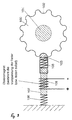
- FIG. 9 shows an embodiment of the invention in which the tactile feedback increases towards the stops and the actuating part about an axis is rotatable.
- the actuating part 100 has an axis of rotation 101. At its edge 102 the actuating part 100 is corrugated, i. H. with a series of notches and Provide surveys.
- the number of notches can be, for example, equal to that Number of menu items.
- the actuating part 100 interacts with an opposite part 103, which it is is a spring-loaded ball. This is spring-loaded and supported against a stop 104. Springs 105 are used to support the ball 103 and 106 are provided. There is also an electromagnet consisting of a Bar magnet 107 and a coil 108 arranged between the springs 105 and 106.
- the position of the ball 103 can be adjusted with the aid of the electromagnet 107/108. in In the position shown, the ball 103 engages in a recess. However, it is a rotary movement of the actuating part 100 is possible. The ball 103 counter to the action of the springs 105 and 106 by the attached to the recess subsequent surveys pushed back to then under the action of the springs 105 and 106 to intervene in the next well.
- the movement of the actuating part initially takes place a constantly increasing counterforce up to the maximum pushing back of the Ball 103 through the collection and a subsequent constant reduction the actuating force, which even supports the rotary movement of the Actuator can go under the action of springs 105 and 106.
- the ball 103 can also act under the action of the electromagnet 107/108 must be pressed into the recess of the edge 102 with great force.
- the Spring 105 can even go to block, for example. So that is the rotary motion of the actuator 100 blocked. This can serve, for example, to simulate a mechanical stop of the actuating part 100.
- the force acting on the ball 103 is variable Current is applied to the coil 108 during the rotary movement of the actuating part to vary, thereby, for example, during part of the rotational movement the mechanical resistance exerted by the ball 103, to keep constant.
- the ball 103 corresponding to that through the edge 102 given movement path moved by the electromagnet 107/108. This changes the shape of the edge 102 to the operator during this portion of the Rotational movement not noticeable.
- the solenoid 107/108 becomes ineffective.
- the feathers 105 and 106 ensure that tactile feedback is received and guaranteed thus an emergency operation of the operating device.
Claims (17)
- Dispositif de commande des fonctions d'un véhicule à partir d'un menu, représentées symboliquement sur un écran et que l'on peut sélectionner par une pièce d'actionnement, selon lequel, la partie d'actionnement (9, 15, 18, 22) peut être déplacée entre des butées mécaniques, dans une position qui correspond à la position du symbole de la fonction sélectionnée sur la surface de l'écran image (3') et selon lequel en cas de variation de la fonction sélectionnée par des mouvements de la pièce d'actionnement, il y a un message en retour, haptique pour la pièce d'actionnement.
- Dispositif de commande selon la revendication 1,
caractérisé en ce que
l'intensité du message en retour, haptique, augmente en direction des butées (7,17). - Dispositif de commande selon la revendication 1 ou 2,
caractérisé en ce que
la pièce d'actionnement peut être déplacée dans la direction verticale (11). - Dispositif de commande selon l'une des revendications 1 à 3,
caractérisé en ce que
la pièce d'actionnement peut être déplacée dans la direction horizontale (10). - Dispositif de commande selon la revendication 4,
caractérisé en ce que
la pièce d'actionnement possède une transmission mécanique (12) suivie d'une installation de détection électrique. - Dispositif de commande selon l'une des revendications 1 à 3,
caractérisé en ce que
la pièce d'actionnement (22) peut tourner autour d'un axe. - Dispositif de commande selon l'une des revendications 1 à 3,
caractérisé en ce que
la pièce d'actionnement (15) peut basculer dans la direction horizontale. - Dispositif de commande selon l'une des revendications 1 à 7,
caractérisé en ce que
la pièce d'actionnement peut se déplacer dans un cadre (7, 17). - Dispositif de commande selon l'une des revendications 1 à 8,
caractérisé en ce que
la pièce d'actionnement comporte un commutateur de déclenchement (22') qui déclenche la fonction sélectionnée. - Dispositif de commande selon la revendication 9,
caractérisé en ce que
le commutateur de déclenchement peut être déplacé avec une pièce d'actionnement. - Dispositif de commande selon la revendication 9 ou 10,
caractérisé en ce que
le commutateur de déclenchement est intégré à la pièce d'actionnement. - Dispositif de commande selon la revendication 2,
caractérisé en ce que
la pièce d'actionnement (2) peut tourner autour d'un axe et présente un bord moleté et coopère avec une pièce complémentaire (103) coulissante perpendiculairement à l'axe de rotation (101) de la pièce d'actionnement. - Dispositif de commande selon la revendication 12,
caractérisé en ce que
la pièce complémentaire est montée à rotation. - Dispositif de commande selon la revendication 12 ou 13,
caractérisé en ce que
la pièce complémentaire est montée à ressort. - Dispositif de commande selon l'une des revendications 12 à 14,
caractérisé en ce que
la pièce complémentaire peut être réglée en position par rapport à la pièce d'actionnement. - Dispositif de commande selon la revendication 15,
caractérisé en ce que
la pièce complémentaire peut être réglée dans sa position de fin de course dans laquelle le mouvement de rotation de la pièce d'actionnement est bloqué. - Dispositif de commande selon l'une des revendications 12 à 1-,
caractérisé en ce que
la pièce complémentaire est déplacée par un électroaimant.
Applications Claiming Priority (4)
| Application Number | Priority Date | Filing Date | Title |
|---|---|---|---|
| DE19610700 | 1996-03-19 | ||
| DE19610700A DE19610700A1 (de) | 1996-03-19 | 1996-03-19 | Bedienvorrichtung für menügesteuerte Funktionen eines Fahrzeugs |
| DE19646226 | 1996-11-08 | ||
| DE19646226A DE19646226A1 (de) | 1996-03-19 | 1996-11-08 | Bedienvorrichtung für menügesteuerte Funktionen eines Fahrzeugs |
Publications (4)
| Publication Number | Publication Date |
|---|---|
| EP0796756A2 EP0796756A2 (fr) | 1997-09-24 |
| EP0796756A3 EP0796756A3 (fr) | 1998-04-29 |
| EP0796756B1 true EP0796756B1 (fr) | 2003-01-15 |
| EP0796756B2 EP0796756B2 (fr) | 2006-10-11 |
Family
ID=26023926
Family Applications (1)
| Application Number | Title | Priority Date | Filing Date |
|---|---|---|---|
| EP97102392A Expired - Lifetime EP0796756B2 (fr) | 1996-03-19 | 1997-02-14 | Dispositif de commande de fonctions d'un véhicule contrôlés à partir d'un menu |
Country Status (5)
| Country | Link |
|---|---|
| US (1) | US5956016A (fr) |
| EP (1) | EP0796756B2 (fr) |
| JP (1) | JP4035196B2 (fr) |
| DE (2) | DE19646226A1 (fr) |
| ES (1) | ES2190488T5 (fr) |
Families Citing this family (121)
| Publication number | Priority date | Publication date | Assignee | Title |
|---|---|---|---|---|
| US5666138A (en) | 1994-11-22 | 1997-09-09 | Culver; Craig F. | Interface control |
| US5825308A (en) | 1996-11-26 | 1998-10-20 | Immersion Human Interface Corporation | Force feedback interface having isotonic and isometric functionality |
| SE519661C2 (sv) * | 1996-02-23 | 2003-03-25 | Immersion Corp | Pekdon och förfarande för markering av grafiska detaljer på en display med sensorisk återkoppling vid påträffande av nämnda detalj |
| US6411276B1 (en) | 1996-11-13 | 2002-06-25 | Immersion Corporation | Hybrid control of haptic feedback for host computer and interface device |
| US6956558B1 (en) * | 1998-03-26 | 2005-10-18 | Immersion Corporation | Rotary force feedback wheels for remote control devices |
| US6686911B1 (en) | 1996-11-26 | 2004-02-03 | Immersion Corporation | Control knob with control modes and force feedback |
| US6278441B1 (en) * | 1997-01-09 | 2001-08-21 | Virtouch, Ltd. | Tactile interface system for electronic data display system |
| US6292174B1 (en) | 1997-08-23 | 2001-09-18 | Immersion Corporation | Enhanced cursor control using limited-workspace force feedback devices |
| US6448977B1 (en) * | 1997-11-14 | 2002-09-10 | Immersion Corporation | Textures and other spatial sensations for a relative haptic interface device |
| US6252583B1 (en) | 1997-11-14 | 2001-06-26 | Immersion Corporation | Memory and force output management for a force feedback system |
| US6243078B1 (en) | 1998-06-23 | 2001-06-05 | Immersion Corporation | Pointing device with forced feedback button |
| US6256011B1 (en) * | 1997-12-03 | 2001-07-03 | Immersion Corporation | Multi-function control device with force feedback |
| US6225980B1 (en) * | 1998-02-06 | 2001-05-01 | Carnegie Mellon University | Multi-functional, rotary dial input device for portable computers |
| US6292172B1 (en) * | 1998-03-20 | 2001-09-18 | Samir B. Makhlouf | System and method for controlling and integrating various media devices in a universally controlled system |
| FR2777367A1 (fr) * | 1998-04-09 | 1999-10-15 | Bruno Mortier | Dispositif de pointage pour ordinateurs portables essentiellement |
| US6300938B1 (en) | 1998-04-13 | 2001-10-09 | Immersion Corporation | Multiple-cylinder control device for computers and other electronic apparatus |
| DE19821899C2 (de) * | 1998-05-15 | 2001-06-13 | Siemens Ag | Drehschalter, insbesondere Zündanlaßschalter |
| JPH11339580A (ja) | 1998-05-22 | 1999-12-10 | Alps Electric Co Ltd | ステアリング装置 |
| US6429846B2 (en) | 1998-06-23 | 2002-08-06 | Immersion Corporation | Haptic feedback for touchpads and other touch controls |
| US6697043B1 (en) | 1999-12-21 | 2004-02-24 | Immersion Corporation | Haptic interface device and actuator assembly providing linear haptic sensations |
| US6707443B2 (en) | 1998-06-23 | 2004-03-16 | Immersion Corporation | Haptic trackball device |
| US6184868B1 (en) | 1998-09-17 | 2001-02-06 | Immersion Corp. | Haptic feedback control devices |
| DE19855005A1 (de) * | 1998-11-20 | 2000-05-25 | Inst Halbleiterphysik Gmbh | Mobile Telekommunikationseinheit mit verbessertem Bedienungskomfort |
| EP1028572A1 (fr) * | 1999-02-12 | 2000-08-16 | Alcatel | Elément de commande pour un appareil commandé par menus et radiotéléphone comportant un tel élément |
| NO990891L (no) * | 1999-02-25 | 2000-08-26 | Steinar Pedersen | Kommunikasjonsredskap med singulær operasjonstast |
| US6424356B2 (en) | 1999-05-05 | 2002-07-23 | Immersion Corporation | Command of force sensations in a forceback system using force effect suites |
| US7061466B1 (en) * | 1999-05-07 | 2006-06-13 | Immersion Corporation | Force feedback device including single-phase, fixed-coil actuators |
| US8169402B2 (en) | 1999-07-01 | 2012-05-01 | Immersion Corporation | Vibrotactile haptic feedback devices |
| US6693622B1 (en) | 1999-07-01 | 2004-02-17 | Immersion Corporation | Vibrotactile haptic feedback devices |
| US7561142B2 (en) * | 1999-07-01 | 2009-07-14 | Immersion Corporation | Vibrotactile haptic feedback devices |
| DE19937463B4 (de) * | 1999-08-07 | 2004-12-02 | Volkswagen Ag | Verfahren zum Betrieb einer Multifunktionsbedieneinrichtung bei Kraftfahrzeugen, sowie Multifunktionsbedieneinrichtung selbst |
| DE19941960A1 (de) * | 1999-09-03 | 2001-03-08 | Volkswagen Ag | Multifunktions-Bedienelement |
| DE20080209U1 (de) | 1999-09-28 | 2001-08-09 | Immersion Corp | Steuerung von haptischen Empfindungen für Schnittstellenvorrichtungen mit Vibrotaktiler Rückkopplung |
| US6714213B1 (en) | 1999-10-08 | 2004-03-30 | General Electric Company | System and method for providing interactive haptic collision detection |
| NO20004375L (no) * | 1999-12-06 | 2001-06-07 | Ziad Badarneh | System og fremgangsmåte for fremvisning og assistering av manipuleringsbevegelser ved betjening av en manöverinnretning foret funksjonsutstyr |
| US6693626B1 (en) | 1999-12-07 | 2004-02-17 | Immersion Corporation | Haptic feedback using a keyboard device |
| US6822635B2 (en) | 2000-01-19 | 2004-11-23 | Immersion Corporation | Haptic interface for laptop computers and other portable devices |
| NO20005119L (no) * | 2000-02-18 | 2001-08-20 | Ziad Badarneh | Interaktivt system |
| DE10021065A1 (de) * | 2000-04-28 | 2001-10-31 | Bosch Gmbh Robert | Bedieneinheit |
| SE0002698D0 (sv) | 2000-07-14 | 2000-07-14 | Rolf Stroemberg | Pekdon med slinga och roterbara stavar |
| DE10041935A1 (de) * | 2000-08-25 | 2002-03-07 | Kostal Leopold Gmbh & Co Kg | Drehsteller |
| US7084854B1 (en) | 2000-09-28 | 2006-08-01 | Immersion Corporation | Actuator for providing tactile sensations and device for directional tactile sensations |
| DE10063347A1 (de) * | 2000-12-19 | 2002-06-20 | Siemens Ag | Vorrichtung zur komfortablen Steuerung und Manipulation von virtuellen Objekten für ein Endgerät zur Ein-/Ausgabe, Übertragung und/oder Speicherung von Text-, Ton- und/oder Bildinformation |
| US7146260B2 (en) | 2001-04-24 | 2006-12-05 | Medius, Inc. | Method and apparatus for dynamic configuration of multiprocessor system |
| US10298735B2 (en) | 2001-04-24 | 2019-05-21 | Northwater Intellectual Property Fund L.P. 2 | Method and apparatus for dynamic configuration of a multiprocessor health data system |
| DE10120618A1 (de) | 2001-04-26 | 2002-10-31 | Kostal Leopold Gmbh & Co Kg | Drehsteller |
| DE10126421B4 (de) * | 2001-05-31 | 2005-07-14 | Caa Ag | Fahrzeugrechner-System und Verfahren zur Steuerung eines Cursors für ein Fahrzeugrechner-System |
| CA2350910A1 (fr) * | 2001-06-20 | 2002-12-20 | Kevin Tuer | Tableau de bord reconfigurable |
| NO20020895L (no) * | 2001-06-27 | 2002-12-30 | Ziad Badarneh | Interaktivt system i tilknytning til elektronisk utstyr |
| DE10153013B4 (de) * | 2001-10-26 | 2006-09-07 | Leopold Kostal Gmbh & Co. Kg | Drehstelleranordnung mit Hubmagnet, sowie Hubmagnet mit elektrischer Überwachung |
| DE10153002B4 (de) * | 2001-10-26 | 2006-09-07 | Leopold Kostal Gmbh & Co. Kg | Drehsteller mit Hubmagnet, sowie Hubmagnet |
| US7178049B2 (en) | 2002-04-24 | 2007-02-13 | Medius, Inc. | Method for multi-tasking multiple Java virtual machines in a secure environment |
| US7081883B2 (en) * | 2002-05-14 | 2006-07-25 | Michael Changcheng Chen | Low-profile multi-channel input device |
| DE10222052B4 (de) * | 2002-05-17 | 2022-06-30 | Volkswagen Ag | Verfahren und Einrichtung zum Betrieb einer multifunktionalen Bedieneinrichtung in einem Kraftfahrzeug |
| DE10305668A1 (de) * | 2002-09-24 | 2004-03-25 | Behr-Hella Thermocontrol Gmbh | Betätigungseinrichtung sowie Verwendung derselben |
| US8830161B2 (en) | 2002-12-08 | 2014-09-09 | Immersion Corporation | Methods and systems for providing a virtual touch haptic effect to handheld communication devices |
| US8059088B2 (en) | 2002-12-08 | 2011-11-15 | Immersion Corporation | Methods and systems for providing haptic messaging to handheld communication devices |
| AU2003297716A1 (en) | 2002-12-08 | 2004-06-30 | Immersion Corporation | Methods and systems for providing haptic messaging to handheld communication devices |
| US20040118664A1 (en) * | 2002-12-19 | 2004-06-24 | Lear Corporation | Multifunction switch and method of using same |
| EP1431996A3 (fr) * | 2002-12-20 | 2006-08-09 | Siemens Aktiengesellschaft | Dispositif d'entrée pour un appareil électrique |
| JP3988646B2 (ja) * | 2003-01-17 | 2007-10-10 | 日産自動車株式会社 | 車両用操作装置 |
| US7605802B2 (en) * | 2003-01-31 | 2009-10-20 | Volkswagen Aktiengesellschaft | Operator device with haptic feedback |
| EP2213501A3 (fr) | 2003-03-31 | 2012-05-09 | Timothy R. Pryor | Panneaux d'instruments reconfigurables pour véhicule |
| DE10331776B3 (de) | 2003-07-11 | 2005-05-04 | Siemens Ag | Bedienvorrichtung |
| JP4220355B2 (ja) * | 2003-11-10 | 2009-02-04 | アルプス電気株式会社 | 力覚付与型入力装置 |
| JP4180491B2 (ja) * | 2003-11-10 | 2008-11-12 | アルプス電気株式会社 | 力覚付与型入力装置 |
| DE102004022846B4 (de) * | 2003-11-20 | 2010-09-09 | Preh Gmbh | Bedienelement mit programmierbarer Haptik |
| US7570247B2 (en) * | 2003-11-24 | 2009-08-04 | Avago Technologies Ecbu Ip (Singapore) Pte. Ltd. | Modular assembly for a self-indexing computer pointing device |
| US7429976B2 (en) * | 2003-11-24 | 2008-09-30 | Avago Technologies Ecbu Ip (Singapore) Pte. Ltd. | Compact pointing device |
| US7158115B2 (en) * | 2003-11-24 | 2007-01-02 | Avago Technologies Ecbu Ip (Singapore) Pte. Ltd. | Spring system for re-centering a movable object |
| EP1557744B1 (fr) * | 2004-01-20 | 2008-04-16 | Sony Deutschland GmbH | Saisie de données commandée par touches haptiques |
| US7522154B2 (en) * | 2004-07-29 | 2009-04-21 | Avago Technologies Ecbu Ip (Singapore) Pte. Ltd. | Slide pad notebook pointing device with hidden spring system |
| DE102004040886A1 (de) * | 2004-08-24 | 2006-03-02 | Volkswagen Ag | Bedienvorrichtung für ein Kraftfahrzeug |
| US7978173B2 (en) * | 2005-01-14 | 2011-07-12 | Avago Technologies Ecbu Ip (Singapore) Pte. Ltd. | Pointing device including a moveable puck with mechanical detents |
| US7586480B2 (en) | 2005-02-28 | 2009-09-08 | Avago Technologies Ecbu Ip (Singapore) Pte. Ltd. | Hybrid pointing device |
| US8561008B2 (en) * | 2005-03-10 | 2013-10-15 | Siemens Aktiengesellschaft | Presentation of hierarchical software structures |
| US20060267994A1 (en) * | 2005-05-31 | 2006-11-30 | Lucent Technologies Inc. | Armrest personal digital media system |
| DE102005042883B4 (de) * | 2005-06-02 | 2008-05-08 | Preh Gmbh | Bestätigungsvorrichtung mit Mitteln zum Blockieren von Bewegungen |
| DE102005043587B4 (de) * | 2005-06-02 | 2009-04-02 | Preh Gmbh | Drehsteller mit programmierbarer Haptik |
| DE102006018518B4 (de) | 2005-07-19 | 2022-04-07 | Preh Gmbh | Bedienknopf mit integrierter Funktionalität |
| JP4836050B2 (ja) * | 2005-09-15 | 2011-12-14 | 株式会社デンソー | 車載電子機器用入力システム |
| JP4555201B2 (ja) * | 2005-09-21 | 2010-09-29 | 株式会社東海理化電機製作所 | 入力装置 |
| US20070080944A1 (en) * | 2005-10-07 | 2007-04-12 | Parees Benjamin M | Mouse with disengageable scroll function |
| US7520528B2 (en) * | 2005-12-06 | 2009-04-21 | Mazda Motor Corporation | Steering wheel assembly with airbag module |
| JP5231715B2 (ja) * | 2005-12-07 | 2013-07-10 | トヨタ自動車株式会社 | 入力装置 |
| US7701440B2 (en) * | 2005-12-19 | 2010-04-20 | Avago Technologies Ecbu Ip (Singapore) Pte. Ltd. | Pointing device adapted for small handheld devices having two display modes |
| KR100932357B1 (ko) * | 2006-01-26 | 2009-12-16 | 아바고 테크놀로지스 이씨비유 아이피 (싱가포르) 피티이 리미티드 | 포인팅 디바이스 및 이를 이용한 디스플레이 상의 아이템선택 방법 |
| DE102006007600B4 (de) * | 2006-02-18 | 2016-12-15 | Leopold Kostal Gmbh & Co. Kg | Drehsteller für elektrische oder elektronische Gräte in einem Kraftfahrzeug |
| DE102006015294A1 (de) * | 2006-03-29 | 2007-10-11 | Preh Gmbh | Blockiereinrichtung zur zumindest teilweisen Blockierung einer Relativbewegung |
| US20070247446A1 (en) * | 2006-04-25 | 2007-10-25 | Timothy James Orsley | Linear positioning input device |
| US20090201248A1 (en) * | 2006-07-05 | 2009-08-13 | Radu Negulescu | Device and method for providing electronic input |
| US7889176B2 (en) * | 2006-07-18 | 2011-02-15 | Avago Technologies General Ip (Singapore) Pte. Ltd. | Capacitive sensing in displacement type pointing devices |
| DE102006042430B4 (de) * | 2006-09-09 | 2008-09-18 | Preh Gmbh | Rasteinrichtung für ein Bedienelement |
| JP4690299B2 (ja) * | 2006-12-14 | 2011-06-01 | 株式会社東海理化電機製作所 | 遠隔操作式入力装置 |
| DE102007013383B3 (de) * | 2007-03-16 | 2008-09-04 | Preh Gmbh | Bedienelement mit mechanischer Rastung |
| US20080297491A1 (en) * | 2007-05-29 | 2008-12-04 | Adkins Gordon K | Stylus for a touch-screen device |
| US8232963B2 (en) * | 2007-08-27 | 2012-07-31 | Avago Technologies Ecbu Ip (Singapore) Pte. Ltd. | Control and data entry apparatus |
| US20090058802A1 (en) * | 2007-08-27 | 2009-03-05 | Avago Technologies Ecbu Ip (Singapore) Pte. Ltd. | Input device |
| US7978175B2 (en) * | 2007-11-23 | 2011-07-12 | Avago Technologies Ecbu Ip (Singapore) Pte. Ltd. | Magnetic re-centering mechanism for a capacitive input device |
| US20090135157A1 (en) * | 2007-11-27 | 2009-05-28 | Avago Technologies Ecbu Ip (Singapore) Pte. Ltd. | Capacitive Sensing Input Device with Reduced Sensitivity to Humidity and Condensation |
| KR100948667B1 (ko) * | 2007-12-10 | 2010-03-18 | 김성수 | 단말기 화면에 좌표를 입력하는 핑거 마우스 |
| EP2083343A1 (fr) * | 2008-01-28 | 2009-07-29 | Tescom Europe Gmbh & Co. Kg | Régulateur de pression |
| US9513704B2 (en) * | 2008-03-12 | 2016-12-06 | Immersion Corporation | Haptically enabled user interface |
| DE102008060256B4 (de) * | 2008-12-03 | 2018-10-04 | Behr-Hella Thermocontrol Gmbh | Bedienelement mit einstellbarer Haptik |
| US9358924B1 (en) | 2009-05-08 | 2016-06-07 | Eagle Harbor Holdings, Llc | System and method for modeling advanced automotive safety systems |
| DE102009022471A1 (de) * | 2009-05-25 | 2010-12-02 | Valeo Schalter Und Sensoren Gmbh | Manuell bedienbare Schaltvorrichtung und eine elektronische Auswerteeinrichtung |
| JP4935875B2 (ja) * | 2009-09-04 | 2012-05-23 | 株式会社デンソー | 操作装置 |
| US8542105B2 (en) | 2009-11-24 | 2013-09-24 | Immersion Corporation | Handheld computer interface with haptic feedback |
| DE102010005360A1 (de) * | 2010-01-21 | 2011-07-28 | Bernstein AG, 32457 | Fußschalter |
| JP2011227734A (ja) * | 2010-04-20 | 2011-11-10 | Tokai Rika Co Ltd | 入力装置 |
| US20110309920A1 (en) * | 2010-06-21 | 2011-12-22 | Brooks James D | Tactile prompting system and method for tactually prompting an operator of a rail vehicle |
| JP5263243B2 (ja) * | 2010-09-02 | 2013-08-14 | 株式会社デンソー | 車両用表示装置 |
| DE102010055831A1 (de) * | 2010-12-23 | 2012-06-28 | Inventus Engineering Gmbh | Übertragungsvorrichtung |
| CN102274635A (zh) * | 2011-07-30 | 2011-12-14 | 周海涛 | 一种游戏控制器 |
| US9582178B2 (en) | 2011-11-07 | 2017-02-28 | Immersion Corporation | Systems and methods for multi-pressure interaction on touch-sensitive surfaces |
| DE102012200313A1 (de) * | 2012-01-11 | 2013-07-11 | BSH Bosch und Siemens Hausgeräte GmbH | Drehregler für ein Haushaltsgerät |
| DE102012002304A1 (de) * | 2012-02-06 | 2013-08-08 | Audi Ag | Vorrichtung zum automatisierten Führen eines Kraftwagens und Verfahren zum Betreiben eines Kraftwagens |
| DE102013102495A1 (de) * | 2013-03-13 | 2014-09-18 | Dr. Ing. H.C. F. Porsche Aktiengesellschaft | Mittelkonsolenanordnung für ein Kraftfahrzeug |
| EP3074836B1 (fr) | 2013-11-29 | 2019-08-28 | Marquardt GmbH | Organe de réglage, en particulier pour véhicule automobile |
| DE102014008040A1 (de) * | 2014-05-28 | 2015-12-03 | GM Global Technology Operations LLC (n. d. Gesetzen des Staates Delaware) | Kraftfahrzeug-Ein-/Ausgabevorrichtung und -verfahren |
| DE102022115084A1 (de) | 2022-06-15 | 2023-12-21 | Signata GmbH | Stellvorrichtung für ein Fahrzeug und Verfahren zum Betreiben einer Stellvorrichtung |
Citations (5)
| Publication number | Priority date | Publication date | Assignee | Title |
|---|---|---|---|---|
| DE3514438C1 (de) * | 1985-04-20 | 1986-09-18 | Porsche Ag | Zentrale Bedienungsein- und Informationsausgabe fuer Zusatzgeraete von Fahrzeugen |
| DE3836555A1 (de) * | 1988-10-27 | 1990-05-10 | Bayerische Motoren Werke Ag | Multifunktions-bedieneinrichtung |
| DE4205875A1 (de) * | 1992-02-26 | 1993-09-02 | Vdo Schindling | Bedienvorrichtung |
| US5327162A (en) * | 1992-03-17 | 1994-07-05 | Alps Electric Co., Ltd. | X-y direction input device |
| DE4400790A1 (de) * | 1993-11-10 | 1995-05-18 | Johannes Dipl Ing Geisen | Vorrichtung und/oder Verfahren zur Kommunikation mit DV-Anlagen bzw. Bedienungsvorrichtungen |
Family Cites Families (12)
| Publication number | Priority date | Publication date | Assignee | Title |
|---|---|---|---|---|
| JPS5557932A (en) * | 1978-10-25 | 1980-04-30 | Olympus Optical Co Ltd | Digital switch |
| DE3346370A1 (de) * | 1983-12-22 | 1985-07-11 | Robert Bosch Gmbh, 7000 Stuttgart | Verfahren zur anzeige von informationen, vorzugsweise in einem kraftfahrzeug |
| US4670743A (en) * | 1985-01-31 | 1987-06-02 | General Instrument Corporation | Keyboard cursor controller |
| US4868549A (en) * | 1987-05-18 | 1989-09-19 | International Business Machines Corporation | Feedback mouse |
| US4910503A (en) * | 1987-06-15 | 1990-03-20 | Brodsky Stephen L | Multi-function input device and system |
| US4947097A (en) * | 1989-06-12 | 1990-08-07 | The Grass Valley Group, Inc. | Automatic switching of motion control with tactile feedback |
| DE4034166A1 (de) * | 1990-10-26 | 1992-04-30 | Cherry Mikroschalter Gmbh | Cursorvorrichtung mit nullpunktrueckstellung |
| NL194053C (nl) * | 1990-12-05 | 2001-05-03 | Koninkl Philips Electronics Nv | Inrichting met een rotatiesymmetrisch lichaam. |
| DE4141110A1 (de) * | 1991-12-13 | 1993-06-17 | Haschkamp Geb Dreefs | Drehwahlschalter mit einer durch eine rastung festlegbaren schaltnockenwelle oder schaltnockenscheibe |
| US5396266A (en) * | 1993-06-08 | 1995-03-07 | Technical Research Associates, Inc. | Kinesthetic feedback apparatus and method |
| US5721566A (en) * | 1995-01-18 | 1998-02-24 | Immersion Human Interface Corp. | Method and apparatus for providing damping force feedback |
| EP0701926B2 (fr) * | 1994-09-13 | 2004-07-28 | Volkswagen Aktiengesellschaft | Dispositif de commande multifonctions |
-
1996
- 1996-11-08 DE DE19646226A patent/DE19646226A1/de not_active Withdrawn
-
1997
- 1997-02-14 DE DE59709124T patent/DE59709124D1/de not_active Expired - Lifetime
- 1997-02-14 EP EP97102392A patent/EP0796756B2/fr not_active Expired - Lifetime
- 1997-02-14 ES ES97102392T patent/ES2190488T5/es not_active Expired - Lifetime
- 1997-03-18 JP JP06483897A patent/JP4035196B2/ja not_active Expired - Lifetime
- 1997-03-19 US US08/820,904 patent/US5956016A/en not_active Expired - Lifetime
Patent Citations (5)
| Publication number | Priority date | Publication date | Assignee | Title |
|---|---|---|---|---|
| DE3514438C1 (de) * | 1985-04-20 | 1986-09-18 | Porsche Ag | Zentrale Bedienungsein- und Informationsausgabe fuer Zusatzgeraete von Fahrzeugen |
| DE3836555A1 (de) * | 1988-10-27 | 1990-05-10 | Bayerische Motoren Werke Ag | Multifunktions-bedieneinrichtung |
| DE4205875A1 (de) * | 1992-02-26 | 1993-09-02 | Vdo Schindling | Bedienvorrichtung |
| US5327162A (en) * | 1992-03-17 | 1994-07-05 | Alps Electric Co., Ltd. | X-y direction input device |
| DE4400790A1 (de) * | 1993-11-10 | 1995-05-18 | Johannes Dipl Ing Geisen | Vorrichtung und/oder Verfahren zur Kommunikation mit DV-Anlagen bzw. Bedienungsvorrichtungen |
Also Published As
| Publication number | Publication date |
|---|---|
| JPH1039786A (ja) | 1998-02-13 |
| JP4035196B2 (ja) | 2008-01-16 |
| EP0796756A2 (fr) | 1997-09-24 |
| DE59709124D1 (de) | 2003-02-20 |
| DE19646226A1 (de) | 1998-05-14 |
| ES2190488T3 (es) | 2003-08-01 |
| ES2190488T5 (es) | 2007-05-01 |
| US5956016A (en) | 1999-09-21 |
| EP0796756A3 (fr) | 1998-04-29 |
| EP0796756B2 (fr) | 2006-10-11 |
Similar Documents
| Publication | Publication Date | Title |
|---|---|---|
| EP0796756B1 (fr) | Dispositif de commande de fonctions d'un véhicule contrôlés à partir d'un menu | |
| DE19610700A1 (de) | Bedienvorrichtung für menügesteuerte Funktionen eines Fahrzeugs | |
| DE60033597T2 (de) | Eingabeeinrichtung, montiert in einem Kraftfahrzeug | |
| EP0893750B2 (fr) | Multifunctional joystick | |
| EP2062121B1 (fr) | Tablette ou ecran tactile et element de commande pour tablette ou ecran tactile | |
| DE10139694B4 (de) | Multifunktions-Bedieneinrichtung | |
| EP0796766B1 (fr) | Dispositif de commande multifonctions pour un véhicule | |
| EP1034470B1 (fr) | Dispositif pour commander un ecran d'affichage | |
| EP1262740B1 (fr) | Système d'ordinateur véhiculaire et procédé de commande d'un curseur pour système d'ordinateur véhiculaire | |
| DE10331776B3 (de) | Bedienvorrichtung | |
| EP2920665B1 (fr) | Dispositif de commande pour un appareil de véhicule | |
| DE60215882T2 (de) | Handeingabevorrichtung | |
| EP2550581A1 (fr) | Dispositif d'entrée avec informations haptiques en retour | |
| DE19916924A1 (de) | Kraftfahrzeug mit einer Wähleinrichtung | |
| DE19731285A1 (de) | Bedienelement | |
| EP2984667A1 (fr) | Dispositif permettant de commander plusieurs fonctions dans un véhicule à moteur | |
| EP3352533A1 (fr) | Console de réglage de l'éclairage pourvue d'encodeur double | |
| DE102005033923A1 (de) | Bedienelement mit berührungsempfindlicher Bedienoberfläche | |
| DE60024173T2 (de) | Eingabeeinrichtung für ein Kraftfahrzeug die eine einzige manuelle Bedieneinheit aufweist zur Bedienung von verschiedenen im Kraftfahrzeug montierten, elektronischen Geräten | |
| EP1122633A2 (fr) | Dispositif pour commander un écran d'affichage | |
| DE10003140C1 (de) | Betriebsarten-Wähleinrichtung für Fahrzeuggetriebe | |
| DE102005025887B4 (de) | Bedieneinrichtung für ein Kraftfahrzeug und Verfahren zum Bedienen einer Bedieneinrichtung | |
| DE102010012247A1 (de) | Eingabevorrichtung mit haptischer Rückmeldung | |
| DE10131039C2 (de) | Bedienelement für ein Fahrzeugrechner-System und Fahrzeugrechner-System | |
| EP3658799B1 (fr) | Dispositif de commutation comprenant un encliquetage magnétique |
Legal Events
| Date | Code | Title | Description |
|---|---|---|---|
| PUAI | Public reference made under article 153(3) epc to a published international application that has entered the european phase |
Free format text: ORIGINAL CODE: 0009012 |
|
| AK | Designated contracting states |
Kind code of ref document: A2 Designated state(s): DE ES FR GB IT |
|
| PUAL | Search report despatched |
Free format text: ORIGINAL CODE: 0009013 |
|
| AK | Designated contracting states |
Kind code of ref document: A3 Designated state(s): DE ES FR GB IT |
|
| 17P | Request for examination filed |
Effective date: 19981009 |
|
| GRAH | Despatch of communication of intention to grant a patent |
Free format text: ORIGINAL CODE: EPIDOS IGRA |
|
| GRAH | Despatch of communication of intention to grant a patent |
Free format text: ORIGINAL CODE: EPIDOS IGRA |
|
| GRAA | (expected) grant |
Free format text: ORIGINAL CODE: 0009210 |
|
| AK | Designated contracting states |
Kind code of ref document: B1 Designated state(s): DE ES FR GB IT |
|
| REG | Reference to a national code |
Ref country code: GB Ref legal event code: FG4D Free format text: NOT ENGLISH |
|
| REF | Corresponds to: |
Ref document number: 59709124 Country of ref document: DE Date of ref document: 20030220 Kind code of ref document: P |
|
| GBT | Gb: translation of ep patent filed (gb section 77(6)(a)/1977) |
Effective date: 20030307 |
|
| REG | Reference to a national code |
Ref country code: ES Ref legal event code: FG2A Ref document number: 2190488 Country of ref document: ES Kind code of ref document: T3 |
|
| ET | Fr: translation filed | ||
| PLBQ | Unpublished change to opponent data |
Free format text: ORIGINAL CODE: EPIDOS OPPO |
|
| PLBI | Opposition filed |
Free format text: ORIGINAL CODE: 0009260 |
|
| PLAX | Notice of opposition and request to file observation + time limit sent |
Free format text: ORIGINAL CODE: EPIDOSNOBS2 |
|
| 26 | Opposition filed |
Opponent name: DAIMLERCHRYSLER AG Effective date: 20031009 |
|
| PLAX | Notice of opposition and request to file observation + time limit sent |
Free format text: ORIGINAL CODE: EPIDOSNOBS2 |
|
| PLBB | Reply of patent proprietor to notice(s) of opposition received |
Free format text: ORIGINAL CODE: EPIDOSNOBS3 |
|
| PLAY | Examination report in opposition despatched + time limit |
Free format text: ORIGINAL CODE: EPIDOSNORE2 |
|
| PLBC | Reply to examination report in opposition received |
Free format text: ORIGINAL CODE: EPIDOSNORE3 |
|
| PLAT | Information related to reply to examination report in opposition deleted |
Free format text: ORIGINAL CODE: EPIDOSDORE3 |
|
| PLAY | Examination report in opposition despatched + time limit |
Free format text: ORIGINAL CODE: EPIDOSNORE2 |
|
| PLBC | Reply to examination report in opposition received |
Free format text: ORIGINAL CODE: EPIDOSNORE3 |
|
| RIC2 | Information provided on ipc code assigned after grant |
Ipc: G06F 3/033 20060101ALI20060613BHEP Ipc: B60K 37/06 20060101AFI20060613BHEP |
|
| PUAH | Patent maintained in amended form |
Free format text: ORIGINAL CODE: 0009272 |
|
| STAA | Information on the status of an ep patent application or granted ep patent |
Free format text: STATUS: PATENT MAINTAINED AS AMENDED |
|
| 27A | Patent maintained in amended form |
Effective date: 20061011 |
|
| AK | Designated contracting states |
Kind code of ref document: B2 Designated state(s): DE ES FR GB IT |
|
| GBTA | Gb: translation of amended ep patent filed (gb section 77(6)(b)/1977) | ||
| ET3 | Fr: translation filed ** decision concerning opposition | ||
| REG | Reference to a national code |
Ref country code: ES Ref legal event code: DC2A Date of ref document: 20061130 Kind code of ref document: T5 |
|
| REG | Reference to a national code |
Ref country code: FR Ref legal event code: PLFP Year of fee payment: 20 |
|
| PGFP | Annual fee paid to national office [announced via postgrant information from national office to epo] |
Ref country code: IT Payment date: 20160229 Year of fee payment: 20 Ref country code: ES Payment date: 20160223 Year of fee payment: 20 |
|
| PGFP | Annual fee paid to national office [announced via postgrant information from national office to epo] |
Ref country code: GB Payment date: 20160222 Year of fee payment: 20 Ref country code: FR Payment date: 20160222 Year of fee payment: 20 |
|
| PGFP | Annual fee paid to national office [announced via postgrant information from national office to epo] |
Ref country code: DE Payment date: 20160324 Year of fee payment: 20 |
|
| REG | Reference to a national code |
Ref country code: DE Ref legal event code: R071 Ref document number: 59709124 Country of ref document: DE |
|
| REG | Reference to a national code |
Ref country code: GB Ref legal event code: PE20 Expiry date: 20170213 |
|
| PG25 | Lapsed in a contracting state [announced via postgrant information from national office to epo] |
Ref country code: GB Free format text: LAPSE BECAUSE OF EXPIRATION OF PROTECTION Effective date: 20170213 |
|
| REG | Reference to a national code |
Ref country code: ES Ref legal event code: FD2A Effective date: 20180508 |
|
| PG25 | Lapsed in a contracting state [announced via postgrant information from national office to epo] |
Ref country code: ES Free format text: LAPSE BECAUSE OF EXPIRATION OF PROTECTION Effective date: 20170215 |