EP0792481B1 - Verfahren und vorrichtung zum kalibrieren einer steuerung zur ablenkung eines laserstrahls - Google Patents
Verfahren und vorrichtung zum kalibrieren einer steuerung zur ablenkung eines laserstrahls Download PDFInfo
- Publication number
- EP0792481B1 EP0792481B1 EP95932781A EP95932781A EP0792481B1 EP 0792481 B1 EP0792481 B1 EP 0792481B1 EP 95932781 A EP95932781 A EP 95932781A EP 95932781 A EP95932781 A EP 95932781A EP 0792481 B1 EP0792481 B1 EP 0792481B1
- Authority
- EP
- European Patent Office
- Prior art keywords
- image
- laser beam
- test image
- coordinates
- scanner
- Prior art date
- Legal status (The legal status is an assumption and is not a legal conclusion. Google has not performed a legal analysis and makes no representation as to the accuracy of the status listed.)
- Expired - Lifetime
Links
- 238000000034 method Methods 0.000 title claims description 50
- 238000012360 testing method Methods 0.000 claims description 49
- 238000012937 correction Methods 0.000 claims description 20
- 238000011156 evaluation Methods 0.000 claims description 9
- 238000004458 analytical method Methods 0.000 claims description 5
- 238000004519 manufacturing process Methods 0.000 claims description 2
- 239000000758 substrate Substances 0.000 claims 3
- 230000001678 irradiating effect Effects 0.000 claims 1
- 239000000463 material Substances 0.000 description 5
- 238000005259 measurement Methods 0.000 description 3
- 238000001514 detection method Methods 0.000 description 2
- 238000003384 imaging method Methods 0.000 description 2
- 230000004304 visual acuity Effects 0.000 description 2
- 241000252185 Cobitidae Species 0.000 description 1
- VVQNEPGJFQJSBK-UHFFFAOYSA-N Methyl methacrylate Chemical class COC(=O)C(C)=C VVQNEPGJFQJSBK-UHFFFAOYSA-N 0.000 description 1
- 229920005372 Plexiglas® Polymers 0.000 description 1
- 230000005540 biological transmission Effects 0.000 description 1
- 238000007596 consolidation process Methods 0.000 description 1
- 238000011161 development Methods 0.000 description 1
- 230000018109 developmental process Effects 0.000 description 1
- 230000000694 effects Effects 0.000 description 1
- 238000005516 engineering process Methods 0.000 description 1
- 238000005286 illumination Methods 0.000 description 1
- 239000007788 liquid Substances 0.000 description 1
- 238000013507 mapping Methods 0.000 description 1
- 238000007493 shaping process Methods 0.000 description 1
- 238000007711 solidification Methods 0.000 description 1
- 230000008023 solidification Effects 0.000 description 1
- 230000009897 systematic effect Effects 0.000 description 1
- 238000012546 transfer Methods 0.000 description 1
- 230000009466 transformation Effects 0.000 description 1
Images

Classifications
-
- B—PERFORMING OPERATIONS; TRANSPORTING
- B23—MACHINE TOOLS; METAL-WORKING NOT OTHERWISE PROVIDED FOR
- B23K—SOLDERING OR UNSOLDERING; WELDING; CLADDING OR PLATING BY SOLDERING OR WELDING; CUTTING BY APPLYING HEAT LOCALLY, e.g. FLAME CUTTING; WORKING BY LASER BEAM
- B23K26/00—Working by laser beam, e.g. welding, cutting or boring
- B23K26/08—Devices involving relative movement between laser beam and workpiece
- B23K26/082—Scanning systems, i.e. devices involving movement of the laser beam relative to the laser head
-
- B—PERFORMING OPERATIONS; TRANSPORTING
- B23—MACHINE TOOLS; METAL-WORKING NOT OTHERWISE PROVIDED FOR
- B23K—SOLDERING OR UNSOLDERING; WELDING; CLADDING OR PLATING BY SOLDERING OR WELDING; CUTTING BY APPLYING HEAT LOCALLY, e.g. FLAME CUTTING; WORKING BY LASER BEAM
- B23K26/00—Working by laser beam, e.g. welding, cutting or boring
- B23K26/02—Positioning or observing the workpiece, e.g. with respect to the point of impact; Aligning, aiming or focusing the laser beam
- B23K26/04—Automatically aligning, aiming or focusing the laser beam, e.g. using the back-scattered light
- B23K26/042—Automatically aligning the laser beam
-
- B—PERFORMING OPERATIONS; TRANSPORTING
- B23—MACHINE TOOLS; METAL-WORKING NOT OTHERWISE PROVIDED FOR
- B23K—SOLDERING OR UNSOLDERING; WELDING; CLADDING OR PLATING BY SOLDERING OR WELDING; CUTTING BY APPLYING HEAT LOCALLY, e.g. FLAME CUTTING; WORKING BY LASER BEAM
- B23K26/00—Working by laser beam, e.g. welding, cutting or boring
- B23K26/36—Removing material
- B23K26/38—Removing material by boring or cutting
- B23K26/382—Removing material by boring or cutting by boring
-
- B—PERFORMING OPERATIONS; TRANSPORTING
- B23—MACHINE TOOLS; METAL-WORKING NOT OTHERWISE PROVIDED FOR
- B23K—SOLDERING OR UNSOLDERING; WELDING; CLADDING OR PLATING BY SOLDERING OR WELDING; CUTTING BY APPLYING HEAT LOCALLY, e.g. FLAME CUTTING; WORKING BY LASER BEAM
- B23K26/00—Working by laser beam, e.g. welding, cutting or boring
- B23K26/70—Auxiliary operations or equipment
- B23K26/702—Auxiliary equipment
-
- G—PHYSICS
- G02—OPTICS
- G02B—OPTICAL ELEMENTS, SYSTEMS OR APPARATUS
- G02B26/00—Optical devices or arrangements for the control of light using movable or deformable optical elements
- G02B26/08—Optical devices or arrangements for the control of light using movable or deformable optical elements for controlling the direction of light
- G02B26/10—Scanning systems
-
- B—PERFORMING OPERATIONS; TRANSPORTING
- B23—MACHINE TOOLS; METAL-WORKING NOT OTHERWISE PROVIDED FOR
- B23K—SOLDERING OR UNSOLDERING; WELDING; CLADDING OR PLATING BY SOLDERING OR WELDING; CUTTING BY APPLYING HEAT LOCALLY, e.g. FLAME CUTTING; WORKING BY LASER BEAM
- B23K2103/00—Materials to be soldered, welded or cut
- B23K2103/30—Organic material
- B23K2103/42—Plastics
-
- B—PERFORMING OPERATIONS; TRANSPORTING
- B23—MACHINE TOOLS; METAL-WORKING NOT OTHERWISE PROVIDED FOR
- B23K—SOLDERING OR UNSOLDERING; WELDING; CLADDING OR PLATING BY SOLDERING OR WELDING; CUTTING BY APPLYING HEAT LOCALLY, e.g. FLAME CUTTING; WORKING BY LASER BEAM
- B23K2103/00—Materials to be soldered, welded or cut
- B23K2103/50—Inorganic material, e.g. metals, not provided for in B23K2103/02 – B23K2103/26
-
- B—PERFORMING OPERATIONS; TRANSPORTING
- B29—WORKING OF PLASTICS; WORKING OF SUBSTANCES IN A PLASTIC STATE IN GENERAL
- B29C—SHAPING OR JOINING OF PLASTICS; SHAPING OF MATERIAL IN A PLASTIC STATE, NOT OTHERWISE PROVIDED FOR; AFTER-TREATMENT OF THE SHAPED PRODUCTS, e.g. REPAIRING
- B29C64/00—Additive manufacturing, i.e. manufacturing of three-dimensional [3D] objects by additive deposition, additive agglomeration or additive layering, e.g. by 3D printing, stereolithography or selective laser sintering
- B29C64/30—Auxiliary operations or equipment
- B29C64/386—Data acquisition or data processing for additive manufacturing
- B29C64/393—Data acquisition or data processing for additive manufacturing for controlling or regulating additive manufacturing processes
Definitions
- the invention relates to a method and an apparatus according to the preamble of claim 15 for calibrating a control for deflecting a Laser beam for rapid prototyping systems.
- Rapid Prototyping or “shaping manufacturing process with the help of Laser technology
- known process becomes a three-dimensional Object in layers by applying and then solidifying successive layers of an initially liquid or a powdery material.
- the consolidation is done by a bundled beam of light in Shape of a laser beam that corresponds to the object Places the layer is directed or deflected and there the Solidification of the material causes.
- the deflection of the laser beam takes place via a scanner, which is controlled by a controller is operated so that the laser beam to any desired Position in a work plane, through the level of top layer of the object to be solidified is defined, can be distracted.
- the rapid prototyping process and are a device for performing the method known for example from DE 41 34 265.
- the scanner controller needs to be able to specify on the working level a correction table.
- the correction table contains an assignment of the real coordinates to scanner coordinates, i.e. to the coordinates of deflection mirrors contained in the scanner.
- This correction table can be created analytically, where a trigonometric field distortion and effects of Scanner optics can be compensated. Scanner and process specific However, errors cannot be corrected analytically. Therefore, a calibration is made to correct the scanner control performed on the measurement of an error between Target and actual position of the laser beam in the working plane Adjustment table adjusted.
- a position-sensitive Detector in the working plane of the scanner different positions the actual position of the laser beam is measured. By comparing the measured actual positions with target positions and interpolation of the measurement points becomes a correction table created.
- Positioning accuracy of the detector is crucial.
- Each of the systems involved requires this positioning accuracy.
- There the process for large work areas takes a long time to calibrate the scanner for a 600 mm x 600 mm working area if about 6 - 8 hours are needed, one is possible Drift of the laser and the scanner into the calibration as a more systematic Error.
- the mechanics for performing the calibration, d. H. the detector and a device for positioning of the detector are in the rapid prototyping system yourself required. An iterative implementation of the procedure is not due to the long calibration time required sensible and not profitable.
- the detector is only for certain wavelengths of laser light and certain laser powers applicable, resulting in limited applicability of the procedure.
- a device according to the preamble of claim 15 is known from WO94 / 15265.
- the laser beam is opened steered different positions on a flammable surface, around the pre-printed frames, the target positions of the laser beam represent, highlight.
- the deviation between the actual positions and the target positions of the laser beam measured on the base and one Correction table created.
- the accuracy of this procedure depends on the resolution of the scanner with which the document is evaluated on the accuracy of the pre-printed frames and the adjustment the pad with the pre-printed frames in the rapid prototyping system. The process is very time consuming because of the document must be digitized and the focus for each frame, the target position of the laser beam and the actual position of the Laser beam must be determined.
- FR-A-2 696 969 describes a method for calibrating a Robot arm is known in which a laser is attached to the robot arm is that emits a laser beam on a surface. The Base and thus also the point of impact of the laser beam the pad is captured by a fixed camera. The image is digitized and for calibration of the robot arm used.
- JP 06-034349 describes a method for checking the surface flatness known, in which a generated light-dark image is processed integrally. To reduce the influence of a Loches in the object becomes a limit for the light-dark image set for the gray value so that the hole is not taken into account becomes.
- the method has the advantage that the test pattern is very short Time can be generated in 30 seconds, for example. In this Period occurring laser and scanner drifts against only insignificant in the calibration. This makes it a stationary one Condition calibrated. If drifting from a performed occur for the next calibration, they do not lead to distortion of the calibration, but change or shift the entire test image only by one offset. The whole Calibration can be carried out much faster than with the Method using a position sensitive detector becomes. The method therefore has the advantage of being iterative is to be carried out and thus leads to high accuracy.
- the evaluation of the test image can be done in another device be carried out as the generation of the test image. That has the advantage that the device for evaluating the test image for the calibration of laser controls of various rapid prototyping Systems can be used and the calibration can be carried out in a central location. Thus reduced the time and effort for a user Rapid prototyping system significantly.
- the test image can be broken down into individual images for digitization with coordinates of features of the individual images according to digitization for the evaluation. Digitization can be done, for example, with a video camera or a pixel scanner with appropriate resolution and Grayscale detection takes place. In particular, the use of a Pixel scanners represent an economical solution for image acquisition represents.
- the size of the individual images can be selected by a lens the camera, which increases the accuracy leaves. This makes the process independent of the resolving power an electronic circuit of the video camera.
- the composition of the individual images allows working field sizes, which are only limited by the positionability of the camera.
- a device for performing the method according to the invention has a device for generating a test image and a device for evaluating the test image, the spatial are separated from each other.
- the device for generating a Test pattern is part of a rapid prototyping system.
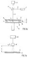
- the device for generating a test image a laser 1, the one directed Emits laser beam 2, and an XY scanner 3 in the form of a Galvanometer scanner, for deflecting the laser beam 2.
- a piezoelectrically controlled scanner is possible.
- a controller 4 is provided, which for the control of the scanner required data, for example Voltage curves generated.
- laser beam 2 is a for a wavelength of the laser light and / or a certain laser power sensitive film 5 for generating a test image provided, on which the deflected laser beam 2 strikes.
- photosensitive film 5 is, for example, thermal paper or UV-sensitive photo paper qeeiqnet. Film 5 defines one Working level of the scanner 3.
- the carrier 6 points to it height-adjustable side facing away from the film 5 or the laser beam 2 Feet 7, for example in the form of adjusting screws, by means of which the carrier 6 on the top 8a of a carrier platform 8 of a slide 9 in the rapid prototyping system is attachable.
- the support 6 is adjustable in height, that it has a defined distance h parallel to the top 8a of the carrier platform 8, so that it is also parallel to a surface extending over the slide Bath made of solidifiable material in the rapid prototyping system, which defines an image plane for the laser beam.
- the carrier 6 is together with the film 5 thereon removable from the slide 9 so that it can be removed and in the device for evaluating the test image can be introduced can.
- the device further comprises a Height-adjustable holder, not shown, for holding the carrier 6 with the film 5 arranged thereon, so that the film 5 has a distance d from the lens of the video camera.
- the video camera 10 is over the film loaded into the device 5 can be positioned in such a way that the entire working area can be viewed with the camera for generating image sections of one on the film 5 generated test image can be run.
- the carrier 6 by means of the height-adjustable feet 7 Use a spirit level to adjust it horizontally so that the carrier 6 parallel to the carrier platform 8 or parallel to the Bathroom surface is.
- the photosensitive film 5 is then placed or attached. Then, the photosensitive film 5 is made out of Fig. 2 can be seen by deflecting the laser beam 2 over the scanner 3 at predetermined positions on the film 5 for generation a test image 20 irradiated.
- the deflection of the laser beam 2 with the scanner 3 takes place at the beginning of the iteration based on an analytically generated correction table, which is the mapping between coordinates of in the Scanner arranged deflection mirrors and the actual coordinates, d. H. the points of incidence of the laser beam 2 on the working field indicates.
- the light-sensitive is preferably irradiated Films in the form of a test grid, which is a coordinate grid of actual coordinates. The center of the light sensitive Films 5 and thus the focus of the field is separated to generate a center coding marked.
- the test image is generated in a very short time, for example in 30 seconds or less. In that time is the probability for a significant laser or scanner drift very low. Therefore, a steady state of the laser and the Scanners held in the test image 20.
- the generated test image 20 is next examined in detail or scanned.
- the video camera 10 is successively Move over the generated test image 20 so that in each case Image sections 21 of the test image 20 are generated with the camera will.
- the size of the image sections 21 can be selected by the Lens of the video camera 10 can be determined.
- the use of a video camera 10 offers the advantage that accuracy by choosing a suitable lens can be improved because the resolution in digitization thereby being significantly increased.
- a Economic and mobile pixel scanners make every image section 21 scanned individually.
- Each image section 21 is in the computer 11 with a corresponding Image processing program analyzed. In doing so grid crossings of the test grid located in the image section 21 digitized on the basis of a gray value analysis and saved as image coordinates.
- the gray value analysis increases the resolution is considerable compared to a bare one Black and white analysis.
- the analysis allows the detection of Test images of different contrast, illumination and Format.
- the image coordinates can by the imaging properties the video camera 10 from the real coordinates that through the points of impact of the laser beam on the work field are defined.
- the size of the pixel scanner corresponding partial images digitized overlapping.
- those created with the image processing program Image coordinates of the grid points of the digitized Single images and their center point coding to an evaluation program to hand over.
- this evaluation program the digitized individual images put together to form an overall picture, the evaluation program being the center point coding recognizes the test pattern.
- the evaluation program being the center point coding recognizes the test pattern.
- a pixel scanner additionally generated position marks for evaluation and Composing the individual images used.
- the image coordinates of the generated are used for camera calibration
- Overall picture with the digitized coordinates, one photomechanical manufactured reference grid compared, one discrepancy between caused by the imaging of the camera Image coordinates and real coordinates recognized in the working plane is corrected so that the actual positions of the Laser beam in the overall image in real coordinates.
- the center point coding of the test image can be used for transformation be used.
- the evaluation of the overall picture will saved in a log.
- the correction table is modified.
- the evaluation program has a graphical user interface and is therefore easy to use.
- the program allows the analytical creation of the unmodified correction table with and without plan field correction.
- the program can be measured Points represent the point coordinates of the entire Assemble the test pattern regardless of the lattice constant and represent, output an evaluation log, the correction table Modify using the measurement data and correction tables display and usable for scanner control 4 save.
- the evaluation program is also in the Position, the measured height h of the distance of the carrier 6 to Top of the carrier platform 8 for generating a height correction to process for the correction table.
- the height correction is used to control the scanner in case the Calibration carried out in a rapid prototyping system in which the carrier 6 of the film 5 is not exactly in the plane positioned on the surface of the bath made of solidifiable material can be because e.g. the process medium or the solidifiable Material cannot be removed from there.
- the correction table modified with the evaluation program is then transfer to the scanner controller 4.
- a new Test patterns can be created, measured and evaluated with it. This evaluation can again be used to modify the correction table be used.
- the process takes one or two Iterations to a scanner system with real coordinates.
Landscapes
- Physics & Mathematics (AREA)
- Optics & Photonics (AREA)
- Engineering & Computer Science (AREA)
- Mechanical Engineering (AREA)
- Plasma & Fusion (AREA)
- Chemical & Material Sciences (AREA)
- Materials Engineering (AREA)
- General Physics & Mathematics (AREA)
- Manufacturing & Machinery (AREA)
- Length Measuring Devices By Optical Means (AREA)
- Mechanical Optical Scanning Systems (AREA)
Description
- Fig. 1a
- eine schematische Darstellung einer Vorrichtung zur Erzeugung eines Testbildes zur Durchführung des erfindungsgemäßen Verfahrens;
- Fig. 1b
- eine schematische Darstellung einer Vorrichtung zur Auswertung des Testbildes zur Durchführung des erfin-dungsgemäßen Verfahrens;
- Fig. 2
- eine schematische Darstellung des Verfahrensablaufs der Kalibrierung.
Claims (21)
- Verfahren zur Kalibrierung der Steuerung zur Ablenkung eines Laserstrahls für Rapid-Prototyping-Systeme mit den Schritten:a) Erzeugen eines Testbildes (20) durch Bestrahlen eines lichtempfindlichen Mediums (5) mit einem Laserstrahl (2) an vorgegebenen Sollpositionen in Abhängigkeit von Positionskoordinatenb) Erzeugen von digitalisierten Einzelbildern von Ausschnitten (21) des Testbildes (20)c) Zusammensetzen der digitalisierten Einzelbilder zu einem Gesamtbild des Testbildes (20)d) Vergleichen von Istpositionen des Laserstrahls (2) auf dem Gesamtbild mit den Positionskoordinatene) Berechnen und Bereitstellen von Korrekturdaten für die Steuerung (4) zur Ablenkung des Laserstrahls (2) auf der Grundlage der Vergleichsergebnisse.
- Verfahren nach Anspruch 1, dadurch gekennzeichnet, daß das Erzeugen der digitalisierten Einzelbilder jeweils durch Erzeugen eines Ausschnittes (21) des Testbildes (20) mit einer Bildaufnahmeeinrichtung (10) und anschließendes Digitalisieren des Ausschnittes (21) in einem Computer (11) erfolgt.
- Verfahren nach Anspruch 2, dadurch gekennzeichnet, daß als Bildaufnahmeeinrichtung eine positionierbare Videokamera (10) verwendet wird und die Positionierung der Videokamera (10) zum Erzeugen der Ausschnitte (21) des Testbildes (20) mittels eines Computers (11) gesteuert wird.
- Verfahren nach Anspruch 2, dadurch gekennzeichnet, daß als Bildaufnahmeeinrichtung ein positionierbarer Pixelscanner verwendet wird und die Positionierung des Pixelscanners zum Erzeugen der Ausschnitte (21) des Testbildes (20) mittels eines Computers (11) gesteuert wird.
- Verfahren nach Anspruch 2, dadurch gekennzeichnet, daß als Bildaufnahmeeinrichtung ein Pixelscanner verwendet wird.
- Verfahren nach einem der Ansprüche 1 bis 5, dadurch gekennzeichnet, daß als lichtempfindliches Medium ein für eine Wellenlänge des Laserstrahls (2) empfindlicher Film (5) verwendet wird.
- Verfahren nach einem der Ansprüche 1 bis 6, dadurch gekennzeichnet, daß als Testbild (20) ein Testgitter in Form eines Koordinatenrasters erzeugt wird.
- Verfahren nach einem der Ansprüche 1 bis 7, dadurch gekennzeichnet, daß auf dem Testbild (20) eine Mittelpunktkodierung erzeugt wird.
- Verfahren nach Anspruch 4 oder 5, dadurch gekennzeichnet, daß für das Erzeugen der digitalisierten Einzelbilder mit dem Pixelscanner Positioniermarken auf dem Testbild (20) erzeugt werden.
- Verfahren nach einem der Ansprüche 2 bis 9, dadurch gekennzeichnet, daß das Erzeugen der digitalisierten Einzelbilder auf der Grundlage einer Grauwertanalyse der mit der Bildaufnahmeeinrichtung erzeugten Ausschnitte (21) des Testbildes (20) im Computer (11) erfolgt.
- Verfahren nach einem der Ansprüche 1 bis 10, dadurch gekennzeichnet, daß eine Digitalisierung von Koordinaten des Testbildes (20) mittels eines Referenzgitters erfolgt.
- Verfahren nach Anspruch 11, dadurch gekennzeichnet, daß als Referenzgitter ein fotomechanisch erzeugtes Präzisionsreferenzgitter verwendet wird.
- Verfahren nach Anspruch 11 oder 12, dadurch gekennzeichnet, daß die Digitalisierung den Vergleich von Bildkoordinaten des Gesamtbildes mit Koordinaten des Referenzgitters und die Umrechnung der Bildkoordinaten in reale Koordinaten zum Erhalten der Istpositionen des Laserstrahles in dem Gesamtbild in realen Koordinaten auf der Grundlage des Vergleichs umfaßt.
- Verfahren nach einem der Ansprüche 6 bis 13, dadurch gekennzeichnet, daß der Film (5) auf eine auf einem Objektträger (8, 9) eines Rapid-Prototyping-Systems angebrachten und relativ zu dem Objektträger höhenverstellbaren Träger (6) aufgebracht wird.
- Verfahren nach einem der Ansprüche 1 bis 14, dadurch gekennzeichnet, daß die Erzeugung des Testbildes (20) und die Auswertung des Testbildes (20) räumlich getrennt voneinander erfolgen.
- Vorrichtung zur Durchführung des Verfahrens nach Anspruch 1 mitgekennzeichnet durcheinem Laser (1) zum Erzeugen eines gerichteten Laserstrahles (2);einer Steuerung (3, 4) zum Ablenken des Laserstrahls (2);einem lichtempfindlichen Medium (5) zum Belichten mit dem Laserstrahl (2) zum Erzeugen eines Testbildes (20),eine positionierbare Bildaufnahmeeinrichtung (10) und einen Computer (11) zumErzeugen von digitalisierten Einzelbildern von Ausschnitten (21) des Testbildes (20),Zusammensetzen der digitalisierten Einzelbilder zu einem Gesamtbild des Testbildes (20),Vergleichen von Istpositionen des Laserstrahls (2) auf dem Gesamtbild mit den Positionskoordinaten undBerechnen und Bereitstellen von Korrekturdaten für die Steuerung (4) zur Ablenkung des Laserstrahls (2) auf der Grundlage der Vergleichsergebnisse.
- Vorrichtung nach Anspruch 16, dadurch gekennzeichnet, daß die Steuerung zum Ablenken des Laserstrahls (2) einen Galvanometerscanner (3) und eine Galvanometersteuerung (4) umfaßt.
- Vorrichtung nach Anspruch 16 oder 17, gekennzeichnet durch einen Träger (6) zum Tragen des lichtempfindlichen Mediums (5).
- Vorrichtung nach Anspruch 18, dadurch gekennzeichnet, daß der Träger (6) auf einem Objektträger (8, 9) einem Rapid-Prototyping-System anbringbar ist und relativ zu diesem in einer Richtung des Laserstrahles (2) höhenverstellbar ist.
- Vorrichtung nach einem der Ansprüche 16 bis 19, dadurch gekennzeichnet, daß die Bildaufnahmeeinrichtung als Videokamera (10) ausgebildet ist.
- Vorrichtung nach einem der Ansprüche 16 bis 19, dadurch gekennzeichnet, daß die Bildaufnahmeeinrichtung als Pixelscanner ausgebildet ist.
Applications Claiming Priority (3)
| Application Number | Priority Date | Filing Date | Title |
|---|---|---|---|
| DE4437284 | 1994-10-18 | ||
| DE4437284A DE4437284A1 (de) | 1994-10-18 | 1994-10-18 | Verfahren zum Kalibrieren einer Steuerung zur Ablenkung eines Laserstrahls |
| PCT/EP1995/003724 WO1996012217A1 (de) | 1994-10-18 | 1995-09-21 | Verfahren und vorrichtung zum kalibrieren einer steuerung zur ablenkung eines laserstrahls |
Publications (2)
| Publication Number | Publication Date |
|---|---|
| EP0792481A1 EP0792481A1 (de) | 1997-09-03 |
| EP0792481B1 true EP0792481B1 (de) | 1998-06-03 |
Family
ID=6531118
Family Applications (1)
| Application Number | Title | Priority Date | Filing Date |
|---|---|---|---|
| EP95932781A Expired - Lifetime EP0792481B1 (de) | 1994-10-18 | 1995-09-21 | Verfahren und vorrichtung zum kalibrieren einer steuerung zur ablenkung eines laserstrahls |
Country Status (5)
| Country | Link |
|---|---|
| US (1) | US5832415A (de) |
| EP (1) | EP0792481B1 (de) |
| JP (1) | JP2979431B2 (de) |
| DE (2) | DE4437284A1 (de) |
| WO (1) | WO1996012217A1 (de) |
Cited By (9)
| Publication number | Priority date | Publication date | Assignee | Title |
|---|---|---|---|---|
| DE19918613A1 (de) * | 1999-04-23 | 2000-11-30 | Eos Electro Optical Syst | Verfahren zur Kalibrierung einer Vorrichtung zum Herstellen eines dreidimensionalen Objektes, Kalibrierungsvorrichtung und Verfahren und Vorrichtung zur Herstellung eines dreidimensionalen Objektes |
| DE102009016585A1 (de) | 2009-04-06 | 2010-10-07 | Eos Gmbh Electro Optical Systems | Verfahren und Vorrichtung zum Kalibrieren einer Bestrahlungsvorrichtung |
| DE102013208651A1 (de) * | 2013-05-10 | 2014-11-13 | Eos Gmbh Electro Optical Systems | Verfahren zum automatischen Kalibrieren einer Vorrichtung zum generativen Herstellen eines dreidimensionalen Objekts |
| DE102014014888A1 (de) * | 2014-10-13 | 2016-04-14 | Cl Schutzrechtsverwaltungs Gmbh | Verfahren zur Einrichtung und Justierung einer Bauplatte |
| DE102016001355A1 (de) | 2016-02-08 | 2017-08-10 | Primes GmbH Meßtechnik für die Produktion mit Laserstrahlung | Analyse von Laserstrahlen in Anlagen für generative Fertigung |
| CN110239091A (zh) * | 2014-08-22 | 2019-09-17 | Cl产权管理有限公司 | 用于制造三维物体的装置和方法 |
| US10974457B2 (en) | 2016-05-04 | 2021-04-13 | SLM Solutions Group AG | Device and method for calibrating an irradiation system of an apparatus for producing a three-dimensional work piece |
| DE102022129042B3 (de) | 2022-11-03 | 2023-09-21 | additiveStream4D GmbH | Kalibriersystem und Kalibrierverfahren zur Kalibrierung eines Bauplattformsystems in einer additiven Fertigungsvorrichtung |
| WO2024094256A1 (de) | 2022-11-03 | 2024-05-10 | additiveStream4D GmbH | Kalibriersystem und kalibrierverfahren zur kalibrierung eines bauplattformsystems in einer additiven fertigungsvorrichtung |
Families Citing this family (108)
| Publication number | Priority date | Publication date | Assignee | Title |
|---|---|---|---|---|
| JP3526385B2 (ja) * | 1997-03-11 | 2004-05-10 | 株式会社東芝 | パターン形成装置 |
| DE19732668C2 (de) * | 1997-07-29 | 1999-10-28 | Scaps Gmbh | Vorrichtung und Verfahren zur Kalibrierung von Strahlabtastvorrichtungen |
| JP3745225B2 (ja) * | 1997-12-26 | 2006-02-15 | 三菱電機株式会社 | レーザ加工装置 |
| DE19831340C1 (de) * | 1998-07-13 | 2000-03-02 | Siemens Ag | Verfahren und Anordnung zum Kalibrieren einer Laserbearbeitungsmaschine zum Bearbeiten von Werkstücken |
| US6332032B1 (en) * | 1998-12-03 | 2001-12-18 | The United States Of America As Represented By The Secretary Of The Army | Method for generating test files from scanned test vector pattern drawings |
| JP2002542042A (ja) * | 1999-04-27 | 2002-12-10 | ジーエスアイ ルモニクス インコーポレイテッド | レーザ校正装置及び方法 |
| US7444616B2 (en) * | 1999-05-20 | 2008-10-28 | Micronic Laser Systems Ab | Method for error reduction in lithography |
| US6712856B1 (en) | 2000-03-17 | 2004-03-30 | Kinamed, Inc. | Custom replacement device for resurfacing a femur and method of making the same |
| US6456751B1 (en) | 2000-04-13 | 2002-09-24 | Calient Networks, Inc. | Feedback stabilization of a loss optimized switch |
| DE10020604C1 (de) * | 2000-04-27 | 2001-07-26 | Teschauer & Petsch Ag Dr | Verfahren zum Kalibrieren von Galvanometersteuerungen und Vorrichtung zur Durchführung des Verfahrens |
| US6728016B1 (en) | 2000-06-05 | 2004-04-27 | Calient Networks, Inc. | Safe procedure for moving mirrors in an optical cross-connect switch |
| US6587611B1 (en) | 2000-06-06 | 2003-07-01 | Calient Networks, Inc. | Maintaining path integrity in an optical switch |
| JP3446741B2 (ja) * | 2001-01-24 | 2003-09-16 | 松下電工株式会社 | 光ビームの偏向制御方法及び光造形装置 |
| DE10131610C1 (de) * | 2001-06-29 | 2003-02-20 | Siemens Dematic Ag | Verfahren zur Kalibrierung des optischen Systems einer Lasermaschine zur Bearbeitung von elektrischen Schaltungssubstraten |
| JP3531629B2 (ja) * | 2001-07-26 | 2004-05-31 | 松下電工株式会社 | 光造形システムにおけるレーザビームの偏向制御方法 |
| DE10150129C1 (de) * | 2001-10-11 | 2003-04-17 | Siemens Ag | Verfahren zum Kalibrieren einer Laserbearbeitungsmaschine, Kalibriereinrichtung für Laserbearbeitungsmaschinen sowie Substrathalter für eine Laserbearbeitungsmaschine |
| DE10157983C5 (de) * | 2001-11-27 | 2008-05-08 | Fraunhofer-Gesellschaft zur Förderung der angewandten Forschung e.V. | Positionier- und/oder Laserbearbeitungsverfahren und Vorrichtung |
| US6836740B2 (en) | 2002-01-31 | 2004-12-28 | Heidelberger Druckmaschinen Ag | Method for determining the relative position of first and second imaging devices, method of correcting a position of a point of projection of the devices, printing form exposer, printing unit, printing unit group and printing press |
| DE10206183A1 (de) * | 2002-02-14 | 2003-08-28 | Siemens Ag | Verfahren zur Bestimmung der Genauigkeit von Bearbeitungsmaschine |
| DE10340382B4 (de) * | 2002-09-30 | 2012-10-31 | Heidelberger Druckmaschinen Ag | Verfahren zur Bestimmung des Abstandes von Projektionspunkten auf der Oberfläche einer Druckform |
| DE102006055053A1 (de) * | 2006-11-22 | 2008-05-29 | Eos Gmbh Electro Optical Systems | Vorrichtung zum schichtweisen Herstellen eines dreidimensionalen Objekts |
| DE102006055050A1 (de) * | 2006-11-22 | 2008-05-29 | Eos Gmbh Electro Optical Systems | Vorrichtung zum schichtweisen Herstellen eines dreidimensionalen Objekts und Verfahren zum Justieren eines Optiksystems von dieser |
| DE102006055075A1 (de) | 2006-11-22 | 2008-05-29 | Eos Gmbh Electro Optical Systems | Vorrichtung zum schichtweisen Herstellen eines dreidimensionalen Objekts |
| US8154572B2 (en) | 2007-05-31 | 2012-04-10 | Eastman Kodak Company | Adjusting the calibration of an imaging system |
| JP5116379B2 (ja) * | 2007-07-02 | 2013-01-09 | 株式会社キーエンス | レーザ加工装置並びにその設定方法及び設定プログラム |
| WO2009018857A1 (en) * | 2007-08-06 | 2009-02-12 | Stephen Hastings | Method for reactive optical correction of galvano motor scanning heads |
| WO2009026520A1 (en) * | 2007-08-23 | 2009-02-26 | 3D Systems, Inc. | Automatic geometric calibration using laser scanning reflectometry |
| SG152090A1 (en) * | 2007-10-23 | 2009-05-29 | Hypertronics Pte Ltd | Scan head calibration system and method |
| GB0816308D0 (en) | 2008-09-05 | 2008-10-15 | Mtt Technologies Ltd | Optical module |
| WO2011019669A1 (en) * | 2009-08-09 | 2011-02-17 | Rolls-Royce Corporation | Method and apparatus for calibrating a projected image manufacturing device |
| KR101094313B1 (ko) | 2009-08-19 | 2011-12-19 | 대우조선해양 주식회사 | 로봇 tcp와 lvs 사이의 캘리브레이션 방법 및 캘리브레이션 지그 |
| TWI438050B (zh) * | 2011-12-16 | 2014-05-21 | Ind Tech Res Inst | 雷射加工誤差校正方法及處理器 |
| CN103894740A (zh) * | 2012-12-31 | 2014-07-02 | 徐州润物科技发展有限公司 | 汽车内饰生产用机器人 |
| CN105163930B (zh) | 2013-03-15 | 2017-12-12 | 3D系统公司 | 用于激光烧结系统的滑道 |
| GB201317974D0 (en) * | 2013-09-19 | 2013-11-27 | Materialise Nv | System and method for calibrating a laser scanning system |
| US10618131B2 (en) | 2014-06-05 | 2020-04-14 | Nlight, Inc. | Laser patterning skew correction |
| CN104191094A (zh) * | 2014-06-12 | 2014-12-10 | 上海功源自动化技术有限公司 | 高精度晶圆背刻对中系统沟槽对位方法 |
| US9403235B2 (en) | 2014-06-20 | 2016-08-02 | Velo3D, Inc. | Apparatuses, systems and methods for three-dimensional printing |
| TWI526797B (zh) * | 2014-09-02 | 2016-03-21 | 三緯國際立體列印科技股份有限公司 | 立體列印裝置的校正裝置以及校正方法 |
| TW201617202A (zh) * | 2014-11-12 | 2016-05-16 | 鈺創科技股份有限公司 | 具有調整功能的立體印表機及其操作方法 |
| EP3461622A1 (de) | 2014-11-24 | 2019-04-03 | Additive Industries B.V. | Vorrichtung und verfahren zur herstellung eines objekts mittels generativer fertigung |
| US9837783B2 (en) | 2015-01-26 | 2017-12-05 | Nlight, Inc. | High-power, single-mode fiber sources |
| US9787871B2 (en) * | 2015-01-29 | 2017-10-10 | Xerox Corporation | Hidden Markov model generation of multi-plane random screens |
| US10050404B2 (en) | 2015-03-26 | 2018-08-14 | Nlight, Inc. | Fiber source with cascaded gain stages and/or multimode delivery fiber with low splice loss |
| WO2017008022A1 (en) | 2015-07-08 | 2017-01-12 | Nlight, Inc. | Fiber with depressed central index for increased beam parameter product |
| CN106363621B (zh) * | 2015-07-21 | 2019-01-04 | 南京中科川思特软件科技有限公司 | 一种机器人激光切割全路径的生成方法 |
| US9676145B2 (en) | 2015-11-06 | 2017-06-13 | Velo3D, Inc. | Adept three-dimensional printing |
| JP2019504182A (ja) | 2015-11-16 | 2019-02-14 | レニショウ パブリック リミテッド カンパニーRenishaw Public Limited Company | アディティブ製造装置のためのモジュールおよび方法 |
| US10434600B2 (en) | 2015-11-23 | 2019-10-08 | Nlight, Inc. | Fine-scale temporal control for laser material processing |
| US11179807B2 (en) | 2015-11-23 | 2021-11-23 | Nlight, Inc. | Fine-scale temporal control for laser material processing |
| JP2017100309A (ja) * | 2015-11-30 | 2017-06-08 | 株式会社エイチ・ティー・エル | 3次元造形方法 |
| CN108698126A (zh) | 2015-12-10 | 2018-10-23 | 维洛3D公司 | 精湛的三维打印 |
| DE102015226722A1 (de) * | 2015-12-23 | 2017-06-29 | Eos Gmbh Electro Optical Systems | Vorrichtung und Verfahren zum Kalibrieren einer Vorrichtung zum generativen Herstellen eines dreidimensionalen Objekts |
| WO2017127573A1 (en) | 2016-01-19 | 2017-07-27 | Nlight, Inc. | Method of processing calibration data in 3d laser scanner systems |
| JP6979963B2 (ja) | 2016-02-18 | 2021-12-15 | ヴェロ・スリー・ディー・インコーポレイテッド | 正確な3次元印刷 |
| DE102016106403A1 (de) * | 2016-04-07 | 2017-10-12 | Cl Schutzrechtsverwaltungs Gmbh | Verfahren zur Kalibrierung wenigstens eines Scannsystems, einer SLS- oder SLM-Anlage |
| EP3448604B1 (de) | 2016-04-25 | 2023-10-25 | Renishaw PLC | Verfahren zur kalibration von scannern in einem generativen herstellungsgerät |
| US11691343B2 (en) | 2016-06-29 | 2023-07-04 | Velo3D, Inc. | Three-dimensional printing and three-dimensional printers |
| EP3263316B1 (de) | 2016-06-29 | 2019-02-13 | VELO3D, Inc. | Dreidimensionales drucken und dreidimensionaler drucken |
| US10673197B2 (en) | 2016-09-29 | 2020-06-02 | Nlight, Inc. | Fiber-based optical modulator |
| US10730785B2 (en) | 2016-09-29 | 2020-08-04 | Nlight, Inc. | Optical fiber bending mechanisms |
| US10673198B2 (en) | 2016-09-29 | 2020-06-02 | Nlight, Inc. | Fiber-coupled laser with time varying beam characteristics |
| US10423015B2 (en) | 2016-09-29 | 2019-09-24 | Nlight, Inc. | Adjustable beam characteristics |
| US10673199B2 (en) | 2016-09-29 | 2020-06-02 | Nlight, Inc. | Fiber-based saturable absorber |
| US20180093418A1 (en) | 2016-09-30 | 2018-04-05 | Velo3D, Inc. | Three-dimensional objects and their formation |
| US20180126460A1 (en) | 2016-11-07 | 2018-05-10 | Velo3D, Inc. | Gas flow in three-dimensional printing |
| JP6177412B1 (ja) * | 2016-11-22 | 2017-08-09 | 株式会社ソディック | 積層造形装置 |
| US20180186082A1 (en) | 2017-01-05 | 2018-07-05 | Velo3D, Inc. | Optics in three-dimensional printing |
| US10145672B2 (en) * | 2017-01-24 | 2018-12-04 | Lithoptek LLC | Detection of position, orientation and scale of work pieces using retroreflective surfaces |
| US10369629B2 (en) | 2017-03-02 | 2019-08-06 | Veo3D, Inc. | Three-dimensional printing of three-dimensional objects |
| US20180281284A1 (en) | 2017-03-28 | 2018-10-04 | Velo3D, Inc. | Material manipulation in three-dimensional printing |
| JP6809965B2 (ja) * | 2017-03-30 | 2021-01-06 | 三菱パワー株式会社 | 3次元積層造形条件決定方法、3次元積層造形条件決定装置、3次元積層造形実行方法および3次元積層造形装置 |
| EP3607389B1 (de) | 2017-04-04 | 2023-06-07 | Nlight, Inc. | Optische referenzerzeugung für die kalibrierung von galvanometrischen scannern |
| US11389896B2 (en) | 2017-04-04 | 2022-07-19 | Nlight, Inc. | Calibration test piece for galvanometric laser calibration |
| FR3067623B1 (fr) | 2017-06-19 | 2021-04-30 | Addup | Calibration de la focalisation d'une source de rayonnement de puissance d'un appareil de fabrication additive |
| FR3067624B1 (fr) * | 2017-06-19 | 2021-12-17 | Addup | Calibration d'un systeme de tete d'une source de rayonnement de puissance d'un appareil de fabrication additive |
| CN109109318A (zh) * | 2017-06-26 | 2019-01-01 | 三纬国际立体列印科技股份有限公司 | 多光源调校装置及其使用方法 |
| CN107248375A (zh) * | 2017-07-20 | 2017-10-13 | 武汉华星光电半导体显示技术有限公司 | 用于刻号机的识别号补值方法及系统 |
| EP3447440A1 (de) * | 2017-08-25 | 2019-02-27 | CL Schutzrechtsverwaltungs GmbH | Tragbare messeinheit |
| US10272525B1 (en) | 2017-12-27 | 2019-04-30 | Velo3D, Inc. | Three-dimensional printing systems and methods of their use |
| US10144176B1 (en) | 2018-01-15 | 2018-12-04 | Velo3D, Inc. | Three-dimensional printing systems and methods of their use |
| CN109015637A (zh) * | 2018-08-13 | 2018-12-18 | 广州瑞松北斗汽车装备有限公司 | 汽车制造生产线视觉引导上料方法 |
| EP3659726B1 (de) * | 2018-11-27 | 2023-01-11 | Additive Industries B.V. | Verfahren zur kalibrierung einer vorrichtung zur herstellung eines objekts durch generative fertigung und vorrichtung für das verfahren |
| US10919111B2 (en) | 2018-12-05 | 2021-02-16 | Robert Bosch Tool Corporation | Laser engraver mirror adjustment system |
| EP3914417A1 (de) * | 2019-01-23 | 2021-12-01 | nLIGHT, Inc. | Galvanometrisches lasersystem mit einem kalibriertestteil |
| US11679551B2 (en) | 2019-02-28 | 2023-06-20 | General Electric Company | Compensating laser alignment for irregularities in an additive manufacturing machine powderbed |
| US11579440B2 (en) | 2019-03-14 | 2023-02-14 | Nlight, Inc. | Focus assessment in dynamically focused laser system |
| US11525968B2 (en) | 2019-03-14 | 2022-12-13 | Nlight, Inc. | Calibration validation using geometric features in galvanometric scanning systems |
| US12290878B2 (en) | 2019-03-20 | 2025-05-06 | Bobst Mex Sa | Characterization method and system for a laser processing machine with a moving sheet or web |
| JP7130596B2 (ja) * | 2019-05-21 | 2022-09-05 | 株式会社荏原製作所 | 造形物を製造するためのam装置およびam装置におけるビームの照射位置を試験する方法 |
| EP4003701A4 (de) | 2019-07-26 | 2023-11-08 | Velo3d Inc. | Qualitätssicherung bei der herstellung von dreidimensionalen objekten |
| US11084123B2 (en) * | 2019-09-05 | 2021-08-10 | The Boeing Company | Laser-etching and machine-vision positioning system |
| EP3795336B1 (de) * | 2019-09-19 | 2022-07-13 | LayerWise NV | Kalibrierungsverfahren für ein pulverfusionssystem |
| US11260600B2 (en) | 2019-10-31 | 2022-03-01 | Concept Laser Gmbh | Method for calibrating an irradiation device for an apparatus for additively manufacturing three-dimensional objects |
| DE102020200599A1 (de) | 2020-01-20 | 2021-07-22 | Fraunhofer-Gesellschaft zur Förderung der angewandten Forschung e.V. | Verfahren und Vorrichtung zur Steigerung der Fertigungsgenauigkeit beim pulverbettbasierten Strahlschmelzen mit einem verfahrbaren Bearbeitungskopf |
| GB202010315D0 (en) | 2020-07-06 | 2020-08-19 | Renishaw Plc | Improvements in or relating to an optical scanner for directing electromagnetic radiation to different locations within a sacn field |
| CN112170836B (zh) * | 2020-08-11 | 2022-09-09 | 西安铂力特增材技术股份有限公司 | 一种3d打印设备自动嫁接打印的方法 |
| JP7213220B2 (ja) * | 2020-11-17 | 2023-01-26 | 株式会社ソディック | 積層造形装置の較正方法 |
| JP7041238B1 (ja) | 2020-12-07 | 2022-03-23 | 株式会社ソディック | 積層造形装置の較正方法及び積層造形装置 |
| DE102021103493C5 (de) | 2021-02-15 | 2024-08-22 | Novanta Europe Gmbh | Verfahren für eine Scanfeldkorrektur mindestens einer Laserscannervorrichtung, Laserscannervorrichtung, Streumusterelement, Streumusterhaltevorrichtung und Scanfeldkorrektursystem |
| US12309327B2 (en) | 2021-02-24 | 2025-05-20 | General Electric Company | Automated beam scan calibration, alignment, and adjustment |
| US12097558B2 (en) | 2021-04-27 | 2024-09-24 | General Electric Company | Systems and methods for laser processing system characterization and calibration |
| EP4227036B1 (de) * | 2022-02-09 | 2025-04-02 | Raylase GmbH | Laserkalibirierungssystem,laserbearbeitungssystem und verfahren zum automatische kalibrierung eines laserbearbeitungssystems unter verwendung eines nicht-integrierten telezentrischen optischen detektors mit begrenzten freiheitsgraden |
| AT526197B1 (de) | 2022-06-09 | 2024-10-15 | Trotec Laser Gmbh | Verfahren zum Ermitteln von, insbesondere statischen, Geometriefehlern einer Lasermaschine zum Schneiden, Gravieren, Markieren und/oder Beschriften eines Werkstückes und ein Verfahren zum Ermitteln der Lage bzw. Position des Mittelpunkts eines Detektors am Detektorelement sowie Kalibrier-Segment und Lasermaschine hierfür |
| NL2033096B1 (en) | 2022-09-21 | 2024-03-26 | Additive Ind Bv | An apparatus for producing an object by means of additive manufacturing and a method of calibrating the apparatus |
| CN115815791B (zh) * | 2023-02-17 | 2023-04-21 | 北京金橙子科技股份有限公司 | 实现激光束焦点自动居中的校准方法 |
| EP4506096A3 (de) * | 2023-08-07 | 2025-05-14 | Precitec GmbH & Co. KG | Verfahren zum kalibrieren eines laserbearbeitungssystems sowie laserbearbeitungssystem zur durchführung des verfahrens |
| DE102023126059A1 (de) * | 2023-09-26 | 2025-03-27 | TRUMPF Werkzeugmaschinen SE + Co. KG | Wartungsverfahren sowie Wartungssystem für eine Laserstrahloptik |
Family Cites Families (13)
| Publication number | Priority date | Publication date | Assignee | Title |
|---|---|---|---|---|
| DE3030922A1 (de) * | 1980-08-16 | 1982-05-13 | Messer Griesheim Gmbh, 6000 Frankfurt | Einrichtung zur erstellung eines steuerlochstreifens fuer werkzeugmaschinen, insbesondere brennschneidmaschinen |
| US4453085A (en) * | 1981-05-11 | 1984-06-05 | Diffracto Ltd. | Electro-optical systems for control of robots, manipulator arms and co-ordinate measuring machines |
| US4585342A (en) * | 1984-06-29 | 1986-04-29 | International Business Machines Corporation | System for real-time monitoring the characteristics, variations and alignment errors of lithography structures |
| DE4005985C1 (en) * | 1990-02-26 | 1991-06-20 | Webasto Ag Fahrzeugtechnik, 8035 Stockdorf, De | Sliding roof for motor vehicle - has sliding panel with edge proofing fitting into frame in vehicle roof |
| JPH04189200A (ja) * | 1990-11-22 | 1992-07-07 | Nissha Printing Co Ltd | 凹凸転写箔 |
| DE4112695C3 (de) * | 1990-12-21 | 1998-07-23 | Eos Electro Optical Syst | Verfahren und Vorrichtung zum Herstellen eines dreidimensionalen Objekts |
| US5460758A (en) * | 1990-12-21 | 1995-10-24 | Eos Gmbh Electro Optical Systems | Method and apparatus for production of a three-dimensional object |
| DE4134265C2 (de) * | 1991-10-16 | 1993-11-25 | Eos Electro Optical Syst | Vorrichtung und Verfahren zur Herstellung eines dreidimensionalen Objekts mittels Stereographie |
| JPH0634349A (ja) * | 1992-07-16 | 1994-02-08 | Kobe Steel Ltd | 逆反射スクリーンによる表面検査方法 |
| DE4227817C2 (de) * | 1992-08-21 | 1997-11-27 | Eos Electro Optical Syst | Mehrfach-Meßsystem für Oberflächen |
| FR2696969B1 (fr) * | 1992-10-21 | 1995-01-06 | Univ Joseph Fourier | Procédé d'étalonnage d'un robot. |
| US5430666A (en) * | 1992-12-18 | 1995-07-04 | Dtm Corporation | Automated method and apparatus for calibration of laser scanning in a selective laser sintering apparatus |
| DE4300478C2 (de) * | 1993-01-11 | 1998-05-20 | Eos Electro Optical Syst | Verfahren und Vorrichtung zum Herstellen eines dreidimensionalen Objekts |
-
1994
- 1994-10-18 DE DE4437284A patent/DE4437284A1/de not_active Ceased
-
1995
- 1995-09-21 EP EP95932781A patent/EP0792481B1/de not_active Expired - Lifetime
- 1995-09-21 US US08/817,991 patent/US5832415A/en not_active Expired - Lifetime
- 1995-09-21 WO PCT/EP1995/003724 patent/WO1996012217A1/de active IP Right Grant
- 1995-09-21 JP JP8512878A patent/JP2979431B2/ja not_active Expired - Fee Related
- 1995-09-21 DE DE59502439T patent/DE59502439D1/de not_active Expired - Lifetime
Cited By (14)
| Publication number | Priority date | Publication date | Assignee | Title |
|---|---|---|---|---|
| DE19918613A1 (de) * | 1999-04-23 | 2000-11-30 | Eos Electro Optical Syst | Verfahren zur Kalibrierung einer Vorrichtung zum Herstellen eines dreidimensionalen Objektes, Kalibrierungsvorrichtung und Verfahren und Vorrichtung zur Herstellung eines dreidimensionalen Objektes |
| DE102009016585A1 (de) | 2009-04-06 | 2010-10-07 | Eos Gmbh Electro Optical Systems | Verfahren und Vorrichtung zum Kalibrieren einer Bestrahlungsvorrichtung |
| WO2010115588A2 (de) | 2009-04-06 | 2010-10-14 | Eos Gmbh Electro Optical Systems | Verfahren und vorrichtung zum kalibrieren einer bestrahlungsvorrichtung |
| US10336008B2 (en) | 2013-05-10 | 2019-07-02 | Eos Gmbh Electro Optical Systems | Method for automatic calibration of a device for generative production of a three-dimensional object |
| DE102013208651A1 (de) * | 2013-05-10 | 2014-11-13 | Eos Gmbh Electro Optical Systems | Verfahren zum automatischen Kalibrieren einer Vorrichtung zum generativen Herstellen eines dreidimensionalen Objekts |
| CN110239091A (zh) * | 2014-08-22 | 2019-09-17 | Cl产权管理有限公司 | 用于制造三维物体的装置和方法 |
| DE102014014888A1 (de) * | 2014-10-13 | 2016-04-14 | Cl Schutzrechtsverwaltungs Gmbh | Verfahren zur Einrichtung und Justierung einer Bauplatte |
| WO2017137022A1 (de) | 2016-02-08 | 2017-08-17 | Primes Gmbh | Analyse von laserstrahlen in anlagen für generative fertigung |
| DE102016001355A1 (de) | 2016-02-08 | 2017-08-10 | Primes GmbH Meßtechnik für die Produktion mit Laserstrahlung | Analyse von Laserstrahlen in Anlagen für generative Fertigung |
| DE102016001355B4 (de) | 2016-02-08 | 2022-03-24 | Primes GmbH Meßtechnik für die Produktion mit Laserstrahlung | Verfahren und Vorrichtung zur Analyse von Laserstrahlen in Anlagen für generative Fertigung |
| US11911852B2 (en) | 2016-02-08 | 2024-02-27 | Primes GmbH Meßtechnik für die Produktion mit Laserstrahlung | Analysis of laser beams in systems for a generative manufacturing process |
| US10974457B2 (en) | 2016-05-04 | 2021-04-13 | SLM Solutions Group AG | Device and method for calibrating an irradiation system of an apparatus for producing a three-dimensional work piece |
| DE102022129042B3 (de) | 2022-11-03 | 2023-09-21 | additiveStream4D GmbH | Kalibriersystem und Kalibrierverfahren zur Kalibrierung eines Bauplattformsystems in einer additiven Fertigungsvorrichtung |
| WO2024094256A1 (de) | 2022-11-03 | 2024-05-10 | additiveStream4D GmbH | Kalibriersystem und kalibrierverfahren zur kalibrierung eines bauplattformsystems in einer additiven fertigungsvorrichtung |
Also Published As
| Publication number | Publication date |
|---|---|
| DE59502439D1 (de) | 1998-07-09 |
| EP0792481A1 (de) | 1997-09-03 |
| DE4437284A1 (de) | 1996-04-25 |
| JPH09511854A (ja) | 1997-11-25 |
| JP2979431B2 (ja) | 1999-11-15 |
| US5832415A (en) | 1998-11-03 |
| WO1996012217A1 (de) | 1996-04-25 |
Similar Documents
| Publication | Publication Date | Title |
|---|---|---|
| EP0792481B1 (de) | Verfahren und vorrichtung zum kalibrieren einer steuerung zur ablenkung eines laserstrahls | |
| EP3362262B1 (de) | Verfahren und beschichter für eine vorrichtung zum herstellen eines dreidimensionalen objekts | |
| CN107708971B (zh) | 用于校准sls系统或slm系统的至少一个扫描系统的方法 | |
| DE60215852T2 (de) | Defekt-pixel-kompensationsverfahren | |
| DE69226217T2 (de) | Projektionsbelichtungsvorrichtung | |
| US4918284A (en) | Calibrating laser trimming apparatus | |
| US6483596B1 (en) | Method of calibrating an apparatus for producing a three-dimensional object, calibration apparatus and method and apparatus for producing a three-dimensional object | |
| DE19721688B4 (de) | Oberflächenerfassungseinrichtung und Verfahren zur Oberflächenerfassung | |
| DE69023186T2 (de) | Belichtungsvorrichtung. | |
| DE102013215040B4 (de) | Kompakte Vorrichtung zur Herstellung eines dreidimensionalen Objekts durch Verfestigen eines fotohärtenden Materials | |
| EP1974848B1 (de) | System und zugehöriges Verfahren zum Korrigieren einer Laserstrahlablenkeinheit | |
| DE2516390A1 (de) | Verfahren und vorrichtung zum herstellen mikrominiaturisierter bauelemente | |
| EP1401609A1 (de) | Verfahren zur kalibrierung des optischen systems einer lasermaschine zur bearbeitung von elektrischen schaltungssubstraten | |
| DE112008002862T5 (de) | Abtastkopfkalibrierungssystem und Verfahren | |
| DE10392578T5 (de) | System und Verfahren zur Herstellung von gedruckten Schaltungsplatinen unter Verwendung von nichtgleichmässig modifizierten Bildern | |
| WO2020249460A1 (de) | Vorrichtung und verfahren zur referenzierung und kalibrierung einer laseranlage | |
| DE202013103446U1 (de) | Kompakte Vorrichtung zur Herstellung eines dreidimensionalen Objekts durch Verfestigen eines fotohärtenden Materials | |
| DE10296416T5 (de) | Verfahren und Vorrichtung zur Registrierungssteuerung in der Produktion durch Belichten | |
| DE102017210994A1 (de) | Messsystem für eine Vorrichtung zum generativen Herstellen eines dreidimensionalen Objekts | |
| DE102007036850B4 (de) | Verfahren zur Korrektur von Nichtlinearitäten der Interferometer einer Koordinaten-Messmaschine | |
| DE4305183A1 (de) | ||
| DE69527682T2 (de) | Belichtungsapparat und Belichtungsverfahren | |
| DD219567A5 (de) | Verfahren und geraet fuer die fehlerpruefung von uebertragungsmasken von leitungsmustern integrierter schaltungen | |
| DE19948797C2 (de) | Substrathalter und Verwendung des Substrathalters in einem hochgenauen Messgerät | |
| DE68928485T2 (de) | Profilierung eines Strahlungsbündels für Stereolithographie |
Legal Events
| Date | Code | Title | Description |
|---|---|---|---|
| PUAI | Public reference made under article 153(3) epc to a published international application that has entered the european phase |
Free format text: ORIGINAL CODE: 0009012 |
|
| 17P | Request for examination filed |
Effective date: 19970312 |
|
| AK | Designated contracting states |
Kind code of ref document: A1 Designated state(s): DE FR GB IT |
|
| GRAG | Despatch of communication of intention to grant |
Free format text: ORIGINAL CODE: EPIDOS AGRA |
|
| GRAG | Despatch of communication of intention to grant |
Free format text: ORIGINAL CODE: EPIDOS AGRA |
|
| 17Q | First examination report despatched |
Effective date: 19970916 |
|
| GRAG | Despatch of communication of intention to grant |
Free format text: ORIGINAL CODE: EPIDOS AGRA |
|
| GRAG | Despatch of communication of intention to grant |
Free format text: ORIGINAL CODE: EPIDOS AGRA |
|
| GRAH | Despatch of communication of intention to grant a patent |
Free format text: ORIGINAL CODE: EPIDOS IGRA |
|
| GRAH | Despatch of communication of intention to grant a patent |
Free format text: ORIGINAL CODE: EPIDOS IGRA |
|
| GRAA | (expected) grant |
Free format text: ORIGINAL CODE: 0009210 |
|
| AK | Designated contracting states |
Kind code of ref document: B1 Designated state(s): DE FR GB IT |
|
| REF | Corresponds to: |
Ref document number: 59502439 Country of ref document: DE Date of ref document: 19980709 |
|
| ET | Fr: translation filed | ||
| GBT | Gb: translation of ep patent filed (gb section 77(6)(a)/1977) |
Effective date: 19980626 |
|
| ITF | It: translation for a ep patent filed | ||
| PLBE | No opposition filed within time limit |
Free format text: ORIGINAL CODE: 0009261 |
|
| STAA | Information on the status of an ep patent application or granted ep patent |
Free format text: STATUS: NO OPPOSITION FILED WITHIN TIME LIMIT |
|
| 26N | No opposition filed | ||
| REG | Reference to a national code |
Ref country code: GB Ref legal event code: IF02 |
|
| PGFP | Annual fee paid to national office [announced via postgrant information from national office to epo] |
Ref country code: DE Payment date: 20130919 Year of fee payment: 19 |
|
| PGFP | Annual fee paid to national office [announced via postgrant information from national office to epo] |
Ref country code: FR Payment date: 20130919 Year of fee payment: 19 Ref country code: GB Payment date: 20130919 Year of fee payment: 19 |
|
| PGFP | Annual fee paid to national office [announced via postgrant information from national office to epo] |
Ref country code: IT Payment date: 20130925 Year of fee payment: 19 |
|
| REG | Reference to a national code |
Ref country code: DE Ref legal event code: R119 Ref document number: 59502439 Country of ref document: DE |
|
| GBPC | Gb: european patent ceased through non-payment of renewal fee |
Effective date: 20140921 |
|
| REG | Reference to a national code |
Ref country code: DE Ref legal event code: R119 Ref document number: 59502439 Country of ref document: DE Effective date: 20150401 |
|
| REG | Reference to a national code |
Ref country code: FR Ref legal event code: ST Effective date: 20150529 |
|
| PG25 | Lapsed in a contracting state [announced via postgrant information from national office to epo] |
Ref country code: DE Free format text: LAPSE BECAUSE OF NON-PAYMENT OF DUE FEES Effective date: 20150401 Ref country code: GB Free format text: LAPSE BECAUSE OF NON-PAYMENT OF DUE FEES Effective date: 20140921 |
|
| PG25 | Lapsed in a contracting state [announced via postgrant information from national office to epo] |
Ref country code: FR Free format text: LAPSE BECAUSE OF NON-PAYMENT OF DUE FEES Effective date: 20140930 Ref country code: IT Free format text: LAPSE BECAUSE OF NON-PAYMENT OF DUE FEES Effective date: 20140921 |