EP0785380B1 - Kraftfahrzeug mit automatischem Getriebe versehen mit einer Steuerlogik für die Funktionen Schaltsperre und Zündschlüsselabziehsperre - Google Patents
Kraftfahrzeug mit automatischem Getriebe versehen mit einer Steuerlogik für die Funktionen Schaltsperre und Zündschlüsselabziehsperre Download PDFInfo
- Publication number
- EP0785380B1 EP0785380B1 EP19960402735 EP96402735A EP0785380B1 EP 0785380 B1 EP0785380 B1 EP 0785380B1 EP 19960402735 EP19960402735 EP 19960402735 EP 96402735 A EP96402735 A EP 96402735A EP 0785380 B1 EP0785380 B1 EP 0785380B1
- Authority
- EP
- European Patent Office
- Prior art keywords
- lever
- actuator
- key
- unlocking
- ignition key
- Prior art date
- Legal status (The legal status is an assumption and is not a legal conclusion. Google has not performed a legal analysis and makes no representation as to the accuracy of the status listed.)
- Expired - Lifetime
Links
- 238000001514 detection method Methods 0.000 claims description 6
- 230000000630 rising effect Effects 0.000 claims description 3
- 230000011664 signaling Effects 0.000 claims description 2
- 230000005236 sound signal Effects 0.000 claims 1
- 238000012544 monitoring process Methods 0.000 description 3
- 230000033228 biological regulation Effects 0.000 description 2
- 230000000994 depressogenic effect Effects 0.000 description 2
- 230000007935 neutral effect Effects 0.000 description 2
- 230000005540 biological transmission Effects 0.000 description 1
- 230000000881 depressing effect Effects 0.000 description 1
- 238000010586 diagram Methods 0.000 description 1
- 238000006073 displacement reaction Methods 0.000 description 1
- 238000000605 extraction Methods 0.000 description 1
- 230000005764 inhibitory process Effects 0.000 description 1
Images
Classifications
-
- F—MECHANICAL ENGINEERING; LIGHTING; HEATING; WEAPONS; BLASTING
- F16—ENGINEERING ELEMENTS AND UNITS; GENERAL MEASURES FOR PRODUCING AND MAINTAINING EFFECTIVE FUNCTIONING OF MACHINES OR INSTALLATIONS; THERMAL INSULATION IN GENERAL
- F16H—GEARING
- F16H61/00—Control functions within control units of change-speed- or reversing-gearings for conveying rotary motion ; Control of exclusively fluid gearing, friction gearing, gearings with endless flexible members or other particular types of gearing
- F16H61/22—Locking of the control input devices
-
- F—MECHANICAL ENGINEERING; LIGHTING; HEATING; WEAPONS; BLASTING
- F16—ENGINEERING ELEMENTS AND UNITS; GENERAL MEASURES FOR PRODUCING AND MAINTAINING EFFECTIVE FUNCTIONING OF MACHINES OR INSTALLATIONS; THERMAL INSULATION IN GENERAL
- F16H—GEARING
- F16H59/00—Control inputs to control units of change-speed-, or reversing-gearings for conveying rotary motion
- F16H59/02—Selector apparatus
- F16H59/08—Range selector apparatus
- F16H59/10—Range selector apparatus comprising levers
-
- F—MECHANICAL ENGINEERING; LIGHTING; HEATING; WEAPONS; BLASTING
- F16—ENGINEERING ELEMENTS AND UNITS; GENERAL MEASURES FOR PRODUCING AND MAINTAINING EFFECTIVE FUNCTIONING OF MACHINES OR INSTALLATIONS; THERMAL INSULATION IN GENERAL
- F16H—GEARING
- F16H61/00—Control functions within control units of change-speed- or reversing-gearings for conveying rotary motion ; Control of exclusively fluid gearing, friction gearing, gearings with endless flexible members or other particular types of gearing
- F16H61/22—Locking of the control input devices
- F16H2061/223—Electrical gear shift lock, e.g. locking of lever in park or neutral position by electric means if brake is not applied; Key interlock, i.e. locking the key if lever is not in park position
-
- F—MECHANICAL ENGINEERING; LIGHTING; HEATING; WEAPONS; BLASTING
- F16—ENGINEERING ELEMENTS AND UNITS; GENERAL MEASURES FOR PRODUCING AND MAINTAINING EFFECTIVE FUNCTIONING OF MACHINES OR INSTALLATIONS; THERMAL INSULATION IN GENERAL
- F16H—GEARING
- F16H61/00—Control functions within control units of change-speed- or reversing-gearings for conveying rotary motion ; Control of exclusively fluid gearing, friction gearing, gearings with endless flexible members or other particular types of gearing
- F16H61/22—Locking of the control input devices
- F16H2061/226—Manual distress release of the locking means for shift levers, e.g. to allow towing of vehicle in case of breakdown
-
- Y—GENERAL TAGGING OF NEW TECHNOLOGICAL DEVELOPMENTS; GENERAL TAGGING OF CROSS-SECTIONAL TECHNOLOGIES SPANNING OVER SEVERAL SECTIONS OF THE IPC; TECHNICAL SUBJECTS COVERED BY FORMER USPC CROSS-REFERENCE ART COLLECTIONS [XRACs] AND DIGESTS
- Y10—TECHNICAL SUBJECTS COVERED BY FORMER USPC
- Y10T—TECHNICAL SUBJECTS COVERED BY FORMER US CLASSIFICATION
- Y10T70/00—Locks
- Y10T70/50—Special application
- Y10T70/5889—For automotive vehicles
- Y10T70/5925—Transmission
-
- Y—GENERAL TAGGING OF NEW TECHNOLOGICAL DEVELOPMENTS; GENERAL TAGGING OF CROSS-SECTIONAL TECHNOLOGIES SPANNING OVER SEVERAL SECTIONS OF THE IPC; TECHNICAL SUBJECTS COVERED BY FORMER USPC CROSS-REFERENCE ART COLLECTIONS [XRACs] AND DIGESTS
- Y10—TECHNICAL SUBJECTS COVERED BY FORMER USPC
- Y10T—TECHNICAL SUBJECTS COVERED BY FORMER US CLASSIFICATION
- Y10T74/00—Machine element or mechanism
- Y10T74/20—Control lever and linkage systems
- Y10T74/20207—Multiple controlling elements for single controlled element
- Y10T74/20238—Interlocked
Definitions
- the present invention relates to a motor vehicle with automatic gearbox fitted with a logic gear lever lockout control in the P parking position or shift-lock function and at ignition key locking function or "key-lock" function.
- the ignition key when the vehicle is stopped, the ignition key can only be extracted if the lever is brought back to position P.
- EP-A-0 378 244 describes a motor vehicle with gearbox automatic gears including features set out in the preamble of claim 1.
- the invention proposes a control logic applying in particular to an automatic gearbox equipped with an electronic control and allowing greater safety and greater ease of use while respecting legislative regulations.
- the motor vehicle comprises the characteristics of the characterizing part of the claim 1.
- the second actuator for unlocking the key contact is controlled when one of the aforementioned sensors provides a signal that the lever is brought in position P before or after the other sensor supplies a contact cut-off signal.
- the second ignition key unlocking actuator is ordered for a predetermined period, for example a minute, and after this period has elapsed, following a brief return of the key to the "after contact" + APC position, the second actuator is controlled instantly.
- the second actuator for unlocking the key contact is controlled when one of the aforementioned sensors provides a signal indicating a movement of the contact from its position + APC to its cut-off position contact and the other sensor provides a signal indicating that the lever is brought to position P.
- the second actuator for unlocking the key contact is controlled from the rising edge of the signal from the other aforementioned sensor.
- control unit computer does not have an "accessories" entry + ACC of the key contact
- this computer monitors the status sensor lever position for a limited time predetermined and if the lever returns to position P occurs after the end of this predetermined period, a brief return of the key to the "after contact" position + APC allows to control the second actuator (10) of unlocking the key.
- the control unit is also arranged for instantly control the release actuator lever if the latter goes to position P while the ignition key is in "after ignition” position + APC or "Accessories” + ACC and support is exerted on the brake pedal.
- the first electromagnetic unlocking actuator of the lever in position P is controlled when the lever is in position P, the ignition key is in position "after contact” + APC or "Accessories” + ACC and the vehicle moves at a speed greater than a value minimum, for example around 3 km / h.
- the second actuator for unlocking the key contact is controlled when one of the aforementioned sensors provides a signal that the lever is in position P and the other sensor provides a signal indicating a moving the ignition key from its position "after contact "+ APC in its ignition off position.
- the second actuator for unlocking the key contact is controlled from the falling edge of the signal from the other aforementioned sensor.
- the first actuator for unlocking the lever of the position P is only commanded after a determined time delay, for example 5 seconds, if the brake pedal is kept depressed during the passage lever in position P.
- the control unit is also suitable for order the aforementioned actuator before the end of the delay by releasing the brake pedal and pressing it again.
- An electronic computer is used for the function "shift-lock” to diagnose a failure of one lever position sensors in position P, brake pedal, speed detection vehicle or ignition key position and prevent the control of the first actuator for unlocking the lever in the event of a fault with a diagnosed sensor by the calculator so the driver can have use of a rescue function called "release” allowing, by a tool or a key, to unlock manually the lever from position P.
- An electronic computer is also used for the "key-lock" function to diagnose a failure of one of the lever position detection sensors position P or position of the ignition key and if the computer detects a failure of one of the sensors in the absence of a rescue function called "release" allowing, by a tool or a key, to unlock manually the ignition key, the second actuator for unlocking the ignition key is controlled by taking into account only the single sensor in working order operation.
- the vehicle also includes a signaling means beeping when the driver's door is open while the lever is not in position P.
- the gearbox is equipped with a electronic control.
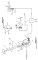
- Figure 1 shows an example of a locking known to perform the two "shif-lock” functions and "key-lock” fitted to motor vehicles at automatic gearbox, preferably on command electronic.
- Figure 2 shows the different positions possible from the ignition key.
- this system includes a electromagnetic actuator 2 controlled by a housing electronics 3 to unlock lever 1 of the position P when the pedal is pressed brake 4 of the vehicle and the ignition key 5 is in position M (or position after contact + APC) or in position A (or accessories + ACC position allowing energize accessories consuming little current, such as a radio, when the engine is stopped).
- the electromagnetic actuator 2 comprises a electromagnet rod 6 acting on a mechanism 7 for allow to dislodge a locking end piece 8 from a corresponding locking hole of an angular sector 9 fixed with respect to the gear lever 1.
- the system includes an electromagnetic actuator 10 controlled by the electronic box 3 to unlock the key contact 5 when lever 1 is in position P.
- the rod solenoid 11 of actuator 10 locks in rotation the barrel when lever 1 is not in position P so that key 5 cannot pass from position "+ ACC" in the "stop” position to authorize the withdrawal of the key 5.
- the actuator 10 when the actuator 10 is supplied by the box 3, the key can be unlocked or removed and if the actuator 10 is not supplied, the key is locked.
- the "shift-lock" function ensures the presence of a driver, by depressing the pedal brake 4, before authorizing the vehicle to drive by the engine and avoid the sudden start of the vehicle to speed engagement.
- the "key-lock" function prevents the extraction of the key from vehicle contact 5 if lever 1 is not in position P. It avoids the risks of blockage the steering wheel by the lock when the vehicle is in movement and complete the shift-lock function by encouraging the driver to leave his vehicle only if lever 1 is in position P.
- the vehicle is also equipped with a function engine start prohibition if lever 1 is not in position P or position N (neutral). She avoids possible jolts on the transmission of the vehicle when the engine starts, as well as inadvertent movement of the vehicle.
- a control logic located for example in the electronic box 3, is designed to control the electromagnetic actuator 2 in the following two cases.
- the first case generally concerns the normal unlocking of lever 1 from position P, that is, the unlocking is carried out using of the electromagnetic actuator 2 when the lever is in position P, that the ignition key 5 is in position + APC or + ACC and that a press is maintained on the foot pedal vehicle brake 4. Pressing the brake pedal 4 is detected by the rear brake light switch 12, of which the information is transmitted to the electronic unit 3.
- the logic of control is arranged so as not to control or supply the electromagnetic actuator 2 instantly if the lever 1 goes to position P after the ignition key 5 is in the + APC or + ACC position and pressing the brake pedal 4 is exerted.
- a timer for example 5 seconds, is started and the electromagnetic actuator 2 is not controlled or powered only after the timer expires if the driver keeps pressing the brake pedal 4.
- the control logic can be adapted to control electromagnetic actuator 2 before the end of this delay by releasing the brake pedal 4 and pressing it again. In all the others case, that is to say with an order of arrival of the information about the lever position in position P, the position of the key in + APC or + ACC and pressing the brake pedal 4, different from the above, supply or control of actuator 2 is instant.
- the second case of unlocking lever 1 of the position P by actuator 2 occurs when the lever 1 is in position P, the ignition key 5 is in position + APC or + ACC and the vehicle moves to a speed V greater than a minimum value, for example about 3 km / h.
- a minimum value for example about 3 km / h.
- the actuator 2 control is interrupted when the ignition key 5 leaves the + ACC position or the lever 1 leaves position P or when pressing the brake pedal 4 is released.
- the first particular case concerns the fact that actuator 2 may not support power permed. In this case, it is tolerated to limit the actuator 2 control at a predetermined duration, by example of a minute respecting the condition following: after this period has elapsed, following a brief release of the brake pedal 4, the actuator 2 is instantly controlled by the electronic unit 3 and must be operational (the effort developed must be enough to unlock the lever).
- the second particular case concerns the gearbox automatic hydraulic without electronic control. For for reasons of simplification, it is tolerated not to manage the following functions mentioned in both actuator 2 control case above: no actuator 2 control when lever 1 returns position P with the brake pedal 4 depressed and inhibition of the locking of lever 1 when the vehicle is moving.
- the control logic allows degraded modes of operation as follows. If the "shift-lock" function uses an electronic computer capable of diagnose a failure of one of the detection of the position of lever 1, of support on the brake pedal 4, higher vehicle speed or equal to 3 km / h or position of the ignition key 5, and if the computer has diagnosed such a failure, the actuator 2 control must be electrically prohibited. In such a case, we must then use the rescue function called "release”. This function allows, thanks to a tool or a key, to manually unlock the lever from position P.
- the control unit is also suitable for order the actuator 10 to unlock the key contact 5 from sensors sensitive to the position of the lever 1 and the ignition key 5 or the movement of one of them, the other being in a given position.
- the first case of actuator 10 control of unlocking the ignition key 5 is where one of these sensors provides a signal that the lever 1 is in position P and the other sensor provides a signal indicating a displacement of the ignition key 5 from its position + APC at its power cut-off position vehicle engine. In this case, the actuator 10 is fed from the falling edge of the signal from key position sensor 5.
- the second actuator 10 control case is that where the lever 1 position sensor provides a signal indicating that this lever is brought to position P before or after the key position sensor 5 provides a contact cut-off signal (therefore independently of the position of the key).
- the third actuator control case 10 for unlock key 5 is where we first cut the engine power contact and lever 1 is brought in position P.
- the actuator 10 is supplied from a rising edge of the sensor signal from the position P of lever 1. It is possible to limit the position sensor status monitoring time P of the lever as will be seen by one of the cases individuals below.
- the control of the actuator 10 is interrupted when the ignition key 5 leaves its position + ACC or that the lever 1 leaves its position P. Interruption of the supply of the actuator 10 can also take place after a delay as explained below in the first particular case of ordering actuator 10.
- actuator 10 like actuator 2 may not withstand permanent feeding. So he is tolerated limiting the actuator supply time 10 at a fixed duration, for example one minute, and respecting the following condition: after sale of this duration, following a brief return of the key contact 5 in position + APC, and provided that the lever either at P, actuator 10 must be ordered instantly and it must be operational (the effort developed must be sufficient to ensure the unlocking).
- a second particular case of actuator control 10 is the one where the calculator associated with the logic of actuator control 10 does not have input + ACC, i.e. it does not receive information coming from the contact terminal + ACC of the lock the ignition key 5.
- it is tolerated to limit the time for monitoring the position status P has a duration which is to be defined on a case by case basis. This limitation is only necessary if the current consumed by the computer when monitoring the state of position P is not permanently acceptable for the vehicle battery. If the lever returns to the position P intervenes after this period, the driver must briefly switch the ignition key 5 to position + APC to supply the electronic unit 3 with a pulse of command before being able to unlock the key 5.
- a third particular case of actuator control 10 concerns the automatic gearbox without electronic unlocking actuator control of the ignition key.
- the actuator 10 is powered with key 5 in position + ACC and lever 1 in position P with possibly a time delay like in the first particular case.
- the actuator control logic 10 allows also degraded modes as follows. If the function "key-lock” uses a computer capable of diagnose a failure of either position sensors of lever 1 and ignition key 5, two cases arise: if there is no function "release", the control logic only takes into account the single sensor in working order to supply actuator 10 (for example if the computer detects a problem with the position detection of the ignition key 5, the actuator 10 will be supplied as soon as lever 1 will be in position P); if there is a function "release”, the power supply to actuator 10 is not mandatory.
- the "release” function allows, thanks to a tool or key, manually unlock the key.
- the vehicle can also be equipped with a function warning of forgetting to return lever 1 to position P.
- a warning means emits a signal audible if the driver's door is opened with the lever 1 in a position other than position P.
- This function completes the shift-lock function by encouraging the driver not to leave the vehicle with the lever in a position other than the P position, for example the neutral position N with the vehicle engine running.
- control logic of the invention described above allows greater security and greater ease of use while respecting the regulations legislative.
Landscapes
- Engineering & Computer Science (AREA)
- General Engineering & Computer Science (AREA)
- Mechanical Engineering (AREA)
- Control Of Transmission Device (AREA)
- Arrangement Or Mounting Of Control Devices For Change-Speed Gearing (AREA)
- Lock And Its Accessories (AREA)
Claims (16)
- Kraftfahrzeug mit automatischem Getriebe, versehen mit einer Steuerlogik für die Funktion Schaltsperre des Schaltknüppels (1) in der Position Parken P oder Funktion "shift-lock" durch einen ersten elektromagnetischen Schalter (2), der während einer vorbestimmten Dauer betätigt wird, zum Beispiel eine Minute, um den Schaltknüppel (1) aus der Position P zu entriegeln, wenn auf das Bremspedal (4) des Fahrzeugs ein Druck ausgeübt wird und der Zündschlüssel (5) sich in der Position "nach der Zündung" (+ APC) oder "Zubehör" (+ ACC) befindet, wobei der erste Schalter (2) beim Loslassen und beim erneuten Heruntertreten des Bremspedals (4) erneut betätigt wird, und nach Ablauf der Dauer der Betätigung des ersten Schalters (2) im Anschluß an ein kurzes Loslassen des Bremspedals (4) der erste Schalter (2) sofort betätigt wird, dadurch gekennzeichnet, daß die Steuerlogik ebenfalls eine Funktion Abziehsperre des Zündschlüssels (5) oder Funktion "key-lock" besitzt, wenn der Schaltknüppel (1) nicht in der Position P ist, durch einen zweiten elektromagnetischen Schalter (10), der zur Entriegelung des Zündschlüssels (5) betätigt wird, und daß die Steuerlogik außerdem so angeordnet ist, daß sie den zweiten Schalter (10) zur Entriegelung des Zündschlüssels (5) von Sensoren aus steuert, die auf die Position des Schaltknüppels (1) und des Zündschlüssels (5) oder auf die Bewegung eines von beiden reagieren, wobei der andere sich in einer bestimmten Position befindet und wenigstens wenn einer der Sensoren anzeigt, daß der Schaltknüppel (1) sich in der Position P befindet oder in die Position P gebracht wird.
- Kraftfahrzeug gemäß Anspruch 1, dadurch gekennzeichnet, daß der zweite Schalter (10) zur Entriegelung des Zündschlüssels (5) betätigt wird, wenn einer der besagten Sensoren ein Signal ausgibt, das anzeigt, daß der Schaltknüppel in die Position P gebracht wurde, bevor oder nachdem der andere Sensor ein Signal zum Abbruch des Kontaktes ausgibt.
- Kraftfahrzeug gemäß Anspruch 1 oder 2, dadurch gekennzeichnet, daß der zweite Schalter (10) zur Entriegelung des Zündschlüssels (5) während einer vorbestimmten Dauer, zum Beispiel einer Minute, betätigt wird, und nach Ablauf dieser Dauer im Anschluß an eine kurze Rückkehr des Schlüssels in die Position "nach der Zündung" (+ APC), der zweite Schalter (10) unverzüglich betätigt wird.
- Kraftfahrzeug gemäß Anspruch 1, dadurch gekennzeichnet, daß der zweite Schalter (10) zur Entriegelung des Zündschlüssels (5) betätigt wird, wenn einer der besagten Sensoren ein Signal ausgibt, das eine Verstellung des Zündschlüssels (5) von seiner Position "nach der Zündung" (+ APC) in seine Position Abbruch des Kontakts anzeigt und der andere Sensor ein Signal ausgibt, das anzeigt, daß der Schaltknüppel (1) in die Position P gebracht wurde.
- Kraftfahrzeug gemäß Anspruch 4, dadurch gekennzeichnet, daß der zweite Schalter (10) zur Entriegelung des Zündschlüssels (5) von der aufsteigenden Front des Signals des anderen besagten Sensors aus gesteuert wird.
- Kraftfahrzeug gemäß Anspruch 4 oder 5, dadurch gekennzeichnet, daß, in dem Falle, in dem der Rechner der Steuerlogik keinen Eingang "Zubehör" (+ ACC) des Kontaktschlüssels (5) besitzt, dieser Rechner den Sensor für den Zustand der Position des Schaltknüppels (1) während einer vorbestimmten begrenzten Dauer überwacht und wenn die Rückkehr des Schaltknüppels (1) in die Position P nach Beendigung dieser vorbestimmten Dauer erfolgt, erlaubt eine kurze Rückkehr des Schlüssels in die Position "nach der Zündung" (+ APC) die Betätigung des zweiten Schalters (10) zur Entriegelung des Zündschlüssels (5).
- Kraftfahrzeug gemäß einem der vorherigen Ansprüche, dadurch gekennzeichnet, daß die Steuerlogik ebenfalls so angeordnet ist, daß der erste Schalter (2) zur Entriegelung des Schaltknüppels (1) nicht unverzüglich betätigt wird, wenn letzterer in die Position P übergeht, während der Zündschlüssel (5) sich in der Position "nach der Zündung" (+ APC) oder "Zubehör" (+ ACC) befindet und wenn ein Druck auf das Bremspedal (4) ausgeübt wird.
- Kraftfahrzeug gemäß Anspruch 7, dadurch gekennzeichnet, daß der erste elektromagnetische Schalter (2) zur Entriegelung des Schaltknüppels (1) in der Position P betätigt wird, wenn der Schaltknüppel (1) sich in der Position P befindet, der Zündschlüssel (5) in der Position "nach der Zündung" (+ APC) oder "Zubehör" (+ ACC) ist und das Kraftfahrzeug sich in einer höheren Geschwindigkeit als ein Mindestwert, zum Beispiel ungefähr 3 km/h, fortbewegt.
- Kraftfahrzeug gemäß Anspruch 1, dadurch gekennzeichnet, daß der zweite Schalter (10) zur Entriegelung des Zündschlüssels (5) betätigt wird, wenn einer der besagten Sensoren ein Signal ausgibt, das anzeigt, daß der Schaltknüppel (1) in der Position P ist, und der andere Sensor ein Signal ausgibt, das eine Verstellung des Zündschlüssels (5) aus seiner Position "nach der Zündung" (+ APC) in seine Position Abbruch des Kontaktes anzeigt.
- Kraftfahrzeug gemäß Anspruch 9, dadurch gekennzeichnet, daß der zweite Schalter (10) zur Entriegelung des Zündschlüssels (5) von der absteigenden Front des Signals des anderen besagten Sensors aus gesteuert wird.
- Kraftfahrzeug gemäß einem der vorherigen Ansprüche, dadurch gekennzeichnet, daß der erste Schalter (2) zur Entriegelung des Schaltknüppels (1) der Position P erst nach Ablauf einer vorbestimmten Verzögerungszeit, zum Beispiel 5 Sekunden, betätigt wird, wenn das Bremspedal (4) weiterhin heruntergetreten wird.
- Kraftfahrzeug gemäß Anspruch 11, dadurch gekennzeichnet, daß die Steuerlogik ebenfalls so angepaßt ist, daß sie den ersten besagten Schalter (2) vor Ablauf der Verzögerungszeit bei Loslassen des Bremspedals (4) und bei erneutem Heruntertreten desselben betätigt.
- Kraftfahrzeug gemäß einem der vorherigen Ansprüche, dadurch gekennzeichnet, daß ein elektronischer Rechner für die Funktion "shift-lock" zur Feststellung eines Versagens einer der Sensoren der Position des Schaltknüppels in der Position P, der Erfassung des auf das Bremspedal (4) ausgeübten Drucks, der Geschwindigkeit des Kraftfahrzeugs oder der Position des Zündschlüssels (5) verwendet wird und zur Verhinderung der Betätigung des ersten Schalters (2) zur Entriegelung des Schaltknüppels (1) bei durch den Rechner festgestelltem Versagen eines Sensors, so daß der Fahrer auf eine "release" genannte Hilfsfunktion zurückgreifen kann, die es mittels eines Werkzeugs oder Schlüssels erlaubt, den Schaltknüppel (1) per Hand aus der Position P zu entriegeln.
- Kraftfahrzeug gemäß einem der vorherigen Ansprüche, dadurch gekennzeichnet, daß ein elektronischer Rechner für die Funktion "key-lock" zur Feststellung eines Versagens eines der Sensoren zur Feststellung der Position des Schaltknüppels (1) in der Position P oder der Position des Zündschlüssels (5) verwendet wird und wenn der Rechner ein Versagen eines der Sensoren feststellt, wird der zweite Schalter (10) zur Entriegelung des Zündschlüssels (5) bei Fehlen der "release" genannten Hilfsfunktion, die es mittels eines Werkzeugs oder Schlüssels erlaubt, den Zündschlüssel per Hand zu entriegeln, unter alleiniger Berücksichtigung des einzigen funktionstüchtigen Sensors betätigt.
- Kraftfahrzeug gemäß einem der vorherigen Ansprüche, dadurch gekennzeichnet, daß es ein Signalgebungsmittel umfaßt, das ein Tonsignal ausgibt, wenn die Fahrertür offen ist während der Schaltknüppel (1) nicht in der Position P ist.
- Kraftfahrzeug gemäß einem der vorherigen Ansprüche, dadurch gekennzeichnet, daß das Getriebe mit einer elektronischen Steuerung ausgestattet ist.
Applications Claiming Priority (2)
| Application Number | Priority Date | Filing Date | Title |
|---|---|---|---|
| FR9600622A FR2743762B1 (fr) | 1996-01-19 | 1996-01-19 | Vehicule automobile a boite de vitesses equipe d'une logique de commande a fonction de verrouillage du levier de vitesses en position parking et fonction de verrouillage de la clef de contact |
| FR9600622 | 1996-01-19 |
Publications (2)
| Publication Number | Publication Date |
|---|---|
| EP0785380A1 EP0785380A1 (de) | 1997-07-23 |
| EP0785380B1 true EP0785380B1 (de) | 2000-05-10 |
Family
ID=9488282
Family Applications (1)
| Application Number | Title | Priority Date | Filing Date |
|---|---|---|---|
| EP19960402735 Expired - Lifetime EP0785380B1 (de) | 1996-01-19 | 1996-12-13 | Kraftfahrzeug mit automatischem Getriebe versehen mit einer Steuerlogik für die Funktionen Schaltsperre und Zündschlüsselabziehsperre |
Country Status (6)
| Country | Link |
|---|---|
| US (1) | US6059687A (de) |
| EP (1) | EP0785380B1 (de) |
| JP (1) | JP4070258B2 (de) |
| DE (1) | DE69608235T2 (de) |
| ES (1) | ES2148707T3 (de) |
| FR (1) | FR2743762B1 (de) |
Families Citing this family (38)
| Publication number | Priority date | Publication date | Assignee | Title |
|---|---|---|---|---|
| US5862899A (en) * | 1997-03-10 | 1999-01-26 | Ut Automotive Dearborn, Inc. | Brake-shift interlock |
| DE19752752B4 (de) * | 1997-11-28 | 2007-01-25 | Bayerische Motoren Werke Ag | Getriebesteuereinrichtung mit einer elektronischen Steuereinrichtung für ein Kraftfahrzeug mit einem Automatikgetriebe |
| GB2332250B (en) * | 1997-12-09 | 2002-06-19 | Rover Group | Shift lever with lock mechanism |
| DE19818867C1 (de) * | 1998-04-28 | 1999-11-25 | Daimler Chrysler Ag | Wähleinrichtung für ein automatisches Kraftfahrzeuggetriebe |
| DE19857837A1 (de) * | 1998-12-15 | 2000-06-21 | Mannesmann Vdo Ag | Bedienvorrichtung |
| DE19913005A1 (de) * | 1999-03-23 | 2000-10-05 | Audi Ag | Schaltvorrichtung für Kraftfahrzeuggetriebe |
| DE10005328A1 (de) * | 2000-02-08 | 2001-08-09 | Zf Lemfoerder Metallwaren Ag | Schaltvorrichtung für ein Automatikgetriebe |
| SE522613C2 (sv) * | 2000-07-26 | 2004-02-24 | Kongsberg Automotive Ab | Manöveranordning i form av ett växelreglage |
| DE10147031B4 (de) * | 2000-09-27 | 2012-11-29 | Marquardt Gmbh | Zündschloß für ein Kraftfahrzeug |
| DE10101983A1 (de) * | 2001-01-18 | 2002-07-25 | Bayerische Motoren Werke Ag | Sicherheitseinrichtung für ein Kraftfahrzeug |
| WO2002066279A1 (fr) * | 2001-02-20 | 2002-08-29 | Nissan Motor Co.,Ltd. | Dispositif de commutation d'etat pour vehicule |
| DE10130335C1 (de) * | 2001-06-26 | 2003-02-13 | Zf Lemfoerder Metallwaren Ag | Ver- und Entriegelungsmechanismus mit Elektromagnet |
| US6592492B1 (en) * | 2001-08-31 | 2003-07-15 | Pontiac Coil, Inc. | Brake transmission shift interlock and park lock system |
| US6989611B2 (en) * | 2001-10-09 | 2006-01-24 | Kabushiki Kaisha Tokai Rika Denki Seisakusho | Electronic automobile anti-theft apparatus |
| DE10157459C1 (de) * | 2001-11-23 | 2003-05-28 | Daimler Chrysler Ag | Betätigungseinrichtung für ein Automatikgetriebe eines Kraftfahrzeugs |
| US6689014B2 (en) * | 2002-01-30 | 2004-02-10 | International Truck Intellectual Property Company, Llc | Park position locking system for automatic transmission shifter |
| DE10209551B4 (de) * | 2002-03-04 | 2011-06-01 | Volkswagen Ag | Verfahren und Vorrichtung zur Steuerung einer Abzugssperre eines Zündschlüssels eines Kraftfahrzeugs |
| FR2837253B1 (fr) * | 2002-03-15 | 2004-08-06 | Renault | Procede pour verrouiller/deverrouiller la position de stationnement d'une boite de vitesses automatique d'un vehicule automobile |
| EP1506359A2 (de) * | 2002-05-10 | 2005-02-16 | LuK Lamellen und Kupplungsbau Beteiligungs KG | Verfahren und vorrichtung zum betrieb insbesondere eines automatischen bzw. automatisierten getriebes mit parksperre bzw. wegrollsicherung |
| US6817966B2 (en) | 2002-08-29 | 2004-11-16 | Visteon Global Technologies, Inc. | Brake shift Interlock system with a single park position switch |
| DE10255214B4 (de) * | 2002-11-27 | 2006-05-04 | Daimlerchrysler Ag | Sperreinrichtung für einen Wahlhebel und Verfahren zum Sperren eines Wahlhebels |
| US6913104B2 (en) * | 2003-02-26 | 2005-07-05 | Mtd Products Inc | Shift interlock mechanism |
| US20040226801A1 (en) * | 2003-05-15 | 2004-11-18 | De Jonge Robert A. | Vehicle shifter |
| US7568404B2 (en) * | 2004-07-26 | 2009-08-04 | Ghsp, A Division Of Jsj Corporation | Shifter having neutral lock |
| KR100916343B1 (ko) * | 2007-07-30 | 2009-09-11 | 동아대학교 산학협력단 | 시동버튼을 이용한 자동차 엔진 시동장치 및 방법 |
| DE102009037580B4 (de) * | 2009-08-14 | 2023-05-17 | Volkswagen Ag | Verfahren zum Halten eines Schlüssels in einem Schloss für ein Fahrzeug, Verfahren zur Herstellung eines Fahrzeugs mit Zündschlüsselabzugssperre, Zündschlüsselabzugssperre und Fahrzeug |
| JP5500524B2 (ja) * | 2010-05-25 | 2014-05-21 | 株式会社ユーシン | 車輌用ロック装置 |
| JP5633728B2 (ja) * | 2010-06-04 | 2014-12-03 | 株式会社ユーシン | 電動アクチュエータの制御装置 |
| US9032830B2 (en) * | 2010-10-29 | 2015-05-19 | Ford Global Technologies, Llc | Transmission shift selector assembly |
| EP2682300A1 (de) * | 2011-03-03 | 2014-01-08 | Toyota Jidosha Kabushiki Kaisha | Umschaltsperre für ein fahrzeug |
| US20130080029A1 (en) * | 2011-09-23 | 2013-03-28 | GM Global Technology Operations LLC | Fail safe electronic throttle control pedal sensor |
| JP5872271B2 (ja) * | 2011-12-07 | 2016-03-01 | 株式会社東海理化電機製作所 | シフト装置 |
| US9371057B2 (en) | 2012-01-06 | 2016-06-21 | Kamol Kantajaraniti | Vehicle security locking system having a driving function locking device |
| US9475460B2 (en) | 2012-02-24 | 2016-10-25 | Kamol Kantajaraniti | Gear lever locking device |
| US10677344B2 (en) | 2017-03-10 | 2020-06-09 | Kuster North America, Inc. | Auto return to park rotary shifter |
| US10788123B2 (en) | 2017-03-10 | 2020-09-29 | Kuster North America, Inc. | Rotary shifter with a DC motor driving lock mechanism |
| US10591058B2 (en) | 2017-03-10 | 2020-03-17 | Kuster North America, Inc. | Auto return to park rotary and lever style shifter |
| JP7137591B2 (ja) * | 2020-03-30 | 2022-09-14 | 本田技研工業株式会社 | シフト装置、および、シフト装置の制御方法 |
Family Cites Families (19)
| Publication number | Priority date | Publication date | Assignee | Title |
|---|---|---|---|---|
| JPS57134331A (en) * | 1981-02-09 | 1982-08-19 | Nissan Motor Co Ltd | Controller for automatic speed change gear |
| JPH01182135A (ja) * | 1988-01-12 | 1989-07-20 | Yoshio Mizuguchi | At車のシフトレバーのn又はp位置検出装置 |
| US4887702A (en) * | 1988-06-13 | 1989-12-19 | United Technologies Automotive, Inc. | Brake/shift interlock for an automatic transmission shift control mechanism |
| JPH0719879Y2 (ja) * | 1988-12-27 | 1995-05-10 | 富士重工業株式会社 | At車用シフトロック装置 |
| EP0378244A3 (de) * | 1989-01-13 | 1990-09-12 | Nissan Motor Co., Ltd. | Steuerungsanlage für automatische Fahrzeuggetriebe |
| US5251723A (en) * | 1989-02-23 | 1993-10-12 | Sparton Corporation | Service brake and shift lever interlock system |
| US5181592A (en) * | 1990-06-11 | 1993-01-26 | Sparton Corporation | Shift lever interlock system |
| US5211271A (en) * | 1991-01-17 | 1993-05-18 | Grand Haven Stamped Products Company, Div. Of Jsj Corp. | Lockout mechanism and system for vehicle shifter |
| US5096033A (en) * | 1991-01-17 | 1992-03-17 | Grand Haven Stamped Products Company | Lockout mechanism and system for vehicle shifter |
| JP2842951B2 (ja) * | 1991-03-29 | 1999-01-06 | 日産自動車株式会社 | 自動変速機のキーインターロック装置 |
| US5431266A (en) * | 1992-12-02 | 1995-07-11 | Nissan Motor Co., Ltd. | Shift lock system |
| JP3329534B2 (ja) * | 1993-10-20 | 2002-09-30 | 株式会社東海理化電機製作所 | シフトレバー装置 |
| JPH07266908A (ja) * | 1994-03-31 | 1995-10-17 | Fuji Kiko Co Ltd | シフトレバー装置 |
| US5445575A (en) * | 1994-05-02 | 1995-08-29 | Sundeen; Arthur R. | Ignition lock cylinder and gear shift lever interlock |
| DE4426533C1 (de) * | 1994-07-27 | 1996-03-07 | Porsche Ag | Vorrichtung zur Verriegelung des Zündschlüssels eines Kraftfahrzeuges mit dem Wählhebel eines Automatikgetriebes |
| US5562568A (en) * | 1994-08-18 | 1996-10-08 | Dura Mechanical Components, Inc. | Brake-transmission-ignition key interlock system |
| US5489246A (en) * | 1994-08-29 | 1996-02-06 | Pontiac Coil, Inc. | Electronic park lock |
| US5647818A (en) * | 1995-03-27 | 1997-07-15 | Pontiac Coil, Inc. | Shifter interlock for an automatic transmission |
| US5752414A (en) * | 1996-05-24 | 1998-05-19 | Teleflex Incorporated | Cable operated brake/ignition/transmission interlock |
-
1996
- 1996-01-19 FR FR9600622A patent/FR2743762B1/fr not_active Expired - Lifetime
- 1996-12-13 DE DE69608235T patent/DE69608235T2/de not_active Expired - Lifetime
- 1996-12-13 ES ES96402735T patent/ES2148707T3/es not_active Expired - Lifetime
- 1996-12-13 EP EP19960402735 patent/EP0785380B1/de not_active Expired - Lifetime
-
1997
- 1997-01-17 JP JP00671797A patent/JP4070258B2/ja not_active Expired - Fee Related
- 1997-01-17 US US08/785,055 patent/US6059687A/en not_active Expired - Lifetime
Also Published As
| Publication number | Publication date |
|---|---|
| JP4070258B2 (ja) | 2008-04-02 |
| EP0785380A1 (de) | 1997-07-23 |
| FR2743762B1 (fr) | 1998-03-20 |
| JPH09309354A (ja) | 1997-12-02 |
| DE69608235D1 (de) | 2000-06-15 |
| FR2743762A1 (fr) | 1997-07-25 |
| ES2148707T3 (es) | 2000-10-16 |
| DE69608235T2 (de) | 2000-11-30 |
| US6059687A (en) | 2000-05-09 |
Similar Documents
| Publication | Publication Date | Title |
|---|---|---|
| EP0785380B1 (de) | Kraftfahrzeug mit automatischem Getriebe versehen mit einer Steuerlogik für die Funktionen Schaltsperre und Zündschlüsselabziehsperre | |
| FR2790228A1 (fr) | Dispositif de commande d'un systeme de regulation d'allure pour vehicule automobile | |
| FR2765840A1 (fr) | Vehicule automobile | |
| FR2697783A1 (fr) | Dispositif de commande automatique d'un embrayage à friction d'un véhicule automobile en fonctionnement d'urgence. | |
| FR2770466A1 (fr) | Vehicule automobile equipe d'un dispositif de manoeuvre automatisee d'un embrayage | |
| FR2785237A1 (fr) | Procede de commande d'un accouplement | |
| FR2814132A1 (fr) | Dispositif de securite pour vehicule automobile | |
| EP1027239B1 (de) | Bremsanlage und kraftfahrzeug mit vorrichtung zur automatischen abstandsregelung | |
| WO2014049264A1 (fr) | Procédé et dispositif de gestion d'arret et de redemarrage d'un moteur de vehicule automobile et véhicule automobile comprenant un tel dispositif | |
| FR2784433A1 (fr) | Procede et dispositif pour influencer, pendant la conduite d'un vehicule automobile, une manoeuvre a laquelle est lie un changement de rapport de transmission | |
| FR2695084A1 (fr) | Dispositif de commande d'un embrayage à friction de véhicule automobile. | |
| FR2906515A1 (fr) | Procede et dispositif de gestion du freinage d'un vehicule automobile. | |
| FR2793290A1 (fr) | Dispositif pour actionner un embrayage a friction | |
| FR2798174A1 (fr) | Procede et systeme de commande d'un embrayage de vehicule automobile | |
| FR2780690A1 (fr) | Vehicule automobile | |
| EP0749876B1 (de) | Kraftfahrzeug-Bremsanlage | |
| JP2001349268A (ja) | 車両用スタータ駆動装置 | |
| FR2806669A1 (fr) | Procede de commande d'un systeme d'entrainement et systeme pour sa mise en oeuvre | |
| FR2788734A1 (fr) | Systeme d'entrainement et procede de commande d'un tel systeme | |
| FR2813837A1 (fr) | Procede et dispositif de commande de freinage | |
| FR2755486A1 (fr) | Procede et systeme d'entrainement pour commander le demarrage du moteur d'un vehicule | |
| EP1053919B1 (de) | Verfahren und Vorrichtung zum unterstützten Anlassen des Motors eines Kraftfahrzeuges | |
| FR2655121A1 (fr) | Dispositif de commande de boite de vitesses automatique, notamment pour vehicule automobile. | |
| EP1188631B1 (de) | Verfahren und Vorrichtung zur Bremssteuerung | |
| JP4863012B2 (ja) | 車両用制御装置 |
Legal Events
| Date | Code | Title | Description |
|---|---|---|---|
| PUAI | Public reference made under article 153(3) epc to a published international application that has entered the european phase |
Free format text: ORIGINAL CODE: 0009012 |
|
| AK | Designated contracting states |
Kind code of ref document: A1 Designated state(s): DE ES GB IT SE |
|
| 17P | Request for examination filed |
Effective date: 19971114 |
|
| 17Q | First examination report despatched |
Effective date: 19990226 |
|
| GRAG | Despatch of communication of intention to grant |
Free format text: ORIGINAL CODE: EPIDOS AGRA |
|
| GRAG | Despatch of communication of intention to grant |
Free format text: ORIGINAL CODE: EPIDOS AGRA |
|
| GRAH | Despatch of communication of intention to grant a patent |
Free format text: ORIGINAL CODE: EPIDOS IGRA |
|
| GRAH | Despatch of communication of intention to grant a patent |
Free format text: ORIGINAL CODE: EPIDOS IGRA |
|
| GRAA | (expected) grant |
Free format text: ORIGINAL CODE: 0009210 |
|
| AK | Designated contracting states |
Kind code of ref document: B1 Designated state(s): DE ES GB IT SE |
|
| REF | Corresponds to: |
Ref document number: 69608235 Country of ref document: DE Date of ref document: 20000615 |
|
| ITF | It: translation for a ep patent filed | ||
| GBT | Gb: translation of ep patent filed (gb section 77(6)(a)/1977) |
Effective date: 20000707 |
|
| REG | Reference to a national code |
Ref country code: ES Ref legal event code: FG2A Ref document number: 2148707 Country of ref document: ES Kind code of ref document: T3 |
|
| PLBE | No opposition filed within time limit |
Free format text: ORIGINAL CODE: 0009261 |
|
| STAA | Information on the status of an ep patent application or granted ep patent |
Free format text: STATUS: NO OPPOSITION FILED WITHIN TIME LIMIT |
|
| 26N | No opposition filed | ||
| REG | Reference to a national code |
Ref country code: GB Ref legal event code: IF02 |
|
| PGFP | Annual fee paid to national office [announced via postgrant information from national office to epo] |
Ref country code: SE Payment date: 20061127 Year of fee payment: 11 |
|
| REG | Reference to a national code |
Ref country code: GB Ref legal event code: 746 Effective date: 20070119 |
|
| PGFP | Annual fee paid to national office [announced via postgrant information from national office to epo] |
Ref country code: ES Payment date: 20071207 Year of fee payment: 12 |
|
| PGFP | Annual fee paid to national office [announced via postgrant information from national office to epo] |
Ref country code: IT Payment date: 20071211 Year of fee payment: 12 |
|
| EUG | Se: european patent has lapsed | ||
| PG25 | Lapsed in a contracting state [announced via postgrant information from national office to epo] |
Ref country code: SE Free format text: LAPSE BECAUSE OF NON-PAYMENT OF DUE FEES Effective date: 20071214 |
|
| REG | Reference to a national code |
Ref country code: ES Ref legal event code: FD2A Effective date: 20081215 |
|
| PG25 | Lapsed in a contracting state [announced via postgrant information from national office to epo] |
Ref country code: ES Free format text: LAPSE BECAUSE OF NON-PAYMENT OF DUE FEES Effective date: 20081215 |
|
| PGFP | Annual fee paid to national office [announced via postgrant information from national office to epo] |
Ref country code: GB Payment date: 20101201 Year of fee payment: 15 |
|
| GBPC | Gb: european patent ceased through non-payment of renewal fee |
Effective date: 20121213 |
|
| PG25 | Lapsed in a contracting state [announced via postgrant information from national office to epo] |
Ref country code: IT Free format text: LAPSE BECAUSE OF NON-PAYMENT OF DUE FEES Effective date: 20081213 Ref country code: GB Free format text: LAPSE BECAUSE OF NON-PAYMENT OF DUE FEES Effective date: 20121213 |
|
| PGFP | Annual fee paid to national office [announced via postgrant information from national office to epo] |
Ref country code: DE Payment date: 20151119 Year of fee payment: 20 |
|
| REG | Reference to a national code |
Ref country code: DE Ref legal event code: R071 Ref document number: 69608235 Country of ref document: DE |