EP0773691B1 - Projecteur à cristaux liquides - Google Patents
Projecteur à cristaux liquides Download PDFInfo
- Publication number
- EP0773691B1 EP0773691B1 EP96117779A EP96117779A EP0773691B1 EP 0773691 B1 EP0773691 B1 EP 0773691B1 EP 96117779 A EP96117779 A EP 96117779A EP 96117779 A EP96117779 A EP 96117779A EP 0773691 B1 EP0773691 B1 EP 0773691B1
- Authority
- EP
- European Patent Office
- Prior art keywords
- projection lens
- light
- liquid crystal
- aperture diaphragm
- image
- Prior art date
- Legal status (The legal status is an assumption and is not a legal conclusion. Google has not performed a legal analysis and makes no representation as to the accuracy of the status listed.)
- Expired - Lifetime
Links
Images


Classifications
-
- H—ELECTRICITY
- H04—ELECTRIC COMMUNICATION TECHNIQUE
- H04N—PICTORIAL COMMUNICATION, e.g. TELEVISION
- H04N9/00—Details of colour television systems
- H04N9/12—Picture reproducers
- H04N9/31—Projection devices for colour picture display, e.g. using electronic spatial light modulators [ESLM]
- H04N9/3102—Projection devices for colour picture display, e.g. using electronic spatial light modulators [ESLM] using two-dimensional electronic spatial light modulators
- H04N9/3105—Projection devices for colour picture display, e.g. using electronic spatial light modulators [ESLM] using two-dimensional electronic spatial light modulators for displaying all colours simultaneously, e.g. by using two or more electronic spatial light modulators
-
- H—ELECTRICITY
- H04—ELECTRIC COMMUNICATION TECHNIQUE
- H04N—PICTORIAL COMMUNICATION, e.g. TELEVISION
- H04N9/00—Details of colour television systems
- H04N9/12—Picture reproducers
- H04N9/31—Projection devices for colour picture display, e.g. using electronic spatial light modulators [ESLM]
- H04N9/3141—Constructional details thereof
- H04N9/315—Modulator illumination systems
- H04N9/3164—Modulator illumination systems using multiple light sources
Definitions
- the present invention relates to a liquid crystal projector in which an illumination light from a light source is irradiated onto a liquid crystal panel, especially, a reflective and scattering type liquid crystal panel, and an image light which was obtained by modulating the illumination light by the liquid crystal panel is enlargedly projected onto a screen by a projection lens.
- a system disclosed in Fig. 1 of Japanese Patent Application Laid-Open No. 4-194921 has been conventionally known as a liquid crystal projector using the reflective and scattering type liquid crystal panel.
- the system comprises an aperture diaphragm (corresponding to the shielding mask 7), a mirror (corresponding to the reflecting mirror 8), a convex lens (corresponding to the condenser lens 6), and reflective and scattering type liquid crystal panels (corresponding to the reflective and scattering type liquid crystal device 5R for red, the reflective and scattering type liquid crystal device 5G for green, and the reflective and scattering type liquid crystal device 5B for blue).
- an illumination light from a light source is irradiated onto the liquid crystal panels via the mirror and the convex lens, and is modulated to an image light and is reflected by the liquid crystal panels.
- the reflected image light is enlargedly projected via the convex lens and the aperture diaphragm onto a screen by a projection lens.
- Fig. 9 is a schematic diagram for explaining the basic operation of a liquid crystal projector using a reflecting and scattering type liquid crystal panel.
- An illumination light 46 emitted from a light source 41 passes through an aperture diaphragm 42 on a light-incoming side and enters a reflecting and scattering type liquid crystal panel 43.
- the light is reflected by the liquid crystal panel 43, transmitted through an aperture diaphragm 44 for a projection lens, and enlargedly projected onto a screen (not shown) by a projection lens 45.
- picture elements of the liquid crystal panel 43 diffuse the entering light according to a voltage to be applied.
- a normally-reflected light 47 indicated by a solid line shows a reflection light which is not diffused.
- a diffused reflection light 48 indicated by a broken line shows a reflection light which is diffused by the liquid crystal panel.
- Most of the normally-reflected lights 47 pass through the aperture diaphragm 44 and arrive at the screen via the projection lens 45.
- Most of the diffused reflection lights 48 are shielded by the aperture diaphragm 44, a point on the screen, which corresponds to a picture element which diffused the light is dark.
- the illumination light from the light source is converted to the image light.
- the liquid crystal projector with such a structure can obtain brighter and larger image on a screen than an image of a liquid crystal projector using a TN (twisted nematic) type liquid crystal panel. Since the reflecting type liquid crystal panel is used, the numerical aperture of each picture element can be set larger than that of a transmitting type liquid crystal panel, so that a brighter image can be obtained.
- optical paths in the optical system are bent in the reflecting type liquid crystal panel, the optical system is smaller than that of a projector using the transmitting type liquid crystal panel.
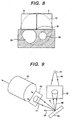
- Fig. 10 is a schematic diagram of a side face of an optical system of a conventional reflective and scattering type liquid crystal projector.
- An illumination light 61 emitted from a metal halide lamp 51 as a light source is converted to an almost parallel light by a condenser reflector 52 and is condensed via a condenser lens 53 onto a mirror 54 (corresponding to the aperture diaphragm 42 on the light incoming side in Fig. 9).
- the light After being reflected, the light enters a dichroic prism 56 via a plane-convex lens 55.
- the illumination light 61 is separated by the dichroic prism 56 into a red light 62r, a blue light 62b, and a green light 62g.
- the lights 62r, 62b, and 62g are modulated to image lights by reflecting and scattering type liquid crystal panels 57r, 57b, and 57g, respectively. Then, a red image light 63r, a blue image light 63b, and a green image light 63g are reflected.
- the image lights 63r, 63b, and 63g are photocolorsynthesized by the dichroic prism 56, thereby deriving an outgoing image light 64.
- the outgoing image light 64 enters a projection lens 59 through the plane-convex lens 55 and an aperture diaphragm 58 and is projected onto a screen (not shown).
- the mirror 54 and the aperture diaphragm 58 are positioned within a focal plane of the projection lens 59 and are arranged so as to be adjacent in the vertical direction with respect to the optical axis 19 of the projection lens 59 as a center.
- the projection lens 59 effectively takes in the image lights 63r, 63b, and 63g which are normally reflected by the liquid crystal panels 57r, 57b, and 57g.
- Fig. 11 is a front view of a focal plane 60 of the projection lens 59 of the conventional liquid crystal projector shown in Fig. 10.
- the mirror 54 is arranged on the upper side of the optical axis 19 of the focal plane 60 and the aperture diaphragm 58 is arranged on the lower side of the optical axis 19. Since the condenser reflector 52 as a light source has an ellipsoid of revolution or paraboloid of revolution, the aperture diaphragm 58 has an almost circle shape and the mirror 54 has a square shape.
- the actually-valid area of the aperture diaphragm 58 is about 25% for the focal plane 60 of the projection lens 59.
- the area of the aperture diaphragm 58 is set so that the F-number for the projection lens is equal to 4 (hereinlater, written as F4)
- the F-number of the focal plane 60 of the projection lens 59 has to correspond to F2.
- the second problem relates to contrast of an image.
- the mirror on the light-incoming side has the area corresponding to that the F-number of the projection lens is equal to F11 to F4 in order to secure the light amount which enters the liquid crystal panel.
- the area of the aperture diaphragm In order to obtain the maximum value of the brightness on the screen, it is necessary to set the area of the aperture diaphragm to a size so that the F-number is equal to F5.6 to F4.
- the contrast of the image ranges from (20 : 1) to (40 : 1) in this instance.
- the absolute value of the contrast is inferior to a value which ranges from (80 : 1) to (200 : 1) when the F-number is increased from F8 to F11.
- Table 1 shows an example of effective contrast when the image of the liquid crystal projector is observed in a light room and a dark room. Performance of the main body Effective value of contrast Brightness Contrast Room with lightness of 200lx Room with lightness of 25lx All white display All black display Contrast 4000lx 100lx 40:1 14:1 32:1 2000lx 25lx 80:1 10:1 41:1
- a method of increasing an output of a lamp of a light source is considered to improve the brightness without enlarging the areas of the mirror and the aperture diaphragm.
- the output of the lamp is increased, the light emitting unit of the lamp becomes large, so that it is difficult to effectively condense the illumination light onto the mirror.
- Much improvement in brightness cannot be expected and a new problem that the life of the lamp is shortened is caused.
- liquid crystal projector using the conventional liquid crystal panel has another problem regarding the position of an exhaust port from which residual heat in the set is discharged.
- the problem is naturally caused also in the case where the above-mentioned reflective and scattering type liquid crystal panel is used.
- the problem occurs not only when the reflective and scattering type liquid crystal panel is used, but also when liquid crystal panels in other types (for example, a transmitting type liquid crystal panel) are used.
- a system shown in Fig. 1 of Japanese Patent Application Laid-Open No. 4-68689 is known as a conventional liquid crystal projector.
- the system comprises a light source (corresponding to the light source 1), dichroic mirrors (corresponding to the dichroic mirrors 10 and 14), transmitting type liquid crystal panels (corresponding to the liquid crystal panels 12a to 12c), and a projection lens.
- An illumination light emitted from the light source is separated to illumination lights of the three primary colors of red, blue, and green by the dichroic mirrors.
- the illumination lights are transmitted through the liquid crystal panels, respectively, and modulated into image lights.
- the image lights of red, blue, and green are again photocolorsynthesized by the dichroic mirrors and are enlargedly projected onto a screen by the projection lens.
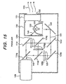
- Fig. 15 is a side view of the optical system of a conventional liquid crystal projector.
- An illumination light 141 emitted from a metal halide lamp 121 as a light source is reflected by a condenser reflector 122 for transmitting infrared and ultraviolet rays and is separated into lights of the three primary colors of red, blue, and green by dichroic mirrors 124r, 124b, and 124g via a reflecting mirror 123.
- the illumination lights After being transmitted through a plane-convex lens 125, the illumination lights are modulated to image lights 142 by transmitting type liquid crystal panels 126r, 126b, and 126g and pass through the panels.
- the image lights 142 of the three primary colors of red, blue, and green are photocolorsynthesized by dichroic mirrors 114r, 114b, and 114g and are enlargedly projected by a projection lens 129.
- Infrared and ultraviolet rays 143 emitted from the metal halide lamp 121 as a light source are transmitted through the infrared and ultraviolet rays transmitting condenser reflector 122 and are absorbed by the inside of a lamp house 130, thereby becoming heat.
- the heat stuffed inside the lamp house 130 is backwardly discharged from an exhaust port 132 which is positioned on the rear face of the set by an exhaust fan 131.
- the light emitting face of the projection lens when the light emitting face of the projection lens is set to the front of the set, the light source and the projection lens are positioned on a diagonal line of the set and the light source is located backward in the set. Consequently, the exhaust port from which residual heat from the light source is discharged is arranged on either rear face or right or left side face of the set.
- the liquid crystal projector tends to use a metal halide lamp or halogen lamp as a light source which generates high power like 150W to 400W in order to realize brightness of an image.
- a temperature near the lamp house is very high due to the infrared and ultraviolet rays generated by the lamp.
- the temperature of the exhaust exceeds 40°C.
- the hot air from the exhaust port is conventionally a problem which cannot be ignored.
- the hot air is discharged toward the operator or the observer of the image when the liquid crystal projector is used.
- the peripheral equipment such as personal computer, VTR, LD, and the like as an apparatus of generating the image signal is often arranged beside or on the back side of the set.
- the exhaust port of the liquid crystal projector is positioned adjacent to a sucking port of a cooling device of the peripheral equipment. The hot air from the exhaust port is sucked by the sucking port of the peripheral equipment, so that a problem of a failure of the peripheral equipment due to the heat occurs.
- the liquid crystal panel arranged near the light source in the set is influenced by the heat of the light source, causing deterioration of picture quality.
- US-A-5 382 790 discloses a device for illuminating an area, wherein the device includes a circular reflector for focussing a light ray form a light source, a polarizer splitting the beam into an effective beam having a first polarization direction and a complimentary beam having a second polarization direction.
- the polarizer reflects the effective radiation toward the area to be illuminated and transmits the complementary radiation to a rough surface to diffuse the light and reflect at least a portion of the complementary beam back to the reflector and another portion to the area to be illuminated.
- Another embodiment provides a second light source, a second corresponding means for focussing light and for polarization and a second rough surface, whereby the first and second rough surfaces are the surfaces of the first and second light sources.
- EP-A-0 615 388 teaches a projection type color liquid crystal optical apparatus comprising a light source, dichroic mirrors, reflection type liquid crystal optical element blocks, each including a closely contacted converging lens and having a reflection surface, and a projection optical system, wherein light emitted from the light source is color-separated so as to become color lights.
- the color lights are modulated and reflected by means of the reflection type liquid crystal optical elements.
- the reflected light beams are color-synthesized and the color-synthesized light is projected through a projection lens.
- JP 06281909 discloses an optical modulator comprising a liquid crystal optical element provided with an elliptic mirror, a light source, an aperture diaphragm, a front electrode, a liquid crystal solidified substance composite body layer where a beam passes through twice, a rear electrode, a flat convex lens and an optical fiber.
- a boundary in an optical path is made a projecting and recessing surface, or is made to have an inclined angle, or a light absorbing body is provided on the surface of the flat convex lens and an unwanted normal reflection beam is reduced, and a modulated beam is emitted to the optical fiber.
- Another object of the invention is to provide a liquid crystal projector having a structure of an optical system in which the exhaust from the light source of the liquid crystal projector is discharged forwardly, not toward the peripheral equipment and persons.
- Another object of the invention is to provide a liquid crystal projector having a compact structure of an optical system while keeping a stable picture quality by arranging a liquid crystal panel away from a light source, which is easily influenced by heat.
- a plurality of light sources are used in an optical system and a plurality of mirrors and aperture diaphragms having shapes or sizes which are different in accordance with necessity are arranged for the focal plane of the projection lens.
- the number of light sources is set to at least two, there is a case that the efficiency is not satisfactory when the number of light sources is five or more. Therefore, it is preferable in the invention that the number is two to four. Generally, two light sources are used.
- a set of a mirror and an aperture diaphragm is arranged on an oblique line, and another set of a mirror and an aperture diaphragm are arranged on another oblique line.
- These two oblique lines perpendicularly cross each other in an X shape. Consequently, the plurality of aperture diaphragms are adjacent in a focal plane.
- the area of the focal plane of the projection lens is reduced, the F-number of the lens is increased, the designing of the lens is facilitated, and the lens is simplified, miniaturized, and lightened.
- the light sources of an optional number are turned on and the aperture diaphragms corresponding to the light sources which are not turned on are closed.
- the F-number of the aperture diaphragm can be temporarily increased, and an image with high contrast can be obtained.
- a mirror is arranged in an optical path between the light source and the reflective type liquid crystal panel and an aperture diaphragm is arranged in an optical path between the reflective type liquid crystal panel and the projection lens; or an aperture diaphragm is arranged in an optical path between the light source and the reflective type liquid crystal panel; and a mirror is arranged in an optical path between the reflective type liquid crystal panel and the projection lens.
- the invention has consequently the structure of an optical system such that the exhaust port from which heat generated from the light source is discharged is arranged on the front face (face on which the light-outgoing face of the projection lens is positioned) of the set.
- the discharging direction of the exhaust is almost the same as the direction of the image light emitted through the projection lens.
- a reflective type liquid crystal panel is used and the light source can be also arranged right aside of the projecting lens.
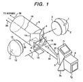
- Fig. 1 is a perspective view showing the main components of an optical system of a liquid crystal projector according to the first embodiment of the invention.
- the liquid crystal projector in the embodiment uses two light sources, two mirrors, and two aperture diaphragms.
- the optical system of the liquid crystal projector in the embodiment uses three liquid crystal panels and a dichroic prism for separating a light into lights of the three primary colors and synthesizing them.
- descriptions of the dichroic prism and the separating and synthesizing operations of the three primary colors are omitted with reference to Figs. 1 and 3. They will be described in detail with reference to Fig. 4.
- two metal halide lamps 1 and 11 as light sources and condenser reflectors 2 and 12 are arranged so as to face each other.
- Mirrors 4 and 14 and aperture diaphragms 8 and 18 are adjacently arranged, respectively, on a focal plane of a projection lens 9.
- the first mirror 4 corresponding to the first metal halide lamp 1 is arranged at the upper right of the focal plane of the projection lens 9.
- the first aperture diaphragm 8 is disposed at the lower left of the focal plane.
- the second mirror 14 corresponding to the second metal halide lamp 11 is arranged at the upper left of the focal plane and the second aperture diaphragm 18 is disposed at the lower right.
- the optical system of the embodiment has the structure such that two mirrors are adjacently arranged in the upper half of the focal plane and two aperture diaphragms are adjacently arranged in the lower half of the focal plane.
- One set of the mirror and the aperture diaphragm is arranged on an oblique line and another set of the mirror and the aperture diaphragm is arranged on another oblique line.
- the oblique lines perpendicularly cross each other in an X shape by using an optical axis 19 as a center.
- Each of the mirrors 4 and 14 has a rectangle shape in which the ratio of the length of the sides is (1 : 1.4). It looks like an almost square when it is seen from the front of the focal plane.
- a shielding plate 15 for the aperture diaphragm, which is positioned on the lower side of the first aperture diaphragm 8 is turned up around the lower side as a center to close the first aperture diaphragm 8 when only the second metal halide lamp 11 is turned on.
- Fig. 2 is a front view of a focal plane 10 of the projection lens 9 of the embodiment.
- the valid radius of the focal plane 10 of the projection lens 9 is 22 mm.
- the F-number of the projection lens 9 is approximately F2.8.
- each of the aperture diaphragms 8 and 18 has a shape obtained by notching a part of a circle which has the radius of 11 mm.
- each aperture diaphragm is about 330 mm 2 and the effective F-number for the projection lens 9 is about F5.9. Consequently, the aperture diaphragms have the valid area of about total 44% for the area of the focal plane of the projection lens in the optical system. It can be considered that the valid F-number of the projection lens of the optical system is about F4.2 by combining two aperture diaphragms.
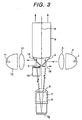
- Fig. 3 is a top view of the optical system of the embodiment. As shown in Fig. 3, each of the mirrors 4 and 14 of the optical system of the embodiment is arranged at about 46 degrees to the optical axis 19 of the projection lens 9. The aperture diaphragms 8 and 18 positioned below the mirrors are arranged vertically with respect to the optical axis 19 of the projection lens 9 as a center.
- Fig. 4 is a side view of the optical system of the embodiment.
- the metal halide lamps 1 and 11 and the condenser reflectors 2 and 12, which are disposed as if they overlap with the mirrors 4 and 14 when they are seen from the side, are omitted.
- a dichroic prism 6 is constructed by three prisms and separates a white light coming from the light source into lights of the three primary colors by dichroic films each of which reflects only a light having a specified wavelength.
- Reflecting and scattering type liquid crystal panels 7r, 7b, and 7g which correspond to red, blue, and green lights, respectively, are attached onto the top face, under face, and rear face of the dichroic prism 6.
- An illumination light 31 emitted from the metal halide lamp 1 as a first light source is reflected by the condenser reflector 2.
- the light 31 is condensed via the condenser lens 3 onto the first mirror 4 positioning at the upper right of the focal plane of the projection lens 9 and is reflected.
- the light 31 enters the dichroic prism 6 via a plane-convex lens 5.
- the illumination light 31 is separated into a red light 32r, a blue light 32b, and a green light 32g by the dichroic prism 6.
- the lights 32r, 32b, and 32g are modulated by the reflecting and scattering type liquid crystal panels 7r, 7b, and 7g into image lights, respectively. Consequently, a red image light 33r, a blue image light 33b, and a green image light 33g are reflected.
- the image lights 33r, 33b, and 33g are photocolorsynthesized by the dichroic prism 6, thereby deriving an outgoing image light 34.
- the outgoing image light 34 enters the projection lens 9 via the plane-convex lens 5 and the first aperture diaphragm 8 which is positioned at the lower left of the focal plane 10 of the projection lens 9 and is enlargedly projected onto a screen (not shown).
- An illumination light 35 emitted from the metal halide lamp 11 as a second light source is condensed onto the second mirror 14 via the condenser reflector 12 and the condenser lens 13 in a manner similar to the light emitted from the first light source. After being reflected by the mirror 14, the light 35 enters the dichroic prism 6 via the plane-convex lens 5.
- the illumination light 35 is separated by the dichroic prism 6 into a red light 36r, a blue light 36b, and a green light 36g.
- the lights 36r, 36b, and 36g are modulated to image lights 37r, 37b, and 37g by the reflective and scattering type liquid crystal panels 7r, 7b, and 7g, respectively. After that, the image lights 37r, 37b, and 37g are photocolorsynthesized by the dichroic prism 6, thereby deriving an outgoing image light 38.
- the outgoing image light 38 enters the projection lens 9 through the plane-convex lens 5 and the second aperture diaphragm 18 and is projected onto the screen (not shown).
- the outgoing image lights 34 and 38 of different light sources pass through different aperture diaphragms, they are reflected at the same position on the liquid crystal panel and pass through the same projection lens. Consequently, they are completely overlapped each other on the screen.
- the F-number of each aperture diaphragm is F5.9, an image having the same brightness and contrast as that of the optical system which has the aperture diaphragm of F4.2 for the projection lens of F2.8 can be actually obtained.
- the first metal halide lamp 1 shown in Fig. 1 is not turned on, only the second metal halide lamp 11 is turned on, and the first aperture diaphragm 8 is closed by the shielding plate 15. In this manner, the area of the aperture diaphragm is reduced to the half and the valid F-number for the projection lens is increased from F4.2 to about F5.9, thereby improving the contrast.
- Such an optical system was produced experimentally. When only second lamp is turned on and the first aperture diaphragm is closed, although the brightness becomes the half as compared with a case where two lamps are turned on, the contrast is improved to about the double.
- the mirrors and aperture diaphragms are effectively arranged for the projection lens.
- the effective area of the aperture diaphragm for the focal plane of the projection lens becomes about 44%.
- the projection lens is further miniaturized and lightened and still a bright image can be obtained.
- a high-quality image having high contrast which is always effective both in dark and light rooms can be provided.
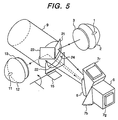
- Fig. 5 is a perspective view showing an optical system of a liquid crystal projector of the embodiment.
- the optical system of the second embodiment has the same structure as that of the optical system of the first embodiment except the shape of the aperture diaphragm. Elements similar to those in the first embodiment are designated by the same reference numerals and their descriptions are omitted here.
- Fig. 6 is a front view of the focal plane 10 of the projection lens in the embodiment.
- the shape of each of a first mirror 21 and a second mirror 23 is almost a square when it is seen from the front of the focal plane 10.
- a first aperture diaphragm 22 and a second aperture diaphragm 24 each having a shape of a quarter of a circle are adjacent each other.
- the effective F-number of the aperture diaphragm of a semicircle which is a shape when both of the aperture diaphragms 22 and 24 are combined is F4.0.
- the two aperture diaphragms 22 and 24 are completely combined and have a shape of one semicircular aperture diaphragm. Attention is paid to transmission paths of illuminations lights which are not diffused but are normally reflected by the liquid crystal panel.
- the illumination light 35 which is irradiated from the second metal halide lamp 11 and is reflected by the second mirror 23, is reflected by the liquid crystal panel.
- the light 35 passes through only the second aperture diaphragm 24 in the semicircular aperture diaphragm. Therefore, it can be considered that the functions of the two aperture diaphragms are completely independent, and although they are adjacent each other, each of them is independent.
- the liquid crystal projector of the second embodiment has effects such that the projection lens can be miniaturized and the compact optical system by which a bright image is obtained is realized.
- the contrast of the image is lower than that of the first embodiment, but the image is brighter.
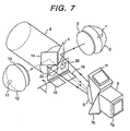
- Fig. 7 is a perspective view of an optical system of the embodiment.
- the structure of the optical system of the third embodiment is almost the same as that of the first embodiment except the shape of the aperture diaphragm and the number of shielding plates for aperture diaphragms (two in the third embodiment).
- Elements similar to those in the first embodiment are designated by the same reference numerals and their descriptions are omitted here.
- the size of a first aperture diaphragm 25 and that of a second aperture diaphragm 26 are different.
- the shape and area of the first aperture diaphragm 25 are the same as those of the first aperture diaphragm 8 of the first embodiment.
- the second aperture diaphragm 26 has a shape of a circle having the diameter of about 7 mm and has the almost half of the area of the first aperture diaphragm 25.
- the effective F-number is about F8.3.
- a shielding plate 16 to close the second aperture diaphragm 26 is arranged in addition to the shielding plate 15 which closes the first aperture diaphragm 25.
- the area of the second aperture diaphragm is the half of that of the first aperture diaphragm. Consequently, when only the second metal halide lamp is turned on, the brightness of the image is reduced to the half of a case when only the first metal halide lamp is turned on. The contrast of the image is improved to about 1.7 times.
- the liquid crystal projector of the embodiment can be used in three modes with respect to the brightness and contrast.
- the three modes are; a mode in which two lamps are turned on, a mode in which only the first lamp is turned on, and a mode in which only the second lamp is turned.
- the aperture diaphragms are efficiently arranged for the focal plane of the projection lens and the projection lens can be miniaturized and lightened.
- the brightness and the contrast of the image can be set in three modes in the embodiment, the fine setting according to the environment can be realized.
- the aperture diaphragm has the circular shape or the shape obtained by notching a part of the circle in the embodiments
- the area and shape of the aperture diaphragm differ according to the brightness of the image of the liquid crystal projector set, the degree of the contrast, the kind of the lamp of the light source (halogen lamp, metal halide lamp, xenon lamp, or the like), the shape of the condenser reflector, and the shape of the condenser lens.
- the areas and shapes of the aperture diaphragm included in the invention are not limited to those described in the embodiments, but a polygon, a corner-rounded square, a composite shape obtained by overlapping a number of circles or rectangles, or the like can be also used.
- the projection lens can be miniaturized and lightened while keeping the sufficient brightness of the image.
- the entire liquid crystal projector set can be consequently miniaturized and lightened.
- the light emitting unit of the lamp of the light source it is unnecessary to miniaturize the light emitting unit of the lamp of the light source and the light source is long-lasting and stable.
- the bright image and the current-saving high-contrast image can be easily switched in the same liquid crystal projector set, so that the image according to the environment can be provided.
- Fig. 12 is a top view showing the main components of an optical system of a liquid crystal projector according to the fourth embodiment of the invention.
- a metal halide lamp 101 as a light source is arranged right at the side of a projection lens 109.
- An exhaust fan 111 is arranged in the same direction of the projecting direction of the light from the projection lens for a lamp house 110 and an exhaust port 112 is arranged on the front face of the set.
- Fig. 13 is a side view of the optical system of the liquid crystal projector of the embodiment.
- the projection lens 109 and a mirror 104 which are positioned behind the lamp house 110 and a reflecting mirror 103 are shown by broken lines.
- a dichroic prism 106 is constructed by three prisms and separates a white light emitted from the light source into the three primary colors of red, blue, and green.
- Reflective type liquid crystal panels 107r, 107b, and 107g are attached onto the top face, under face, and rear face of the dichroic prism 106.
- An illumination light 141 emitted from the metal halide lamp 101 is reflected by a condenser reflector 102 which transmits infrared and ultraviolet rays.
- the optical path is moved to an almost parallel one by the reflecting mirror 103 and the mirror 104.
- the light enters the dichroic prism 106 via a plane-convex lens 105.
- the illumination light 141 is separated into lights of the three primary colors of red, blue, and green by the dichroic prism 106.
- the lights enter the reflecting type liquid crystal panels 107r, 107b, and 107g, respectively, and are modulated to an image light 142. After that, the image light 142 is reflected and photocolorsynthesized by the dichroic prism 106.
- the photocolorsynthesized image light 142 passes through the plane-convex lens 105 and enters the projection lens 109 via the aperture diaphragm 107.
- the light becomes an outgoing image light 144 which is enlarged by the projection lens and is projected from an outgoing plane of the projection lens.
- Infrared and ultraviolet rays 143 emitted from the metal halide lamp 101 transmit the condenser reflector 102. They are absorbed by the inner wall of the lamp house 110 and changed into heat. The heat stuffed in the lamp house is discharged from the exhaust port 112 by the exhaust fan 111.
- the exhaust 113 Since the exhaust 113 is discharged in the almost same direction as the outgoing image light 144 in the liquid crystal projector of the embodiment, the exhaust 113 is not discharged toward the operator or observer of the image who stays by avoiding the outgoing image light 144 and the peripheral equipment.
- the hot air stuffed in the lamp house 110 is promptly discharged forward and the dichroic prism 106 is arranged away from the light source. Consequently, the liquid crystal panels 107r, 107b, and 107g are not easily influenced by the heat of the light source and deterioration of the picture quality due to the heat can be avoided.
- the liquid crystal projector in the embodiment by arranging the exhaust port from which the heat in the lamp house is discharged on the front face of the set, the operator of the liquid crystal projector, the exhaust is not discharged toward the observer of the image, and the peripheral equipment such as an image generating source.
- the light source can be arranged away from the liquid crystal panel in the set.
- the set can be miniaturized while suppressing the deterioration of the picture quality of the liquid crystal panel caused by the increase in temperature.
- Fig. 14 is a top view of an optical system of a liquid crystal projector according to the embodiment.
- the structure of the optical system of the embodiment is the same as that of the fourth embodiment except that two metal halide lamps are used as a light source. Elements similar to those in the fourth embodiment are designated by the same reference numerals and their descriptions are omitted here.
- two metal halide lamps 101 are arranged on the right and left sides of the projection lens 109.
- Two exhaust ports are symmetrically arranged on the right and left sides of the projection lens 109 on the front face of the set.
- the exhaust ports from which heat in lamp houses are discharged can be also arranged on the front face of the set in the fifth embodiment, so that the operator or the peripheral equipment is not exposed by the exhaust.
- the light source is arranged away from the liquid crystal panel in the set, so that the set can be miniaturized while suppressing the deterioration of the picture quality of the liquid crystal panel caused by the increase in temperature.
- the exhaust is not discharged toward the operator of the liquid crystal projector or the observer of the image, so that the image can be pleasantly observed.
- the light source as a largest light generating unit can be arranged away from the liquid crystal panel which is easily influenced by heat in the set, so that the deterioration of the image due to increase in temperature can be suppressed. Since the influence of heat is reduced, the elements can be closely arranged. Thus, the set can be compactly produced.
Landscapes
- Engineering & Computer Science (AREA)
- Multimedia (AREA)
- Signal Processing (AREA)
- Liquid Crystal (AREA)
- Projection Apparatus (AREA)
Claims (8)
- Projecteur d'affichage d'image, comportant :dans lequel le premier diaphragme d'ouverture (8) et le premier petit miroir (4), formant un premier ensemble, sont positionnés sur une première ligne oblique et le second diaphragme d'ouverture (18) et le second petit miroir (14), formant un second ensemble, sont positionnés sur une second ligne oblique, les lignes obliques se croisant l'une et l'autre sur un axe optique (19) de la lentille de projection (9) en tant que centre, de sorte que les trajets de propagation de lumière provenant des première et seconde sources lumineuses (1, 11), respectivement, coupent le plan focal de ladite lentille de projection à des positions adjacentes.deux sources lumineuses (1, 11), un panneau d'affichage d'image de type à réflexion (7r, 7b, 7g), une lentille de projection (9), deux petits miroirs (4, 14) chacun étant agencé dans un trajet optique entre une des sources lumineuses (1, 11) et ledit panneau d'affichage d'image de type à réflexion (7r, 7b, 7g) et ladite lentille de projection (9), deux diaphragmes d'ouverture (8, 18), dans lequelune lumière provenant des première et seconde sources lumineuses (1, 11) entre dans le panneau d'affichage d'image de type à réflexion (7r, 7b, 7g) sur le côté des sources lumineuses via les premier et second petits miroirs (4, 14), respectivement, est modulée par le panneau d'affichage d'image de type à réflexion (7r, 7b, 7g) en des première et seconde lumières d'image, respectivement, est réfléchie, de sorte que lesdites lumières d'image entrent dans la lentille de projection (9) à travers des premier et second diaphragmes d'ouverture (8, 18) sur le côté de lentille de projection, respectivement, et est projetée de manière agrandie sur un écran par la lentille de projection (9),
- Projecteur selon la revendication 1, dans lequel deux sources lumineuses (1, 11) sont utilisées, deux miroirs (4, 14) sont adjacents dans la direction verticale ou horizontale dans un plan focal de la lentille de projection (9) et occupent environ la moitié du plan focal de la lentille de projection (9), et deux diaphragmes d'ouverture (8, 18) sont agencés de manière adjacente dans la direction horizontale ou verticale sur le côté opposé aux miroirs (4, 14) par rapport à l'axe optique de la lentille de projection (9).
- Projecteur selon la revendication 1 ou 2, dans lequel des parties adjacentes des diaphragmes d'ouverture adjacents (8, 18) sont combinées, de manière à réaliser une longue forme dans la direction voisine.
- Projecteur selon l'une quelconque des revendications précédentes, dans lequel des formes ou tailles des diaphragmes d'ouverture (8, 18) sont différentes.
- Projecteur selon l'une quelconque des revendications précédentes, dans lequel la forme du diaphragme d'ouverture (8, 18) est pratiquement un quart de cercle et les diaphragmes d'ouverture combinés (8, 18) ont une forme pratiquement semi-circulaire.
- Projecteur selon l'une quelconque des revendications précédentes, dans lequel seules des sources lumineuses (1, 11) d'un nombre optionnel parmi des sources lumineuses fournies (1, 11) sont activées et un mécanisme pour fermer le diaphragme d'ouverture (8, 18) correspondant à une source lumineuse qui n'est pas activée est fourni.
- Projecteur selon l'une quelconque des revendications précédentes, dans lequel un port d'évacuation (112) à partir duquel une chaleur résiduelle provenant de la source lumineuse (1, 11) est déchargée, est positionné sur la face avant du projecteur, sur laquelle une face de sortie de lumière de la lentille de projection (9) est également positionnée, et une direction de décharge de l'évacuation est pratiquement la même qu'une direction de sortie de la lumière d'image.
- Projecteur selon l'une quelconque des revendications précédentes, dans lequel la source lumineuse (1, 11) est agencée pratiquement à proximité de la lentille de projection (9).
Applications Claiming Priority (6)
| Application Number | Priority Date | Filing Date | Title |
|---|---|---|---|
| JP29246095 | 1995-11-10 | ||
| JP292460/95 | 1995-11-10 | ||
| JP7292460A JPH09133967A (ja) | 1995-11-10 | 1995-11-10 | 液晶プロジェクタ |
| JP29245995 | 1995-11-10 | ||
| JP7292459A JPH09133974A (ja) | 1995-11-10 | 1995-11-10 | 液晶プロジェクタ |
| JP292459/95 | 1995-11-10 |
Publications (3)
| Publication Number | Publication Date |
|---|---|
| EP0773691A2 EP0773691A2 (fr) | 1997-05-14 |
| EP0773691A3 EP0773691A3 (fr) | 1997-12-29 |
| EP0773691B1 true EP0773691B1 (fr) | 2002-07-24 |
Family
ID=26558999
Family Applications (1)
| Application Number | Title | Priority Date | Filing Date |
|---|---|---|---|
| EP96117779A Expired - Lifetime EP0773691B1 (fr) | 1995-11-10 | 1996-11-06 | Projecteur à cristaux liquides |
Country Status (3)
| Country | Link |
|---|---|
| US (1) | US5743612A (fr) |
| EP (1) | EP0773691B1 (fr) |
| DE (1) | DE69622504T2 (fr) |
Families Citing this family (44)
| Publication number | Priority date | Publication date | Assignee | Title |
|---|---|---|---|---|
| JPH11505334A (ja) | 1995-05-11 | 1999-05-18 | ディジタル プロジェクション リミテッド | 投影装置 |
| US6109752A (en) * | 1996-08-26 | 2000-08-29 | Seiko Epson Corporation | Lighting device and projector |
| JP3374018B2 (ja) * | 1996-09-12 | 2003-02-04 | 松下電器産業株式会社 | 前面投射型液晶表示装置 |
| JPH11149061A (ja) * | 1997-09-12 | 1999-06-02 | Minolta Co Ltd | 光源装置および照明装置 |
| JP3637743B2 (ja) * | 1997-10-15 | 2005-04-13 | ソニー株式会社 | 投射型液晶表示装置 |
| JP3319996B2 (ja) * | 1997-10-20 | 2002-09-03 | 株式会社日立製作所 | 映像表示機構及び映像表示装置 |
| JPH11249012A (ja) | 1998-02-27 | 1999-09-17 | Minolta Co Ltd | プロジェクター光学系 |
| JP2000171901A (ja) * | 1998-09-28 | 2000-06-23 | Matsushita Electric Ind Co Ltd | 照明光学装置および投写型表示装置 |
| JP2000121929A (ja) | 1998-10-15 | 2000-04-28 | Minolta Co Ltd | ゴーストの影響の少ない撮像光学系 |
| US6215547B1 (en) | 1998-11-19 | 2001-04-10 | Eastman Kodak Company | Reflective liquid crystal modulator based printing system |
| JP2000180795A (ja) * | 1998-12-18 | 2000-06-30 | Nec Corp | プロジェクタ装置 |
| US6330018B1 (en) | 1999-12-22 | 2001-12-11 | Eastman Kodak Company | Method and apparatus for printing high resolution images using reflective LCD modulators |
| US6396530B1 (en) | 2000-06-12 | 2002-05-28 | Eastman Kodak Company | Method for improving exposure resolution using multiple exposures |
| US6407766B1 (en) | 2000-07-18 | 2002-06-18 | Eastman Kodak Company | Method and apparatus for printing to a photosensitive media using multiple spatial light modulators |
| US6646716B1 (en) | 2000-07-27 | 2003-11-11 | Eastman Kodak Company | Method and apparatus for printing multiple simultaneous images onto a photosensitive media |
| JP2002107826A (ja) * | 2000-09-27 | 2002-04-10 | Seiko Epson Corp | プロジェクタ |
| US6614462B1 (en) * | 2000-10-19 | 2003-09-02 | Eastman Kodak Company | Method and apparatus for printing high resolution images using reflective LCD modulators |
| US6930797B2 (en) * | 2001-02-27 | 2005-08-16 | Eastman Kodak Company | Method and apparatus for printing high resolution images using multiple reflective spatial light modulators |
| JP3484435B2 (ja) * | 2001-04-25 | 2004-01-06 | 松下電器産業株式会社 | 投写型表示装置 |
| US6980321B2 (en) | 2001-08-20 | 2005-12-27 | Eastman Kodak Company | Method and apparatus for printing high resolution images using multiple reflective spatial light modulators |
| US6980280B2 (en) * | 2001-10-12 | 2005-12-27 | Eastman Kodak Company | Two level image writer |
| GB2382880A (en) * | 2001-12-10 | 2003-06-11 | Wynne Willson Gottelier Ltd | Colour projector with movable colour filters and elliptical mask window |
| US6961194B2 (en) * | 2001-12-31 | 2005-11-01 | Texas Instruments Incorporated | Integrated TIR prism and lens element |
| EP1461962A1 (fr) * | 2002-01-07 | 2004-09-29 | 3M Innovative Properties Company | Diaphragmes d'ouverture pour composantes couleur dans un systeme d'affichage par projection |
| JP3880436B2 (ja) * | 2002-04-12 | 2007-02-14 | キヤノン株式会社 | 投写型画像表示装置 |
| JP3092509U (ja) * | 2002-09-02 | 2003-03-20 | 船井電機株式会社 | Dmdを用いた画像表示プロジェクタ |
| US7201498B2 (en) * | 2002-10-10 | 2007-04-10 | Matsushita Electric Industrial Co., Ltd. | Lighting apparatus |
| US7008065B2 (en) | 2003-01-07 | 2006-03-07 | 3M Innovative Properties Company | Color component aperture stops in projection display system |
| US7369268B2 (en) * | 2003-01-14 | 2008-05-06 | Eastman Kodak Company | Light source using large area LEDs |
| EP1471746A3 (fr) * | 2003-03-31 | 2006-07-12 | Barco N.V. | Appareil de projection et système de source lumineuse à lampe pour un tel appareil |
| US7196849B2 (en) * | 2003-05-22 | 2007-03-27 | Optical Research Associates | Apparatus and methods for illuminating optical systems |
| WO2004106982A2 (fr) * | 2003-05-22 | 2004-12-09 | Optical Research Associates | Modeles de combineurs optiques et visiocasques |
| WO2004106983A2 (fr) * | 2003-05-22 | 2004-12-09 | Optical Research Associates | Eclairage dans des systemes optiques |
| JP4731938B2 (ja) * | 2004-05-13 | 2011-07-27 | 株式会社リコー | 画像表示装置・投射光学系 |
| US7450310B2 (en) * | 2005-05-03 | 2008-11-11 | Optical Research Associates | Head mounted display devices |
| US7542209B2 (en) | 2004-09-01 | 2009-06-02 | Optical Research Associates | Compact head mounted display devices with tilted/decentered lens element |
| EP1850172B1 (fr) * | 2005-04-15 | 2013-05-29 | Mitsubishi Electric Corporation | Dispositif d'affichage de type par projection |
| TWI303010B (en) * | 2005-05-19 | 2008-11-11 | Benq Corp | Projector having a detachable light module |
| TWI285785B (en) * | 2005-11-23 | 2007-08-21 | Benq Corp | Light source apparatus for optical projection system |
| DE102005061182B4 (de) * | 2005-12-21 | 2020-03-19 | Carl Zeiss Jena Gmbh | Beleuchtungseinrichtung zur Farbbildprojektion |
| JP5334494B2 (ja) * | 2008-08-20 | 2013-11-06 | 三菱電機株式会社 | 投写型表示装置 |
| JP6007756B2 (ja) | 2012-11-29 | 2016-10-12 | セイコーエプソン株式会社 | プロジェクター |
| JP6127533B2 (ja) * | 2013-01-22 | 2017-05-17 | セイコーエプソン株式会社 | プロジェクター |
| JP6421930B2 (ja) | 2014-01-09 | 2018-11-14 | パナソニックIpマネジメント株式会社 | 照明装置及び投写型映像表示装置 |
Citations (5)
| Publication number | Priority date | Publication date | Assignee | Title |
|---|---|---|---|---|
| EP0490171A2 (fr) * | 1990-11-28 | 1992-06-17 | Canon Kabushiki Kaisha | Dispositif à cristal liquide du type diffusant |
| EP0615388A2 (fr) * | 1993-02-18 | 1994-09-14 | Ag Technology Co. Ltd. | Appareil pour la projection optique en couleur avec affichage à cristaux liquides |
| JPH06281909A (ja) * | 1993-03-26 | 1994-10-07 | A G Technol Kk | 液晶光学装置及びそれを用いた照明装置 |
| US5382790A (en) * | 1990-07-24 | 1995-01-17 | Deutsche Thomson-Brandt Gmbh | Illumination device having beam splitting polarization means |
| US5386250A (en) * | 1993-08-09 | 1995-01-31 | Philips Electronics North America Corp. | Two-source illumination system |
Family Cites Families (14)
| Publication number | Priority date | Publication date | Assignee | Title |
|---|---|---|---|---|
| US4552441A (en) * | 1984-06-29 | 1985-11-12 | International Business Machines Corporation | Color display from a single light valve |
| US4925295A (en) * | 1986-03-17 | 1990-05-15 | Casio Computer Co., Ltd. | Projection display apparatus |
| JPH02130542A (ja) * | 1988-11-11 | 1990-05-18 | Kawasaki Heavy Ind Ltd | 画像投影装置 |
| JPH0468689A (ja) * | 1990-07-03 | 1992-03-04 | Matsushita Electric Ind Co Ltd | 液晶プロジェクター |
| JP2671261B2 (ja) * | 1990-11-28 | 1997-10-29 | キヤノン株式会社 | 液晶デバイス及び投写型液晶表示装置 |
| US5287132A (en) * | 1991-02-16 | 1994-02-15 | Fuji Photo Film Co., Ltd. | Video projector |
| EP0504813B1 (fr) * | 1991-03-19 | 1998-03-04 | Hitachi, Ltd. | Méthode de projection d'image obtenue avec des panneaux à cristaux liquides et dispositif d'affichage pour la mettre en oeuvre |
| JP3158484B2 (ja) * | 1991-05-23 | 2001-04-23 | 日本電信電話株式会社 | 投射型表示装置 |
| US5313234A (en) * | 1991-07-26 | 1994-05-17 | Sayett Group, Inc. | Liquid crystal projector |
| JPH05196892A (ja) * | 1992-01-21 | 1993-08-06 | Canon Inc | 偏光照明装置及び該偏光照明装置を用いた投写型表示装置 |
| US5648860A (en) * | 1992-10-09 | 1997-07-15 | Ag Technology Co., Ltd. | Projection type color liquid crystal optical apparatus |
| US5379083A (en) * | 1994-02-15 | 1995-01-03 | Raychem Corporation | Projector |
| EP0722253A3 (fr) * | 1995-01-10 | 1996-10-30 | Ibm | Arrangements pour des dispositifs d'affichage par projection utilisant des valves optiques en réflexion |
| US5621486A (en) * | 1995-06-22 | 1997-04-15 | International Business Machines Corporation | Efficient optical system for a high resolution projection display employing reflection light valves |
-
1996
- 1996-11-04 US US08/743,644 patent/US5743612A/en not_active Expired - Fee Related
- 1996-11-06 DE DE69622504T patent/DE69622504T2/de not_active Expired - Fee Related
- 1996-11-06 EP EP96117779A patent/EP0773691B1/fr not_active Expired - Lifetime
Patent Citations (5)
| Publication number | Priority date | Publication date | Assignee | Title |
|---|---|---|---|---|
| US5382790A (en) * | 1990-07-24 | 1995-01-17 | Deutsche Thomson-Brandt Gmbh | Illumination device having beam splitting polarization means |
| EP0490171A2 (fr) * | 1990-11-28 | 1992-06-17 | Canon Kabushiki Kaisha | Dispositif à cristal liquide du type diffusant |
| EP0615388A2 (fr) * | 1993-02-18 | 1994-09-14 | Ag Technology Co. Ltd. | Appareil pour la projection optique en couleur avec affichage à cristaux liquides |
| JPH06281909A (ja) * | 1993-03-26 | 1994-10-07 | A G Technol Kk | 液晶光学装置及びそれを用いた照明装置 |
| US5386250A (en) * | 1993-08-09 | 1995-01-31 | Philips Electronics North America Corp. | Two-source illumination system |
Non-Patent Citations (1)
| Title |
|---|
| PATENT ABSTRACT OF JAPAN, vol.95, no. 1, 28 February 1995 & JP H06 281909 A (A G TECHNOL KK), 7 October 1994 * |
Also Published As
| Publication number | Publication date |
|---|---|
| DE69622504T2 (de) | 2003-03-27 |
| DE69622504D1 (de) | 2002-08-29 |
| EP0773691A2 (fr) | 1997-05-14 |
| US5743612A (en) | 1998-04-28 |
| EP0773691A3 (fr) | 1997-12-29 |
Similar Documents
| Publication | Publication Date | Title |
|---|---|---|
| EP0773691B1 (fr) | Projecteur à cristaux liquides | |
| JP3635867B2 (ja) | 投射型液晶表示装置 | |
| US5777789A (en) | Efficient optical system for a high resolution projection display employing reflection light valves | |
| US5621486A (en) | Efficient optical system for a high resolution projection display employing reflection light valves | |
| EP0734184B1 (fr) | Système optique efficace pour un écran de projection haute résolution employant des valves de lumière à réflexion | |
| US6174060B1 (en) | Projection-type display apparatus having polarized beam splitters and an illuminating device | |
| JP2505758B2 (ja) | ビデオ・プロジエクシヨン装置 | |
| EP0405953B1 (fr) | Appareil-source de lumière pour séparer la lumière blanche en composantes de différentes couleurs | |
| KR100441506B1 (ko) | 영상투사장치 | |
| US5617152A (en) | Projector system for video and computer generated information | |
| JPH11119151A (ja) | 光源装置および投影装置 | |
| JP3335885B2 (ja) | 偏光照明装置、および投写型液晶表示装置 | |
| EP0631434A1 (fr) | Projecteur | |
| JP2001222002A (ja) | 液晶プロジェクタ装置 | |
| JPH09133974A (ja) | 液晶プロジェクタ | |
| JP3701830B2 (ja) | 光学装置及びそれを用いた映像表示装置 | |
| JP2001183764A (ja) | 液晶プロジェクタ装置 | |
| JP2000010044A (ja) | 液晶プロジェクタ | |
| KR100359728B1 (ko) | 액정 프로젝터의 광학 장치 | |
| JP3550261B2 (ja) | 液晶プロジェクタ | |
| KR100236907B1 (ko) | 3패널 lcd 프로젝터 | |
| JPH02275933A (ja) | 液晶プロジェクタ | |
| JP2532375B2 (ja) | カラ−液晶プロジエクタ | |
| JPH1164792A (ja) | 照明装置および画像投影装置 | |
| JP2845213B2 (ja) | 液晶プロジェクタ |
Legal Events
| Date | Code | Title | Description |
|---|---|---|---|
| PUAI | Public reference made under article 153(3) epc to a published international application that has entered the european phase |
Free format text: ORIGINAL CODE: 0009012 |
|
| 17P | Request for examination filed |
Effective date: 19961106 |
|
| AK | Designated contracting states |
Kind code of ref document: A2 Designated state(s): DE FR GB |
|
| PUAL | Search report despatched |
Free format text: ORIGINAL CODE: 0009013 |
|
| AK | Designated contracting states |
Kind code of ref document: A3 Designated state(s): DE FR GB |
|
| 17Q | First examination report despatched |
Effective date: 20000210 |
|
| GRAG | Despatch of communication of intention to grant |
Free format text: ORIGINAL CODE: EPIDOS AGRA |
|
| GRAG | Despatch of communication of intention to grant |
Free format text: ORIGINAL CODE: EPIDOS AGRA |
|
| GRAH | Despatch of communication of intention to grant a patent |
Free format text: ORIGINAL CODE: EPIDOS IGRA |
|
| GRAH | Despatch of communication of intention to grant a patent |
Free format text: ORIGINAL CODE: EPIDOS IGRA |
|
| GRAA | (expected) grant |
Free format text: ORIGINAL CODE: 0009210 |
|
| AK | Designated contracting states |
Kind code of ref document: B1 Designated state(s): DE FR GB |
|
| REG | Reference to a national code |
Ref country code: GB Ref legal event code: FG4D |
|
| REF | Corresponds to: |
Ref document number: 69622504 Country of ref document: DE Date of ref document: 20020829 |
|
| ET | Fr: translation filed | ||
| PLBE | No opposition filed within time limit |
Free format text: ORIGINAL CODE: 0009261 |
|
| STAA | Information on the status of an ep patent application or granted ep patent |
Free format text: STATUS: NO OPPOSITION FILED WITHIN TIME LIMIT |
|
| 26N | No opposition filed |
Effective date: 20030425 |
|
| PGFP | Annual fee paid to national office [announced via postgrant information from national office to epo] |
Ref country code: FR Payment date: 20051024 Year of fee payment: 10 |
|
| PGFP | Annual fee paid to national office [announced via postgrant information from national office to epo] |
Ref country code: GB Payment date: 20051109 Year of fee payment: 10 |
|
| PGFP | Annual fee paid to national office [announced via postgrant information from national office to epo] |
Ref country code: DE Payment date: 20051202 Year of fee payment: 10 |
|
| PG25 | Lapsed in a contracting state [announced via postgrant information from national office to epo] |
Ref country code: DE Free format text: LAPSE BECAUSE OF NON-PAYMENT OF DUE FEES Effective date: 20070601 |
|
| GBPC | Gb: european patent ceased through non-payment of renewal fee |
Effective date: 20061106 |
|
| REG | Reference to a national code |
Ref country code: FR Ref legal event code: ST Effective date: 20070731 |
|
| PG25 | Lapsed in a contracting state [announced via postgrant information from national office to epo] |
Ref country code: GB Free format text: LAPSE BECAUSE OF NON-PAYMENT OF DUE FEES Effective date: 20061106 |
|
| PG25 | Lapsed in a contracting state [announced via postgrant information from national office to epo] |
Ref country code: FR Free format text: LAPSE BECAUSE OF NON-PAYMENT OF DUE FEES Effective date: 20061130 |