EP0773116A1 - Bandage pneumatique pour véhicule motorisé, pourvu d'un profil de bande de roulement particulièrement adapaté au roulage sur surfaces couvertes de neige - Google Patents
Bandage pneumatique pour véhicule motorisé, pourvu d'un profil de bande de roulement particulièrement adapaté au roulage sur surfaces couvertes de neige Download PDFInfo
- Publication number
- EP0773116A1 EP0773116A1 EP96117948A EP96117948A EP0773116A1 EP 0773116 A1 EP0773116 A1 EP 0773116A1 EP 96117948 A EP96117948 A EP 96117948A EP 96117948 A EP96117948 A EP 96117948A EP 0773116 A1 EP0773116 A1 EP 0773116A1
- Authority
- EP
- European Patent Office
- Prior art keywords
- pneumatic tyre
- tyre according
- circumferential
- grooves
- tread band
- Prior art date
- Legal status (The legal status is an assumption and is not a legal conclusion. Google has not performed a legal analysis and makes no representation as to the accuracy of the status listed.)
- Granted
Links
- 238000005096 rolling process Methods 0.000 claims abstract description 27
- 238000000926 separation method Methods 0.000 claims abstract description 5
- 230000003542 behavioural effect Effects 0.000 description 5
- 230000000694 effects Effects 0.000 description 5
- 230000015572 biosynthetic process Effects 0.000 description 1
- 230000002860 competitive effect Effects 0.000 description 1
- 230000003247 decreasing effect Effects 0.000 description 1
- 230000005489 elastic deformation Effects 0.000 description 1
- 229920001971 elastomer Polymers 0.000 description 1
- 239000000806 elastomer Substances 0.000 description 1
- 238000011156 evaluation Methods 0.000 description 1
- 230000000670 limiting effect Effects 0.000 description 1
- 230000014759 maintenance of location Effects 0.000 description 1
- 239000000463 material Substances 0.000 description 1
- 230000013011 mating Effects 0.000 description 1
- 238000012986 modification Methods 0.000 description 1
- 230000004048 modification Effects 0.000 description 1
- 238000012856 packing Methods 0.000 description 1
- 230000000750 progressive effect Effects 0.000 description 1
- 230000002829 reductive effect Effects 0.000 description 1
- 230000000717 retained effect Effects 0.000 description 1
- 230000006641 stabilisation Effects 0.000 description 1
- 238000011105 stabilization Methods 0.000 description 1
- XLYOFNOQVPJJNP-UHFFFAOYSA-N water Substances O XLYOFNOQVPJJNP-UHFFFAOYSA-N 0.000 description 1
Images
Classifications
-
- B—PERFORMING OPERATIONS; TRANSPORTING
- B60—VEHICLES IN GENERAL
- B60C—VEHICLE TYRES; TYRE INFLATION; TYRE CHANGING; CONNECTING VALVES TO INFLATABLE ELASTIC BODIES IN GENERAL; DEVICES OR ARRANGEMENTS RELATED TO TYRES
- B60C11/00—Tyre tread bands; Tread patterns; Anti-skid inserts
- B60C11/03—Tread patterns
- B60C11/13—Tread patterns characterised by the groove cross-section, e.g. for buttressing or preventing stone-trapping
- B60C11/1369—Tie bars for linking block elements and bridging the groove
-
- B—PERFORMING OPERATIONS; TRANSPORTING
- B60—VEHICLES IN GENERAL
- B60C—VEHICLE TYRES; TYRE INFLATION; TYRE CHANGING; CONNECTING VALVES TO INFLATABLE ELASTIC BODIES IN GENERAL; DEVICES OR ARRANGEMENTS RELATED TO TYRES
- B60C11/00—Tyre tread bands; Tread patterns; Anti-skid inserts
-
- B—PERFORMING OPERATIONS; TRANSPORTING
- B60—VEHICLES IN GENERAL
- B60C—VEHICLE TYRES; TYRE INFLATION; TYRE CHANGING; CONNECTING VALVES TO INFLATABLE ELASTIC BODIES IN GENERAL; DEVICES OR ARRANGEMENTS RELATED TO TYRES
- B60C11/00—Tyre tread bands; Tread patterns; Anti-skid inserts
- B60C11/03—Tread patterns
- B60C11/0306—Patterns comprising block rows or discontinuous ribs
- B60C11/0309—Patterns comprising block rows or discontinuous ribs further characterised by the groove cross-section
-
- B—PERFORMING OPERATIONS; TRANSPORTING
- B60—VEHICLES IN GENERAL
- B60C—VEHICLE TYRES; TYRE INFLATION; TYRE CHANGING; CONNECTING VALVES TO INFLATABLE ELASTIC BODIES IN GENERAL; DEVICES OR ARRANGEMENTS RELATED TO TYRES
- B60C11/00—Tyre tread bands; Tread patterns; Anti-skid inserts
- B60C11/03—Tread patterns
- B60C11/11—Tread patterns in which the raised area of the pattern consists only of isolated elements, e.g. blocks
-
- B—PERFORMING OPERATIONS; TRANSPORTING
- B60—VEHICLES IN GENERAL
- B60C—VEHICLE TYRES; TYRE INFLATION; TYRE CHANGING; CONNECTING VALVES TO INFLATABLE ELASTIC BODIES IN GENERAL; DEVICES OR ARRANGEMENTS RELATED TO TYRES
- B60C11/00—Tyre tread bands; Tread patterns; Anti-skid inserts
- B60C11/03—Tread patterns
- B60C11/12—Tread patterns characterised by the use of narrow slits or incisions, e.g. sipes
- B60C11/1204—Tread patterns characterised by the use of narrow slits or incisions, e.g. sipes with special shape of the sipe
- B60C2011/1213—Tread patterns characterised by the use of narrow slits or incisions, e.g. sipes with special shape of the sipe sinusoidal or zigzag at the tread surface
-
- Y—GENERAL TAGGING OF NEW TECHNOLOGICAL DEVELOPMENTS; GENERAL TAGGING OF CROSS-SECTIONAL TECHNOLOGIES SPANNING OVER SEVERAL SECTIONS OF THE IPC; TECHNICAL SUBJECTS COVERED BY FORMER USPC CROSS-REFERENCE ART COLLECTIONS [XRACs] AND DIGESTS
- Y10—TECHNICAL SUBJECTS COVERED BY FORMER USPC
- Y10S—TECHNICAL SUBJECTS COVERED BY FORMER USPC CROSS-REFERENCE ART COLLECTIONS [XRACs] AND DIGESTS
- Y10S152/00—Resilient tires and wheels
- Y10S152/03—Slits in threads
Definitions
- the present invention relates to a pneumatic tyre for vehicle wheels provided with a tread pattern particularly appropriate for running on snow-covered road surfaces, comprising at least two series of transverse grooves disposed on opposite sides relative to an equatorial plane of the tyre and symmetrically converging at said equatorial plane; at least two circumferential grooves symmetrically spaced apart from the equatorial plane of the tyre and confining, together with the transverse grooves, one or more rows of centre blocks disposed symmetrically to the equatorial plane and at least two rows of shoulder blocks located on respectively opposite sides relative to the centre block rows.
- the invention refers to motor-vehicle pneumatic tyres of the so-called "winter" type.
- Said behavioural and operating features are achieved by forming appropriate circumferential and transverse grooves in the tread band, which grooves are suitably sized and oriented and give rise to the formation of blocks usually aligned in rows disposed consecutively side by side and extending circumferentially to the tyre.
- an indispensable detail for improving the behavioural running features of a tyre on a snow-covered road surface is the presence of appropriate "lamellae” or “fins” in the blocks, that is a thick series of narrow cuts or grooves small-sized in a circumferential direction, substantially oriented transversely of the rolling direction and substantially having the task of efficiently collecting and retaining the snow, since snow-on-snow friction is, as known, stronger than rubber-on-snow friction.
- a type of winter tyre which has been recently commercialized by the Applicant has a pair of circumferential straight-extending grooves in the tread band, which grooves are disposed symmetrically to the equatorial plane of the tyre and spaced apart by a distance substantially corresponding to half the overall width of the tread band.
- circumferential grooves are combined with two series of transverse grooves each extending with a gradually increasing inclination from the outer edge of the tread band until close to the equatorial plane.
- the transverse grooves of the two series are symmetrically converging at the equatorial plane of the tyre according to a given preferential rolling direction and have the respective vertices consecutively alternated with respect to each other along the perimetric extension of the tread band at the equatorial plane itself.
- the configuration of the transverse grooves is adapted to promote good traction qualities, by virtue of the mutual convergence of the grooves themselves in the rolling direction.
- the circumferential straight-extending grooves enable the water present in the ground-contacting area of the tyre to be efficiently eliminated during a running on a wet road surface, thereby preventing arising of the well known and dangerous aquaplane effect.
- the traction capability and, as a whole, the ride behaviour on a snow-covered road surface are assisted by the presence of a thick arrangement of fins on the blocks generated by the intersection between the longitudinal and transverse grooves and by appropriate straight extending hollows associated with the transverse grooves, in the space confined between the two circumferential grooves, each of said hollows extending in a circumferential direction over a short length starting from the respective transverse groove.
- the transverse grooves mutually converge according to a rolling direction assigned to the tread band.
- the distance between said longitudinal grooves preferably is included between 25% and 35% of the overall width of the tread band, measured between the opposite side edges of said band, and each of the oblique stretches of the circumferential grooves extends between two consecutive transverse grooves and defines respectively opposite circumferential edges of a centre block and a shoulder block, so that each of said centre and shoulder blocks has a corner projecting inwardly of the respective circumferential groove with respect to the opposite corner of the immediately following block.
- At least one grip hollow be associated with each of said transverse grooves, said hollow being of substantially trapezoidal shape and having an inner circumferential edge and an outer circumferential edge which respectively diverge preferably by an angle included between 3° and 15°, in a direction opposite to the rolling direction.
- each of said grip hollows has a maximum width included between 3 and 7 mm and extends across one of said transverse grooves at two contiguous centre blocks, with the respective inner circumferential edge substantially parallel to the circumferential direction of the tread band.
- a circumferential central cut extending in the equatorial plane to mutually separate two of said centre block rows.
- This central cut at least at one base portion thereof, has a width included between 2 and 4 mm, and generates two respectively opposite separation walls between each pair of centre blocks, each belonging to one of said centre rows, which walls are designed to come into mutual contact relation when the tread band is deformed against the roadway.
- each of said transverse grooves has an external portion confined between two of said shoulder blocks, in which portion a first and a second consecutive stretches are defined which converge in a direction opposite to the rolling direction.
- the first stretch, terminating at the side edge of the tread band, preferably has an inclination included between 1° and 10° to the axial direction of the tread band, whereas the second stretch communicating with the respective circumferential groove, has an inclination included between 8° and 16° to said axial direction.
- each of said transverse grooves is provided with a gradually increasing width, moving away from the equatorial plane.
- said second stretch communicating with the respective circumferential groove is of a width lower than that of the first stretch, terminating at the side edge of the tread band.
- Each of said transverse grooves further has an inner portion extending between two centre blocks in which a first stretch communicating with the respective circumferential groove and a second stretch extending close to the equatorial plane and having a lower width than the first stretch of said inner portion are defined, the first stretch of said inner portion preferably being of lower width than the second stretch of said outer portion.
- the second stretch of said inner portion is circumferentially offset in the rolling direction with respect to the first stretch.
- the oblique stretches forming said circumferential grooves are inclined to an angle included between 8° and 22° relative to the circumferential direction of the tread band and intersect the transverse grooves at an angle included between 80° and 110°.
- auxiliary hollows formed in the shoulder blocks at the convergence points between the first and second stretches of the outer portion of each transverse groove and preferably oriented parallelly to the oblique stretches of the circumferential grooves, of a lower depth than the respective transverse grooves.
- each shoulder block can be mutually interconnected by an auxiliary cut extending parallelly to the oblique stretches of the circumferential grooves and having a lower depth than the auxiliary hollows.
- the transverse grooves further have tapering end portions at the side edges of the tread band.
- Each of said centre and shoulder blocks also has fin-shaped cuts oriented substantially parallelly to said transverse grooves.
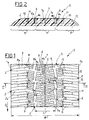
- a tread band for pneumatic tyres in particular adapted for running on snow-covered road surfaces according to the present invention has been generally identified by reference numeral 1; in particular this tread band is in the specific version for size 175/70 R 13.
- Said tyres have a carcass, preferably of the radial type, reinforced with a corresponding belt structure, (quite known in se and not of importance to the ends of the present invention) crownwise to which a tread band of appropriate elastomer material is arranged, which tread band is molded with a raised pattern and is intended for rolling contact on the ground.
- the tread band 1 has at least two series of transverse grooves, generally denoted by 2, disposed on opposite sides of the equatorial plane of the tyre on which the tread band 1 is mounted. This equatorial plane is denoted by line "X" in the accompanying drawings.
- the transverse grooves substantially have a course symmetrically converging at the equatorial plane itself according to a given rolling direction denoted by arrow "D" in Fig. 1, which has been previously assigned to the tyre.
- the tread band 1 further has at least two circumferential grooves, generally identified by 3, disposed simmetrically to the equatorial plane "X” and preferably spaced apart from each other by a measure “L” included between 25% and 35% of the overall width "W" of the tread band 1, measured between the opposite side edges 1a thereof.
- the circumferential grooves 3 together with the transverse grooves 2 define one or more rows of centre blocks 4, disposed symmetrically to the equatorial plane "X" and at least two rows of shoulder blocks 5 located on respectively opposite sides with respect to the centre blocks 4.
- each of the circumferential grooves 3 is defined by a sequence of stretches 3a oriented obliquely to the circumferential direction of the tyre.
- the oblique stretches 3a forming either of the circumferential grooves 3 symmetrically converge at the equatorial plane "X" in a direction opposite to the convergence direction of the transverse grooves 2, that is the rolling direction "D".
- the inclinations of the transverse grooves 2 and oblique stretches 3a of the longitudinal grooves 3 are such selected that the corners of the shoulder and centre blocks 5 and 4 generated by the intersection thereof have a summit angle included between 80° and 110°, so that they have an excellent resistance to wear.
- the inclination of the oblique stretches 3a of the circumferential grooves 3 to the circumferential direction is preferably included between 8° and 22°.
- each transverse groove 2 is respectively divided into an outer portion 8, confined between two shoulder blocks 5 and an inner portion 9 confined between two contiguous centre blocks 4.
- a first stretch 8a terminating at the side edge of the tread band 1 and a second stretch 8b, consecutive to the first one and terminating at the respective circumferential groove 3.
- the inner portion 9 of each transverse groove 2 has a first stretch 9a opening into the circumferential groove 3 and a second stretch 9b terminating at the equatorial plane "X".
- the transverse grooves 2 have a gradually increasing width moving away from the equatorial plane "X".
- the second stretch 8b of the outer portion 8 of each transverse groove 2 has a width preferably included between 4 and 9 mm and in any case lower than that of the first stretch 8a of the same outer portion 8 which is included between 5 and 11 mm.
- the width of the first stretch 9a of the inner portion of each transverse groove 2 is lower that that of the second stretch 8b of the outer portion 8, whereas the second stretch 9b of the inner portion 9 has a lower width than the first stretch 9a of the same inner portion.
- the second stretches 9b of the inner portions 9 are preferably provided to be offset in the rolling direction "D" with respect to the corresponding first stretches 9a.
- This angle is substantially constant at least over the whole extension of the inner portion 9 and preferably included between 8° and 16° with respect to the axial direction.
- the inclination of the second stretch 8b of the outer portion 8 has the same value as the inclination of stretches 9a, 9b of the inner portion 9.
- the first stretch 8a of the outer portion 8 of each transverse groove 2 instead has an inclination included between 1° and 10°, still with respect to the axial direction, facing away from that of the second stretch 8b of the same outer portion. In this manner, stretches 8a, 8b of the outer portion 8 mutually converge in a direction opposite to the rolling direction "D".
- the mutual arrangement of the longitudinal (3) and transverse (2) grooves is such that in the tread band 1 width a central area denoted by "A” in Fig. 2 and two side areas denoted by “B” are defined.
- the central area A is occupied by the centre blocks 4 and is specifically appropriate to enhance the traction capability features of the tyre, whereas the side areas "B" are entrusted with the task of ensuring good performance on braking, that is when the tangential stresses taking place between the tread band and the roadway are directed in the opposite way as compared with what happens on traction.
- each pair of transverse grooves 2 belonging to the same block pitch comes into contact with the roadway at the ground-contacting area, first by its own vertex which is immediately filled with snow. Progressive entering of snow along the remaining parts of the transverse grooves, as rolling goes on, causes the snow present at the above mentioned "V" vertex to become packed, so that, as a result, said snow is retained by the transverse grooves, to advantage of a good traction capability.
- grip hollows 6 of substantially trapezoidal form are also provided to be associated with the transverse grooves 2.
- Said hollows 6 each have an inner circumferential edge 6a and an outer circumferential edge 6b that respectively diverge according to an angle included between 3° and 15° in a direction opposite to the rolling direction "D".
- each grip hollow 6 which completely crosses the corresponding transverse groove 2 thereby extending at two contiguous centre blocks 4, is provided to have a maximum width, at its largest point, included between 3 and 7 mm and its inner circumferential edge 6a is oriented parallelly to the circumferential extension direction of the tread band.
- each grip hollow 6 On running, each grip hollow 6 reaches the ground contact area first by its narrower portion which is immediately filled with the snow present on the roadway. As rolling goes on, the larger end portion of the grip hollow 6 is filled with snow too and, by effect of the vertical load, said snow is forced into the hollow itself. So the snow which had already filled the narrower portion of the hollow is wedged between the mutually converging circumferential edges 6a and 6b and becomes therein packed.
- the grip hollows 6 appear to be capable of efficiently collecting and retaining the snow present on the roadway.
- the centre block 4 rows be mutually separated by at least one central circumferential cut 7 extending in the equatorial plane "X".
- This central cut at least in the lower area thereof, has a relatively reduced width, included, by way of example, between 2 and 4 mm, so that between each pair of side-by-side centre blocks 4 two separation walls 7a are generated which are adapted to come into mutual contact relation when, at the ground-contacting area, the tread band 1 is deformed against the roadway, thereby modifying its transverse profile from a starting convex configuration to a final flattened configuration.
- the central cut 7 performs the function of defining a pliability point in the tread band 1 so as to enable said band to be easily flattened against the roadway without causing elastic deformations in the remaining parts of the central area "A", in that said deformations would facilitate an undesired ejection of the snow entrapped in the grooves 2, 3 and grip hollows 6.
- the mutual mating of the opposite walls 7a further increases packing of the snow within the transverse grooves 2 and, when a vehicle is running both on a snow-covered roadway and on a wet or dry roadway, a structural stabilization of the tread band in the central area 6 is determined, to advantage of the directional features of the tyre.
- the longitudinal grooves 3 separate the central area "A" from the side areas "B" and the configuration of said grooves is susceptible of determining advantages both under running and bracking conditions.
- each oblique stretch 3a extends between two contiguous transverse grooves 2 and defines the opposite cirumferential edges of one of the centre blocks 4 and one of the shoulder blocks 5, respectively.
- each of the centre and shoulder blocks 4 and 5 has a corner 4a, 5a projecting inwardly of the respective circumferential groove 3 with respect to the opposite corner of the immediately following block.
- the projecting corners 4a of the centre blocks behave like teeth ensuring a grip on the snow on traction, whereas the projecting corners 5a of the shoulder blocks 5 produce the same effect on braking.
- first and second stretches 8a, 8b of the outer portion 8 of each transverse groove 2 have such an orientation that they converge in a direction opposite to the rolling direction "D", thereby forming an inverted-vertex "V", as compared with the one formed by the central portions 9 of the same grooves.
- the outer portions 8 furnish an efficient grip action on the snow, in particular during braking, that is when the tangential efforts transmitted by the tread band 1 on the roadway are in the opposite direction with respect to the case in which traction occurs.
- auxiliary opposite hollows 10 be provided, which are oriented substantially parallelly to the oblique stretches 3a of the circumferential grooves 3 and preferably have a lower depth than the transverse grooves 2.
- auxiliary hollows 10 belonging to each shoulder block 5 are mutually connected by an auxiliary cut 11 extending parallelly to the above mentioned oblique stretches 3a and preferably having a lower depth than said hollows.
- the transverse grooves are preferably provided with tapering portions at the ends 2a close to the opposite side edges 1a of the tread band 1.
- at least one additional side hollow 12 may be formed in each of the shoulder blocks 5.
- Said additional side hollow 12 substantially has the same width as the transverse grooves and extends parallelly to the latter starting from the corresponding side edge of the tread band 1.
- Each of the centre 4 and shoulder 5 blocks is further provided with a plurality of fin-shaped cuts 13, of the type usually adopted in winter tyres and usually named "lamellae".
- these lamellae 13 have a course substantially parallel to that of the transverse grooves 2 and are spaced apart the same distance from each other at the inside of each block 4, 5, so that each block is divided into a plurality of portions substantially having the same shape and geometric extension.
- This expedient enables the achievement of an excellent evenness of wear in the blocks 4, 5 and therefore a satisfactory Telec yield, the tread band as a whole thereby offering constant performances.
- the pattern defined by the series of cuts and grooves present in one half of the tread band 1 is circumferentially offset by a pitch fraction as compared with the other half arranged in a mirror image on the opposite side of the equatorial plane "X".
- the tyre in reference has furnished greatly higher performances than the best competitive products present on the market, not only as regards its running behaviour on a snow-covered road surface, which is the most important item in judging a winter tyre, but also as regards its resistance to rolling, ride behaviour on a wet roadway and driving on a dry roadway.
- the inventive tyre has also achieved very satisfactory results in terms of behaviour on a frozen roadway, ride comfort and noiselessness on running.
Applications Claiming Priority (2)
| Application Number | Priority Date | Filing Date | Title |
|---|---|---|---|
| IT95MI002327A IT1276118B1 (it) | 1995-11-13 | 1995-11-13 | Pneumatico per autoveicoli con disegno battistrada particolarmente adatto per la marcia su fondi innevati |
| ITMI952327 | 1995-11-13 |
Publications (2)
| Publication Number | Publication Date |
|---|---|
| EP0773116A1 true EP0773116A1 (fr) | 1997-05-14 |
| EP0773116B1 EP0773116B1 (fr) | 2000-12-27 |
Family
ID=11372509
Family Applications (1)
| Application Number | Title | Priority Date | Filing Date |
|---|---|---|---|
| EP96117948A Expired - Lifetime EP0773116B1 (fr) | 1995-11-13 | 1996-11-08 | Bandage pneumatique pour véhicule motorisé, pourvu d'un profil de bande de roulement particulièrement adapaté au roulage sur surfaces couvertes de neige |
Country Status (13)
| Country | Link |
|---|---|
| US (1) | US6003574A (fr) |
| EP (1) | EP0773116B1 (fr) |
| JP (1) | JP3897844B2 (fr) |
| KR (1) | KR100450271B1 (fr) |
| CN (1) | CN1128070C (fr) |
| AR (1) | AR004556A1 (fr) |
| AT (1) | ATE198296T1 (fr) |
| BR (1) | BR9604532A (fr) |
| DE (1) | DE69611341T2 (fr) |
| DK (1) | DK0773116T3 (fr) |
| ES (1) | ES2154776T3 (fr) |
| IT (1) | IT1276118B1 (fr) |
| PT (1) | PT773116E (fr) |
Cited By (6)
| Publication number | Priority date | Publication date | Assignee | Title |
|---|---|---|---|---|
| WO2000026040A1 (fr) * | 1998-10-30 | 2000-05-11 | Pirelli Pneumatici S.P.A. | Pneu pour vehicule automobile notamment pour camions et analogue |
| US6736175B2 (en) | 1998-10-30 | 2004-05-18 | Pirelli Pneumatici S.P.A. | Motor vehicle tire, particularly for lorries and the like |
| EP1459908A1 (fr) * | 2003-03-20 | 2004-09-22 | Continental Aktiengesellschaft | Bande de roulement pour pneumatique d'hiver |
| US7246644B2 (en) | 2001-02-28 | 2007-07-24 | Pirelli Pneumatici S.P.A. | Tyre for a vehicle wheel including specific tread patterns |
| US7270163B2 (en) | 2001-02-28 | 2007-09-18 | Pirelli Pneumatici S.P.A. | Tyre for a vehicle wheel including specific tread patterns |
| CN110023107A (zh) * | 2016-12-07 | 2019-07-16 | 大陆轮胎德国有限公司 | 车辆充气轮胎 |
Families Citing this family (34)
| Publication number | Priority date | Publication date | Assignee | Title |
|---|---|---|---|---|
| US6378583B1 (en) * | 2000-02-28 | 2002-04-30 | The Goodyear Tire & Rubber Company | Heel and toe wear balancing |
| FR2826911A1 (fr) * | 2001-07-09 | 2003-01-10 | Michelin Soc Tech | Bande de roulement pourvue d'incisions |
| WO2003013881A1 (fr) * | 2001-08-03 | 2003-02-20 | Pirelli Pneumatici S.P.A. | Pneu approprie notamment au sol recouvert de neige |
| KR100533162B1 (ko) * | 2001-11-29 | 2005-12-02 | 한국타이어 주식회사 | 승용차용 타이어의 트레드 패턴구조 |
| JP3682269B2 (ja) * | 2002-05-09 | 2005-08-10 | 住友ゴム工業株式会社 | 空気入りタイヤ |
| KR100473249B1 (ko) * | 2002-10-18 | 2005-03-08 | 금호타이어 주식회사 | 중하중용 공기입 레디얼 타이어의 트레드 패턴 |
| BR0215962A (pt) * | 2002-12-19 | 2005-09-13 | Pirelli | Pneu para rodas de veìculo |
| KR20050038130A (ko) * | 2003-10-21 | 2005-04-27 | 한국타이어 주식회사 | 고성능 타이어의 트레드 패턴구조 |
| KR100573624B1 (ko) * | 2003-11-17 | 2006-04-24 | 한국타이어 주식회사 | 스노우 타이어의 트레드 패턴구조 |
| JP4294532B2 (ja) * | 2004-04-09 | 2009-07-15 | 株式会社ブリヂストン | 空気入りタイヤ |
| JP4622689B2 (ja) * | 2005-06-10 | 2011-02-02 | 横浜ゴム株式会社 | 空気入りタイヤ |
| KR100706393B1 (ko) * | 2005-09-27 | 2007-04-10 | 현대자동차주식회사 | 자동차용 전장유니트의 암전류 최소화 방법 |
| JP4315985B2 (ja) * | 2007-02-07 | 2009-08-19 | 東洋ゴム工業株式会社 | 空気入りタイヤ |
| JP4525727B2 (ja) * | 2007-10-23 | 2010-08-18 | 横浜ゴム株式会社 | 空気入りタイヤ |
| JP5530059B2 (ja) * | 2007-10-30 | 2014-06-25 | 株式会社ブリヂストン | 空気入りタイヤ |
| US9085200B2 (en) * | 2008-07-16 | 2015-07-21 | Bridgestone Corporation | Pneumatic tire |
| JP5102711B2 (ja) * | 2008-07-16 | 2012-12-19 | 株式会社ブリヂストン | 空気入りタイヤ |
| JP5470114B2 (ja) * | 2010-03-15 | 2014-04-16 | 株式会社ブリヂストン | 空気入りタイヤ |
| JP5249993B2 (ja) * | 2010-06-18 | 2013-07-31 | 住友ゴム工業株式会社 | 空気入りタイヤ |
| JP5675228B2 (ja) * | 2010-09-01 | 2015-02-25 | 株式会社ブリヂストン | タイヤ |
| JP5736395B2 (ja) * | 2011-02-17 | 2015-06-17 | 株式会社ブリヂストン | タイヤ |
| JP5746522B2 (ja) * | 2011-03-03 | 2015-07-08 | 株式会社ブリヂストン | 空気入りタイヤ |
| CN103459170B (zh) * | 2011-03-28 | 2017-02-15 | 株式会社普利司通 | 充气轮胎 |
| JP5816011B2 (ja) * | 2011-07-13 | 2015-11-17 | 株式会社ブリヂストン | 空気入りタイヤ |
| JP5715552B2 (ja) * | 2011-11-30 | 2015-05-07 | 株式会社ブリヂストン | 空気入りタイヤ |
| US9481211B2 (en) * | 2011-09-28 | 2016-11-01 | Bridgestone Corporation | Pneumatic tire |
| JP5764026B2 (ja) * | 2011-09-28 | 2015-08-12 | 株式会社ブリヂストン | 空気入りタイヤ |
| JP5873538B2 (ja) * | 2014-09-08 | 2016-03-01 | 株式会社ブリヂストン | 空気入りタイヤ |
| JP6009029B2 (ja) * | 2015-04-20 | 2016-10-19 | 株式会社ブリヂストン | 空気入りタイヤ |
| JP6623764B2 (ja) * | 2016-01-06 | 2019-12-25 | 住友ゴム工業株式会社 | 空気入りタイヤ |
| JP6819110B2 (ja) * | 2016-07-21 | 2021-01-27 | 住友ゴム工業株式会社 | タイヤ |
| JP6851858B2 (ja) * | 2017-03-02 | 2021-03-31 | 株式会社ブリヂストン | タイヤ |
| JP7095370B2 (ja) * | 2018-04-06 | 2022-07-05 | 住友ゴム工業株式会社 | タイヤ |
| JP7291032B2 (ja) * | 2019-08-07 | 2023-06-14 | Toyo Tire株式会社 | 空気入りタイヤ |
Citations (7)
| Publication number | Priority date | Publication date | Assignee | Title |
|---|---|---|---|---|
| US4574856A (en) * | 1984-07-18 | 1986-03-11 | The Goodyear Tire & Rubber Company | Tread for a pneumatic tire |
| US4962801A (en) * | 1988-02-09 | 1990-10-16 | Bridgestone Corporation | Pneumatic tires having unidirectional tread pattern |
| EP0485883A1 (fr) * | 1990-11-14 | 1992-05-20 | The Goodyear Tire & Rubber Company | Bande de roulement pour pneumatique d'hiver |
| JPH0655909A (ja) * | 1992-08-06 | 1994-03-01 | Sumitomo Rubber Ind Ltd | 自動二輪車用タイヤ |
| JPH06127218A (ja) * | 1992-10-21 | 1994-05-10 | Bridgestone Corp | 空気入りタイヤ |
| DE4300695A1 (de) * | 1993-01-13 | 1994-07-14 | Sp Reifenwerke Gmbh | Lauffläche für Fahrzeugluftreifen |
| EP0609195A1 (fr) * | 1993-01-28 | 1994-08-03 | Semperit Reifen Aktiengesellschaft | Bandage pneumatique pour véhicule |
Family Cites Families (11)
| Publication number | Priority date | Publication date | Assignee | Title |
|---|---|---|---|---|
| FR2452391A1 (fr) * | 1979-03-27 | 1980-10-24 | Kleber Colombes | Pneumatique pour vehicule |
| US4456046A (en) * | 1981-05-11 | 1984-06-26 | Miller Timothy I | High-speed tires |
| FR2544251B1 (fr) * | 1983-04-12 | 1986-05-09 | Michelin & Cie | Elements en relief d'une bande de roulement pour pneumatique comportant des incisions a trace ondule ou brise |
| JPH07115570B2 (ja) * | 1987-03-11 | 1995-12-13 | 株式会社ブリヂストン | 空気入りタイヤ |
| JP2650040B2 (ja) * | 1988-04-28 | 1997-09-03 | 横浜ゴム株式会社 | 乗用車用空気入りタイヤ |
| JPH0253608A (ja) * | 1988-08-12 | 1990-02-22 | Sumitomo Rubber Ind Ltd | 空気入りラジアルタイヤ |
| JPH0374208A (ja) * | 1989-08-16 | 1991-03-28 | Yokohama Rubber Co Ltd:The | 乗用車用空気入りタイヤ |
| JP2824672B2 (ja) * | 1989-08-25 | 1998-11-11 | 横浜ゴム株式会社 | 空気入りタイヤ |
| JPH04274907A (ja) * | 1991-03-01 | 1992-09-30 | Sumitomo Rubber Ind Ltd | 空気入りタイヤ |
| JPH0648117A (ja) * | 1992-07-28 | 1994-02-22 | Toyo Tire & Rubber Co Ltd | ラジアルタイヤ |
| JPH06305308A (ja) * | 1993-04-20 | 1994-11-01 | Toyo Tire & Rubber Co Ltd | 空気入りタイヤ |
-
1995
- 1995-11-13 IT IT95MI002327A patent/IT1276118B1/it active IP Right Grant
-
1996
- 1996-11-08 ES ES96117948T patent/ES2154776T3/es not_active Expired - Lifetime
- 1996-11-08 AT AT96117948T patent/ATE198296T1/de not_active IP Right Cessation
- 1996-11-08 DE DE69611341T patent/DE69611341T2/de not_active Expired - Lifetime
- 1996-11-08 EP EP96117948A patent/EP0773116B1/fr not_active Expired - Lifetime
- 1996-11-08 PT PT96117948T patent/PT773116E/pt unknown
- 1996-11-08 US US08/751,762 patent/US6003574A/en not_active Expired - Fee Related
- 1996-11-08 DK DK96117948T patent/DK0773116T3/da active
- 1996-11-11 AR ARP960105131A patent/AR004556A1/es unknown
- 1996-11-12 BR BR9604532A patent/BR9604532A/pt not_active IP Right Cessation
- 1996-11-13 KR KR1019960053655A patent/KR100450271B1/ko not_active IP Right Cessation
- 1996-11-13 JP JP30189196A patent/JP3897844B2/ja not_active Expired - Fee Related
- 1996-11-13 CN CN96114460A patent/CN1128070C/zh not_active Expired - Fee Related
Patent Citations (7)
| Publication number | Priority date | Publication date | Assignee | Title |
|---|---|---|---|---|
| US4574856A (en) * | 1984-07-18 | 1986-03-11 | The Goodyear Tire & Rubber Company | Tread for a pneumatic tire |
| US4962801A (en) * | 1988-02-09 | 1990-10-16 | Bridgestone Corporation | Pneumatic tires having unidirectional tread pattern |
| EP0485883A1 (fr) * | 1990-11-14 | 1992-05-20 | The Goodyear Tire & Rubber Company | Bande de roulement pour pneumatique d'hiver |
| JPH0655909A (ja) * | 1992-08-06 | 1994-03-01 | Sumitomo Rubber Ind Ltd | 自動二輪車用タイヤ |
| JPH06127218A (ja) * | 1992-10-21 | 1994-05-10 | Bridgestone Corp | 空気入りタイヤ |
| DE4300695A1 (de) * | 1993-01-13 | 1994-07-14 | Sp Reifenwerke Gmbh | Lauffläche für Fahrzeugluftreifen |
| EP0609195A1 (fr) * | 1993-01-28 | 1994-08-03 | Semperit Reifen Aktiengesellschaft | Bandage pneumatique pour véhicule |
Non-Patent Citations (2)
| Title |
|---|
| PATENT ABSTRACTS OF JAPAN vol. 018, no. 292 (M - 1615) 3 June 1994 (1994-06-03) * |
| PATENT ABSTRACTS OF JAPAN vol. 018, no. 424 (M - 1652) 9 August 1994 (1994-08-09) * |
Cited By (7)
| Publication number | Priority date | Publication date | Assignee | Title |
|---|---|---|---|---|
| WO2000026040A1 (fr) * | 1998-10-30 | 2000-05-11 | Pirelli Pneumatici S.P.A. | Pneu pour vehicule automobile notamment pour camions et analogue |
| US6736175B2 (en) | 1998-10-30 | 2004-05-18 | Pirelli Pneumatici S.P.A. | Motor vehicle tire, particularly for lorries and the like |
| US7246644B2 (en) | 2001-02-28 | 2007-07-24 | Pirelli Pneumatici S.P.A. | Tyre for a vehicle wheel including specific tread patterns |
| US7270163B2 (en) | 2001-02-28 | 2007-09-18 | Pirelli Pneumatici S.P.A. | Tyre for a vehicle wheel including specific tread patterns |
| EP1459908A1 (fr) * | 2003-03-20 | 2004-09-22 | Continental Aktiengesellschaft | Bande de roulement pour pneumatique d'hiver |
| CN110023107A (zh) * | 2016-12-07 | 2019-07-16 | 大陆轮胎德国有限公司 | 车辆充气轮胎 |
| CN110023107B (zh) * | 2016-12-07 | 2021-11-12 | 大陆轮胎德国有限公司 | 车辆充气轮胎 |
Also Published As
| Publication number | Publication date |
|---|---|
| KR970026017A (ko) | 1997-06-24 |
| AR004556A1 (es) | 1998-12-16 |
| ITMI952327A0 (fr) | 1995-11-13 |
| IT1276118B1 (it) | 1997-10-24 |
| JPH09188111A (ja) | 1997-07-22 |
| JP3897844B2 (ja) | 2007-03-28 |
| DE69611341T2 (de) | 2001-06-21 |
| ATE198296T1 (de) | 2001-01-15 |
| DE69611341D1 (de) | 2001-02-01 |
| ES2154776T3 (es) | 2001-04-16 |
| ITMI952327A1 (it) | 1997-05-13 |
| KR100450271B1 (ko) | 2004-11-26 |
| CN1158795A (zh) | 1997-09-10 |
| EP0773116B1 (fr) | 2000-12-27 |
| DK0773116T3 (da) | 2001-05-07 |
| PT773116E (pt) | 2001-05-31 |
| BR9604532A (pt) | 1998-06-23 |
| CN1128070C (zh) | 2003-11-19 |
| US6003574A (en) | 1999-12-21 |
Similar Documents
| Publication | Publication Date | Title |
|---|---|---|
| EP0773116B1 (fr) | Bandage pneumatique pour véhicule motorisé, pourvu d'un profil de bande de roulement particulièrement adapaté au roulage sur surfaces couvertes de neige | |
| US7246644B2 (en) | Tyre for a vehicle wheel including specific tread patterns | |
| US6382283B1 (en) | Tire for vehicle wheels including sipes | |
| EP2373497B1 (fr) | Pneu | |
| US6439284B1 (en) | Tread for a pneumatic tire including aquachannel | |
| JP6816507B2 (ja) | タイヤ | |
| WO2003013881A1 (fr) | Pneu approprie notamment au sol recouvert de neige | |
| CA2471786C (fr) | Bande de roulement de pneu | |
| US20180312009A1 (en) | Tire | |
| JP4685770B2 (ja) | 少なくとも1つの挿入要素を有するトレッドパターン | |
| US5503206A (en) | Pneumatic tire having improved wet traction | |
| JPH07121645B2 (ja) | 空気入りタイヤ | |
| EP1363789B1 (fr) | Motif de bande de roulement directionnelle pour pneumatiques d'hiver | |
| JP2013523520A (ja) | 重荷重車両ホイール用のタイヤ | |
| EP1093939A2 (fr) | Profil de bandage pneumatique pour route ou tout-terrain | |
| US6923231B2 (en) | Tire including blocks and transverse notches | |
| EP1013480B1 (fr) | Un bandage pneumatique pour roues de véhicule | |
| JP6816506B2 (ja) | タイヤ | |
| EP0485884B1 (fr) | Incisions pour bande de roulement de pneumatique | |
| JPH06320914A (ja) | 重荷重用空気入りラジアルタイヤ | |
| US7270163B2 (en) | Tyre for a vehicle wheel including specific tread patterns | |
| EP1021306B1 (fr) | Bande de roulement pour pneumatique | |
| CN110341389B (zh) | 轮胎 | |
| JP4398565B2 (ja) | 自動三輪車用タイヤ | |
| JP3406687B2 (ja) | 空気入りラジアルタイヤ |
Legal Events
| Date | Code | Title | Description |
|---|---|---|---|
| PUAI | Public reference made under article 153(3) epc to a published international application that has entered the european phase |
Free format text: ORIGINAL CODE: 0009012 |
|
| AK | Designated contracting states |
Kind code of ref document: A1 Designated state(s): AT BE CH DE DK ES FI FR GB IT LI LU NL PT SE |
|
| 17P | Request for examination filed |
Effective date: 19971103 |
|
| RAP1 | Party data changed (applicant data changed or rights of an application transferred) |
Owner name: PIRELLI PNEUMATICI SOCIETA PER AZIONI |
|
| 17Q | First examination report despatched |
Effective date: 19990412 |
|
| GRAG | Despatch of communication of intention to grant |
Free format text: ORIGINAL CODE: EPIDOS AGRA |
|
| GRAG | Despatch of communication of intention to grant |
Free format text: ORIGINAL CODE: EPIDOS AGRA |
|
| GRAH | Despatch of communication of intention to grant a patent |
Free format text: ORIGINAL CODE: EPIDOS IGRA |
|
| GRAH | Despatch of communication of intention to grant a patent |
Free format text: ORIGINAL CODE: EPIDOS IGRA |
|
| GRAA | (expected) grant |
Free format text: ORIGINAL CODE: 0009210 |
|
| AK | Designated contracting states |
Kind code of ref document: B1 Designated state(s): AT BE CH DE DK ES FI FR GB IT LI LU NL PT SE |
|
| REF | Corresponds to: |
Ref document number: 198296 Country of ref document: AT Date of ref document: 20010115 Kind code of ref document: T |
|
| REG | Reference to a national code |
Ref country code: CH Ref legal event code: EP |
|
| REF | Corresponds to: |
Ref document number: 69611341 Country of ref document: DE Date of ref document: 20010201 |
|
| ITF | It: translation for a ep patent filed |
Owner name: INDUSTRIE PIRELLI S.P.A. DIR. BREV. |
|
| REG | Reference to a national code |
Ref country code: CH Ref legal event code: NV Representative=s name: FIAMMENGHI-FIAMMENGHI |
|
| ET | Fr: translation filed | ||
| REG | Reference to a national code |
Ref country code: ES Ref legal event code: FG2A Ref document number: 2154776 Country of ref document: ES Kind code of ref document: T3 |
|
| REG | Reference to a national code |
Ref country code: DK Ref legal event code: T3 |
|
| REG | Reference to a national code |
Ref country code: PT Ref legal event code: SC4A Free format text: AVAILABILITY OF NATIONAL TRANSLATION Effective date: 20010306 |
|
| PLBE | No opposition filed within time limit |
Free format text: ORIGINAL CODE: 0009261 |
|
| STAA | Information on the status of an ep patent application or granted ep patent |
Free format text: STATUS: NO OPPOSITION FILED WITHIN TIME LIMIT |
|
| 26N | No opposition filed | ||
| REG | Reference to a national code |
Ref country code: GB Ref legal event code: IF02 |
|
| PGFP | Annual fee paid to national office [announced via postgrant information from national office to epo] |
Ref country code: LU Payment date: 20071205 Year of fee payment: 12 Ref country code: DK Payment date: 20071130 Year of fee payment: 12 |
|
| PGFP | Annual fee paid to national office [announced via postgrant information from national office to epo] |
Ref country code: CH Payment date: 20071129 Year of fee payment: 12 |
|
| PGFP | Annual fee paid to national office [announced via postgrant information from national office to epo] |
Ref country code: PT Payment date: 20081021 Year of fee payment: 13 Ref country code: ES Payment date: 20081126 Year of fee payment: 13 Ref country code: AT Payment date: 20081021 Year of fee payment: 13 |
|
| REG | Reference to a national code |
Ref country code: CH Ref legal event code: PL |
|
| REG | Reference to a national code |
Ref country code: DK Ref legal event code: EBP |
|
| PGFP | Annual fee paid to national office [announced via postgrant information from national office to epo] |
Ref country code: BE Payment date: 20090128 Year of fee payment: 13 |
|
| PG25 | Lapsed in a contracting state [announced via postgrant information from national office to epo] |
Ref country code: LI Free format text: LAPSE BECAUSE OF NON-PAYMENT OF DUE FEES Effective date: 20081130 Ref country code: DK Free format text: LAPSE BECAUSE OF NON-PAYMENT OF DUE FEES Effective date: 20081130 Ref country code: CH Free format text: LAPSE BECAUSE OF NON-PAYMENT OF DUE FEES Effective date: 20081130 |
|
| REG | Reference to a national code |
Ref country code: PT Ref legal event code: MM4A Free format text: LAPSE DUE TO NON-PAYMENT OF FEES Effective date: 20100510 |
|
| BERE | Be: lapsed |
Owner name: *PIRELLI PNEUMATICI S.P.A. Effective date: 20091130 |
|
| PG25 | Lapsed in a contracting state [announced via postgrant information from national office to epo] |
Ref country code: LU Free format text: LAPSE BECAUSE OF NON-PAYMENT OF DUE FEES Effective date: 20081108 |
|
| PG25 | Lapsed in a contracting state [announced via postgrant information from national office to epo] |
Ref country code: PT Free format text: LAPSE BECAUSE OF NON-PAYMENT OF DUE FEES Effective date: 20100510 |
|
| PG25 | Lapsed in a contracting state [announced via postgrant information from national office to epo] |
Ref country code: AT Free format text: LAPSE BECAUSE OF NON-PAYMENT OF DUE FEES Effective date: 20091108 |
|
| PG25 | Lapsed in a contracting state [announced via postgrant information from national office to epo] |
Ref country code: BE Free format text: LAPSE BECAUSE OF NON-PAYMENT OF DUE FEES Effective date: 20091130 |
|
| REG | Reference to a national code |
Ref country code: ES Ref legal event code: FD2A Effective date: 20110330 |
|
| PG25 | Lapsed in a contracting state [announced via postgrant information from national office to epo] |
Ref country code: ES Free format text: LAPSE BECAUSE OF NON-PAYMENT OF DUE FEES Effective date: 20110317 |
|
| PG25 | Lapsed in a contracting state [announced via postgrant information from national office to epo] |
Ref country code: ES Free format text: LAPSE BECAUSE OF NON-PAYMENT OF DUE FEES Effective date: 20091109 |
|
| PGFP | Annual fee paid to national office [announced via postgrant information from national office to epo] |
Ref country code: SE Payment date: 20131127 Year of fee payment: 18 Ref country code: FR Payment date: 20131118 Year of fee payment: 18 Ref country code: GB Payment date: 20131127 Year of fee payment: 18 Ref country code: DE Payment date: 20131127 Year of fee payment: 18 |
|
| PGFP | Annual fee paid to national office [announced via postgrant information from national office to epo] |
Ref country code: FI Payment date: 20131127 Year of fee payment: 18 Ref country code: NL Payment date: 20131126 Year of fee payment: 18 Ref country code: IT Payment date: 20131126 Year of fee payment: 18 |
|
| REG | Reference to a national code |
Ref country code: DE Ref legal event code: R119 Ref document number: 69611341 Country of ref document: DE |
|
| REG | Reference to a national code |
Ref country code: NL Ref legal event code: V1 Effective date: 20150601 |
|
| REG | Reference to a national code |
Ref country code: SE Ref legal event code: EUG |
|
| GBPC | Gb: european patent ceased through non-payment of renewal fee |
Effective date: 20141108 |
|
| PG25 | Lapsed in a contracting state [announced via postgrant information from national office to epo] |
Ref country code: FI Free format text: LAPSE BECAUSE OF NON-PAYMENT OF DUE FEES Effective date: 20141108 Ref country code: SE Free format text: LAPSE BECAUSE OF NON-PAYMENT OF DUE FEES Effective date: 20141109 |
|
| REG | Reference to a national code |
Ref country code: FR Ref legal event code: ST Effective date: 20150731 |
|
| PG25 | Lapsed in a contracting state [announced via postgrant information from national office to epo] |
Ref country code: NL Free format text: LAPSE BECAUSE OF NON-PAYMENT OF DUE FEES Effective date: 20150601 |
|
| PG25 | Lapsed in a contracting state [announced via postgrant information from national office to epo] |
Ref country code: DE Free format text: LAPSE BECAUSE OF NON-PAYMENT OF DUE FEES Effective date: 20150602 Ref country code: GB Free format text: LAPSE BECAUSE OF NON-PAYMENT OF DUE FEES Effective date: 20141108 |
|
| PG25 | Lapsed in a contracting state [announced via postgrant information from national office to epo] |
Ref country code: FR Free format text: LAPSE BECAUSE OF NON-PAYMENT OF DUE FEES Effective date: 20141201 |
|
| PG25 | Lapsed in a contracting state [announced via postgrant information from national office to epo] |
Ref country code: IT Free format text: LAPSE BECAUSE OF NON-PAYMENT OF DUE FEES Effective date: 20141108 |