EP0762043B1 - Vakuumwärmeisolierung und wärmeisolierender behälter unter verwendung dieser isolierung - Google Patents
Vakuumwärmeisolierung und wärmeisolierender behälter unter verwendung dieser isolierung Download PDFInfo
- Publication number
- EP0762043B1 EP0762043B1 EP96905003A EP96905003A EP0762043B1 EP 0762043 B1 EP0762043 B1 EP 0762043B1 EP 96905003 A EP96905003 A EP 96905003A EP 96905003 A EP96905003 A EP 96905003A EP 0762043 B1 EP0762043 B1 EP 0762043B1
- Authority
- EP
- European Patent Office
- Prior art keywords
- powder
- thermal insulating
- insulating material
- vacuum thermal
- accordance
- Prior art date
- Legal status (The legal status is an assumption and is not a legal conclusion. Google has not performed a legal analysis and makes no representation as to the accuracy of the status listed.)
- Expired - Lifetime
Links
- 239000012212 insulator Substances 0.000 title 2
- 239000000843 powder Substances 0.000 claims description 422
- 239000011810 insulating material Substances 0.000 claims description 291
- VYPSYNLAJGMNEJ-UHFFFAOYSA-N Silicium dioxide Chemical compound O=[Si]=O VYPSYNLAJGMNEJ-UHFFFAOYSA-N 0.000 claims description 211
- 239000000377 silicon dioxide Substances 0.000 claims description 104
- JOYRKODLDBILNP-UHFFFAOYSA-N Ethyl urethane Chemical compound CCOC(N)=O JOYRKODLDBILNP-UHFFFAOYSA-N 0.000 claims description 78
- 239000002245 particle Substances 0.000 claims description 64
- 239000000378 calcium silicate Substances 0.000 claims description 58
- 229910052918 calcium silicate Inorganic materials 0.000 claims description 58
- OYACROKNLOSFPA-UHFFFAOYSA-N calcium;dioxido(oxo)silane Chemical compound [Ca+2].[O-][Si]([O-])=O OYACROKNLOSFPA-UHFFFAOYSA-N 0.000 claims description 58
- 239000011162 core material Substances 0.000 claims description 50
- 239000003607 modifier Substances 0.000 claims description 41
- 239000011148 porous material Substances 0.000 claims description 39
- 239000011368 organic material Substances 0.000 claims description 34
- CJZGTCYPCWQAJB-UHFFFAOYSA-L calcium stearate Chemical compound [Ca+2].CCCCCCCCCCCCCCCCCC([O-])=O.CCCCCCCCCCCCCCCCCC([O-])=O CJZGTCYPCWQAJB-UHFFFAOYSA-L 0.000 claims description 28
- 229910010272 inorganic material Inorganic materials 0.000 claims description 27
- 239000011147 inorganic material Substances 0.000 claims description 27
- 239000000463 material Substances 0.000 claims description 24
- 230000002209 hydrophobic effect Effects 0.000 claims description 22
- 239000003463 adsorbent Substances 0.000 claims description 18
- 239000013078 crystal Substances 0.000 claims description 16
- 235000014113 dietary fatty acids Nutrition 0.000 claims description 13
- 239000000194 fatty acid Substances 0.000 claims description 13
- 229930195729 fatty acid Natural products 0.000 claims description 13
- 229920003023 plastic Polymers 0.000 claims description 13
- 239000004033 plastic Substances 0.000 claims description 13
- 229910052681 coesite Inorganic materials 0.000 claims description 11
- 229910052906 cristobalite Inorganic materials 0.000 claims description 11
- 238000000227 grinding Methods 0.000 claims description 11
- 229910052682 stishovite Inorganic materials 0.000 claims description 11
- 229910052905 tridymite Inorganic materials 0.000 claims description 11
- 150000004665 fatty acids Chemical class 0.000 claims description 10
- 150000003839 salts Chemical class 0.000 claims description 10
- 239000002657 fibrous material Substances 0.000 claims description 5
- 239000005909 Kieselgur Substances 0.000 claims description 3
- GWEVSGVZZGPLCZ-UHFFFAOYSA-N Titan oxide Chemical compound O=[Ti]=O GWEVSGVZZGPLCZ-UHFFFAOYSA-N 0.000 claims description 3
- PNEYBMLMFCGWSK-UHFFFAOYSA-N aluminium oxide Inorganic materials [O-2].[O-2].[O-2].[Al+3].[Al+3] PNEYBMLMFCGWSK-UHFFFAOYSA-N 0.000 claims description 3
- 239000010451 perlite Substances 0.000 claims description 3
- 235000019362 perlite Nutrition 0.000 claims description 3
- OGIDPMRJRNCKJF-UHFFFAOYSA-N titanium oxide Inorganic materials [Ti]=O OGIDPMRJRNCKJF-UHFFFAOYSA-N 0.000 claims description 3
- SHFGJEQAOUMGJM-UHFFFAOYSA-N dialuminum dipotassium disodium dioxosilane iron(3+) oxocalcium oxomagnesium oxygen(2-) Chemical compound [O--].[O--].[O--].[O--].[O--].[O--].[O--].[O--].[Na+].[Na+].[Al+3].[Al+3].[K+].[K+].[Fe+3].[Fe+3].O=[Mg].O=[Ca].O=[Si]=O SHFGJEQAOUMGJM-UHFFFAOYSA-N 0.000 claims description 2
- 239000002984 plastic foam Substances 0.000 claims description 2
- 238000009413 insulation Methods 0.000 description 130
- 239000007789 gas Substances 0.000 description 84
- 239000006260 foam Substances 0.000 description 62
- 238000012856 packing Methods 0.000 description 28
- 239000000203 mixture Substances 0.000 description 26
- 230000007423 decrease Effects 0.000 description 23
- 230000000694 effects Effects 0.000 description 23
- 238000000034 method Methods 0.000 description 22
- VTYYLEPIZMXCLO-UHFFFAOYSA-L Calcium carbonate Chemical compound [Ca+2].[O-]C([O-])=O VTYYLEPIZMXCLO-UHFFFAOYSA-L 0.000 description 21
- 239000002699 waste material Substances 0.000 description 19
- XLYOFNOQVPJJNP-UHFFFAOYSA-N water Substances O XLYOFNOQVPJJNP-UHFFFAOYSA-N 0.000 description 19
- 230000008569 process Effects 0.000 description 17
- 239000007787 solid Substances 0.000 description 16
- 238000004519 manufacturing process Methods 0.000 description 15
- 230000004048 modification Effects 0.000 description 15
- 238000012986 modification Methods 0.000 description 15
- 238000002156 mixing Methods 0.000 description 12
- 230000009467 reduction Effects 0.000 description 12
- 230000005855 radiation Effects 0.000 description 11
- 229910000019 calcium carbonate Inorganic materials 0.000 description 10
- 239000008116 calcium stearate Substances 0.000 description 10
- 235000013539 calcium stearate Nutrition 0.000 description 10
- 230000006866 deterioration Effects 0.000 description 10
- 238000004375 physisorption Methods 0.000 description 9
- 125000005372 silanol group Chemical group 0.000 description 9
- 238000001179 sorption measurement Methods 0.000 description 9
- 238000004880 explosion Methods 0.000 description 8
- 238000007789 sealing Methods 0.000 description 8
- XAGFODPZIPBFFR-UHFFFAOYSA-N aluminium Chemical compound [Al] XAGFODPZIPBFFR-UHFFFAOYSA-N 0.000 description 7
- FPAFDBFIGPHWGO-UHFFFAOYSA-N dioxosilane;oxomagnesium;hydrate Chemical compound O.[Mg]=O.[Mg]=O.[Mg]=O.O=[Si]=O.O=[Si]=O.O=[Si]=O.O=[Si]=O FPAFDBFIGPHWGO-UHFFFAOYSA-N 0.000 description 7
- 239000000428 dust Substances 0.000 description 7
- 230000006872 improvement Effects 0.000 description 7
- 230000008859 change Effects 0.000 description 6
- 235000013305 food Nutrition 0.000 description 6
- 230000005484 gravity Effects 0.000 description 6
- 238000003801 milling Methods 0.000 description 6
- 239000004745 nonwoven fabric Substances 0.000 description 6
- -1 polyethylene terephthalate Polymers 0.000 description 6
- 239000004604 Blowing Agent Substances 0.000 description 5
- 239000012298 atmosphere Substances 0.000 description 5
- 239000002651 laminated plastic film Substances 0.000 description 5
- 230000007774 longterm Effects 0.000 description 5
- 230000035699 permeability Effects 0.000 description 5
- LFQSCWFLJHTTHZ-UHFFFAOYSA-N Ethanol Chemical compound CCO LFQSCWFLJHTTHZ-UHFFFAOYSA-N 0.000 description 4
- BPQQTUXANYXVAA-UHFFFAOYSA-N Orthosilicate Chemical compound [O-][Si]([O-])([O-])[O-] BPQQTUXANYXVAA-UHFFFAOYSA-N 0.000 description 4
- 229920005830 Polyurethane Foam Polymers 0.000 description 4
- 230000002776 aggregation Effects 0.000 description 4
- 238000004220 aggregation Methods 0.000 description 4
- 229910052782 aluminium Inorganic materials 0.000 description 4
- 230000006378 damage Effects 0.000 description 4
- 239000004744 fabric Substances 0.000 description 4
- 239000011888 foil Substances 0.000 description 4
- 239000011361 granulated particle Substances 0.000 description 4
- 238000005259 measurement Methods 0.000 description 4
- RGSFGYAAUTVSQA-UHFFFAOYSA-N pentamethylene Natural products C1CCCC1 RGSFGYAAUTVSQA-UHFFFAOYSA-N 0.000 description 4
- 239000011496 polyurethane foam Substances 0.000 description 4
- 239000011800 void material Substances 0.000 description 4
- IJGRMHOSHXDMSA-UHFFFAOYSA-N Atomic nitrogen Chemical compound N#N IJGRMHOSHXDMSA-UHFFFAOYSA-N 0.000 description 3
- OKTJSMMVPCPJKN-UHFFFAOYSA-N Carbon Chemical compound [C] OKTJSMMVPCPJKN-UHFFFAOYSA-N 0.000 description 3
- 229910000831 Steel Inorganic materials 0.000 description 3
- 238000010521 absorption reaction Methods 0.000 description 3
- 238000013019 agitation Methods 0.000 description 3
- 239000011575 calcium Substances 0.000 description 3
- HIAAVKYLDRCDFQ-UHFFFAOYSA-L calcium;dodecanoate Chemical compound [Ca+2].CCCCCCCCCCCC([O-])=O.CCCCCCCCCCCC([O-])=O HIAAVKYLDRCDFQ-UHFFFAOYSA-L 0.000 description 3
- 238000010168 coupling process Methods 0.000 description 3
- 238000009792 diffusion process Methods 0.000 description 3
- 238000010494 dissociation reaction Methods 0.000 description 3
- 230000005593 dissociations Effects 0.000 description 3
- DMEGYFMYUHOHGS-UHFFFAOYSA-N heptamethylene Natural products C1CCCCCC1 DMEGYFMYUHOHGS-UHFFFAOYSA-N 0.000 description 3
- 238000007254 oxidation reaction Methods 0.000 description 3
- 238000010298 pulverizing process Methods 0.000 description 3
- 230000001105 regulatory effect Effects 0.000 description 3
- 239000000243 solution Substances 0.000 description 3
- 239000010959 steel Substances 0.000 description 3
- VEXZGXHMUGYJMC-UHFFFAOYSA-N Hydrochloric acid Chemical compound Cl VEXZGXHMUGYJMC-UHFFFAOYSA-N 0.000 description 2
- BLRPTPMANUNPDV-UHFFFAOYSA-N Silane Chemical compound [SiH4] BLRPTPMANUNPDV-UHFFFAOYSA-N 0.000 description 2
- 229920000122 acrylonitrile butadiene styrene Polymers 0.000 description 2
- 229910052799 carbon Inorganic materials 0.000 description 2
- 238000006243 chemical reaction Methods 0.000 description 2
- 125000001511 cyclopentyl group Chemical group [H]C1([H])C([H])([H])C([H])([H])C([H])(*)C1([H])[H] 0.000 description 2
- 230000003247 decreasing effect Effects 0.000 description 2
- 238000011038 discontinuous diafiltration by volume reduction Methods 0.000 description 2
- MASNVFNHVJIXLL-UHFFFAOYSA-N ethenyl(ethoxy)silicon Chemical compound CCO[Si]C=C MASNVFNHVJIXLL-UHFFFAOYSA-N 0.000 description 2
- 230000001788 irregular Effects 0.000 description 2
- 229910052751 metal Inorganic materials 0.000 description 2
- 239000002184 metal Substances 0.000 description 2
- 239000011259 mixed solution Substances 0.000 description 2
- 238000003825 pressing Methods 0.000 description 2
- 229910000077 silane Inorganic materials 0.000 description 2
- 238000005549 size reduction Methods 0.000 description 2
- 238000003756 stirring Methods 0.000 description 2
- NDKGUMMLYBINOC-UHFFFAOYSA-N 1,2-dichloro-1-fluoroethane Chemical compound FC(Cl)CCl NDKGUMMLYBINOC-UHFFFAOYSA-N 0.000 description 1
- OHMHBGPWCHTMQE-UHFFFAOYSA-N 2,2-dichloro-1,1,1-trifluoroethane Chemical group FC(F)(F)C(Cl)Cl OHMHBGPWCHTMQE-UHFFFAOYSA-N 0.000 description 1
- CBENFWSGALASAD-UHFFFAOYSA-N Ozone Chemical compound [O-][O+]=O CBENFWSGALASAD-UHFFFAOYSA-N 0.000 description 1
- 239000004698 Polyethylene Substances 0.000 description 1
- 239000004743 Polypropylene Substances 0.000 description 1
- 239000002250 absorbent Substances 0.000 description 1
- 230000002745 absorbent Effects 0.000 description 1
- 239000000654 additive Substances 0.000 description 1
- 229910052784 alkaline earth metal Inorganic materials 0.000 description 1
- 150000001342 alkaline earth metals Chemical class 0.000 description 1
- 150000001450 anions Chemical class 0.000 description 1
- 238000013459 approach Methods 0.000 description 1
- 230000008901 benefit Effects 0.000 description 1
- 239000011230 binding agent Substances 0.000 description 1
- 239000006227 byproduct Substances 0.000 description 1
- 150000001768 cations Chemical class 0.000 description 1
- 239000003638 chemical reducing agent Substances 0.000 description 1
- 238000007906 compression Methods 0.000 description 1
- 230000006835 compression Effects 0.000 description 1
- 238000010276 construction Methods 0.000 description 1
- 230000001276 controlling effect Effects 0.000 description 1
- 230000002596 correlated effect Effects 0.000 description 1
- 230000000875 corresponding effect Effects 0.000 description 1
- 238000005859 coupling reaction Methods 0.000 description 1
- 238000006297 dehydration reaction Methods 0.000 description 1
- 238000011161 development Methods 0.000 description 1
- 229910001873 dinitrogen Inorganic materials 0.000 description 1
- 239000006185 dispersion Substances 0.000 description 1
- POULHZVOKOAJMA-UHFFFAOYSA-N dodecanoic acid Chemical class CCCCCCCCCCCC(O)=O POULHZVOKOAJMA-UHFFFAOYSA-N 0.000 description 1
- 239000008151 electrolyte solution Substances 0.000 description 1
- 238000002474 experimental method Methods 0.000 description 1
- 238000011049 filling Methods 0.000 description 1
- 239000004088 foaming agent Substances 0.000 description 1
- 239000011491 glass wool Substances 0.000 description 1
- 238000005469 granulation Methods 0.000 description 1
- 230000003179 granulation Effects 0.000 description 1
- 238000010438 heat treatment Methods 0.000 description 1
- 229920001903 high density polyethylene Polymers 0.000 description 1
- 239000004700 high-density polyethylene Substances 0.000 description 1
- 229930195733 hydrocarbon Natural products 0.000 description 1
- 150000002430 hydrocarbons Chemical class 0.000 description 1
- 239000012774 insulation material Substances 0.000 description 1
- 239000000314 lubricant Substances 0.000 description 1
- 230000001050 lubricating effect Effects 0.000 description 1
- 238000010303 mechanochemical reaction Methods 0.000 description 1
- 229910052757 nitrogen Inorganic materials 0.000 description 1
- 239000012299 nitrogen atmosphere Substances 0.000 description 1
- 239000011146 organic particle Substances 0.000 description 1
- 230000003647 oxidation Effects 0.000 description 1
- 150000002942 palmitic acid derivatives Chemical class 0.000 description 1
- 230000000704 physical effect Effects 0.000 description 1
- 239000002985 plastic film Substances 0.000 description 1
- 229920006255 plastic film Polymers 0.000 description 1
- 229920000573 polyethylene Polymers 0.000 description 1
- 229920000139 polyethylene terephthalate Polymers 0.000 description 1
- 239000005020 polyethylene terephthalate Substances 0.000 description 1
- 229920001155 polypropylene Polymers 0.000 description 1
- 238000004321 preservation Methods 0.000 description 1
- 239000000047 product Substances 0.000 description 1
- 238000011160 research Methods 0.000 description 1
- 239000000126 substance Substances 0.000 description 1
- 239000000454 talc Substances 0.000 description 1
- 229910052623 talc Inorganic materials 0.000 description 1
- CYRMSUTZVYGINF-UHFFFAOYSA-N trichlorofluoromethane Chemical compound FC(Cl)(Cl)Cl CYRMSUTZVYGINF-UHFFFAOYSA-N 0.000 description 1
- 238000005406 washing Methods 0.000 description 1
- 238000003466 welding Methods 0.000 description 1
Images


Classifications
-
- F—MECHANICAL ENGINEERING; LIGHTING; HEATING; WEAPONS; BLASTING
- F16—ENGINEERING ELEMENTS AND UNITS; GENERAL MEASURES FOR PRODUCING AND MAINTAINING EFFECTIVE FUNCTIONING OF MACHINES OR INSTALLATIONS; THERMAL INSULATION IN GENERAL
- F16L—PIPES; JOINTS OR FITTINGS FOR PIPES; SUPPORTS FOR PIPES, CABLES OR PROTECTIVE TUBING; MEANS FOR THERMAL INSULATION IN GENERAL
- F16L59/00—Thermal insulation in general
- F16L59/06—Arrangements using an air layer or vacuum
- F16L59/065—Arrangements using an air layer or vacuum using vacuum
Definitions
- the present invention relates to a vacuum thermal insulating material applicable as thermal insulation in, for example, refrigerators and freezers, and a thermally insulating case using the vacuum thermal insulating material.
- CFC11 chlorofluorocarbon 11
- a typical example of the substitute CFC blowing agent is hydrochlorofluorocarbon 141b (HCFC 141 b).
- a typical example of the non-CFC blowing agent is cyclopentane.
- the conventional thermal insulating materials have conflicting issues, that is, the actual drop in performance of thermal insulation due to the use of substitute CFCs and the requirement for improvement in performance of thermal insulation to attain energy-saving of apparatuses using thermal insulating materials.
- Vacuum thermal insulating materials have been proposed as potential means for solving such conflicting issues as disclosed in, for example, the gazettes of the Japanese unexamined patent application (TOKKAI) Nos. Sho-57-173689 and Sho-61-144492. These vacuum thermal insulating materials are prepared from inorganic powder. These vacuum thermal insulating materials were obtained by filling a film-like plastic vessel with silica powder and sealing the vessel under reduced pressure.
- a major advantage of the conventional vacuum thermal insulating materials is that they can be manufactured at the degree of vacuum of 0.1 to 1 mmHg which can be readily performed in the industrial process.
- the conventional vacuum thermal insulating materials containing fine silica powder have improved performance of thermal insulation at the same degree of vacuum, compared with those without silica powder.
- the principle of thermal insulation in the vacuum thermal insulating material is to remove a gas that transmits heat, for example, the air, from essential parts of a thin case to be thermally insulated, such as doors and walls. It is, however, difficult to produce a high vacuum in the industrial (mass production) level.
- the practical degree of vacuum ranges from 0.1 to 10 mmHg.
- the vacuum thermal insulating materials accordingly have to obtain the desired performance of thermal insulation at the degree of vacuum of this range.
- the physical property affecting the performance of thermal insulation is the mean free path of gas molecules.
- the mean free path represents a distance by which one molecule consisting of a gas, for example, the air, travels before colliding with another molecule.
- voids formed in the air are greater than the mean free path, molecules collide with each other in the voids to produce heat conduction via the air.
- Such vacuum thermal insulating material has an increased thermal conductivity.
- the vacuum thermal insulating material has a small thermal conductivity. This is because there is substantially no heat conduction due to the collision of gas molecules, for example, the air molecules.
- the conventional structure using a large mass of silica powder undesirably increases the weight of the vacuum thermal insulating material and raises the manufacturing cost.
- Document EP-A-170 934 discloses a vacuum thermal insulating material comprising a core material and an adsorbent packed in an outer member, said core member comprising two or more different powders.
- This document also discloses a thermally insulating case comprising an outer casing, an inner casing, a thermal insulating material packed in a space defined by said outer and inner casing, and a vacuum thermal insulating material which is mounted on an inner wall of said outer casing and has a core material comprising two or more different powders and an absorbent.
- the present invention is directed to a vacuum thermal insulating material which is light in weight and manufactured at a low cost and has excellent performance of thermal insulation, as well as a thermally insulating case using the vacuum thermal insulating material.
- the vacuum thermal insulating material of the present invention comprises a core material mainly composed of two or more different powder and an adsorbent.
- vacuum means the degree of vacuum of not higher than 10 mmHg.
- the vacuum thermal insulating material of the present invention comprises a core material and an adsorbent, which are packed in an outer member, said core material comprising a powder of organic material being a urethane material, which has a specific surface area of not greater than 20 m 2 /g, and a powder of inorganic material which has a specific surface area of greater than 20 m 2 /g, selected from a group consisting of silica, perlite, diatomaceous earth, alumina and titanium oxide.
- the vacuum thermal insulating material further includes a powder of organic material in said core material comprising ground powder of plastic film.
- a fill of the powder of inorganic weight and 50 percent or less by weight is provided.
- the vacuum thermal insulating material comprises a powder of inorganic material having a needle-like crystal form as a surface modifier for a powder of organic material.
- the inorganic material functioning as a surface modifier is powder of calcium silicate in practice.
- the molar ratio of SiO 2 /CaO in the powder of calcium silicate functioning as a surface modifier is 2 or more but 3 or less.
- the powder of calcium silicate functioning as a surface modifier is treated to be hydrophobic.
- the powder of surface-modified organic material is treated to be hydrophobic.
- the powder of surface-modified organic material is mixed with a fibrous material.
- the vacuum thermal insulating material comprises a powder containing at least a salt of fatty acid as a surface modifier.
- the powder of organic material comprises a foamed plastic powder obtained by grinding.
- the powder of organic material has a needle-like crystal form.
- the vacuum thermal insulating material comprises a powder of inorganic material as an adsorbent, the powder having pores 5% to 20% greater than the molecular diameter of an adsorbed material.
- the vacuum thermal insulating material of the present invention preferably comprises at least a powder having a reflectance of 0.9 or more as one of the inorganic material.
- the vacuum thermal insulating material of the present invention comprises a wet silica powder as one of the inorganic material.
- the core material has a gas phase volume ratio of 60% or more.
- the vacuum thermal insulating material comprises a powder of organic material, the mean particle diameter of the powder being substantially equal to or less than 150 ⁇ m.
- the vacuum thermal insulating material comprises a powder of organic material, the bulk density of the powder being substantially equal to or less than 150 kg/m 3 .
- the mean pore diameter of the core material comprising a powder of organic material and a powder of inorganic material is substantially equal to or less than 100 ⁇ m.
- the present invention is also directed to a thermally insulating case, which comprises an outer casing, an inner casing, a thermal insulating foamed material packed in a space defined by said outer casing and said inner casing, and a vacuum thermal insulating material as defined in claim 1, which is mounted on an inner wall of said outer casing or said inner casing and has a core material comprising a powder of organic material which has a specific surface area of not greater than 20 m 2 /g, and a powder of inorganic material which has a specific surface area of greater than 20 m 2 /g and an adsorbent.
- the thermally insulating case of the present invention can maintain high performance of thermal insulation over a long time period. Therefore, the present invention solves the problems of an excessive operating efficiency of a compressor and deteriorated quality of food in a refrigerator due to the deteriorated performance of thermal insulation.
- the core material is mainly composed of a powder of organic material and a powder of inorganic material.
- the powder of inorganic material has a specific surface area of 20 m 2 /g or less.
- the thermally insulating case of the present invention comprises a powder of inorganic material having a needle-like crystal form as a surface modifier for a powder of organic material.
- the thermally insulating case of the present invention comprises a powder containing at least a salt of fatty acid as a surface modifier for a powder of organic material.
- the powder of organic material has a needle-like crystal form.
- the core material has a gas phase volume ratio of 60% or more.
- FIG. 1 is a cross sectional view illustrating a vacuum thermal insulating material 1 in Embodiment 1 of the present invention
- FIG. 2 is a cross sectional view illustrating a thermally insulating case using the vacuum thermal insulating material of FIG. 1.
- the vacuum thermal insulating material 1 includes a powdery mixture obtained by stirring a ground powder of urethane foam having the mean particle diameter of 150 ⁇ m and a synthetic silica powder with an agitating mill at a high speed (3600 rpm).
- the ground powder of urethane form is prepared by pressing urethane foam against an abrasive cloth having a grit of 150 ⁇ m.
- the powdery mixture thus prepared is packed into a non-woven fabric having gas permeability to form a core material 2.
- the core material 2 is disposed in an outer member 3 composed of a metal-plastic film laminate.
- the vacuum thermal insulating material 1 is formed by evacuating an internal space surrounded by the outer member 3 with a vacuum pump to reduce the inner pressure to 0.1 mmHg and sealing the internal space under the reduced pressure.
- Table 1 shows the specific surface area (m 2 /g), the ratio of addition (percent by weight), the density (kg/m 3 ), and the thermal conductivity (kcal/mh°C) under the pressure of 0.1 mmHg of powders packed in the outer member 3.
- FIG.3 is a characteristic chart showing the relationship between the degree of vacuum and the thermal conductivity with respect to the powders shown in Table 1.
- Powders Powder const -ruction Specific surface area [m 2 /g] Addition ratio [wt%] Thermal conductivity under 0.1 mmHg [kcal/ mh°C] Density [kg/m 3 ] Powder 1 Silica powder 35.2 100 0.0070 180 Powder 2 Silica powder (1) 35.2 75 0.0061 180 Silica powder (2) 62.1 25 Powder 3 Urethane Powder 7.2 100 0.0075 102 Powder 4 Urethane powder (1) 7.2 85 0.0051 135 Silica powder (2) 62.1 15 Powder 5 Urethane powder (2) 2.1 92 0.0050 112 Silica powder (2) 62.1 8
- the powdery mixture (Powder 2) of two silica powders having very different specific surface areas (silica powder (1) having the specific surface area of 35.2 m 2 /g and silica powder (2) having the specific surface area of 62.1 m 2 /g) has improved performance of thermal insulation, though having the same density as that of the silica powder alone (Powder 1). This is because the silica powder having the large specific surface area fills in large voids, and clearly proves the effect of blending powders having different specific surface areas with each other.
- Table 1 also shows the data regarding Powder 4 prepared by blending the urethane powder (1) having the specific surface area of 7.2 m 2 /g with the silica powder (2) having the specific surface area of 62.1 m 2 /g.
- the urethane powder alone (Powder 3) has large voids and is thus significantly affected by the gas heat conduction due to collision of the air molecules, so that the resulting vacuum thermal insulating material has poor performance of thermal insulation.
- a ground powder of urethane foam to the vacuum thermal insulating material 1 of Embodiment 1 significantly reduces the density of the powdery thermal insulating material.
- an inorganic powder such as silica
- the high packing ratio of the silica powder undesirably increases the weight of the resulting thermal insulating material.
- silica powder is added to the ground powder of urethane foam, on the other hand, only a small number of parts of silica powder are required. This lowers the packing ratio of the silica powder and decreases the weight of the resulting thermal insulating material.
- Powder 4 and Powder 5 powdery mixture of urethane powder (2) having the specific surface area of 2.1 m 2 /g and silica powder (2) having the specific surface area of 62.1 m 2 /g
- the ratio of addition of silica powder decreases with a decrease in specific surface area of urethane powder.
- the powdery mixture of urethane powder and silica powder gives the vacuum thermal insulating material 1 that has an excellent performance of thermal insulation and is light in weight and manufactured at a low cost.
- the powder of inorganic material applicable here is not limited to the synthetic silica. Perlite, diatomaceous earth, alumina, and titanium oxide may be used as the inorganic material and have the same effects as those of the powdery mixture described above.
- the thermally insulating case 4 is, for example, a thin casing, such as a door of a refrigerator.
- the thermally insulating case 4 includes the vacuum thermal insulating material 1 discussed above, a thermal insulating foamed material 5 composed of hard urethane foam, an outer casing 6 of a refrigerator (that is, a member forming an outer face of the refrigerator), and an inner casing 7 of the refrigerator (that is, a member forming an inner face of the refrigerator).
- the vacuum thermal insulating material 1 shown in FIG. 2 is attached to a large area of the inside the inner casing 7, it may be attached to the inside of the outer casing 6.
- the hard urethane foam used here is cyclopentane foamed polyurethane foam.
- the inner casing 7 is composed of an ABS resin, whereas the outer casing 6 is made of a steel plate.
- the dimensions of the vacuum thermal insulating material 1 used in Embodiment 1 are 1.0 m x 0.5 m x 0.02 m.
- the thermally insulating case 4 including the vacuum thermal insulating material 1 exerts the excellent performance of thermal insulation.
- a long-term use of the refrigerator having the thermally insulating case 4 of Embodiment 1 accordingly does not lead an excessive operating efficiency of the compressor due to an abrupt deterioration of the performance of thermal insulation. This solves the problem of deterioration of the quality of the refrigerator after a long-term use.
- the vacuum thermal insulating material 1 of Embodiment 1 is prepared by packing two or more powders having at least different specific surface areas into the outer member 3. Large voids formed by the powder having the small specific surface area are filled with the powder having the large specific surface area and thus reduced in size. This structure remarkably decreases the gas heat conduction by collision of the air molecules and improves the performance of thermal insulation in the vacuum thermal insulating material.
- the vacuum thermal insulating material of this embodiment includes a powdery mixture of organic material and inorganic material. This structure decreases the ratio of addition of the inorganic material and heightens the ratio of the organic material having the smaller specific gravity than that of the inorganic material, so that the resulting vacuum thermal insulating material becomes light in weight.
- ground plastic foam obtained as a waste is used for the powder of organic material. This remarkably reduces the manufacturing cost.
- the thermally insulating case of the embodiment is prepared by laying the thermal insulating foamed material and the vacuum thermal insulating material one upon the other in the space defined by the thermally insulating case. This structure enables the vacuum thermal insulating material to maintain the performance of thermal insulation over a long time period.
- the following describes a vacuum thermal insulating material 1 and a thermally insulating case 4 using the vacuum thermal insulating material 1 as Embodiment 2 of the present invention.
- the structures of the vacuum thermal insulating material 1 and the thermally insulating case 4 of Embodiment 2 are identical with those of Embodiment 1 shown in and described with FIGs. 1 and 2 and are thus not described here specifically.
- the vacuum thermal insulating material 1 of Embodiment 2 is prepared by packing a powdery mixture of ground urethane foam and synthetic silica powder into an outer member 3 composed of a metal-plastic film laminate and sealing the outer member 3 under reduced pressure.
- Table 2 shows the relationship between the specific surface area of the ground powder of urethane foam and the explosion of dust.
- the vacuum thermal insulating material 1 filled with 100 g of the ground powder of urethane foam is dried at the temperature of 140°C for one hour.
- Table 3 shows the relationship between the specific surface area and the density in the ground powder of urethane foam and the synthetic silica powder mixed with each other. Referring to Table 3, the ground powder of urethane foam and the synthetic silica powder are mixed with each other to make the thermal conductivity to a fixed value (0.0060 kcal/mh°C).
- Table 2 shows that the specific surface area of the ground powder of urethane foam, that is an organic powder, is correlated to the explosion of dust.
- the fact experimentally obtained shows that the explosion of dust occurs when the specific surface area exceeds 20 m 2 /g. It is thought that an increase in specific surface area enhances the activity of the organic powder and the resulting excessive oxidation reaction with the air causes an increase in quantity of heat produced by the oxidation, which leads to an explosion.
- the inventors have restricted the specific surface area of the organic powder to be equal to or less than 20 m 2 /g in Embodiment 2. This solves the problem of dust explosion attributable to the excessive oxidation reaction. This enables a waste, such as ground urethane foam, to be utilized as the thermal insulation in the vacuum thermal insulating material 1 of Embodiment 2, thereby remarkably reducing the cost and saving the resource.
- Table 3 shows that the specific surface area of the inorganic powder mixed with the organic powder should be restricted, in order to reduce the weight of the vacuum thermal insulating material 1.
- the specific surface area of the inorganic powder is smaller than that of the organic powder, a large amount of the inorganic powder is required to fill in the space formed by the organic powder. This results in an undesirable increase in weight to realize the equivalent thermal conductivity when the specific surface area of the inorganic powder is smaller than that of the organic powder.
- the specific surface area of the inorganic powder is restricted to be equal to or greater than 20 m 2 /g, which is greater than the specific surface area of the organic powder. This solves the problem of increased weight, which the conventional vacuum thermal insulating material of powder mixture has, and effectively reduces the weight of the vacuum thermal insulating material of Embodiment 2.
- FIG. 4 shows the relationship between the ratio of addition of silica powder and the thermal conductivity when the powdery mixture fulfilling the above conditions includes the ground powder of urethane form having the specific surface area of 20 m 2 /g and the silica powder having the specific surface area of 50 m 2 /g.
- addition of silica powder to the ground powder of urethane foam up to 20 percent by weight decreases the thermal conductivity of the vacuum thermal insulating material 1 while improving the performance of thermal insulation.
- a further addition of silica powder worsens the performance of thermal insulation of the vacuum thermal insulating material 1.
- the amount of addition of silica powder exceeds 50 percent by weight, the performance of thermal insulation becomes worse than that of the ground powder of urethane foam alone.
- the change in performance of thermal insulation with a variation in thermal conductivity may be ascribed to the following.
- silica powder While the silica powder is added up to 20 percent by weight, the distance of the space formed by the ground powder of urethane foam becomes shortened. This reduces the thermal conductivity due to the collision of gas molecules and thereby improves the performance of thermal insulation. Addition exceeding 20 percent by weight, on the other hand, makes the silica powder excess and increases the contact area of powder, thereby worsening the performance of thermal insulation. The reason is assumed as above.
- the ratio of addition of silica powder is restricted to be not less than 2 percent by weight but not greater than 50 percent by weight. Compared with the ground powder of urethane foam alone, this restricted range exerts the effects of reducing the thermal conductivity by the addition of silica powder and thereby improving the performance of thermal insulation.
- the resulting vacuum thermal insulating material 1 of Embodiment 2 accordingly has excellent performance of thermal insulation and low dependence upon the pressure.
- the thermally insulating case 4 of Embodiment 2 includes the vacuum thermal insulating material 1, a thermal insulating foamed material 5 composed of hard urethane foam, an outer casing 6, and an inner casing 7.
- the vacuum thermal insulating material 1 is attached to the inner wall of either the inner casing 7 or the outer casing 6.
- the dimensions of the vacuum thermal insulating material 1 of Embodiment 2 are 1.0 m x 0.5 m x 0.02 m.
- the thermally insulating case 4 thus constructed includes the vacuum thermal insulating material 1 having excellent performance of thermal insulation and very low dependence upon the pressure. A long-term use accordingly does not lead an excessive operating efficiency of the compressor due to an abrupt deterioration of the performance of thermal insulation. This solves the problem of deterioration of the quality of food in the refrigerator.
- the specific surface area of the organic powder is restricted to be equal to or less than 20 m 2 /g.
- This structure solves the problem of dust explosion due to the enhanced activity of the organic powder.
- This enables a waste, such as ground urethane foam, to be applied for the vacuum thermal insulating material 1 of Embodiment 2, thereby remarkably reducing the manufacturing cost.
- the vacuum thermal insulating material 1 of Embodiment 2 includes the inorganic powder having the specific surface area of not less than 20 m 2 /g. This makes the specific surface area of the inorganic powder equal to or greater than that of the organic powder, thereby reducing the weight.
- the fill of the inorganic powder is restricted to be not less than 2 percent by weight but not greater than 50 percent by weight. This exerts the effect of reducing the thermal conductivity by addition of silica powder.
- the resulting vacuum thermal insulating material 1 of Embodiment 2 has excellent performance of thermal insulation and low dependence upon the pressure.
- the thermally insulating case 4 of Embodiment 2 is prepared by laying the thermal insulating foamed material 5 and the vacuum thermal insulating material 1 one upon the other in the space defined by the thermally insulating case 4. This structure enables the thermally insulating case 4 of Embodiment 2 to maintain the performance of thermal insulation over a long time period.
- Embodiment 3 The following describes a vacuum thermal insulating material 1 and a thermally insulating case 4 using the vacuum thermal insulating material 1 as Embodiment 3 of the present invention.
- the structures of the vacuum thermal insulating material 1 and the thermally insulating case 4 of Embodiment 3 are identical with those of Embodiment 1 shown in and described with FIGs. 1 and 2 and are thus not described here specifically. In Embodiment 3, seven examples are discussed as below.
- Example 1 The following describes a vacuum thermal insulating material 1 of Example 1.
- a core material 2 was then prepared by packing the fine powdery mixture thus obtained into a non-woven fabric having the gas permeability.
- the core material 2 was disposed in an outer member 3 composed of a metal-plastic film laminate.
- the vacuum thermal insulating material 1 of Embodiment 3 was prepared by reducing the internal pressure of the outer member 3 to 0.1 mmHg with a vacuum pump and then sealing the outer member 3.
- the needle-like powder aggregated on the surface of the organic powder gives a bulking power, which prevents the closest packing of the organic powder and increases the ratio of gas phase.
- the bulking power of the powder means that the particles have a large number of protrusions on their surface and that the protrusions form or occupy a relatively large fraction of a space so as to maintain a small bulk density, when the particles alone or a mixture with another type of particles are packed into the space.
- the vacuum thermal insulating material 1 of Example 1 includes the powder having a large bulking power to increase the ratio of gas phase. This reduces the gas heat conduction due to the solid contact in the powdery mixture and thereby improves the performance of thermal insulation.
- the vacuum thermal insulating material 1 of Example 1 includes the organic powder having a small specific gravity as a primary component, thereby effectively reducing the weight.
- Table 4 shows the thermal conductivity of the vacuum thermal insulating material 1 which has the core material 2 including the organic powder whose surface has been modified by the specified amount of inorganic powder added.
- Example 1 shows the optimum amount of addition, in case that calcium silicate is used as the inorganic powder.
- the optimum amount of addition was 1.0 % by weight in Example 1 and 5 % by weight in Comparisons 1 and 2.
- Table 5 shows the crystal structure of the inorganic powder used, the bulk density of the surface modifier at the optimum amount of addition, and the thermal conductivity corresponding to the performance of thermal insulation of the surface-modified powder.
- the measurement of the thermal conductivity representing the performance of thermal insulation of the vacuum thermal insulating material was carried out at the average temperature of 24°C with Auto-A(HC-072) manufactured by Eiko Seiki Co., Ltd., Tokyo.
- the needle-like inorganic powder used as a surface modifier shows the most excellent performance of thermal insulation at the optimum amount of addition.
- the bulk density increases in the order of needle-like form, plate-like form, and ball-like form of the inorganic powder used as a surface modifier.
- the difference in performance of thermal insulation is attributable to the difference in bulking power of the surface modifier aggregated on the surface of the organic powder.
- the needle-like powder has the largest bulking power, which prevents the closest packing of the organic powder and increases the ratio of gas phase. This decreases the heat conduction due to the solid contact of the powdery mixture in the vacuum thermal insulating material 1 of Example 1.
- the difference in bulk density is also attributable to the difference in bulking power.
- the vacuum thermal insulating material 1 of Example 1 includes the organic powder having a small specific gravity as a primary component, and is thereby light in weight. Application of the needle-like surface modifier to the vacuum thermal insulating material 1 effectively improves the performance of thermal insulation.
- Example 2 The following describes a vacuum thermal insulating material 1 of Example 2.
- the vacuum thermal insulating material 1 of Example 2 includes a core material filled with calcium silicate expressed as CaSiO 4 .
- Calcium silicate has a number of silanol groups on its surface and accordingly possesses a strong polarity. Even a very small amount of calcium silicate can effectively work as a surface modifier and reduce the size of pores formed by the aggregates. Even when the waste of urethane foam is used as the organic powder, the vacuum thermal insulating material 1 of Example 2 has little effect of gas heat conduction due to the collision of gas molecules, and thereby possessing improved performance of thermal insulation.
- the vacuum thermal insulating material 1 of Example 2 enables the application of waste and uses calcium silicate, which is mass produced as various additives and industrially available at a low cost, thereby being manufactured at a remarkably low cost.
- calcium silicate has a number of silanol groups on its surface as the characteristic crystal structure and accordingly possesses a strong polarity. Addition of even a very small amount of calcium silicate and high-speed agitation enable the calcium silicate to be dispersed on the surface of urethane foam and thereby reducing the size of pores formed by the aggregates. Even a small amount of calcium silicate added as a surface modifier can thus exert the similar effects to those of the other surface modifiers.
- the vacuum thermal insulating material 1 of Example 2 utilizes the waste of urethane foam as the organic powder, as well as calcium silicate, which is industrially available at a low cost, thereby being manufactured at a remarkably low cost.
- the crystal structure may be varied with the molar ratio of SiO 2 /CaO. It is accordingly important to restrict the molar ratio of SiO 2 /CaO, in order to ensure the needle-like crystal structure of calcium silicate.
- the molar ratio is smaller than 2
- calcium silicate shows the plate-like or needle-like structure.
- the molar ratio is greater than 3
- calcium silicate shows the petal-like or block-like crystal structure.
- the molar ratio ranges from 2 to 3 on the other hand, calcium silicate shows the needle-like aggregate structure.
- the powder having the needle-like aggregate structure adheres to the surface of organic powder by the surface modification, so as to increase the bulking power and effectively prevent the closest packing of the core material 2 composed of the powdery mixture.
- the powder having the needle-like aggregate structure prevents excessive contact of the particles and reduces the solid thermal conductivity.
- Such powder has excellent flexibility and does not form large pores.
- This structure effectively reduces the number of pores having the inter-void distance of equal to or greater than the mean free path of the air under the pressure of 0.1 to 10 mmHg, which is readily realized in the industrial level.
- the vacuum thermal insulating material of Example 3 includes calcium silicate having the molar ratio of SiO 2 /CaO ranging between 2 and 3.
- the calcium silicate used here has the needle-like aggregate structure and thereby improves the performance of thermal insulation in the vacuum thermal insulating material 1 of Example 3.
- Example 3 Comparison 1 Comparison 2 Molar Ratio of SiO 2 /CaO 2.0 ⁇ 3.0 1.0 ⁇ 1.5 3.5 or more Thermal Conductivity [kcal/mh°C] 0.0045 0.0048 0.0047
- Example 3 in Table 6 shows the thermal conductivity of the vacuum thermal insulating material 1 when 0.5 % by weight of calcium silicate having the molar ratio of SiO 2 /CaO ranging between 2.0 and 3.0 is added to ground powder of urethane foam.
- Comparisons 1 and 2 show the thermal conductivities when calcium silicate having the molar ratio of SiO 2 /CaO ranging between 1.0 and 1.5 and calcium silicate having the molar ratio of not less than 3.5 are added respectively.
- the ground powder of urethane foam whose surface has been modified by calcium silicate having the molar ratio of SiO 2 /CaO ranging between 2.0 and 3.0 has the smallest thermal conductivity.
- the vacuum thermal insulating material manufactured by adding calcium silicate to the ground powder of urethane foam was observed with a microscope.
- the powder having the molar ratio ranging between 1.0 and 1.5 was added, the resulting vacuum thermal insulating material had the structure in which the plate-like and needle-like powders were closely packed.
- the powder having the molar ratio of not smaller than 3.5 was added, the resulting vacuum thermal insulating material had the plate-like or block-like structure.
- the powder having the molar ratio ranging between 2.0 and 3.0 was added, the resulting vacuum thermal insulating material had the plate-like or needle-like aggregate structure.
- Adhesion of the plate-like or needle-like aggregate structure to the surface of the organic powder by the surface modification enhances the bulking power and effectively prevents the closest packing of the core material 2 composed of the powdery mixture.
- This structure prevents the excessive contact of particles and hardly increases the solid heat conduction in the powdery mixture due to the addition of the inorganic powder.
- the vacuum thermal insulating material 1 of Example 3 prepared by adding calcium silicate to the ground powder of urethane foam decreases the contact area of the organic particles and increases the contact thermal resistance.
- the vacuum thermal insulating material 1 has excellent flexibility and accordingly does not form large pores.
- This structure enables the vacuum thermal insulating material 1 of Example 3 to reduce the number of pores having the inter-void distance of equal to or greater than the mean free path of the air under the pressure of 0.1 mmHg, which is readily realized in the industrial level, and accordingly possess the excellent performance of thermal insulation.
- the inorganic powder such as calcium silicate has a very fine structure and thereby a very large specific surface area. Calcium silicate powder adsorbs the water content in the atmosphere, which is dissociated in the vacuum thermal insulating material 1 to increase the internal pressure, and thus worsens the performance of thermal insulation over the elapse of time.
- the core material 2 is filled with the hydrophobic powder obtained by silylating the surface of calcium silicate expressed as CaSiO 4 .
- the hydrophobic treatment of calcium silicate prevents the internal pressure from increasing due to the dissociation of the adsorbed water molecules, thereby effectively preventing the performance of thermal insulation of the vacuum thermal insulating material 1 from being worsened with time.
- Example 4 in Table 7 shows the time-based variation in thermal conductivity in the atmosphere of 50° C when the surface of organic powder is modified by adding 0.5 % by weight of the hydrophobic calcium silicate. Comparisons shows the time-based variation in thermal conductivity when no hydrophobic treatment has been carried out.
- silane coupling method using a silanol group-containing binder to bind the organic material with the inorganic material was applied for the hydrophobic treatment.
- silica powder was added to the calcium silicate.
- the hydrophobic treatment carried out in the vacuum thermal insulating material 1 of Example 4 enables the water content to be readily removed by the heat treatment prior to the evacuating and sealing process, thereby preventing the time-based deterioration of the performance of thermal insulation.
- the core material 2 is filled with the hydrophobic powder obtained by silylating the surface of calcium silicate expressed as CaSiO 4 and the surface of ground powder of urethane foam.
- the hydrophobic treatment on the organic powder can reduce the water content occupying 90% of the gas evolved from the powder of urethane foam waste.
- the vacuum thermal insulating material 1 of Example 5 possesses a small coefficient of friction against the surface modifier and thereby has a remarkably improved fluidity after the modification. This leads to an improvement in orientation of the packing form of organic powder. This structure enables the vacuum thermal insulating material 1 of Example 5 to maintain the excellent performance of thermal insulation over a long time period.
- Example 5 in Table 8 shows the time-based variation in thermal conductivity in the atmosphere of 50° C when the surface of hydrophobic organic powder is modified by adding 0.5 % by weight of the hydrophobic calcium silicate. Comparison shows the time-based variation in thermal conductivity when hydrophobic treatment has been carried out only for calcium silicate.
- silane coupling method was applied for the hydrophobic treatment.
- silica powder was added to the calcium silicate.
- the hydrophobic treatment is carried out for both the inorganic powder and the organic powder, so that the water content occupying the greater part of the gas evolved from urethane foam powder can be effectively removed.
- the vacuum thermal insulating material 1 of Example 5 possesses a small coefficient of friction against the surface modifier and thereby has a remarkably improved fluidity after the modification. This leads to an improvement in orientation of the packing form of organic powder in the vacuum thermal insulating material 1 of Example 5.
- This structure enables the vacuum thermal insulating material 1 of Example 5 to maintain the excellent performance of thermal insulation over a long time period.
- a core material 2 is filled with particles obtained by mixing a ground powder of urethane foam with a fibrous material. A large number of fibrous elements are thus protruded from the surface of the ball-like particles, which enhances the effect of bulking power.
- the vacuum thermal insulating material 1 of Example 6 is thus significantly light in weight.
- the particles included in the vacuum thermal insulating material 1 of Example 6 have a very small bulk density after the surface modification. This further reduces the weight of the resulting vacuum thermal insulating material 1.
- Table 9 shows the relationship between the particle diameter and the bulk density when the organic powder (urethane foam powder having the particle diameter of 10 ⁇ m) is mixed with a needle-like fibrous material (glass wool having the longitudinal diameter of 200 ⁇ m). Comparison shows the same when a ball-like powdery material is mixed.
- the thermally insulating case 4 of Example 7 includes the vacuum thermal insulating material 1 specified as any one of Examples 1 to 6 discussed above, a thermal insulating foamed material 5 composed of hard urethane foam, an outer casing, and an inner casing 7 and is structured in the same manner as the thermally insulating case 4 of Embodiment 1 shown in FIG. 2.
- the vacuum thermal insulating material 1 is attached to the inner wall of either the inner casing 7 or the outer casing 6.
- the dimensions of the vacuum thermal insulating material 1 of Example 7 are 0.5 m x 0.5 m x 0.02 m.
- the thermally insulating case 4 thus constructed has high reliability and excellent performance of thermal insulation. A long-term use of the thermally insulating case 4 thus does not significantly lower the performance of thermal insulation.
- the refrigerator or freezer using the thermally insulating case 4 of Example 7 does not cause the compressor to be excessively operated with an abrupt change of the outside temperature, thereby maintaining the reliability of the thermally insulating case 4.
- Embodiment 4 The following describes a vacuum thermal insulating material 1 and a thermally insulating case 4 using the vacuum thermal insulating material 1 as Embodiment 4 of the present invention.
- the structures of the vacuum thermal insulating material 1 and the thermally insulating case 4 of Embodiment 4 are identical with those of Embodiment 1 shown in and described with FIGs. 1 and 2 and are thus not described here specifically.
- Embodiment 4 five examples are mentioned as below.
- the outer member 3 is composed of aluminum foil film laminate.
- Example 1 In accordance with a concrete procedure, the vacuum thermal insulating material of Example 1 was prepared in the following manner.
- the core material 2 was then packed and sealed in a polypropylene non-woven fabric, which had been formed to a bag shape to make the dimensions of the resulting vacuum thermal insulating material 1 equal to 0.30 m x 0.30 m x 0.03 m.
- the core material 2 sealed in the non-woven fabric was further packed into the outer member 3 of aluminum foil film laminate and sealed therein under the reduced internal pressure of 0.1 mmHg or less.
- the calcium stearate powder that is a powder of a salt of fatty acid eliminates the molecular orientation on the surface of the organic powder.
- the silica powder is simultaneously aggregated on the surface of the organic powder. This effectively prevents the ends of organic powder having the irregular shape from being destroyed and closely packed, thereby increasing the ratio of gas phase.
- the vacuum thermal insulating material 1 of Example 1 accordingly has reduced heat conduction due to the solid contact of the powdery mixture and thus improved performance of thermal insulation.
- the vacuum thermal insulating material 1 of Example 1 includes the organic powder having a small specific gravity as a primary component, thereby being light in weight.
- Example 1 in Table 10 shows various amounts of aggregate silica powder added to the ground powder of urethane foam and the thermal conductivity representing the performance of thermal insulation of the vacuum thermal insulating material at the respective amounts of addition.
- Comparison 1 shows the case in which calcium stearate is not added as the second component of inorganic powder.
- Comparison 4 in Table 10 shows the relationship between the amount of addition of aggregate silica and the performance of thermal insulation when 1 % by weight of calcium laurate is added, and will be described more in detail in Example 2.
- Table 11 shows the bulk densities of Example 1 and Comparison 1 at the respective amounts of addition of aggregate silica.
- Comparison 2 shows the bulk density in the case of aggregate silica powder alone.
- the measurement of the thermal conductivity representing the performance of thermal insulation of the vacuum thermal insulating material was carried out at the average temperature of 24°C with Auto-A(HC-072) manufactured by Eiko Seiki Co., Ltd. specified above.
- Example 1 shows that the optimum amount of addition was 1.0 % by weight when the aggregate silica powder alone was used as the surface modifier (Comparison 1).
- Example 1 wherein 2.0% by weight of calcium silicate powder was added, showed the better performance of thermal insulation than that of Comparison 1 with the amount of addition equal to 1.0 % by weight by approximately 0.0003 kcal/mh°C.
- Mixing talc powder or calcium carbonate powder with aggregate silica powder resulted in the poorer performance of thermal insulation than that of Example 1.
- Example 1 had approximately 25% smaller bulk density than that of the case using the aggregate silica powder alone as the core material (Comparison 2).
- the salt of fatty acid decreases the coefficient of friction on the surface of the inorganic powder and the organic powder and solves the problem of frictional destruction of organic powder arising in the process of surface modification. This does not damage the proper bulking power of the organic powder, but effectively prevents the organic powder from being closely packed and enhances the ratio of gas phase.
- the vacuum thermal insulating material 1 of Example 1 accordingly has reduced heat conduction due to the solid contact and thus improved performance of thermal insulation.
- the vacuum thermal insulating material 1 of Example 1 includes the organic powder having a small specific gravity as a primary component, thereby being light in weight.
- Example 2 The following describes a vacuum thermal insulating material 1 of Example 2.
- the structure of the vacuum thermal insulating material 1 of Example 2 effectively protects the ends of organic powder from destruction due to the friction in the process of surface modification and reduces the inter-void distance formed by the modified organic powder while keeping the large gas phase volume.
- This structure enables the vacuum thermal insulating material 1 of Example 2 to reduce the number of pores having the inter-void distance of equal to or greater than the mean free path of the air under the pressure of 0.1 to 10 mmHg, which is readily realized in the industrial level, and accordingly possess the excellent performance of thermal insulation.
- Calcium stearate powder is mass produced in the industrial level and thereby does not increase the manufacturing cost.
- Comparison 4 shows the relationship between the amount of addition of aggregate silica and the thermal conductivity representing the performance of thermal insulation when 1 % by weight of calcium laurate is added as the powder of a salt of fatty acid.
- calcium stearate has an especially large surface-active power among various fatty acid salts.
- cations are hydroxylated while anions are bonded to protons.
- This forms a lubricating surface of the alkaline earth metal on the ground surface to enhance the slip, and effectively prevents the organic powder having a small hardness with respect to the surface modifier material from being destroyed.
- This structure can decrease the gas heat conduction without increasing the heat conduction due to the solid contact of the powdery mixture.
- Calcium stearate powder is mass produced in the industrial level and thereby does not increase the manufacturing cost.
- the vacuum thermal insulating material including the powder of urethane foam waste as the organic powder and the salt of fatty acid that is industrially available at a low cost, especially calcium stearate powder, as the surface modifier can be manufactured at a relatively low cost.
- silica powder having the polar silanol groups is adsorbed to the surface of the organic powder
- calcium stearate decreases the coefficient of friction on the surface of the organic powder and improves the dispersibility of silica powder.
- the CH-bond terminals of calcium stearate are aggregated to cover the surface of silica powder. This removes the water content adhering to the surface of silica, while the hydrophobic property of the COOCa terminal prevents further adsorption of the water molecules.
- This structure effectively prevents the internal pressure of the vacuum thermal insulating material 1 from increasing due to the dissociation of adsorbed water molecules and thereby prevents the performance of the vacuum thermal insulating material 1 from being worsened with the elapse of time.
- Example 3 in Table 12 shows the relationship between the amount of calcium silicate powder added and the thermal conductivity representing the performance of thermal insulation in case that calcium silicate powder is used as the surface modifier and 1 % by weight of calcium stearate powder is added.
- Comparison 1 shows the case in which talc powder is added not as the lubricant such as calcium stearate powder but as the surface modifier.
- Comparison 2 shows the case in which calcium carbonate powder is added as the surface modifier.
- Table 13 shows variations in thermal conductivity representing the performance of thermal insulation of Example 3 and Comparisons 1 and 2 of Table 12 in the atmosphere of 30°C after 50 days, 100 days, and 150 days.
- calcium silicate powder used as the surface modifier had the effects equivalent to those of the aggregate silica powder, while talc powder or calcium carbonate powder used as the surface modifier had substantially no effects.
- the calcium silicate powder of Example 3 had the effects similar to those of the aggregate silica powder of Example 2.
- silica powder or silicate powder having the polar silanol groups is adsorbed to the surface of the organic powder
- calcium stearate enhances the dispersion of the silica powder or silicate powder and the CH-bond terminals of calcium stearate are aggregated to cover the surface of the silica powder or silicate powder. This structure effectively removes the water molecules adsorbed to the surface of silica or calcium silicate and prevents further aggregation of the water molecules.
- the silica powder or silicate powder has a number of silanol groups on its surface as the characteristic crystal structure and accordingly has a strong polarity. Addition of even a very small amount enables the surface modification and thereby reducing the size of pores formed by the aggregates.
- the vacuum thermal insulating material 1 of Example 3 In the vacuum thermal insulating material 1 of Example 3, this results in reducing the effects of gas heat conduction due to the collision of molecules, improving its performance, and enabling utilization of the waste.
- the vacuum thermal insulating material 1 of Example 3 can accordingly be manufactured at a remarkably low cost.
- the inorganic powder such as silica or calcium silicate, has a very fine structure and thereby an extremely large specific surface area. This leads to adsorption of the water content in the atmosphere, which is dissociated in the vacuum thermal insulating material to increase the internal pressure, thereby worsening the performance of thermal insulation with the elapse of time.
- the vacuum thermal insulating material 1 of Example 3 includes calcium stearate, so that the silanol groups remaining after the modification of the organic powder can be covered with the hydrophobic calcium stearate film. This structure effectively interferes with adsorption of the water content, prevents an increase in internal pressure due to the dissociation of the adsorbed water molecules, and prevents the performance of thermal insulation of the vacuum thermal insulating material from worsening with the elapse of time.
- foamed plastics are light in weight and have large compression strength. It is accordingly rather difficult to pulverize the foamed plastics by volume reduction with a cutter mill or the like. It is thereby difficult to completely crush the closed cells included in the foamed plastics, so that the light foamed plastics can not be effectively used as the thermal insulation in the vacuum thermal insulating material.
- the vacuum thermal insulating material 1 accordingly includes the light foamed plastics, thereby being light in weigh.
- vacuum thermal insulating material 1 of Example 4 foamed plastics are ground by milling with an abrasive cloth, which is one process of surface reduction, as mentioned above.
- a cutter mill includes a plurality of blade-like cutters that are rotated together to grind the material.
- the method applied to the manufacture of the vacuum thermal insulating material 1 of Example 4 can further reduce the ground particle size, which is limited to 180 ⁇ m by the volume reduction, for example, with the cutter mill.
- the vacuum thermal insulating material 1 of Example 4 can utilize the light foamed plastics without lowering the performance of thermal insulation due to the evolution of a gas with the elapse of time.
- the milling process applied to Example 4 can be carried out with an inexpensive equipment, for example, using abrasive paper in place of the abrasive cloth. This further reduces the manufacturing cost of the vacuum thermal insulating material 1 of Example 4.
- Example 4 of Table 14 shows the bulk density of foamed polyurethane foam obtained by milling. Comparison shows the bulk density of foamed polyurethane foam ground with a cutter mill. The bulk density represents the density of accumulated powder having voids.
- the process of grinding with a cutter mill includes the steps of roughly grinding to the mean particle diameter of approximately 1 mm with a roll mill and pulverizing the rough particles with a pulverizer or a cutter mill. Both the mills used were manufactured by Hosokawa Micron Co., Ltd., Osaka, Japan.
- Example 4 there was a difference of 12 kg/m 3 in bulk density between Example 4 and Comparison at the identical mean particle diameter of 180 ⁇ m.
- the grinding process with a cutter mill could not pulverize the rough particles to the size of 180 ⁇ m or less.
- the powder formed by milling has a smaller bulk density than that of the powder formed with a cutter mill. This is because milling pulverizes foamed urethane foam without damaging the bulking power.
- the vacuum thermal insulating material 1 of Example 4 is accordingly light in weight.
- Foamed plastics that are not suitable for disposal but are recycled at a low cost can be applied to the vacuum thermal insulating material 1 of Example 4. This reduces the manufacturing cost of the vacuum thermal insulating material 1 of Example 4.
- the thermally insulating case 4 of Example 5 includes the vacuum thermal insulating material 1 specified as any one of Examples 1 to 5 mentioned above, a thermal insulating foamed material 5 composed of hard urethane foam, an outer casing, and an inner casing 7.
- the vacuum thermal insulating material 1 is attached to the inner wall of either the inner casing 7 or the outer casing 6.
- the outer casing 6 is composed of a steel plate of 500 ⁇ m thick, and the inner casing 7 is made of an ABS resin of 600 ⁇ m thick.
- the dimensions of the vacuum thermal insulating material 1 are 0.5 m x 0.5 m x 0.02 m.
- the thermally insulating case 4 thus constructed has high reliability and excellent performance of thermal insulation. A long-term use of the thermally insulating case 4 thus does not significantly lower the performance of thermal insulation.
- the refrigerator or freezer using the thermally insulating case 4 does not cause the compressor to be excessively operated with an abrupt change of the outside temperature, thereby solving the problems, such as deterioration of the quality of food kept in the refrigerator.
- Embodiment 5 The following describes a vacuum thermal insulating material 1 and a thermally insulating case 4 using the vacuum thermal insulating material 1 as Embodiment 5 of the present invention.
- the structures of the vacuum thermal insulating material 1 and the thermally insulating case 4 of Embodiment 5 are identical with those of Embodiment 1 shown in and described with FIGs. 1 and 2 and are thus not described here specifically.
- the core material 2 includes ground urethane foam as an organic powder, wet silica powder as an inorganic powder, and active carbon powder having pores 5 to 20% greater than the molecular diameter of nitrogen gas as an adsorbent.
- the core material 2 further includes aluminum powder having a reflectance of 0.9 or more as a radiation reducing agent.
- the core material 2 is sealed in a non-woven fabric having gas permeability and then arranged in an outer member 3 composed of a metal-plastic film laminate.
- the vacuum thermal insulating material 1 of Embodiment 5 is obtained by reducing the internal pressure of the outer member 3 and sealing the outer member 3 under reduced pressure.
- Reduction of weight is an important issue regarding the powdery vacuum thermal insulating material.
- An increase in weight of the powdery vacuum thermal insulating material is mainly attributable to the closest packing arrangement of the ball-like powder. In order to reduce the weight, it is required to control the packing arrangement by regulating the shape of the powder.
- the shape of the organic powder included in the core material 2 is limited to the needle-like form. The bulking power of the organic powder prevents the organic powder from forming the closest packing arrangement, thereby reducing the weight of the vacuum thermal insulating material 1 of Embodiment 5.
- Table 15 shows the relationship between the shape of particles in the ground powder of urethane foam applied to the core material, the particle diameter, and the bulk density.
- the ground powder of urethane foam of Embodiment 5 had the needle-like shape, whereas that of Comparison had the ball-like shape.
- the shape of particles was varied by the grinding process; grinding with a cutter mill gave the needle-like particles and grinding with a ball mill gave the ball-like particles.
- the cutter mill includes a plurality of blade-like cutters that are rotated together for size reduction.
- the ball mill has a steel ball used as a grinding medium in a rotating cylinder for size reduction.
- the bulk density increases with a decrease in particle diameter, irrespective of the shape of particles. This is because the aggregation form of fine powder becomes close to the closest packing arrangement.
- the needle-like powder of the vacuum thermal insulating material 1 of Embodiment 5 attains the smaller bulk density and further reduction of the weight.
- the needle-like shape of the particles enables the bulking power to act against the aggregation of powder and thus interferes with the closes packing arrangement.
- the vacuum thermal insulating material 1 of Embodiment 5 accordingly has a small bulk density and is light in weight.
- the restriction of the shape of particles to the needle-like form realizes reduction of the weight, which has been an important issue regarding the powdery vacuum thermal insulating material.
- the requirements relating to the performance of the vacuum thermal insulating material are to ensure the reliability over a long time period, to improve the performance of thermal insulation, and to reduce the manufacturing cost.
- the vacuum thermal insulation material is used for a long time, the air and an organic gas of hydrocarbons used as the foaming agent of urethane foam gradually invade the vacuum thermal insulating material. This results in decreasing the degree of vacuum and increasing the gas thermal conductivity, so as to lower the performance of thermal insulation.
- the processes applicable to adsorb and remove the gas molecules include chemisorption and physisorption.
- the process of chemisorption adsorbs the gas molecules through a chemical reaction.
- the chemisorption has a large binding energy to the gas molecules and prevents the gas molecules once adsorbed from being readily released.
- the chemical reaction allows evolution of a by-product gas, so that the chemisorption is not suitable for the vacuum thermal insulating material.
- the process of physisorption takes the gas molecules into small voids of the powder by the capillarity and adsorbs the gas molecules by the surface adsorption energy.
- the physisorption however, has only a little adsorption energy. In case that the gas molecules are taken into a relatively large space, the kinetic energy of the gas molecules becomes greater than the adsorption energy and the gas molecules of interest can not be adsorbed for the purpose of removal. In order to adsorb and remove the gas molecules by the process of physisorption, it is required to restrict the size of pores included in the powder used as an adsorbent.
- the inorganic powder having pores 5% to 20% greater than the diameter of the adsorbed molecules is used as an adsorbent. This lessens the kinetic energy of the gas molecules taken into the pores by the capillarity and makes the adsorption energy predominant. The physisorption is then applicable to the vacuum thermal insulating material 1 of Embodiment 5, which can thus be used over a long time period.
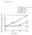
- Table 16 and FIG. 5 respectively show variations in degree of vacuum measured against the elapse of days when the vacuum thermal insulating material is arranged in a nitrogen atmosphere.
- Active carbons having pores 5%, 10%, and 20% greater than the diameter of nitrogen molecules were respectively used as the adsorbent in A, B, and C of Embodiment 5 in Table 16.
- an active carbon having 3%-greater pores, which are smaller than 5%-greater pores (Comparison a) and active carbons having 25%-greater and 40%-greater pores, which are larger than 20%-greater pores (Comparison b) and (Comparison c) were respectively used as the adsorbent.
- the vacuum thermal insulating material did not include any adsorbent.
- Embodiment 5 substantially no variation in degree of vacuum was observed in Embodiment 5 even after 90 days, whereas the degree of vacuum worsened in any adsorbents of Comparisons.
- the physisorption using, for example, active carbon is applied to adsorb the gas molecules, importance is placed on the relationship between the diameter of the gas molecules to be adsorbed and the diameter of pores of the adsorbent.
- the diameter of pores is only 5% to 20% greater than the diameter of the gas molecules to be adsorbed. This significantly lowers the kinetic energy of the gas molecules taken into the pores by the capillarity and makes the adsorption energy predominant.
- the physisorption is thus applicable to the vacuum thermal insulating material.
- the vacuum thermal insulating material 1 of Embodiment 5 utilizing the process of physisorption maintains the performance of thermal insulation without worsening the degree of vacuum over a long time period.
- Factors attaining heat conduction in the powdery vacuum thermal insulating material include solid heat conduction due to the contact of particles in the powder, gas heat conduction due to the collision of gas molecules in the pores of the powder, and radiation heat conduction. For the improvement in performance of thermal insulation, it is required to reduce the respective factors of heat conduction.
- the powdery vacuum thermal insulating material 1 has very small voids formed by the powder. This results in little effects of gas heat conduction due to the collision of gas molecules.
- the effect of solid heat conduction due to the contact of particles in the powder can be reduced by controlling the shape of the organic powder.
- the effect of heat conduction by radiation should also be decreased to improve the performance of thermal insulation.
- the property regarding absorption of the vibrational energy is characteristic of the material and expressed as the reflectance.
- the high reflectance enables reflection of the vibrational energy and thereby reduces the effect of heat conduction by radiation. It is accordingly important to optimize the reflectance.
- the reflectance is limited to be equal to or greater than 0.9.
- the vacuum thermal insulating material 1 of Embodiment 5 accordingly had little heat conduction by radiation and improved performance of thermal insulation.
- Table 17 shows the performance of thermal insulation in Embodiment 5 when aluminum powder having the hot wire reflectance of not less than 0.9 was added to reduce the heat conduction by radiation and improve the performance of thermal insulation. Comparison shows the performance of thermal insulation when a metal powder having the reflectance of less than 0.9 was added. For the measurement under the identical conditions, the amount of addition was fixed to 5 % by weight and the degree of vacuum was regulated to 0.1 mmHg. The performance of thermal insulation was expressed as the thermal conductivity measured at the average temperature of 24°C with a device for measuring thermal conductivity AUTO-A manufactured by Eiko Seiki Co., Ltd. specified aforementioned.
- urethane foam waste as the organic powder decreases the materials cost and thus remarkably reduces the whole manufacturing cost.
- the urethane foam waste can not be pulverized by grinding. This increases the size of the voids formed by the aggregate of organic powder and enhances the gas heat conduction due to the collision of gas molecules.
- One method applicable to solve the above problem adds an inorganic powder for surface modification of the organic powder, which improves the fluidity of the powder and decreases the size of the voids formed by the aggregate.
- Addition of an inorganic powder implements surface modification because of the mechanochemical reaction that occurs when the process of mixing an organic powder with an inorganic powder and stirring the mixture gives the kinetic energy. This effect is varied with the activity of the inorganic powder added.
- the restriction of the inorganic powder is accordingly important to realize the cost reduction.
- wet silica powder is used as the inorganic powder in Embodiment 5. Because of the characteristics of the manufacturing process, the wet silica powder has a greater number of silanol groups on its surface than the dry silica powder. Addition of even a very small amount of the wet silica powder having a strong polarity enables surface modification, thereby reducing the size of pores formed by the aggregate. Even when the urethane foam waste is used as the organic powder, this decreases the effect of gas heat conduction due to the collision of gas molecules. This structure ensures the high performance of thermal insulation and enables utilization of the waste to attain the remarkable cost reduction.
- Table 18 shows the relationship between the amount of addition and the performance of thermal insulation when wet silica powder as the embodiment and dry silica powder as the comparison were respectively added to the inorganic powder used as a modifier.
- the amount of addition of silica powder was set in three levels, that is, 5, 10, and 15 % by weight, and the degree of vacuum was regulated to 0.1 mmHg.
- the thermal conductivity representing the performance of thermal insulation was measured at the average temperature of 24°C with a device for measuring thermal conductivity AUTO-A manufactured by Eiko Seiki Co., Ltd. specified aforementioned.
- the embodiment using the wet silica powder has the improved performance of thermal insulation. Because of the characteristics of the manufacturing process, the wet silica powder has a greater number of silanol groups on its surface than the dry silica powder. Addition of even a very small amount of the wet silica powder having a strong polarity enables surface modification. Even when the urethane foam waste is used as the organic powder, this decreases the effect of gas heat conduction due to the collision of gas molecules. Application of the wet silica powder to the embodiment ensures the high performance of thermal insulation and enables utilization of the waste to attain the remarkable cost reduction.
- the thermally insulating case 4 of the embodiment has a structure in which the vacuum thermal insulating material 1 of the embodiment using the wet silica powder is arranged on one surface of a thermal insulating foamed material 5 that is composed of hard urethane foam, and accommodated in a sealed space defined by an outer casing 6 and an inner casing 7.
- the vacuum thermal insulating material 1 is attached to the inner wall of either the inner casing 7 or the outer casing 6 in the sealed space.
- the dimensions of the vacuum thermal insulating material 1 are 1.0 m x 0.5 m x 0.02 m.
- the vacuum thermal insulating material 1 has excellent performance of thermal insulation and keeps the high reliability over a long time period.
- the thermally insulating case constructed as above accordingly maintains the high performance of thermal insulation over a long time period.
- the refrigerator using the thermally insulating case 4 does not lead to an excessive operating efficiency of the compressor with an abrupt change of the outside temperature, thereby solving the problems, such as deterioration of the quality of food kept in the refrigerator.
- the shape of the organic powder included in the core material 2 is restricted to the needle-like form.
- the bulking power of the organic powder effectively prevents the vacuum thermal insulating material 1 from having the closest packing arrangement, thereby reducing the weight of the vacuum thermal insulating material 1.
- the inorganic powder having pores 5% to 20% greater than the diameter of the adsorbed molecules is used as the adsorbent. This lessens the kinetic energy of the gas molecules taken into the pores by the capillarity and makes the adsorption energy predominant. The physisorption is then applicable to the vacuum thermal insulating material 1 of Embodiment 5, which can thus be used over a long time period.
- the powdery material having the reflectance of 0.9 or more is added to the vacuum thermal insulating material 1 of Embodiment 5. This prevents the vibrational energy due to the radiation from being absorbed.
- the vacuum thermal insulating material 1 of Embodiment 5 can thus reduce the heat conduction by radiation and has the improved performance of thermal insulation.
- the inorganic powder used as the surface modifier is restricted to the wet silica powder. Even when the urethane foam waste is used as the organic powder, this decreases the effect of gas heat conduction due to the collision of gas molecules and ensures the high performance of the vacuum thermal insulating material 1 of Embodiment 5.
- the vacuum thermal insulating material 1 of Embodiment 5 enables utilization of the waste to attain the remarkable cost reduction.
- the vacuum thermal insulating material 1 keeps the high reliability over a long time period and has excellent performance of thermal insulation.
- the thermally insulating case 4 constructed by laying the vacuum thermal insulating material 1 and the thermal insulating foamed material 5 one upon the other maintains the high performance of thermal insulation over a long time period.
- the refrigerator or freezer using the thermally insulating case 4 of Embodiment 5 does not cause the compressor to be excessively operated with an abrupt change of the outside temperature, thereby solving the problems, such as deterioration of the quality of food kept in the refrigerator.
- the following describes a vacuum thermal insulating material 1 and a thermally insulating case 4 using the vacuum thermal insulating material 1 as Embodiment 6 of the present invention.
- the structures of the vacuum thermal insulating material 1 and the thermally insulating case 4 of Embodiment 6 are identical with those of Embodiment 1 shown in and described with FIGs. 1 and 2 and are thus not described here specifically.
- the vacuum thermal insulating material 1 is obtained by packing a core material 2 composed of ground powder of urethane foam and synthetic silica powder into a non-woven fabric having gas permeability, arranging the packed core material 2 in an outer member 3 composed of a metal-plastic film laminate, and sealing the outer member 3 under reduced pressure.
- Volume Ration of Gas Phase [%] Thermal Conductivity [kcal/mh°C] 85 0.0045 75 0.0045 65 0.0045 60 0.0050 55 0.0065 50 0.0075
- Table 19 shows the relationship between the volume ratio of gas phase in the core material 2 and the thermal conductivity representing the performance of thermal insulation.
- the bulk density represents the density of a certain quantity of powder including voids under the condition that a number of particles are accumulated in the presence of voids.
- the true density represents the actual density of the solid portion of the powdery material excluding the voids and is given as the mass per unit volume.
- Table 19 shows that the performance of thermal insulation is lowered with a decrease in volume ratio of gas phase.
- the performance of thermal insulation is remarkably lowered when the volume ratio of gas phase becomes less than 60%.
- volume ratio of gas phase increases the contact of particles and thereby enhances the solid heat conduction.
- volume ratio of gas phase becomes smaller than 60%, the particles approach to one another more closely. This makes the aggregation energy larger than the kinetic energy of the powder, and thereby leading to the closest packing arrangement.
- the closest packing arrangement remarkably increases the solid heat conduction and significantly worsens the performance of thermal insulation.
- the volume ratio of gas phase is restricted to be equal to or greater than 60%. This structure effectively prevents the closest packing arrangement of the powder and improves the performance of thermal insulation.
- Table 20 shows variations in thermal conductivity representing the performance of thermal insulation with the elapse of time for various mean particle diameters of ground urethane foam.
- Urethane foam is ground to particles of appropriate mean diameter, which can then be used as an organic powder. Urethane foam has closed cells, so that the inappropriate diameter of ground particles causes a gas such as CFC to be present in the closed cells. The time-based diffusion of the gas from the closed cells in such urethane foam powder worsens the degree of vacuum and lowers the performance of thermal insulation.
- the mean particle diameter is restricted to be equal to or smaller than 150 ⁇ m. This effectively prevents the closed cells from remaining when ground powder of urethane foam is used as the organic powder.
- the structure of the vacuum thermal insulating material 1 of Embodiment 6 prevents the degree of vacuum from worsening due to the time-based diffusion of the gas from the closed cells, thereby solving the problem of a lowering of the performance of thermal insulation.
- Table 21 shows variations in thermal conductivity representing the performance of thermal insulation when the bulk density of the organic powder and the amount of addition of the inorganic powder are varied.
- addition of the inorganic powder improves the performance of thermal insulation when the bulk density is equal to or smaller than 150 kg/m 3 .
- Addition of the inorganic powder lowers the performance of thermal insulation when the bulk density exceeds 150 kg/m 3 .
- Addition of the inorganic powder improves the performance of thermal insulation when the bulk density is equal to or smaller than 150 kg/m 3 because of the following reasons.
- Addition of the inorganic powder improves the fluidity of the powder and thereby attains the close packing arrangement of the powder.
- the voids greater than the mean free path of the air accordingly disappear, and the gas heat conduction due to the collision of gas molecules is reduced. This enables the vacuum thermal insulating material including the inorganic powder added to the organic powder to have the improved performance of thermal insulation.
- the bulk density is selected as an index representing the packing rate of the organic powder, and the bulk density of the organic powder is restricted to be equal to or smaller than 150 kg/m 3 . This realizes the appropriate packing rate of the organic powder and enables the performance of thermal insulation to be improved by addition of the inorganic powder.
- Table 22 shows the relationship between the thermal conductivity representing the performance of thermal insulation and the mean pore diameter of the powdery mixture, which is obtained by adding the inorganic powder to the organic powder, at various degrees of vacuum.
- the mean pore diameter is calculated from the volume of the pores in the whole powder and the specific surface area and shows the mean value of the pores in the powder.
- the mean pore diameter is restricted to be equal to or smaller than 100 ⁇ m. This mostly eliminates the pores greater than the mean free path of the air in the vacuum thermal insulating material 1 of Embodiment 6 and lowers the pressure dependence.
- the thermally insulating case 4 of Embodiment 6 includes the vacuum thermal insulating material 1 discussed above, a thermal insulating foamed material 5 composed of hard urethane foam, an outer casing 6, and an inner casing 7.
- the vacuum thermal insulating material 1 of the thermally insulating case 4 is attached to the inner wall of either the inner casing 7 or the outer casing 6.
- the dimensions of the vacuum thermal insulating material 1 are 1.0 m x 0.5 m x 0.02 m.
- the vacuum thermal insulating material 1 of Embodiment 6 has excellent performance of thermal insulation and very low pressure dependence.
- the thermally insulating case 4 constructed as above thus keeps the high performance of thermal insulation over a long time period.
- the refrigerator or freezer using the thermally insulating case 4 does not cause the compressor to be excessively operated with an abrupt change of the outside temperature, thereby solving the problems, such as deterioration of the quality of food kept in the refrigerator.
- the volume ratio of gas phase in the core material 2 is restricted to be equal to or higher than 60%, which leads to less contact of the particles.
- the vacuum thermal insulating material 1 of Embodiment 6 has little solid heat conduction via the contact of the particles and possesses the high performance of thermal insulation.
- the mean particle diameter of the organic powder is restricted to be equal to or smaller than 150 ⁇ m, so that the ground powder of foamed urethane foam including the closed cells is applicable.
- This structure solves the problems of worsened degree of vacuum, which is caused by diffusion of a gas from the closed cells remaining in the foamed urethane foam, and the resulting drop in performance of thermal insulation.
- the urethane foam waste can thus be applicable to the vacuum thermal insulating material 1 of Embodiment 6, which leads to the remarkable cost reduction.
- the bulk density of the organic powder is restricted to be equal to or lower than 150 kg/m3. This structure enables the inorganic power added to the organic powder to improve the performance of thermal insulation without causing the excess contact of the particles.
- the mean pore diameter is restricted to be equal to or smaller than 100 ⁇ m in the powdery mixture obtained by mixing the organic powder with the inorganic powder. This structure lessens the collision of gas molecules in the pores at a low degree of vacuum of 0.1 mmHg that can be readily realized at a low cost in the industrial level.
- the vacuum thermal insulating material 1 of Embodiment 6 accordingly has excellent performance of thermal insulation and low pressure dependence.
- the thermally insulating case 4 of Embodiment 6 includes the thermal insulating foamed material and the vacuum thermal insulating material 1 arranged in a space defined by the case.
- the thermally insulating case 4 of Embodiment 6 accordingly maintains the excellent performance of thermal insulation over a long time period.
- the vacuum thermal insulating material of the present invention and the thermally insulating case using the vacuum thermal insulating material are applicable as heat insulation in refrigerators, freezers, and the like.
- the refrigerators and freezers to which the present invention is applied have excellent performance of thermal insulation, are light in weight and manufactured at a low cost, and maintain the high performance of thermal insulation over a long time period.
Landscapes
- Engineering & Computer Science (AREA)
- General Engineering & Computer Science (AREA)
- Mechanical Engineering (AREA)
- Thermal Insulation (AREA)
- Refrigerator Housings (AREA)
Claims (26)
- Vakuumwärmeisolierungsmaterial, umfassend ein Kernmaterial und ein Adsorbens, die in einem äußeren Element verpackt sind, wobei das Kernmaterial ein Pulver aus organischem Material, das ein Urethanmaterial ist, umfasst, das eine spezifische Oberfläche von nicht mehr als 20 m2/g aufweist, sowie ein Pulver aus anorganischem Material, das eine spezifische Oberfläche von mehr als 20 m2/g aufweist, ausgewählt aus einer Gruppe bestehend aus Silica, Perlit, Kieselgur, Aluminiumoxid und Titanoxid.
- Vakuumwärmeisolierungsmaterial nach Anspruch 1, wobei das Pulver aus organischem Material in dem Kernmaterial zermahlenes Pulver aus Schaumkunststoff umfasst.
- Vakuumwärmeisolierungsmaterial nach Anspruch 1, wobei eine Füllung des Pulvers aus anorganischem Material in dem Kernmaterial nicht weniger als 2 Gew.-% und nicht mehr als 50 Gew.-% beträgt.
- Vakuumwärmeisolierungsmaterial nach Anspruch 1, wobei das Vakuumwärmeisolierungsmaterial ein Pulver aus anorganischem Material mit einer nadelartigen Kristallform als einen Oberflächenmodifizierer für das Pulver aus organischem Material umfasst.
- Vakuumwärmeisolierungsmaterial nach Anspruch 4, wobei das anorganische Material, das als der Oberflächenmodifizierer funktioniert, ein Pulver aus Calciumsilicat umfasst.
- Vakuumwärmeisolierungsmaterial nach Anspruch 5, wobei das Molverhältnis von SiO2 / CaO in dem Pulver aus Calciumsilicat nicht weniger als 2, jedoch nicht größer als 3 ist.
- Vakuumwärmeisolierungsmaterial nach Anspruch 5, wobei das Pulver aus Calciumsilicat so behandelt ist, dass es hydrophob ist.
- Vakuumwärmeisolierungsmaterial nach Anspruch 4, wobei das Pulver aus organischem Material so behandelt ist, dass es hydrophob ist.
- Vakuumwärmeisolierungsmaterial nach Anspruch 4, wobei das Pulver aus organischem Material mit einem Faserwerkstoff vermischt ist.
- Vakuumwärmeisolierungsmaterial nach Anspruch 1, wobei das Vakuumwärmeisolierungsmaterial ein Pulver umfasst, das wenigstens ein Salz einer Fettsäure als einen Oberflächenmodifizierer für das Pulver aus organischem Material enthält.
- Vakuumwärmeisolierungsmaterial nach Anspruch 10, wobei das Salz der Fettsäure, das als der Oberflächenmodifizierer funktioniert, wenigstens Calciumstearat-Pulver umfasst.
- Vakuumwärmeisolierungsmaterial nach Anspruch 10, wobei der Oberflächenmodifizierer Silica-Pulver oder Calciumsilicat-Pulver und Calciumstearat-Pulver umfasst.
- Vakuumwärmeisolierungsmaterial nach Anspruch 10, wobei das Pulver aus organischem Material ein Schaumkunststoff-Pulver umfasst, das durch Mahlen erhalten wird.
- Vakuumwärmeisolierungsmaterial nach Anspruch 1, wobei das Pulver aus organischem Material eine nadelartige Kristallform aufweist.
- Vakuumwärmeisolierungsmaterial nach Anspruch 1, wobei das Adsorbens ein Pulver aus anorganischem Material umfasst, das Poren aufweist, die 5 % bis 20 % größer sind als der Moleküldurchmesser eines adsorbierten Materials.
- Vakuumwärmeisolierungsmaterial nach Anspruch 1, wobei das Kernmaterial ein Pulver mit einem Reflexionsgrad von 0,9 oder größer umfasst.
- Vakuumwärmeisolierungsmaterial nach Anspruch 1, wobei das Pulver aus anorganischem Material ein benetztes Silica-Pulver umfasst.
- Vakuumwärmeisolierungsmaterial nach Anspruch 1, wobei das Kernmaterial ein Gasphasen-Volumenverhältnis von 60 % oder mehr aufweist.
- Vakuumwärmeisolierungsmaterial nach Anspruch 1, wobei das Pulver aus organischem Material einen mittleren Teilchendurchmesser aufweist, der im Wesentlichen gleich oder kleiner als 150 µm ist.
- Vakuumwärmeisolierungsmaterial nach Anspruch 1, wobei das Pulver aus organischem Material eine Schüttdichte aufweist, die im Wesentlichen gleich oder kleiner als 150 kg/m3 ist.
- Vakuumwärmeisolierungsmaterial nach Anspruch 1, wobei ein mittlerer Porendurchmesser des Kernmaterials, welches das Pulver aus organischem Material und das Pulver aus anorganischem Material umfasst, im Wesentlichen gleich oder kleiner als 100 µm ist.
- Wärmeisolierender Kasten, umfassend:ein äußeres Gehäuse;ein inneres Gehäuse;ein wärmeisolierender Schaumstoff, der in einen Raum gepackt ist, der durch das äußere Gehäuse und das innere Gehäuse definiert ist; undein Vakuumwärmeisolierungsmaterial nach Anspruch 1, das an einer Innenwand des äußeren Gehäuses oder des inneren Gehäuses angebracht ist und ein Kernmaterial aufweist, das ein Pulver aus organischem Material umfasst, das eine spezifische Oberfläche von nicht mehr als 20 m2/g aufweist, sowie ein Pulver aus anorganischem Material, das eine spezifische Oberfläche von mehr als 20 m2/g aufweist, und ein Adsorbens.
- Wärmeisolierender Kasten nach Anspruch 22, wobei der wärmeisolierende Kasten ein Pulver aus anorganischem Material mit einer nadelartigen Kristallform als einen Oberflächenmodifizierer für das Pulver aus organischem Material umfasst.
- Wärmeisolierender Kasten nach Anspruch 22, wobei der wärmeisolierende Kasten ein Pulver umfasst, das wenigstens ein Salz einer Fettsäure als einen Oberflächenmodifizierer für das Pulver aus organischem Material enthält.
- Wärmeisolierender Kasten nach Anspruch 22, wobei das Pulver aus organischem Material eine nadelartige Kristallform aufweist.
- Wärmeisolierender Kasten nach Anspruch 22, wobei das Kernmaterial ein Gasphasen-Volumenverhältnis von 60 % oder mehr aufweist.
Applications Claiming Priority (19)
| Application Number | Priority Date | Filing Date | Title |
|---|---|---|---|
| JP4702495 | 1995-03-07 | ||
| JP47024/95 | 1995-03-07 | ||
| JP4702495 | 1995-03-07 | ||
| JP7874395 | 1995-04-04 | ||
| JP7874395 | 1995-04-04 | ||
| JP78743/95 | 1995-04-04 | ||
| JP252723/95 | 1995-09-29 | ||
| JP25272495 | 1995-09-29 | ||
| JP25272395 | 1995-09-29 | ||
| JP25272395 | 1995-09-29 | ||
| JP252724/95 | 1995-09-29 | ||
| JP25272495 | 1995-09-29 | ||
| JP54096 | 1996-01-08 | ||
| JP54096 | 1996-01-08 | ||
| JP54196 | 1996-01-08 | ||
| JP54196 | 1996-01-08 | ||
| JP540/96 | 1996-01-08 | ||
| JP541/96 | 1996-01-08 | ||
| PCT/JP1996/000533 WO1996027754A1 (en) | 1995-03-07 | 1996-03-06 | Vacuum heat-insulator and heat-insulating box using the insulator |
Publications (3)
| Publication Number | Publication Date |
|---|---|
| EP0762043A1 EP0762043A1 (de) | 1997-03-12 |
| EP0762043A4 EP0762043A4 (de) | 1998-07-15 |
| EP0762043B1 true EP0762043B1 (de) | 2003-08-27 |
Family
ID=27547535
Family Applications (1)
| Application Number | Title | Priority Date | Filing Date |
|---|---|---|---|
| EP96905003A Expired - Lifetime EP0762043B1 (de) | 1995-03-07 | 1996-03-06 | Vakuumwärmeisolierung und wärmeisolierender behälter unter verwendung dieser isolierung |
Country Status (8)
| Country | Link |
|---|---|
| EP (1) | EP0762043B1 (de) |
| JP (1) | JP3752519B2 (de) |
| KR (1) | KR100223546B1 (de) |
| CN (1) | CN1071012C (de) |
| AU (1) | AU692115B2 (de) |
| CA (1) | CA2189894A1 (de) |
| DE (1) | DE69629636T2 (de) |
| WO (1) | WO1996027754A1 (de) |
Families Citing this family (18)
| Publication number | Priority date | Publication date | Assignee | Title |
|---|---|---|---|---|
| US5877100A (en) * | 1996-09-27 | 1999-03-02 | Cabot Corporation | Compositions and insulation bodies having low thermal conductivity |
| JP3792801B2 (ja) * | 1996-10-07 | 2006-07-05 | 松下冷機株式会社 | 真空断熱体 |
| DE19758219A1 (de) * | 1997-12-31 | 1999-07-01 | Uvt Umwelt Und Verfahrens Tech | Vakuumisolationspaneel |
| DE19928011A1 (de) * | 1999-06-19 | 2000-12-21 | Porextherm Daemmstoffe Gmbh | Isolierplatte, insbesondere für den Niedertemperaturbereich |
| DE102004031967B4 (de) * | 2004-07-01 | 2015-01-15 | Porextherm Dämmstoffe GmbH | Verfahren zur Herstellung eines Vakuumisolationsformkörpers |
| US20060272727A1 (en) * | 2005-06-06 | 2006-12-07 | Dinon John L | Insulated pipe and method for preparing same |
| DE102005045726A1 (de) * | 2005-09-23 | 2007-04-05 | Va-Q-Tec Ag | Verfahren zur Herstellung eines folienumhüllten Vakuumdämmkörpers |
| JP4752422B2 (ja) * | 2005-09-26 | 2011-08-17 | パナソニック株式会社 | 真空断熱体の製造方法 |
| KR100940975B1 (ko) * | 2005-09-26 | 2010-02-05 | 파나소닉 주식회사 | 기체 흡착 디바이스, 기체 흡착 디바이스를 이용한 진공단열체 및 진공 단열체의 제조 방법 |
| JP5443400B2 (ja) * | 2011-01-12 | 2014-03-19 | 三菱電機株式会社 | 真空断熱材、断熱箱、および真空断熱材の製造方法 |
| KR101657989B1 (ko) * | 2012-07-12 | 2016-09-21 | 주식회사 케이씨씨 | 어닐링 처리된 무바인더 유리섬유를 포함하는 진공 단열재 |
| CN102788229B (zh) * | 2012-07-23 | 2015-05-13 | 青岛科瑞新型环保材料有限公司 | 一种密度均匀、高生产效率的真空绝热板的制作方法 |
| KR101365657B1 (ko) | 2012-08-07 | 2014-02-24 | 주식회사 경동원 | 팽창 퍼라이트를 이용한 저밀도 무기질 파우더 단열재, 이의 제조 방법 및 이의 성형기 |
| WO2016143781A1 (ja) * | 2015-03-10 | 2016-09-15 | 株式会社 東芝 | 真空断熱パネル、コア材、冷蔵庫 |
| JP6742076B2 (ja) * | 2015-05-07 | 2020-08-19 | 日立グローバルライフソリューションズ株式会社 | 真空断熱材および真空断熱材の製造方法 |
| CN105240652A (zh) * | 2015-09-06 | 2016-01-13 | 靳亲国 | 一种真空结构高温隔热板及其制备方法 |
| CN107323696A (zh) * | 2017-07-24 | 2017-11-07 | 苏州宏久航空防热材料科技有限公司 | 一种具有陶瓷外壳的高温真空绝热复合材料 |
| CN115321589B (zh) * | 2022-09-16 | 2023-09-12 | 东北大学 | 氟钛酸盐铝热还原制备钛或钛合金过程中副产物的综合利用方法 |
Family Cites Families (10)
| Publication number | Priority date | Publication date | Assignee | Title |
|---|---|---|---|---|
| JPS58199953A (ja) * | 1982-05-17 | 1983-11-21 | 松下電器産業株式会社 | 断熱材 |
| JPH0670395B2 (ja) * | 1984-06-28 | 1994-09-07 | 三菱重工業株式会社 | デイ−ゼルエンジン用電子ガバナ |
| JPS6136595A (ja) * | 1984-07-30 | 1986-02-21 | 松下電器産業株式会社 | 真空断熱材 |
| DE3429151A1 (de) * | 1984-08-08 | 1986-02-20 | Brown, Boveri & Cie Ag, 6800 Mannheim | Isoliereinrichtung |
| JPS61103089A (ja) * | 1984-10-23 | 1986-05-21 | シャープ株式会社 | 真空断熱構造体 |
| JPS61144491A (ja) * | 1984-12-14 | 1986-07-02 | シャープ株式会社 | 真空断熱構造体 |
| JPS61144492A (ja) * | 1985-12-13 | 1986-07-02 | 松下電器産業株式会社 | 粉末真空断熱板 |
| JPH025958A (ja) * | 1988-06-27 | 1990-01-10 | Tokyo Rika:Kk | 賦香方法 |
| JPH0544889A (ja) * | 1991-08-13 | 1993-02-23 | Kubota Corp | 真空断熱体 |
| JPH05209700A (ja) * | 1992-01-31 | 1993-08-20 | Matsushita Refrig Co Ltd | 真空断熱材パック |
-
1996
- 1996-03-06 EP EP96905003A patent/EP0762043B1/de not_active Expired - Lifetime
- 1996-03-06 CN CN96190171A patent/CN1071012C/zh not_active Expired - Fee Related
- 1996-03-06 JP JP52676496A patent/JP3752519B2/ja not_active Expired - Lifetime
- 1996-03-06 AU AU65408/96A patent/AU692115B2/en not_active Ceased
- 1996-03-06 KR KR1019960706301A patent/KR100223546B1/ko not_active Expired - Fee Related
- 1996-03-06 DE DE69629636T patent/DE69629636T2/de not_active Expired - Fee Related
- 1996-03-06 CA CA 2189894 patent/CA2189894A1/en not_active Abandoned
- 1996-03-06 WO PCT/JP1996/000533 patent/WO1996027754A1/ja not_active Ceased
Also Published As
| Publication number | Publication date |
|---|---|
| DE69629636D1 (de) | 2003-10-02 |
| DE69629636T2 (de) | 2004-06-17 |
| WO1996027754A1 (en) | 1996-09-12 |
| AU6540896A (en) | 1996-09-23 |
| CN1071012C (zh) | 2001-09-12 |
| EP0762043A1 (de) | 1997-03-12 |
| CN1148427A (zh) | 1997-04-23 |
| EP0762043A4 (de) | 1998-07-15 |
| AU692115B2 (en) | 1998-05-28 |
| JP3752519B2 (ja) | 2006-03-08 |
| KR100223546B1 (ko) | 1999-10-15 |
| CA2189894A1 (en) | 1996-09-12 |
Similar Documents
| Publication | Publication Date | Title |
|---|---|---|
| EP0762043B1 (de) | Vakuumwärmeisolierung und wärmeisolierender behälter unter verwendung dieser isolierung | |
| JPWO1996027754A1 (ja) | 真空断熱体およびその真空断熱体を用いた断熱箱体 | |
| US6001450A (en) | Vacuum thermal insulating material and thermally insulating case using the same | |
| EP1510747B1 (de) | Vakuumwärmeisoliermaterial, verfahren zur herstellung desselben und kühlvorrichtung, die selbiges enthält | |
| US6859364B2 (en) | Portable information appliance | |
| EP1275894B1 (de) | Wärmeisolationsbehälter und ein für diesen benutztes material | |
| JP5669617B2 (ja) | エアロゲル及び該エアロゲルを用いた断熱材 | |
| JP2005036975A (ja) | 断熱材と、その製造方法、及びその断熱材を使用した機器 | |
| JP3482399B2 (ja) | 真空断熱材、および、真空断熱材の製造方法、ノート型コンピュータ、冷凍機器、電気湯沸かし器、オーブンレンジ | |
| JP2008215492A (ja) | 真空断熱材 | |
| JP2003074786A (ja) | 真空断熱材および真空断熱材の製造方法、ならびに真空断熱材を用いた冷蔵庫および冷凍機器,ノート型コンピュータ,電気湯沸かし器 | |
| JP2008215538A (ja) | 真空断熱材 | |
| JP3527727B2 (ja) | 真空断熱材及びその真空断熱材を用いた機器 | |
| JP4017713B2 (ja) | 真空断熱体、冷蔵庫、断熱パネル、及び真空断熱体の製造方法 | |
| JP2004011908A (ja) | 真空断熱材、および真空断熱材を用いた冷蔵庫 | |
| JP3558980B2 (ja) | 真空断熱材、および、真空断熱材の製造方法、冷凍冷蔵庫および冷凍機器、ノート型コンピュータ、電気湯沸かし器、オーブンレンジ | |
| JPH11106539A (ja) | 真空断熱材用ゲッタおよびその製造法 | |
| JP2004011756A (ja) | 真空断熱材、および真空断熱材を用いた冷蔵庫 | |
| JP2000291880A (ja) | 真空断熱材および真空断熱材の製造方法 | |
| JP3942700B2 (ja) | 発泡断熱材の製造方法 | |
| JPH09303945A (ja) | 真空断熱体および断熱箱体 | |
| JP2006105286A (ja) | 断熱体、冷凍機器及び冷温機器 | |
| JPH01157473A (ja) | 微細多孔体 | |
| JPH11300201A (ja) | 炭酸ガス吸着剤及び発泡断熱材及び断熱箱体 | |
| JPH11130888A (ja) | 真空断熱体、断熱箱体、断熱パネル、及び真空断熱体の製造方法 |
Legal Events
| Date | Code | Title | Description |
|---|---|---|---|
| PUAI | Public reference made under article 153(3) epc to a published international application that has entered the european phase |
Free format text: ORIGINAL CODE: 0009012 |
|
| 17P | Request for examination filed |
Effective date: 19961028 |
|
| AK | Designated contracting states |
Kind code of ref document: A1 Designated state(s): DE FR GB IT SE |
|
| A4 | Supplementary search report drawn up and despatched |
Effective date: 19980526 |
|
| AK | Designated contracting states |
Kind code of ref document: A4 Designated state(s): DE FR GB IT SE |
|
| 17Q | First examination report despatched |
Effective date: 20010213 |
|
| GRAH | Despatch of communication of intention to grant a patent |
Free format text: ORIGINAL CODE: EPIDOS IGRA |
|
| GRAS | Grant fee paid |
Free format text: ORIGINAL CODE: EPIDOSNIGR3 |
|
| GRAA | (expected) grant |
Free format text: ORIGINAL CODE: 0009210 |
|
| AK | Designated contracting states |
Designated state(s): DE FR GB IT SE |
|
| REG | Reference to a national code |
Ref country code: GB Ref legal event code: FG4D |
|
| REF | Corresponds to: |
Ref document number: 69629636 Country of ref document: DE Date of ref document: 20031002 Kind code of ref document: P |
|
| REG | Reference to a national code |
Ref country code: SE Ref legal event code: TRGR |
|
| ET | Fr: translation filed | ||
| PLBE | No opposition filed within time limit |
Free format text: ORIGINAL CODE: 0009261 |
|
| STAA | Information on the status of an ep patent application or granted ep patent |
Free format text: STATUS: NO OPPOSITION FILED WITHIN TIME LIMIT |
|
| 26N | No opposition filed |
Effective date: 20040528 |
|
| REG | Reference to a national code |
Ref country code: FR Ref legal event code: CA |
|
| PGFP | Annual fee paid to national office [announced via postgrant information from national office to epo] |
Ref country code: GB Payment date: 20060301 Year of fee payment: 11 |
|
| PGFP | Annual fee paid to national office [announced via postgrant information from national office to epo] |
Ref country code: DE Payment date: 20060302 Year of fee payment: 11 |
|
| PGFP | Annual fee paid to national office [announced via postgrant information from national office to epo] |
Ref country code: FR Payment date: 20060308 Year of fee payment: 11 |
|
| PGFP | Annual fee paid to national office [announced via postgrant information from national office to epo] |
Ref country code: IT Payment date: 20060331 Year of fee payment: 11 |
|
| PG25 | Lapsed in a contracting state [announced via postgrant information from national office to epo] |
Ref country code: SE Free format text: LAPSE BECAUSE OF NON-PAYMENT OF DUE FEES Effective date: 20070307 |
|
| EUG | Se: european patent has lapsed | ||
| GBPC | Gb: european patent ceased through non-payment of renewal fee |
Effective date: 20070306 |
|
| REG | Reference to a national code |
Ref country code: FR Ref legal event code: ST Effective date: 20071130 |
|
| PG25 | Lapsed in a contracting state [announced via postgrant information from national office to epo] |
Ref country code: DE Free format text: LAPSE BECAUSE OF NON-PAYMENT OF DUE FEES Effective date: 20071002 |
|
| PGFP | Annual fee paid to national office [announced via postgrant information from national office to epo] |
Ref country code: SE Payment date: 20060306 Year of fee payment: 11 |
|
| PG25 | Lapsed in a contracting state [announced via postgrant information from national office to epo] |
Ref country code: GB Free format text: LAPSE BECAUSE OF NON-PAYMENT OF DUE FEES Effective date: 20070306 |
|
| PG25 | Lapsed in a contracting state [announced via postgrant information from national office to epo] |
Ref country code: FR Free format text: LAPSE BECAUSE OF NON-PAYMENT OF DUE FEES Effective date: 20070402 |
|
| PG25 | Lapsed in a contracting state [announced via postgrant information from national office to epo] |
Ref country code: IT Free format text: LAPSE BECAUSE OF NON-PAYMENT OF DUE FEES Effective date: 20070306 |