EP0753748A2 - Probenfördereinrichtung - Google Patents
Probenfördereinrichtung Download PDFInfo
- Publication number
- EP0753748A2 EP0753748A2 EP96305159A EP96305159A EP0753748A2 EP 0753748 A2 EP0753748 A2 EP 0753748A2 EP 96305159 A EP96305159 A EP 96305159A EP 96305159 A EP96305159 A EP 96305159A EP 0753748 A2 EP0753748 A2 EP 0753748A2
- Authority
- EP
- European Patent Office
- Prior art keywords
- tray
- sample
- sample rack
- rack
- magnet
- Prior art date
- Legal status (The legal status is an assumption and is not a legal conclusion. Google has not performed a legal analysis and makes no representation as to the accuracy of the status listed.)
- Granted
Links
Images


Classifications
-
- B—PERFORMING OPERATIONS; TRANSPORTING
- B01—PHYSICAL OR CHEMICAL PROCESSES OR APPARATUS IN GENERAL
- B01L—CHEMICAL OR PHYSICAL LABORATORY APPARATUS FOR GENERAL USE
- B01L9/00—Supporting devices; Holding devices
- B01L9/06—Test-tube stands; Test-tube holders
-
- G—PHYSICS
- G01—MEASURING; TESTING
- G01N—INVESTIGATING OR ANALYSING MATERIALS BY DETERMINING THEIR CHEMICAL OR PHYSICAL PROPERTIES
- G01N35/00—Automatic analysis not limited to methods or materials provided for in any single one of groups G01N1/00 - G01N33/00; Handling materials therefor
- G01N35/02—Automatic analysis not limited to methods or materials provided for in any single one of groups G01N1/00 - G01N33/00; Handling materials therefor using a plurality of sample containers moved by a conveyor system past one or more treatment or analysis stations
- G01N35/04—Details of the conveyor system
-
- B—PERFORMING OPERATIONS; TRANSPORTING
- B01—PHYSICAL OR CHEMICAL PROCESSES OR APPARATUS IN GENERAL
- B01L—CHEMICAL OR PHYSICAL LABORATORY APPARATUS FOR GENERAL USE
- B01L2200/00—Solutions for specific problems relating to chemical or physical laboratory apparatus
- B01L2200/02—Adapting objects or devices to another
- B01L2200/025—Align devices or objects to ensure defined positions relative to each other
-
- G—PHYSICS
- G01—MEASURING; TESTING
- G01N—INVESTIGATING OR ANALYSING MATERIALS BY DETERMINING THEIR CHEMICAL OR PHYSICAL PROPERTIES
- G01N35/00—Automatic analysis not limited to methods or materials provided for in any single one of groups G01N1/00 - G01N33/00; Handling materials therefor
- G01N35/00584—Control arrangements for automatic analysers
- G01N35/00722—Communications; Identification
- G01N35/00732—Identification of carriers, materials or components in automatic analysers
- G01N2035/00742—Type of codes
- G01N2035/00752—Type of codes bar codes
-
- G—PHYSICS
- G01—MEASURING; TESTING
- G01N—INVESTIGATING OR ANALYSING MATERIALS BY DETERMINING THEIR CHEMICAL OR PHYSICAL PROPERTIES
- G01N35/00—Automatic analysis not limited to methods or materials provided for in any single one of groups G01N1/00 - G01N33/00; Handling materials therefor
- G01N35/02—Automatic analysis not limited to methods or materials provided for in any single one of groups G01N1/00 - G01N33/00; Handling materials therefor using a plurality of sample containers moved by a conveyor system past one or more treatment or analysis stations
- G01N35/04—Details of the conveyor system
- G01N2035/046—General conveyor features
- G01N2035/0467—Switching points ("aiguillages")
-
- G—PHYSICS
- G01—MEASURING; TESTING
- G01N—INVESTIGATING OR ANALYSING MATERIALS BY DETERMINING THEIR CHEMICAL OR PHYSICAL PROPERTIES
- G01N35/00—Automatic analysis not limited to methods or materials provided for in any single one of groups G01N1/00 - G01N33/00; Handling materials therefor
- G01N35/02—Automatic analysis not limited to methods or materials provided for in any single one of groups G01N1/00 - G01N33/00; Handling materials therefor using a plurality of sample containers moved by a conveyor system past one or more treatment or analysis stations
- G01N35/04—Details of the conveyor system
- G01N2035/0474—Details of actuating means for conveyors or pipettes
- G01N2035/0477—Magnetic
-
- G—PHYSICS
- G01—MEASURING; TESTING
- G01N—INVESTIGATING OR ANALYSING MATERIALS BY DETERMINING THEIR CHEMICAL OR PHYSICAL PROPERTIES
- G01N35/00—Automatic analysis not limited to methods or materials provided for in any single one of groups G01N1/00 - G01N33/00; Handling materials therefor
- G01N35/02—Automatic analysis not limited to methods or materials provided for in any single one of groups G01N1/00 - G01N33/00; Handling materials therefor using a plurality of sample containers moved by a conveyor system past one or more treatment or analysis stations
- G01N35/026—Automatic analysis not limited to methods or materials provided for in any single one of groups G01N1/00 - G01N33/00; Handling materials therefor using a plurality of sample containers moved by a conveyor system past one or more treatment or analysis stations having blocks or racks of reaction cells or cuvettes
Definitions
- This invention relates to a sample transport system; more particularly, it relates to moving test samples into and out of an analyzer instrument by a magnetic conveyor system.
- sample rack As is known in the art, there is a trend in hospitals, clinics, laboratories and other locations to perform tests (assays) on samples of patient specimens such as blood, spinal fluid, urine, serum, plasma, and the like using automated analyzer systems.
- the samples are typically placed in a container such as a sample cup, a primary tube, a cuvette or any other suitable container.
- a container such as a sample cup, a primary tube, a cuvette or any other suitable container.
- One or more of such containers may then be arranged in a so-called sample rack.
- the sample rack is placed in a load area or input queue of the analyzer instrument and then is moved to a position where at least a portion of the sample is collected for testing in the analyzer instrument. After the sample is collected for testing in the analyzer instrument, the sample rack is moved to an output or exit queue where the user can remove the sample rack from the analyzer instrument.
- a user can physically place sample racks holding one or more samples to be tested in the load area and after the samples are collected the user can remove the sample racks from the output queue.
- the entry and exit queues of the analyzer instrument are generally exposed to a user.
- mechanical pushers or conveyor mechanisms are used to move the sample racks along the input and output queues.
- a pusher apparatus is positioned above a tray on which the sample racks are disposed.
- a lead screw driven by a motor or a spring driven push block pushes the sample racks along a surface of the tray.
- the input and output queues are generally susceptible to sample fluid spills and thus it is important to allow the queues to be easily cleaned.
- the above mentioned safety precautions limit user accessibility to the tray.
- the pusher apparatus is preferably stopped to allow the user to clean the input and exit queues in the regions proximate the pusher mechanisms. This usually slows or stops operation of the system.
- any openings in the surface of the input and output trays upon which the sample racks are placed may expose interior portions of the transport system or analyzer instrument to fluid spills. Such interior areas are generally not easily accessible and if such areas become contaminated by fluid, further complications arise in the cleaning procedures.
- a transport system for moving a sample rack having a magnetically attractive region includes a drive system, a magnet coupled to the drive system and movable in response to the drive system and a tray having a first surface adapted to receive the sample rack wherein the first surface of the tray is disposed over and spaced a predetermined distance from a first surface of the magnet such that a magnetic force provided by the magnet is present at the first surface of the tray.
- a magnetic conveyor system is provided.
- the tray may be provided from a material which promotes cleaning thereby enabling the tray to be easily cleaned.
- the tray may be fabricated of aluminum having a Teflon surface coating.
- the tray can be coupled to a cover which completely encloses the drive system and further protects the drive system from sample spills and other contaminants.
- the tray surface upon which racks are disposed is stationary and thus does not cause excessive wear of the sample racks due to constant rubbing of a moving belt on the bottom surface of a stationary sample rack.
- there are no moving parts to which a user is exposed and thus the transport system minimizes the safety concerns of a user in highly accessible areas such as an input queue of an analyzer instrument.
- the tray is provided having a rectangular shape with a length selected to hold a predetermined number of sample racks.
- each sample rack holds one or more test tubes.
- the sample racks may be loaded onto any portion of the tray which serves as an input queue of the analyzer instrument.
- the drive system located beneath the first surface of the tray includes a first shaft disposed below a first end of the tray and a second shaft disposed below a second different end of the tray.
- the shafts are rotatably mounted in a base.
- Each shaft has a pair of pulleys disposed on opposite ends thereto.
- a urethane belt is disposed around opposing pulleys of the two shafts.
- a plurality of bar magnet assemblies extend between the urethane belts.
- the pulley sets synchronously drive the two urethane belts and thus the magnet assemblies.
- the magnet assemblies include a pair of magnets oriented such that opposite poles of each magnet face the same tray surface forming a magnet circuit which includes a magnetic field above the first surface of the tray.
- the magnet assemblies and the first surface of the tray are closely spaced such that the magnets freely move with the urethane belts below the surface of the tray.
- each sample rack is provided having two cavities on a bottom surface thereof.
- the cavities are symmetrically located about opposite sides of a center line of the sample rack.
- Disposed in each of the cavities is a magnetizable plate positioned at the bottom surface of the sample rack such that when the sample rack is disposed on the tray the plates are aligned with the magnets of the magnet assemblies which pass below the surface of the tray.
- the magnetic field generated by the magnet assemblies attract the plates disposed in the bottom surface of the sample rack and engages the plate with sufficient force such that the sample rack moves in concert with the magnet assembly as the belts move.
- At least a portion of a first surface of the plate may be disposed at an angle with respect to the surface of the magnet assembly such that the magnetic force provided by the magnet assemblies gradually builds as the belts move to lower the backward acceleration of the rack as the magnet assembly first approaches the sample rack. Consequently, the sample rack smoothly transitions from a stationary state to a moving state.
- the sample rack is also provided having a pair of rails projecting from the bottom surface thereof.
- the rails decrease the surface area of the sample rack which contact the tray and thus reduce frictional forces between the sample rack and the tray.
- the bottom surface of the sample rack is also provided with a recess region which accepts projecting guide from the first surface of the tray. The guide positions the sample rack along the tray.
- the sample rack also includes front and back edge guides which prevent the sample rack from tipping while it is on the tray and ensures that the rack is properly aligned on the tray.
- the front edge guide prevents the sample rack from tipping when the sample rack is placed in a load position of the tray.
- the sample rack has openings to accept sample-containing vessels such as test tubes. Disposed on each of the openings is a finger spring which is placed in compression when a sample-containing vessel is placed in the opening, thus securing the sample vessel in the sample rack.
- the spring is sized such that different size test tubes may be placed and properly secured in the sample rack.
- an automated analyzer instrument 10 used to perform diagnostic tests on test samples includes instrumentation generally denoted 12 and a transport system 14.
- the instrumentation 12 may typically include an incubation chamber and processing stations similar to the types described in EP-A-712000, a luminometer which may be similar to the type described in EP-A-616208 and a fluid moving system generally provide from pipettes controlled by robotic arms.
- the transport system 14 allows a continuous supply of samples for uninterrupted testing.
- the transportation system 14 includes an input queue 16, a process queue 18 and an output queue 20.
- the input queue 16 moves sample-containing vessels such as test tubes, for example, toward a load position 22 located at one end of the input queue 16.
- the test tubes hold samples of patient bodily fluid specimens and the like to be analyzed by the analyzer instrument 10. Once the test tubes reach the load position 22, an infeed apparatus 24 moves the sample-containing test tube from the input queue 16 to a predetermined position on the process queue 18.
- the test tubes move from the input queue 16 to the process queue 18, the test tubes pass by a bar code reader 26 disposed proximate the load position 22 of the input queue 16.
- the bar code reader 26 deciphers a bar code typically attached to each test tube and to each rack by a label and transmits its information to a system controller 28 which performs a variety of functions including tracking the samples provided to the process queue 12 and scheduling the order in which the samples are tested.
- the sample rack is generally held in the process queue until the test result is obtained. Thus, if a bad test result occurs the test can be rerun by aspirating a second portion of the sample from the test tube and dispensing the second portion into another reaction container.
- the process queue 18 positions the sample rack in front of an exit apparatus 30 which moves the sample rack from the process queue 18 to the exit queue 20. Once the test tube is moved to the exit queue 20, the sample-containing test tubes are again accessible to a user and are typically removed from the transport system 14 periodically.
- the process queue 18 is enclosed in protective housing 32 to prevent a user from accessing sample-containing test tubes after the test tubes have been moved from the input queue 16 to the process queue 18.
- the test tubes can be easily accessed and randomly ordered and arranged and re-arranged while on the input queue 16, the placement and ordering of the samples cannot be changed by a user once the samples are moved to the process queue 18 where controller has a record of their position.
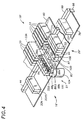
- a transport system 14 includes an input queue 16, a process queue 18 and an exit queue 20.
- a plurality of sample racks generally denoted 33 are disposed on the input queue 16 which is provided having a generally rectangular shape.
- Each of the sample racks 33 is adapted to hold a plurality of sample-containing test tubes generally denoted 34 and thus the sample racks 33 allow multiple test tubes 34 to be simultaneously moved from the input queue 16 to the process queue 18 and from the process queue 18 to the output queue 20.
- one or more sample racks 33 may be placed by a user in any location on the input queue 16. While sample racks 33 are being moved along the input queue 16, the user can remove or arrange the sample racks 33 in a random or a predetermined order.
- the input queue 16 is typically an area of the automated analyzer instrument 10 (FIG. 1) which is highly accessible to a user.
- the input queue 16 is provided from a tray 38 having a rectangular shape and having a width W corresponding to an exemplary distance typically of about 5.2 inches and an exemplary length L corresponding to a distance typically of about 17.5 inches.
- the width W of the tray 38 should be selected to accommodate the length of the sample racks 33 and the length of the tray L should be selected to accommodate a number of sample racks 33.
- the sample racks 33 are loaded onto a first surface of the tray 38a such that a handle 39 of each of the sample racks 33 is positioned at a side of the tray 38 proximate the user.
- the handle 39 allows a user to easily hold and thus move and arrange sample racks 33 on the tray 38.
- the tray 38 includes a raised central portion 42 extending its length.
- the raised central portion 42 serves as a guide along which the sample-rack 33 travels as the sample rack 33 moves from a first end to a second end of the input tray 38 (left to right in the figure).
- the guide 42 may be provided as a piece separate from the tray 38, or preferably, the guide 42 may be provided as an integral part of the tray 38 as by plastic injection molding or stamping in aluminum.
- the guide 42 should be provided having a height selected to insure that the sample rack 33 does not catch on or become entangled on the guide 42.
- the tray 38 further includes a back edge guide 44 which engages a slot 46 in the back-end of the sample rack 33 to prevent the sample rack 33 from becoming dislodged from the tray 38 and to prevent the rack from tipping.
- the tray 38 is relatively easy to clean. Cleaning of the tray 38 is further unimpeded by sample rack positioning structures. This also allows the sample racks 33 to be arbitrarily loaded onto, removed from or rearranged on the tray 38 without interruption of the operation of the transport system 14.
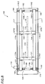
- the process queue 18 is disposed adjacent the input queue 16 such that sample racks 33 may be conveniently and easily moved from the end of the input queue 16 to the process queue 18.
- the process queue 18 is mounted on a movable carrier member 52.
- a support block 54 Disposed on the carrier member 52 is a support block 54 which may be provided, as an aluminum member having a square cross-sectional shape and having a thickness typically of about one inch.
- the support block 54 supports a slide 58 a predetermined distance above the carrier member 52, and provides additional structural support to the carrier member 52.
- a drive 53 is coupled to move the process queue 18 in response to signals from controller 28.
- a process tray 60 mounts on the slide 58 to move on linear bearings mounted on a bottom surface of the process tray 60.
- the process tray 60 is provided having a plurality of equally spaced dividing walls 61 projecting from a base surface thereof.
- the dividing walls 61 form a plurality of slots 64 in which sample racks 33 may be held.
- An infeed apparatus 51 is mounted at a predetermined position on the input queue 16.
- the infeed apparatus 51 is mounted at an end of the tray 38.
- the infeed apparatus 51 which will be described in detail below in conjunction with FIGS. 3 and 4, moves the sample rack from the load position at the far end of the input queue 16 to an empty slot 64 of the process queue 18.
- the process tray 60 is directed by controller 28 to a position to insure that an empty slot 64 is available to receive the sample rack 33 provided by the infeed apparatus 51.
- the input queue 16 is selected having a tray long enough to hold twenty sample racks 33.
- each sample rack 33 holds five test tubes 34.
- Each of the test tubes 34 have a bar code label attached thereto.
- the test tubes 34 are oriented in the sample rack 33 such that the affixed bar code label is exposed to a bar code reader 83 disposed proximate a load position 22 of the input queue 16, where sample racks are moved out of the process queue.
- the infeed mechanism 51 is here shown to include a belt 84 endlessly circulating around a pair of pulleys 86a, 86b. As may be more clearly seen in FIG. 4, a first one of the pulleys 86a is coupled to a bidirectional motor 104 such as a stepper motor.
- a plurality of outwardly extending paddles or profiles 88, 88a-88b coupled to the belt 84 are a plurality of outwardly extending paddles or profiles 88, 88a-88b.
- the profiles 88 are placed on a portion only of the belt 84.
- the locations of the end profiles 88a, 88h are selected such that a sample rack 33 can be positioned in the load position 22 between them while the profiles 88b-88h prevent a sample rack 33a adjacent the load position 22 from entering the load position as a rack is moved off between profiles 88a and 88h.
- a load position guide 89 Coupled to the input queue 16 proximate the load position 22 is a load position guide 89.
- the load position guide 89 prevents tipping of the sample rack in the load position 22.
- the load position is available to accept a sample rack 33.
- the sample rack 33 which was adjacent the profiles 88 is then moved into the space of load position 22 where its presence is sensed by a sensor as described below.
- the motor 104 (FIG. 4) then drives the belt 84 and profiles 88 in a clockwise direction. Coupled to profile 88a is an aluminum block 90 which contacts a first end of the sample rack 33 which is now placed in the load position 22 of the input queue 16. As the belt 84 moves in a clockwise direction, the sample rack 33a is pushed from the load position 22 of the input tray 38 to an open slot 64 in the process queue 18 by controller 28.
- Block 90 extends the distance which the surface contacting the end of the sample rack 33 travels ensuring that the sample rack 33 is pushed completely off the input queue 16 and completely on to the process queue 18.
- the process queue 18 accepts the sample racks 33 fed thereto by the infeed mechanism 51. As described above, the process queue 18 moves linearly along a track such that sample racks 33 from the input queue 16 may be fed into different spaces 64 of the process queue 18. Also the process queue 18 moves along the track to align particular sample racks 33 with the exit pusher 72 under control of controller 28.
- a sensor 98 at an end of the exit queue 20 indicates to the controller 28 when the exit queue 20 fills with sample racks 33 a signal and either notify a user to take some action such as removing sample racks 33 from the exit queue 20 and/or prevent any additional sample racks 33 from being moved from the process queue 18 to the exit queue 20 until space is made available on the exit queue 20.
- the sensor may be disposed on a top or bottom surface of the tray 78.
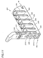
- the transport system 14 also has an emergency sample rack entry queue 105.
- Entry queue 105 includes a stat-entry position 101, a stat sensor 102 and a stat-load position 103.
- the purpose of the stat-entry queue 105 is to allow a user to have the analyzer system 10 perform a test out of order as soon as possible on any samples loaded the in stat-entry queue 105.
- the transport system 14 further includes the bar code reader 83 disposed proximate the stat-entry position 101. Portions of the bar code reader 83 have here been removed to allow a clearer view of the pusher bar 106 and pusher block 108.
- the bar code reader 83 is held in a fixed position above the pusher block 108 by a mounting member 109 which may be provided as a mounting bracket for example.
- the bar code reader 83 is preferably positioned such that it can read bar codes on labels attached to the test tubes being moved to the process queue 18 from either the load position 22 (FIG. 3) on input queue 16 or from the stat-load position 103.
- the bar code labels move past the bar code reader 83 and the bar code reader 83 decodes the information from the bar code label and sends such information to the system controller 28 (FIG. 1).
- This information may include, patient, sample, and other direct fluid data. Tests to be run on each sample are entered separately into controller 28. Some samples may be identified for "batch runs" meaning a specified set of tests for all specimens in the batch.
- a magnetic conveyor 110 is provided for the input queue 18.
- the drive system 116 includes first and second drive belts 117 disposed around a pair of pulleys 118a, 118b, driven by a drive motor 119. Belts 117 are placed near front and back portions of tray 38
- the drive motor 119 is here provided as a stepper motor 119 having a drive gear 123 coupled to pulley 118b which is provided as a pulley gear 118b (FIG. 5B).
- the coupling is accomplished with a 2:1 gear reduction ratio.
- the drive motor 119 may be disposed below the transport tray 38 and coupled to pulley 118a via a drive belt 120.
- a plurality of magnet assemblies 121a-121e are coupled to each drive belt 117.
- the magnet assemblies 121a-121e are equally spaced apart by a predetermined distance.
- the tray 38 is spaced a predetermined distance above the belt 117 such that the magnet assemblies 121a, 121c and 121e as shown in FIG. 5, pass under the tray 38 a predetermined distance.
- Each magnet assembly 121a-121e includes a magnet having a magnetic force of sufficient strength such that a magnetic force is present at least at, and in this embodiment preferably above, the surface 114a of the tray 78.
- the sample racks 33 include a magnetically attractive region engageable by the magnetic force of magnet assemblies 121.
- the magnet assemblies 121 thus magnetically couple the sample racks 33 to the drive system such that drive system moves the sample racks 112 along the surface of the tray 38.
- each magnet assembly 121a-121e is driven around the pair of pulleys 118 via the belt 117 and move the sample racks 112 along the transport tray 114.
- the distance by which the magnet assemblies 121 are spaced from each other is selected in accordance with a variety of factors including but not limited to the number of sample racks 33 each individual magnet assembly 121 can move.
- each magnet assembly 121 is of a magnetic strength sufficient to move several sample racks 33.
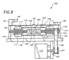
- the conveyor system 110 further includes a sensor 124 coupled to a base plate 126 and disposed below a surface of the belt 117.
- the sensor 124 may be provided as a Hall effect sensor, for example, and is disposed to provide a signal whenever a magnet assembly 121 passes thereover. The sensor 124 thus indicates the position of a magnet assembly 121. Since the location of each of the magnet assemblies 121a-121e on the belt 117 with respect to the other is known, when the location of one of the magnet assemblies 121 is known, the location of each of the magnet assemblies 121 is known.
- the transport system 110 further includes a load position sensor 128 which may, for example, be provided as an optical sensor which detects light reflected from a surface of a sample rack 33 adjacent it.
- a load position sensor 128 which may, for example, be provided as an optical sensor which detects light reflected from a surface of a sample rack 33 adjacent it. In operation, as a sample rack 33 moves into the load position in front of profile 88a, light reflects off a surface 201 (Fig. 10) of the sample rack 33 and activates the load position sensor 128.
- the drive motor 119 coupled to pulley 129 turns the belt 117 in a clockwise direction until, typically three magnet assemblies 121 pass by the sensor 124. This step ensures that any sample rack 33 positioned on the left most side of the tray 38 travels the entire length of the tray 114.
- the drive motor 119 then turns the belt 117 in a counterclockwise direction by a predetermined short distance typically 0.06 in.) to relieve any pressure applied to a sample rack in the load position due to an adjacent sample rack .
- a predetermined short distance typically 0.06 in. typically 0.06 in.
- the drive system here provided from the belt 117, pulleys 118 and motor 119 is completely independent of the tray 38 and magnet assemblies 121.
- the drive system 116 may be alternatively implemented by any means for moving the magnet assemblies 121 such as electromagnetic means or other means.
- the magnet assemblies may be provided as having electromagnets which may be turned on and off to attract the magnetically attractive regions of the sample racks.
- electromagnets may be moved via a conveyor type belt similar to belt 117 or via pusher rods which move back and forth in a linear direction below the tray. With the pusher rod approach the electromagnets would be activated as the push rods move the magnets and thus sample racks from a position distal to the load position to a position proximate the load position. The electromagnets would then be de-activated prior to the push rods retracting the electromagnets from the load position. Furthermore, with the input tray completely filled, in the case where electromagnets are used on belt 117, it need not be turned off to prevent magnet forces from continuously pushing against the sample racks, rather, the electromagnets may be turned off.
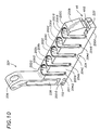
- FIG. 6 a portion of the magnetic conveyor 110 described above in conjunction with FIG. 5, is shown having three sample racks 33 disposed thereon. Top portions of each of the sample racks 33 have been removed to reveal test tubes 130 disposed in each of the sample racks. A bottom portion of the sample rack 33, has been cut away to expose in section, a plate 134 disposed in a bottom portion of the sample rack 33.
- the plate 134 may be provided from any magnetically attractive material.
- the plate 134 is provided from magnetic stainless steel having a thickness typically of about .125 inches. In alternate embodiments, however, other materials such as iron, non-stainless steel or even a magnet material may also be used. In the event that plate 134 is provided from a magnet material care should be taken to ensure that a magnetic pole of plate 134 is not in opposition to a magnetic pole of magnet assembly 121.
- the magnet assemblies 121 include an aluminum housing 136 having a thickness typically of about .090 inches over which shown in section, a backing plate 138, a bar magnet 140 and a magnet cover 142, are disposed.
- the backing plate 138 is provided from magnetic stainless steel and is provided having a thickness typically of about .060 inches.
- the magnet 140 may be provided as a neodymium-iron-boron magnet having a thickness typically of about .250 inches and the magnet cover 142 may be provided from a plastic material such as Acetal or any similar material having a thickness typically of about .040 inches.
- the magnet assembly 121 is coupled to a profile 144 projecting from a surface of the belt 117.
- the profile 144 may be similar to the profiles 88 described above in conjunction with FIGs. 3 and 4.
- the magnet assemblies 121 can be coupled to the profile 144 via screws which pass through clearance holes provided in the profile 144 and mate with threaded holes provided in the aluminum housing 136 or may be fastened to the profile 144 via epoxy or welding techniques well known to those of ordinary skill in the art.
- the tray 38 is, in this embodiment, provided from an aluminum sheet having a thickness typically of about .0625 inches.
- the surface of the aluminum sheet on which the sample racks 33 are disposed is provided having a polytetrafluorethylene type of coating, such as Teflon® disposed thereon to reduce frictional forces between the tray 38 surface and the contacting surface of the sample racks 33.
- Teflon® a polytetrafluorethylene type of coating
- FIG. 7 a portion of the conveyor system 110 is shown having sample rack 33 disposed in the load position of an input queue.
- the load position corresponds to a channel defined on one side by a shoulder 38c of the tray 38.
- a load position guide 150 is disposed proximate the load position. In operation, as the sample rack 33 is moved into the load position of the input queue, the load position guide 150 engages a slot 152 formed in the front end of the sample rack 33. The guide 150 ensures that the sample rack 112 is properly aligned in the load position.
- the sensor 128 sends a signal which under control of controller 38 activates the infeed apparatus 51 and causes the belt 84 to turn the profile 88a and member 90 (FIG. 3) to drive the sample rack 33 onto the process queue.
- the profile 88a is provided having a height H typically of about one inch, a width W typically of about .750 inches and a thickness T typically of about .125 inches.
- a bottom edge 89 of profile 88a is spaced a predetermined distance from the top surface of the tray 38, typically of about .25 inches.
- the magnet assembly 121 is coupled to the profile 144 projecting from the belt 117. As the magnet assembly 121 approaches the end of the tray 38 proximate the profiles 88 and pulley 118a, the magnet assembly 121 is extended past the end of the pulley 118a, insuring that the sample rack 33 is moved completely into the load position of the tray 38. Thus, by coupling the magnet 140 to the profile 144 as described above, the magnet assembly 121 moves the sample rack 33 past the end of the belt 117 as it rounds the pulley 118a.
- the pulleys 118a or 118b have sets of teeth to engage corresponding recesses in the belt 117 to preserve indexing.
- the pulleys 118 turn to move the belt 117 an additional distance to move any other sample racks 33 on the tray 114 toward the load position.
- the belt 117 stops moving, with one of magnet assemblies 121 positioned by controller 28 under the sample rack which is next in line to be moved to the load position when the belt 112 executes a short move back away from the load position, the sample rack 37 in the load position remains in the load position while the other sample racks 33 moves away slightly to prevent jamming at the load position.
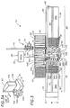
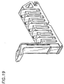
- the drive assembly 116 is shown to include a pair of like stainless steel shafts 162, 164 spaced apart and disposed at opposing ends of tray 114.
- shaft 164 each end of the shaft 164 is coupled to a ball bearing assembly 166 mounted as shown in respective ends of mounting plates 167a, 167b generally denoted 167 extending below tray 114.
- the ball bearing assemblies 166 allow the shafts 162, 164 to rotate relative to the mounting plates 167.
- Each shaft 162, 164 has mounted thereon the paired drive pulleys 118a, 118b. Disposed adjacent one belt pulley 118b is a drive gear 123.
- an alternate drive pulley 176 is coupled to a shaft 164, and driven by a drive motor 177 the through shaft 122, pulley 181 and belt 180.
- the drive shaft 162 is here provided from a pair of shafts 192, 194 held together by a combination of shoulder regions 196 and a locking collar 198.
- the shafts 162, 164 can be easily assembled and disassembled to allow easy access for repair and replacement.
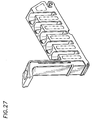
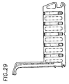
- a sample rack 200 corresponding to rack 33 has first and second opposing ends 200a, 200b, a top surface 200c, a bottom surface 200d (FIG. 14) and a pair of opposing side surfaces 200e, 200f (FIG. 16).
- An optional reflective member 201 is disposed on surface 200e.
- the reflective member, 201 reflects light to activate optical sensor 128 (FIG. 5).
- the reflective member can be disposed along any portion of surface 200e where it may be aligned to activate sensor 128.
- member 201 is omitted (FIG. 11) and surface 200e is made of a reflective material or polished such that light incident thereon is reflected and activates sensor 128.
- a plurality of openings 202a-202e are formed in top surface 200c of rack 200 in the typical case there are five openings.
- the openings 202a-202e are provided having a shape selected to accept a sample containing vessel.
- the openings 202 are provided having a circular shape selected to accommodate test tubes in a range of sizes.
- Each of the openings 202a-202e has a corresponding slot 204a-204e formed in the side surface 200e of the sample rack 200.
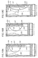
- FIGS. 18A-C are section views down the middle of a slot 204 of a sample rack 33 showing installation and compression in use, holding a test sample container 34, of a spring 206.
- a spring 206 At the rear of each slot 204 are top and bottom lipped spring retaining grooves 203 and 205 respectively.
- the grooves are formed by ridges 207 that are formed on each side of the slot 204 creating two grooves 203 and 205.
- the springs 206 have rolled ends 208 which aid in retaining the spring in the rack by slipping over the tips of grooves 203 and 205.
- the normal unstressed position of the spring 206 is shown in FIG. 18A.
- the bottom end 208 fails to reach grooves 205 until this spring is extended during installation so that lower rolled end 208 falls into grooves 205.
- spring 206 is stressed further under a force 211 extending the bottom end 208 downward into a slack accommodation extension 213 of groove 205.
- tube removal spring 206 returns to the state of FIG. 18B.
- sample racks can hold test tubes having a range of diameters, it should also be noted that within this range it is preferable to place test tubes having similar diameters in the same sample rack. Thus, and as will be described further below, while each sample rack can hold test tubes having a diameter in the range of 10.25-16.5 mm it may be desirable to designate particular racks to hold test tubes having diameters within a particular range.
- the front end of the sample rack has load slot 152 formed therein.
- the load slot 152 accepts the load guide 150, (FIGs. 7 and 9 respectively) to thus properly align the sample rack 200 in the load position of the input queue.
- the back end of the sample rack 200 has opening 46 which mates with the input queue edge guide 48 (FIGs. 2, 3) and exit queue edge guide 99 (FIGs. 2, 3).
- the opening 46 includes a raised portion 222 which engages a corresponding shape on the input queue guide 48 which assists in locating the sample rack 200 on the input queue and prevents the rack 200 from tipping over or sliding off of the input queue.
- the back edge guide 99 is provided as an L-shaped member.
- the guide 99 thus mates only with a front portion 46a of the opening 46 such that the racks may be easily removed from the exit queue.
- the sample rack 200 also includes a handle 224 with which a user may carry the sample rack 200.
- a top angled portion of the handle has a depression 226 formed therein to lend an ergonomic design which is comfortable for a user to grasp.
- the handle 224 also has a side surface 228 on which may be attached a vertical bar code label 229.
- the vertical bar code label 229 has a plurality of barcodes disposed thereon.
- the barcodes identify the size (e.g. diameter range) of test tubes which are accommodated in the sample rack 200.
- a sliding clip 233 is disposed around the handle 224 of the sample rack 200 and a user arranges the clip 233 to indicate the size of test tube actually disposed in the sample rack 200.
- a further barcode region 230 identifies the sample rack serial number. Thus each individual sample rack has its own unique identifying number.
- the barcode reader In operation, when the sample rack 200 is moved from the input queue to the process queue the barcode reader reads the barcode on label 228 which are either not blocked by or are emphasized by the sliding clip 233. Thus the barcode reader can identify the type (i.e. the size) of the test tube disposed in the sample rack 200. As mentioned above the sample rack 200 is able to hold test tubes having different diameters and shapes. However, to improve alignment at the sample probe with the opening of the test tube, the system controller preferably knows the type of the test tube.
- the entire sample rack 200 including handle 224 may be provided as a single piece via injection molding techniques.
- the test tube carrying portion of the sample rack 200 and the handle 224 may be provided as separate pieces and mated together via screws, epoxy, or any other fastening technique well known to those of ordinary skill in the art.
- a pair of screws in holes 231a, 231b secure the handle 224 to the base portion of the sample rack 200 via screws 231c, not shown.
- each of the holes 202 may optionally be provided with slots 225 formed in the bottom thereof to stabilize the test tube in the holes 202.
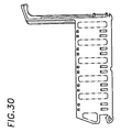
- the bottom surface of the sample rack 200 has a grove 234 formed therein which mates with and accommodates the guides 42, 80 (FIG. 2) of the input and exit queues.
- the bottom surface of the sample rack 200 also has formed therein a pair of rectangular shaped cavities 240 (FIG. 13).
- a magnetically attractive member 244 (FIG. 15) is disposed in each of the cavities 240.
- the magnetically attractive member may be molded into the bottom surface of the sample rack.
- a cover 246 may likewise be fastened to the sample rack over member 244.
- the members 244 are symmetrically disposed about a latitudinal center line 245 of the sample rack 200.
- each of the magnetically attractive members 244 is provided as a magnetically attractive stainless steel plate having a generally rectangular shape. As may be more clearly seen in FIG. 15, a first portion 244c of the bottom surface is slightly recessed from (or substantially aligned with) the bottom surface of the sample rack 200. A second portion 244b of the plate 244 angles into the rack 200 body as discussed above.
- a magnet assembly 121 approaches the sample rack from a direction such that the magnet first attracts the angled second portion 244b of the member 244.
- the force of the magnetic field provided from the magnet assembly 120 (FIG. 6) is gradually introduced to the member 244.
- a pair of covers 246 are disposed over the openings 240.
- the covers 246 fit into grooves 247 (FIG. 15) formed proximate the openings 240.
- the covers 246 are selected to have a size and shape such that the cover 246 forms a snap fit in the openings 240 to thus secure the plates 244 in the rack 200 while leaving exposed at least a portion of the member 244 (FIG. 14).
- sample rack members 244 are spaced apart and positioned in the bottom surface of the sample rack 200 such that when the sample rack 200 is placed on a tray of a conveyor system such as the conveyor system of FIG. 8, the magnet assemblies 173, (FIG. 8) coupled to the belts 170a, 170b (FIG. 8) pass directly under the members 244.
- a pair of raised portions or rails 250, 252 Projecting from a bottom surface of the sample rack 200 are a pair of raised portions or rails 250, 252.
- the rails 250, 252 space the bottom surface of the sample rack along with member 244 from the queue surface and thus the member 244 from a surface on which the racks are placed.
- the rails 250, 252 decrease the surface area of the sample rack 200 which contacts, for example, the surface of the tray 114 (FIGs. 5, 6) on which the rack 200 is placed. Consequently frictional forces between the sample rack 200 and the tray 38 are reduced. This results in a lower magnetic force being required to move sample racks 200 along the tray 38.
- the drive system could be provided having a single belt and magnet coupled thereto.
- the belt and magnet would preferably be disposed along a central longitudinal axis of a transport tray.
- the sample rack would include a single magnetically attractive region disposed in the center of the sample rack and aligned with the single belt and magnet when the sample rack is placed on the transport tray.
- the plate could be provided having different thicknesses on each end.
- a first end of the plate could be relatively thin and a second end of the plate could be relatively thick.
- a magnet coupled to a drive system would first encounter the thin end of the plate. This would result in a relatively weak magnetic coupling. The magnet would then engage the thick end of the plate with a relatively strong force. With this arrangement, the sample rack would smoothly transition from a stationary state to a moving state.
Landscapes
- Chemical & Material Sciences (AREA)
- Health & Medical Sciences (AREA)
- General Health & Medical Sciences (AREA)
- Life Sciences & Earth Sciences (AREA)
- Analytical Chemistry (AREA)
- Biochemistry (AREA)
- Physics & Mathematics (AREA)
- General Physics & Mathematics (AREA)
- Immunology (AREA)
- Pathology (AREA)
- Clinical Laboratory Science (AREA)
- Chemical Kinetics & Catalysis (AREA)
- Automatic Analysis And Handling Materials Therefor (AREA)
- Non-Mechanical Conveyors (AREA)
Priority Applications (1)
| Application Number | Priority Date | Filing Date | Title |
|---|---|---|---|
| EP03075707A EP1326077B1 (de) | 1995-07-14 | 1996-07-12 | Probentransportsystem mit Magneten |
Applications Claiming Priority (2)
| Application Number | Priority Date | Filing Date | Title |
|---|---|---|---|
| US08/502,653 US5720377A (en) | 1995-07-14 | 1995-07-14 | Magnetic conveyor system |
| US502653 | 1995-07-14 |
Related Child Applications (1)
| Application Number | Title | Priority Date | Filing Date |
|---|---|---|---|
| EP03075707A Division EP1326077B1 (de) | 1995-07-14 | 1996-07-12 | Probentransportsystem mit Magneten |
Publications (3)
| Publication Number | Publication Date |
|---|---|
| EP0753748A2 true EP0753748A2 (de) | 1997-01-15 |
| EP0753748A3 EP0753748A3 (de) | 1998-01-07 |
| EP0753748B1 EP0753748B1 (de) | 2004-05-06 |
Family
ID=23998778
Family Applications (2)
| Application Number | Title | Priority Date | Filing Date |
|---|---|---|---|
| EP03075707A Expired - Lifetime EP1326077B1 (de) | 1995-07-14 | 1996-07-12 | Probentransportsystem mit Magneten |
| EP96305159A Expired - Lifetime EP0753748B1 (de) | 1995-07-14 | 1996-07-12 | Probenfördereinrichtung |
Family Applications Before (1)
| Application Number | Title | Priority Date | Filing Date |
|---|---|---|---|
| EP03075707A Expired - Lifetime EP1326077B1 (de) | 1995-07-14 | 1996-07-12 | Probentransportsystem mit Magneten |
Country Status (6)
| Country | Link |
|---|---|
| US (1) | US5720377A (de) |
| EP (2) | EP1326077B1 (de) |
| JP (1) | JP3880658B2 (de) |
| CA (1) | CA2178257A1 (de) |
| DE (2) | DE69632366T2 (de) |
| MX (1) | MX9602319A (de) |
Cited By (16)
| Publication number | Priority date | Publication date | Assignee | Title |
|---|---|---|---|---|
| WO2001070050A1 (fr) * | 2000-03-20 | 2001-09-27 | Barriquand Steriflow | Installation de sterilisation en continu de produits contenus dans des emballages souples |
| WO2005107438A1 (de) * | 2004-04-16 | 2005-11-17 | Bartec Gmbh | Anordnung zur automatischen probenahme an milchsammelwagen und melkanlagen |
| WO2005107439A1 (de) * | 2004-04-16 | 2005-11-17 | Bartec Gmbh | Anordnung und verfahren zur automatischen probenahme an milchsammelwagen und melkanlagen |
| WO2005114133A1 (de) * | 2004-05-07 | 2005-12-01 | Bartec Gmbh | Anordnung und verfahren zur automatischen probenahme an milchsammelwagen und melkanlagen |
| KR100705086B1 (ko) | 2004-04-26 | 2007-04-06 | 가부시키가이샤 아이디에스 | 바코드 판독 장치 |
| KR100705078B1 (ko) | 2004-04-05 | 2007-04-06 | 가부시키가이샤 아이디에스 | 바코드 판독 장치 |
| EP2108452A1 (de) * | 2008-04-02 | 2009-10-14 | Danmarks Tekniske Universitet (DTU) | Einstellbarer Chiphalter |
| EP2749356A3 (de) * | 2010-07-23 | 2014-10-08 | Beckman Coulter, Inc. | System oder Verfahren zur Aufnahme analytischer Einheiten |
| CN106829473A (zh) * | 2017-02-09 | 2017-06-13 | 中江县凯讯电子有限公司 | 一种网络变压器送料设备的使用方法 |
| CN108479891A (zh) * | 2018-07-09 | 2018-09-04 | 陈羽戈 | 一种机械自动化装载试管架装置 |
| WO2018232364A1 (en) * | 2017-06-16 | 2018-12-20 | Beckman Coulter, Inc. | Apparatus and method for handling sample containers |
| EP3361261A4 (de) * | 2015-10-07 | 2019-06-26 | Jeol Ltd. | Übertragungsvorrichtung für probenrack und automatisches analysesystem |
| USD885605S1 (en) | 2016-07-28 | 2020-05-26 | Beckman Coulter, Inc. | Sample tube rack |
| US10919043B2 (en) | 2015-11-16 | 2021-02-16 | Beckman Coulter, Inc. | Sample tube rack and sample tube analysing system |
| USD938612S1 (en) | 2017-06-16 | 2021-12-14 | Beckman Coulter, Inc. | Sample rack |
| WO2022007301A1 (zh) * | 2020-07-07 | 2022-01-13 | 深圳市亚辉龙生物科技股份有限公司 | 样本架传送装置及体外诊断设备 |
Families Citing this family (117)
| Publication number | Priority date | Publication date | Assignee | Title |
|---|---|---|---|---|
| EP2082806A3 (de) * | 1998-05-01 | 2010-04-28 | Gen-Probe Incorporated | Automatisches Diagnoseanalysegerät und Verfahren |
| US8337753B2 (en) | 1998-05-01 | 2012-12-25 | Gen-Probe Incorporated | Temperature-controlled incubator having a receptacle mixing mechanism |
| US6193892B1 (en) | 1999-03-03 | 2001-02-27 | Promega Corporation | Magnetic separation assembly and method |
| US6919044B1 (en) * | 1999-06-17 | 2005-07-19 | Beckman Coulter, Inc. | Sample loading and handling interface to multiple chemistry analyzers |
| IT1309303B1 (it) * | 1999-06-30 | 2002-01-22 | Gd Spa | Macchina impacchettarice di sigarette. |
| US6571934B1 (en) | 2001-11-14 | 2003-06-03 | Dade Behring Inc. | Bi-directional magnetic sample rack conveying system |
| JP4256136B2 (ja) * | 2002-10-01 | 2009-04-22 | 株式会社小糸製作所 | 車両用灯具 |
| US20050071110A1 (en) * | 2003-09-25 | 2005-03-31 | Davis Randall R. | Method for identifying objects to be used in an automatic clinical analyzer |
| US7331474B2 (en) * | 2004-03-05 | 2008-02-19 | Beckman Coulter, Inc. | Specimen-container rack for automated clinical instrument |
| US7850914B2 (en) * | 2004-03-05 | 2010-12-14 | Beckman Coulter, Inc. | Specimen-transport module for a multi-instrument clinical workcell |
| JP4469964B2 (ja) * | 2004-03-05 | 2010-06-02 | ベックマン・コールター・インコーポレーテッド | 自動化された臨床機器のための磁気吸引検体−容器ラック |
| US7028831B2 (en) * | 2004-03-05 | 2006-04-18 | Beckman Coulter, Inc. | Magnetic specimen-transport system for automated clinical instrument |
| AT501313B1 (de) | 2005-02-01 | 2009-07-15 | Stiwa Holding Gmbh | Haltevorrichtung für zylindrische gegenstände, insbesondere rohrförmige probenbehälter |
| CA2871777C (en) * | 2005-03-10 | 2015-07-28 | Matthew J. Hayes | System and methods for detecting multiple optical signals |
| DE102007014876B4 (de) * | 2007-03-26 | 2010-04-08 | Kba-Metronic Aktiengesellschaft | Transportsystem |
| TWI325337B (en) * | 2007-07-26 | 2010-06-01 | Ind Tech Res Inst | Magnetic separation device |
| JP5289798B2 (ja) * | 2008-03-07 | 2013-09-11 | シスメックス株式会社 | 分析装置および検体の搬送方法 |
| IT1390719B1 (it) * | 2008-07-16 | 2011-09-15 | Dachi S R L | Procedimento per la gestione di campioni urgenti all'interno di un impianto di automazione |
| DE502008002888D1 (de) * | 2008-09-09 | 2011-04-28 | Siemens Ag | Transfervorrichtung mit dynamisch veränderbaren Antriebsbereichen |
| JP5468250B2 (ja) * | 2008-12-11 | 2014-04-09 | ベックマン コールター, インコーポレイテッド | ラック搬送システム |
| JP2010139370A (ja) * | 2008-12-11 | 2010-06-24 | Beckman Coulter Inc | ラックトレイ、ラックおよびラック搬送システム |
| WO2010132823A2 (en) | 2009-05-15 | 2010-11-18 | Biomerieux, Inc. | System and methods for rapid identification and/or characterization of a microbial agent in a sample |
| CN104774754B (zh) * | 2009-05-15 | 2017-11-17 | 生物梅里埃有限公司 | 用于微生物检测设备的自动化加载机构 |
| DE102010028769A1 (de) | 2010-05-07 | 2011-11-10 | Pvt Probenverteiltechnik Gmbh | System zum Transportieren von Behältern zwischen unterschiedlichen Stationen und Behälterträger |
| US9046507B2 (en) | 2010-07-29 | 2015-06-02 | Gen-Probe Incorporated | Method, system and apparatus for incorporating capacitive proximity sensing in an automated fluid transfer procedure |
| US8718948B2 (en) | 2011-02-24 | 2014-05-06 | Gen-Probe Incorporated | Systems and methods for distinguishing optical signals of different modulation frequencies in an optical signal detector |
| CN103547926B (zh) | 2011-05-13 | 2016-08-31 | 贝克曼考尔特公司 | 实验室产品传送元件和路径布置 |
| CN103518137B (zh) | 2011-05-13 | 2016-09-07 | 贝克曼考尔特公司 | 包括实验室产品传送元件的系统和方法 |
| CN102393467B (zh) * | 2011-08-02 | 2013-06-05 | 英科新创(厦门)科技有限公司 | 一种血液筛查联合检测仪 |
| CN102360019B (zh) * | 2011-08-16 | 2013-05-22 | 杨晓勇 | 一种应用于全自动化学发光分析仪的样本架传送与推动装置 |
| EP2589966A1 (de) | 2011-11-04 | 2013-05-08 | Roche Diagnostics GmbH | Laborprobenverteilungssystem und entsprechendes Betriebsverfahren |
| EP2589968A1 (de) | 2011-11-04 | 2013-05-08 | Roche Diagnostics GmbH | Laborprobenverteilungssystem, Laborsystem und Betriebsverfahren |
| EP2589967A1 (de) * | 2011-11-04 | 2013-05-08 | Roche Diagnostics GmbH | Laborprobenverteilungssystem und entsprechendes Betriebsverfahren |
| WO2013070754A1 (en) | 2011-11-07 | 2013-05-16 | Beckman Coulter, Inc. | Robotic arm |
| KR20140092375A (ko) | 2011-11-07 | 2014-07-23 | 베크만 컬터, 인코포레이티드 | 원심분리기 시스템 및 작업 흐름 |
| BR112014011043A2 (pt) | 2011-11-07 | 2017-06-13 | Beckman Coulter Inc | detecção de recipiente de espécime |
| KR20140091032A (ko) * | 2011-11-07 | 2014-07-18 | 베크만 컬터, 인코포레이티드 | 검체 수송 시스템의 자기 감쇠 |
| WO2013070740A1 (en) | 2011-11-07 | 2013-05-16 | Beckman Coulter, Inc. | Aliquotter system and workflow |
| EP2776848B1 (de) | 2011-11-07 | 2019-12-25 | Beckman Coulter, Inc. | System und verfahren zum transport von probenbehältern |
| DE102011090044A1 (de) * | 2011-12-28 | 2013-07-04 | Siemens Healthcare Diagnostics Products Gmbh | Transportsystem und Verfahren zum Betrieb |
| US9316659B2 (en) | 2012-05-11 | 2016-04-19 | Siemens Healthcare Diagnostics Inc. | Method and system for transporting sample tubes |
| BR112015005346A2 (pt) | 2012-09-14 | 2017-07-04 | Beckman Coulter Inc | sistema analítico com transporte capilar |
| WO2014144759A1 (en) | 2013-03-15 | 2014-09-18 | Abbott Laboratories | Linear track diagnostic analyzer |
| EP2972402B1 (de) | 2013-03-15 | 2023-12-20 | Abbott Laboratories | Diagnostische analysevorrichtung und vorbehandlungskarussells und zugehörige verfahren |
| US9513303B2 (en) | 2013-03-15 | 2016-12-06 | Abbott Laboratories | Light-blocking system for a diagnostic analyzer |
| EP2972403B1 (de) | 2013-03-15 | 2022-12-07 | Abbott Laboratories | Automatisierte diagnostische analysevorrichtungen mit vertikal angeordneten karussellen und zugehörige verfahren |
| CN114137240A (zh) | 2013-03-15 | 2022-03-04 | 雅培制药有限公司 | 具有后面可进入轨道系统的自动化诊断分析仪及相关方法 |
| EP2972219B1 (de) | 2013-03-15 | 2022-01-19 | Abbott Laboratories | Automatisierter reagensmanager eines diagnostischen analysatorsystems |
| FR3012437B1 (fr) * | 2013-10-25 | 2015-10-23 | Biomerieux Sa | Dispositif, systeme et procede de convoyage d'un objet |
| CN104741162B (zh) * | 2013-12-31 | 2018-05-25 | 深圳迈瑞生物医疗电子股份有限公司 | 分析仪流水线的试管架及其移位检测方法和装置 |
| US11181539B2 (en) | 2013-12-31 | 2021-11-23 | Shenzhen Mindray Bio-Medical Electronics Co., Ltd. | Shift detection method and analyzer pipeline |
| DE102014202843B3 (de) | 2014-02-17 | 2014-11-06 | Roche Pvt Gmbh | Transportvorrichtung, Probenverteilungssystem und Laborautomatisierungssystem |
| DE102014202838B3 (de) | 2014-02-17 | 2014-11-06 | Roche Pvt Gmbh | Transportvorrichtung, Probenverteilungssystem und Laborautomatierungssystem |
| AP2016009353A0 (en) * | 2014-02-27 | 2016-07-31 | Nanopix Integrated Software Solutions Private Ltd | An improved machine for grading small sized irregular objects and a process thereof |
| EP2927695B1 (de) | 2014-03-31 | 2018-08-22 | Roche Diagniostics GmbH | Probenverteilungssystem und Laborautomatisierungssystem |
| EP2927168A1 (de) | 2014-03-31 | 2015-10-07 | Roche Diagniostics GmbH | Transportvorrichtung, Probenverteilungssystem und Laborautomatisierungssystem |
| EP2927167B1 (de) | 2014-03-31 | 2018-04-18 | F. Hoffmann-La Roche AG | Versandvorrichtung, Probenverteilungssystem und Laborautomatisierungssystem |
| EP2927163B1 (de) | 2014-03-31 | 2018-02-28 | Roche Diagnostics GmbH | Vertikalfördervorrichtung, Probenverteilungssystem und Laborautomatisierungssystem |
| EP2927625A1 (de) | 2014-03-31 | 2015-10-07 | Roche Diagniostics GmbH | Probenverteilungssystem und Laborautomatisierungssystem |
| EP2957914B1 (de) | 2014-06-17 | 2018-01-03 | Roche Diagnostics GmbH | Laborprobenverteilungssystem und Laborautomatisierungssystem |
| EP2977766A1 (de) | 2014-07-24 | 2016-01-27 | Roche Diagniostics GmbH | Laborprobenverteilungssystem und Laborautomatisierungssystem |
| EP2995960B1 (de) | 2014-09-09 | 2020-07-15 | Roche Diagniostics GmbH | Laborprobenverteilungssystem und Verfahren zur Kalibrierung von magnetischen Sensoren |
| EP2995580A1 (de) | 2014-09-09 | 2016-03-16 | Roche Diagniostics GmbH | Laborprobenverteilungssystem und Laborautomatisierungssystem |
| US9952242B2 (en) | 2014-09-12 | 2018-04-24 | Roche Diagnostics Operations, Inc. | Laboratory sample distribution system and laboratory automation system |
| EP2995958A1 (de) | 2014-09-15 | 2016-03-16 | Roche Diagniostics GmbH | Verfahren zum Betrieb einer Laborprobe Verteilungssystem, Laborprobenverteilungssystems und Laborautomatisierungssystem |
| EP3006943B1 (de) | 2014-10-07 | 2020-04-22 | Roche Diagniostics GmbH | Modul für ein Laborprobenverteilungssystem, Laborprobenverteilungssystem und Laborautomatisierungssystem |
| CN104330579B (zh) * | 2014-10-20 | 2015-09-30 | 深圳市新产业生物医学工程股份有限公司 | 样本架传输装置 |
| EP3016116A1 (de) | 2014-11-03 | 2016-05-04 | Roche Diagniostics GmbH | Leiterplattenanordnung, Spule für ein Laborprobenverteilungssystem, Laborprobenverteilungssystem und Laborautomatisierungssystem |
| EP3070479B1 (de) * | 2015-03-16 | 2019-07-03 | Roche Diagniostics GmbH | Transportträger, laborfrachtverteilungssystem und laborautomatisierungssystem |
| EP3073270B1 (de) * | 2015-03-23 | 2019-05-29 | Roche Diagniostics GmbH | Laborprobenverteilungssystem und laborautomatisierungssystem |
| EP3093071A1 (de) * | 2015-05-11 | 2016-11-16 | Roche Diagniostics GmbH | Reagenzglasträger |
| EP3095739A1 (de) | 2015-05-22 | 2016-11-23 | Roche Diagniostics GmbH | Verfahren zum betrieb eines laborprobenverteilungssystems, laborprobenverteilungssystem und laborautomatisierungssystem |
| EP3096146A1 (de) | 2015-05-22 | 2016-11-23 | Roche Diagniostics GmbH | Verfahren zum betrieb eines laborprobenverteilungssystems, laborprobenverteilungssystem und laborautomatisierungssystem |
| EP3096145B1 (de) | 2015-05-22 | 2019-09-04 | Roche Diagniostics GmbH | Verfahren zum betrieb eines laborautomatisierungssystems und laborautomatisierungssystem |
| US10288633B2 (en) | 2015-06-26 | 2019-05-14 | Abbott Laboratories | Reaction vessel moving member for moving reaction vessels from a processing track to a rotating device in a diagnostic analyzer |
| WO2016210420A1 (en) | 2015-06-26 | 2016-12-29 | Abbott Laboratories | Reaction vessel exchanger device for a diagnostic analyzer |
| EP3112874A1 (de) | 2015-07-02 | 2017-01-04 | Roche Diagnostics GmbH | Speichermodul, verfahren zum betrieb eines laborautomatisierungssystems und laborautomatisierungssystem |
| EP3121603A1 (de) * | 2015-07-22 | 2017-01-25 | Roche Diagnostics GmbH | Probenbehälterträger, laborprobenverteilungssystem und laborautomatisierungssystem |
| EP3139175B1 (de) | 2015-09-01 | 2021-12-15 | Roche Diagnostics GmbH | Laborfrachtverteilungssystem, laborautomatisierungssystem und verfahren zum betrieb eines laborfrachtverteilungssystems |
| EP3153866A1 (de) | 2015-10-06 | 2017-04-12 | Roche Diagnostics GmbH | Verfahren zur bestimmung einer übergabeposition und laborautomatisierungssystem |
| EP3153867B1 (de) | 2015-10-06 | 2018-11-14 | Roche Diagniostics GmbH | Verfahren zur konfiguration eines laborautomatisierungssystems, laborprobenverteilungssystem und laborautomatisierungssystem |
| EP3156352B1 (de) | 2015-10-13 | 2019-02-27 | Roche Diagniostics GmbH | Laborprobenverteilungssystem und laborautomatisierungssystem |
| EP3156353B1 (de) | 2015-10-14 | 2019-04-03 | Roche Diagniostics GmbH | Verfahren zum drehen eines probenbehälterträgers, laborprobenverteilungssystem und laborautomatisierungssystem |
| EP3211426A1 (de) | 2016-02-25 | 2017-08-30 | Roche Diagnostics GmbH | Probenbehälterträger |
| EP3211428A1 (de) | 2016-02-26 | 2017-08-30 | Roche Diagnostics GmbH | Transportvorrichtungseinheit für ein laborprobenverteilungssystem |
| EP3211429A1 (de) | 2016-02-26 | 2017-08-30 | Roche Diagnostics GmbH | Transportvorrichtung mit gefliester fahroberfläche |
| EP3211430A1 (de) | 2016-02-26 | 2017-08-30 | Roche Diagnostics GmbH | Transportvorrichtung mit grundplattenmodulen |
| EP3239718B1 (de) * | 2016-04-27 | 2020-10-14 | Roche Diagniostics GmbH | Analysator und verfahren zum laden eines gestells in einen steckplatz eines analysators |
| PL3452377T3 (pl) | 2016-05-04 | 2022-01-24 | Curium Us Llc | Układ przenoszący do operowania w środowisku radioaktywnym |
| US10029260B2 (en) * | 2016-05-24 | 2018-07-24 | Taj King | Centrifuge tube holding assembly |
| JP6708787B2 (ja) | 2016-06-03 | 2020-06-10 | エフ.ホフマン−ラ ロシュ アーゲーF. Hoffmann−La Roche Aktiengesellschaft | ラボラトリ試料分配システム及びラボラトリ自動化システム |
| EP3255519B1 (de) | 2016-06-09 | 2019-02-20 | Roche Diagniostics GmbH | Laborprobenverteilungssystem und verfahren zum betrieb eines laborprobenverteilungssystems |
| EP3260867A1 (de) | 2016-06-21 | 2017-12-27 | Roche Diagnostics GmbH | Verfahren zur bestimmung einer übergabeposition und laborautomatisierungssystem |
| CN109564232B (zh) | 2016-08-04 | 2022-08-02 | 豪夫迈·罗氏有限公司 | 实验室样品分配系统和实验室自动化系统 |
| EP3330717B1 (de) | 2016-12-01 | 2022-04-06 | Roche Diagnostics GmbH | Laborprobenverteilungssystem und laborautomatisierungssystem |
| EP3548901B1 (de) * | 2016-12-02 | 2024-01-31 | Gen-Probe Incorporated | Automatisierte probenbehältertransportinstrumenten, -systemen, und -verfahren |
| EP3343232B1 (de) | 2016-12-29 | 2021-09-15 | Roche Diagnostics GmbH | Laborprobenverteilungssystem und laborautomatisierungssystem |
| EP3355065B1 (de) | 2017-01-31 | 2021-08-18 | Roche Diagnostics GmbH | Laborprobenverteilungssystem und laborautomatisierungssystem |
| EP3357842B1 (de) | 2017-02-03 | 2022-03-23 | Roche Diagnostics GmbH | Laborautomatisierungssystem |
| EP3410123B1 (de) | 2017-06-02 | 2023-09-20 | Roche Diagnostics GmbH | Verfahren zum betrieb eines laborprobenverteilungssystems, laborprobenverteilungssystem und laborautomatisierungssystem |
| EP3428653B1 (de) | 2017-07-13 | 2021-09-15 | Roche Diagnostics GmbH | Verfahren zum betreiben eines laborprobenverteilungssystems, laborprobenverteilungssystem und laborautomatisierungssystem |
| EP3456415B1 (de) | 2017-09-13 | 2021-10-20 | Roche Diagnostics GmbH | Probenbehälterträger, laborprobenverteilungssystem und laborautomatisierungssystem |
| EP3457144B1 (de) | 2017-09-13 | 2021-10-20 | Roche Diagnostics GmbH | Probenbehälterträger, laborprobenverteilungssystem und laborautomatisierungssystem |
| CN108195758B (zh) * | 2017-11-21 | 2020-06-26 | 浙江省海洋水产研究所 | 一种直接测汞仪进样舟 |
| CN110155578A (zh) * | 2018-02-12 | 2019-08-23 | 北京九州创新生物科技有限公司 | 低温样本存取设备及存取方法 |
| EP3537159B1 (de) | 2018-03-07 | 2022-08-31 | Roche Diagnostics GmbH | Verfahren zum betrieb eines laborprobenverteilungssystems, laborprobenverteilungssystem und laborautomatisierungssystem |
| EP3540443B1 (de) | 2018-03-16 | 2023-08-30 | Roche Diagnostics GmbH | Laborsystem, laborprobenverteilungssystem und laborautomationssystem |
| CN108988755B (zh) * | 2018-08-07 | 2020-01-31 | 江西明伟电子有限公司 | 一种光伏太阳能电池板收放架 |
| US20210190807A1 (en) * | 2018-08-30 | 2021-06-24 | Shimadzu Corporation | Sample plate supply control device, sample plate supply control system, sample plate supply control method and sample plate supply control program |
| WO2020085271A1 (ja) * | 2018-10-23 | 2020-04-30 | 積水メディカル株式会社 | オートサンプラ、自動分析装置、サンプリング方法、及び、自動検査方法 |
| EP3699953B1 (de) * | 2019-02-21 | 2024-08-21 | FEI Company | Transportvorrichtung und verfahren zum transportieren einer probe zwischen zwei vorrichtungen sowie system zur probenhandhabung |
| EP3925911B1 (de) | 2020-06-19 | 2023-05-24 | Roche Diagnostics GmbH | Laborprobenverteilungssystem und entsprechendes verfahren zum betrieb |
| WO2022009470A1 (ja) * | 2020-07-10 | 2022-01-13 | 株式会社日立ハイテク | 検体搬送装置および検体搬送用キャリア |
| EP3940388B1 (de) | 2020-07-15 | 2024-04-10 | Roche Diagnostics GmbH | Laborprobenverteilungssystem und verfahren zum betrieb davon |
| CN112371205B (zh) * | 2020-12-01 | 2022-01-07 | 浙江省中医院、浙江中医药大学附属第一医院(浙江省东方医院) | 可拆卸抽血试管架 |
| US11747356B2 (en) | 2020-12-21 | 2023-09-05 | Roche Diagnostics Operations, Inc. | Support element for a modular transport plane, modular transport plane, and laboratory distribution system |
| CN117228303B (zh) * | 2023-11-10 | 2024-03-08 | 赣州富尔特电子股份有限公司 | 一种钕铁硼圆柱型材加工用的排列输送装置 |
Citations (4)
| Publication number | Priority date | Publication date | Assignee | Title |
|---|---|---|---|---|
| US3854602A (en) * | 1973-08-27 | 1974-12-17 | Coulter Electronics | Magnetic hopper system |
| US3985507A (en) * | 1975-09-05 | 1976-10-12 | International Business Machines Corporation | Automatic test sample handling system |
| US5224585A (en) * | 1992-04-10 | 1993-07-06 | Brigham & Women's Hospital | Carrier for coded containers |
| EP0565166A2 (de) * | 1992-03-30 | 1993-10-13 | Johnson & Johnson Clinical Diagnostics, Inc. | Probenröhrchenbehälter und magnetisch Förderanlage |
Family Cites Families (57)
| Publication number | Priority date | Publication date | Assignee | Title |
|---|---|---|---|---|
| US2609915A (en) * | 1949-03-10 | 1952-09-09 | Burgh Albert R De | Conveying apparatus |
| US2824638A (en) * | 1954-06-25 | 1958-02-25 | Burgh Raymond J De | Magnetic conveyor |
| US3474892A (en) * | 1967-03-16 | 1969-10-28 | Heinrich Spodig | Conveyor arrangement for magnetizable objects |
| JPS536428B1 (de) * | 1969-02-19 | 1978-03-08 | ||
| GB1393268A (en) * | 1972-12-19 | 1975-05-07 | Philips Electronic Associated | Magnetic conveyor |
| CH589556A5 (de) * | 1974-12-24 | 1977-07-15 | Rieter Ag Maschf | |
| NL176841C (nl) * | 1975-03-04 | 1985-06-17 | Philips Nv | Transport inrichting voor testmonsterdragers, alsmede deze dragers. |
| US4088254A (en) * | 1976-12-08 | 1978-05-09 | Hooper Joel Ray | Magnetic holding apparatus and methods of constructing and utilizing same |
| US4503964A (en) * | 1978-11-06 | 1985-03-12 | Beckman Instruments, Inc. | Sample handling apparatus |
| US4506777A (en) * | 1978-12-04 | 1985-03-26 | Beckman Instruments, Inc. | Sample handling apparatus |
| US4228831A (en) * | 1978-12-11 | 1980-10-21 | Abbott Laboratories | Probe and syringe drive apparatus |
| EP0030086B2 (de) * | 1979-11-13 | 1990-03-14 | TECHNICON INSTRUMENTS CORPORATION (a New York corporation) | Vereinigung von Reaktionsbehältern, Teile für ihre Herstellung und manuelles Immunoassayverfahren |
| DE3030396C2 (de) * | 1980-08-12 | 1984-09-20 | Bodenseewerk Perkin-Elmer & Co GmbH, 7770 Überlingen | Vorrichtung zum automatischen Zuführen von Proben zu der Meßschleife eines Flüssigkeitschromatographen |
| FR2499647B1 (fr) * | 1981-02-06 | 1989-03-03 | Nova Scotia Res Found | Perfectionnements aux accouplements magnetiques hermetiques |
| DE3267952D1 (en) * | 1981-03-21 | 1986-01-30 | Vacuumschmelze Gmbh | Magnetic drive system for producing linear movements |
| EP0085700A4 (de) * | 1981-07-20 | 1985-10-14 | American Hospital Supply Corp | Kuvettensystem für selbsttätiges chemisches analysegerät. |
| DE3246274C2 (de) * | 1981-12-14 | 1985-05-30 | Olympus Optical Co., Ltd., Tokio/Tokyo | Mit immunologischer Agglutinationsreaktion arbeitendes Analysiergerät |
| US4454939A (en) * | 1981-12-15 | 1984-06-19 | Beckman Instruments, Inc. | Apparatus for transporting sample holders |
| JPS58154204U (ja) * | 1982-04-07 | 1983-10-15 | 株式会社東京クリニカルラボラトリ− | 検体ビン自動移送装置 |
| US4526754A (en) * | 1982-07-30 | 1985-07-02 | Technicon Instruments Corporation | Sample transport system |
| US4609017A (en) * | 1983-10-13 | 1986-09-02 | Coulter Electronics, Inc. | Method and apparatus for transporting carriers of sealed sample tubes and mixing the samples |
| DE3405292A1 (de) * | 1984-02-15 | 1985-09-05 | Eppendorf Gerätebau Netheler + Hinz GmbH, 2000 Hamburg | Verfahren zum durchfuehren von probenanalysen sowie rack zur durchfuehrung des verfahrens |
| JPH0761814B2 (ja) * | 1984-09-10 | 1995-07-05 | 三菱化学株式会社 | 搬送装置 |
| JPS61217343A (ja) * | 1985-03-18 | 1986-09-26 | 二和印刷株式会社 | 包装紙器及びその製造方法 |
| US4678752A (en) * | 1985-11-18 | 1987-07-07 | Becton, Dickinson And Company | Automatic random access analyzer |
| JPS6340532A (ja) * | 1986-04-05 | 1988-02-20 | 日本光電工業株式会社 | 血液成分の監視装置 |
| JPH0795070B2 (ja) * | 1986-06-10 | 1995-10-11 | 東ソー株式会社 | 生化学反応測定装置に用いられる反応カツプ搬送用の吸着ヘツド |
| JPS6315164A (ja) * | 1986-07-07 | 1988-01-22 | Tosoh Corp | 生化学分析装置のテストパツク選択供給装置 |
| US4900513A (en) * | 1986-07-11 | 1990-02-13 | Beckman Instruments, Inc. | Sample loading apparatus |
| US4956148A (en) * | 1987-04-22 | 1990-09-11 | Abbott Laboratories | Locking rack and disposable sample cartridge |
| US5035861A (en) * | 1987-04-22 | 1991-07-30 | Abbott Laboratories | Locking rack and disposable sample cartridge |
| US4944924A (en) * | 1987-06-11 | 1990-07-31 | Technicon Instruments Corporation | Test tube holder |
| US4861553A (en) * | 1987-06-11 | 1989-08-29 | Technicon Instruments Corporation | Automatic sampling system |
| US4953684A (en) * | 1987-07-17 | 1990-09-04 | The West Company, Incorporated | Stopper elevator conveyor |
| US4943416A (en) * | 1987-09-23 | 1990-07-24 | Kabushiki Kaisha Marukomu | Automatic urinalysis system |
| DE3740172A1 (de) * | 1987-10-26 | 1989-05-11 | Rosy B Versand Gmbh | Antriebswelle mit einer kupplungsanordnung |
| JP2707088B2 (ja) * | 1987-11-20 | 1998-01-28 | 株式会社ニッテク | 容器の移送方法及びその装置 |
| JPH01126565U (de) * | 1988-02-22 | 1989-08-29 | ||
| US5089424A (en) * | 1988-06-14 | 1992-02-18 | Abbott Laboratories | Method and apparatus for heterogeneous chemiluminescence assay |
| ATE134040T1 (de) * | 1988-08-02 | 1996-02-15 | Abbott Lab | Verfahren und vorrichtung zum erzeugen von eichdaten für die analyse |
| US5320808A (en) * | 1988-08-02 | 1994-06-14 | Abbott Laboratories | Reaction cartridge and carousel for biological sample analyzer |
| US5008082A (en) * | 1988-08-25 | 1991-04-16 | Eastman Kodak Company | Analyzers using linear sample trays with random access |
| US5104808A (en) * | 1988-08-26 | 1992-04-14 | Laska Paul F | Method and apparatus for effecting a plurality of assays on a plurality of samples in an automatic analytical device |
| US5012669A (en) * | 1988-10-03 | 1991-05-07 | Panametrics, Inc. | Oxygen sensing method and apparatus |
| DE3836163A1 (de) * | 1988-10-24 | 1990-04-26 | Berthold Lab Prof R | Aufnahmesystem fuer mehrere probengefaesse zur durchfuehrung von strahlungsmessungen |
| US5059393A (en) * | 1989-01-05 | 1991-10-22 | Eastman Kodak Company | Analysis slide positioning apparatus and method for a chemical analyzer |
| JPH0625449Y2 (ja) * | 1989-06-30 | 1994-07-06 | 照明 伊藤 | ベルトコンベア式試験管搬送装置 |
| US5178834A (en) * | 1989-07-19 | 1993-01-12 | Tosoh Corporation | Automatic immunoassay analyzer |
| CA2020480C (en) * | 1989-08-24 | 1997-11-18 | Michael P. Smith | Determining collective fluid inclusion volatiles compositions for inclusion composition mapping of earth's subsurface |
| US4981208A (en) * | 1990-02-16 | 1991-01-01 | The Cambridge Wire Cloth Company | Magnetic drive spiral conveyor system |
| DE4019100A1 (de) * | 1990-06-15 | 1991-12-19 | Schlafhorst & Co W | Transporteinrichtung fuer voneinander unabhaengige paletten, die spulen oder spulenhuelsen tragen |
| DE4023194A1 (de) * | 1990-07-20 | 1992-01-23 | Kodak Ag | Vorrichtung mit mehreren einreihig angeordneten aufnahmen fuer mit fluessigkeit gefuellte behaelter |
| US5324481A (en) * | 1991-06-03 | 1994-06-28 | Abbott Laboratories | Carousel for assay specimen carrier |
| JPH05264413A (ja) * | 1992-03-17 | 1993-10-12 | Fujikura Ltd | メニスカス液面の作製方法および装置 |
| US5366697A (en) * | 1992-03-30 | 1994-11-22 | Eastman Kodak Company | Tray and magnetic conveyor |
| JPH0592732U (ja) * | 1992-04-24 | 1993-12-17 | 株式会社ニッテク | ラック構造 |
| US5244633A (en) * | 1992-05-22 | 1993-09-14 | Eastman Kodak Company | Analyzer incubator with plural independently driven rings supporting cuvettes |
-
1995
- 1995-07-14 US US08/502,653 patent/US5720377A/en not_active Expired - Lifetime
-
1996
- 1996-06-05 CA CA002178257A patent/CA2178257A1/en not_active Abandoned
- 1996-06-13 MX MX9602319A patent/MX9602319A/es unknown
- 1996-07-12 DE DE69632366T patent/DE69632366T2/de not_active Expired - Fee Related
- 1996-07-12 DE DE69633532T patent/DE69633532T2/de not_active Expired - Lifetime
- 1996-07-12 EP EP03075707A patent/EP1326077B1/de not_active Expired - Lifetime
- 1996-07-12 EP EP96305159A patent/EP0753748B1/de not_active Expired - Lifetime
- 1996-07-15 JP JP18499296A patent/JP3880658B2/ja not_active Expired - Fee Related
Patent Citations (4)
| Publication number | Priority date | Publication date | Assignee | Title |
|---|---|---|---|---|
| US3854602A (en) * | 1973-08-27 | 1974-12-17 | Coulter Electronics | Magnetic hopper system |
| US3985507A (en) * | 1975-09-05 | 1976-10-12 | International Business Machines Corporation | Automatic test sample handling system |
| EP0565166A2 (de) * | 1992-03-30 | 1993-10-13 | Johnson & Johnson Clinical Diagnostics, Inc. | Probenröhrchenbehälter und magnetisch Förderanlage |
| US5224585A (en) * | 1992-04-10 | 1993-07-06 | Brigham & Women's Hospital | Carrier for coded containers |
Cited By (19)
| Publication number | Priority date | Publication date | Assignee | Title |
|---|---|---|---|---|
| WO2001070050A1 (fr) * | 2000-03-20 | 2001-09-27 | Barriquand Steriflow | Installation de sterilisation en continu de produits contenus dans des emballages souples |
| US6626087B2 (en) | 2000-03-20 | 2003-09-30 | Barriquand Steriflow | Installation for continuous sterilization of products contained in flexible packages |
| KR100705078B1 (ko) | 2004-04-05 | 2007-04-06 | 가부시키가이샤 아이디에스 | 바코드 판독 장치 |
| WO2005107438A1 (de) * | 2004-04-16 | 2005-11-17 | Bartec Gmbh | Anordnung zur automatischen probenahme an milchsammelwagen und melkanlagen |
| WO2005107439A1 (de) * | 2004-04-16 | 2005-11-17 | Bartec Gmbh | Anordnung und verfahren zur automatischen probenahme an milchsammelwagen und melkanlagen |
| KR100705086B1 (ko) | 2004-04-26 | 2007-04-06 | 가부시키가이샤 아이디에스 | 바코드 판독 장치 |
| WO2005114133A1 (de) * | 2004-05-07 | 2005-12-01 | Bartec Gmbh | Anordnung und verfahren zur automatischen probenahme an milchsammelwagen und melkanlagen |
| EP2108452A1 (de) * | 2008-04-02 | 2009-10-14 | Danmarks Tekniske Universitet (DTU) | Einstellbarer Chiphalter |
| EP2749356A3 (de) * | 2010-07-23 | 2014-10-08 | Beckman Coulter, Inc. | System oder Verfahren zur Aufnahme analytischer Einheiten |
| EP3361261A4 (de) * | 2015-10-07 | 2019-06-26 | Jeol Ltd. | Übertragungsvorrichtung für probenrack und automatisches analysesystem |
| US10919043B2 (en) | 2015-11-16 | 2021-02-16 | Beckman Coulter, Inc. | Sample tube rack and sample tube analysing system |
| USD885605S1 (en) | 2016-07-28 | 2020-05-26 | Beckman Coulter, Inc. | Sample tube rack |
| CN106829473A (zh) * | 2017-02-09 | 2017-06-13 | 中江县凯讯电子有限公司 | 一种网络变压器送料设备的使用方法 |
| CN106829473B (zh) * | 2017-02-09 | 2019-01-08 | 中江县凯讯电子有限公司 | 一种网络变压器送料设备的使用方法 |
| WO2018232364A1 (en) * | 2017-06-16 | 2018-12-20 | Beckman Coulter, Inc. | Apparatus and method for handling sample containers |
| CN110869770A (zh) * | 2017-06-16 | 2020-03-06 | 拜克门寇尔特公司 | 用于处理样品容器的设备和方法 |
| USD938612S1 (en) | 2017-06-16 | 2021-12-14 | Beckman Coulter, Inc. | Sample rack |
| CN108479891A (zh) * | 2018-07-09 | 2018-09-04 | 陈羽戈 | 一种机械自动化装载试管架装置 |
| WO2022007301A1 (zh) * | 2020-07-07 | 2022-01-13 | 深圳市亚辉龙生物科技股份有限公司 | 样本架传送装置及体外诊断设备 |
Also Published As
| Publication number | Publication date |
|---|---|
| US5720377A (en) | 1998-02-24 |
| EP1326077A2 (de) | 2003-07-09 |
| DE69632366T2 (de) | 2005-05-04 |
| DE69633532D1 (de) | 2004-11-04 |
| EP0753748A3 (de) | 1998-01-07 |
| EP0753748B1 (de) | 2004-05-06 |
| MX9602319A (es) | 1997-01-31 |
| EP1326077A3 (de) | 2003-08-27 |
| DE69632366D1 (de) | 2004-06-09 |
| JPH0933540A (ja) | 1997-02-07 |
| JP3880658B2 (ja) | 2007-02-14 |
| DE69633532T2 (de) | 2006-02-23 |
| CA2178257A1 (en) | 1997-01-15 |
| EP1326077B1 (de) | 2004-09-29 |
Similar Documents
| Publication | Publication Date | Title |
|---|---|---|
| US5720377A (en) | Magnetic conveyor system | |
| US5735387A (en) | Specimen rack handling system | |
| USRE41760E1 (en) | Bi-directional magnetic sample rack conveying system | |
| US7850914B2 (en) | Specimen-transport module for a multi-instrument clinical workcell | |
| CA1337247C (en) | Analyzers using linear sample trays with random access | |
| EP1681569B1 (de) | Diagnostisches Analysegerät als Assay-Tester | |
| EP1721171B1 (de) | Magnetisch anziehendes präparatbehältergestell für automatisches klinikinstrument | |
| US20170234898A1 (en) | Assay testing diagnostic analyzer | |
| US20050194333A1 (en) | Specimen-container rack for automated clinical instrument | |
| EP0679895B1 (de) | Aufzugvorrichtung für ein Analysegerät | |
| JP2015516075A (ja) | 関節連結式試料容器ラック装置、ラックコンベヤシステム、試料容器搬送方法 | |
| WO2017061555A1 (ja) | 検体ラック搬送装置及び自動分析システム | |
| JPWO2020075806A1 (ja) | 係止構造 | |
| CN208786451U (zh) | 一种大容量自动化吸头载架装置 | |
| CN115792253A (zh) | 样本输送装置、进样系统及样本分析仪 |
Legal Events
| Date | Code | Title | Description |
|---|---|---|---|
| PUAI | Public reference made under article 153(3) epc to a published international application that has entered the european phase |
Free format text: ORIGINAL CODE: 0009012 |
|
| AK | Designated contracting states |
Kind code of ref document: A2 Designated state(s): CH DE FR GB IT LI |
|
| PUAL | Search report despatched |
Free format text: ORIGINAL CODE: 0009013 |
|
| AK | Designated contracting states |
Kind code of ref document: A3 Designated state(s): CH DE FR GB IT LI |
|
| 17P | Request for examination filed |
Effective date: 19980610 |
|
| RAP1 | Party data changed (applicant data changed or rights of an application transferred) |
Owner name: BAYER CORPORATION |
|
| 17Q | First examination report despatched |
Effective date: 20021018 |
|
| GRAP | Despatch of communication of intention to grant a patent |
Free format text: ORIGINAL CODE: EPIDOSNIGR1 |
|
| GRAS | Grant fee paid |
Free format text: ORIGINAL CODE: EPIDOSNIGR3 |
|
| GRAA | (expected) grant |
Free format text: ORIGINAL CODE: 0009210 |
|
| AK | Designated contracting states |
Kind code of ref document: B1 Designated state(s): CH DE FR GB IT LI |
|
| REG | Reference to a national code |
Ref country code: GB Ref legal event code: FG4D |
|
| REG | Reference to a national code |
Ref country code: CH Ref legal event code: EP |
|
| REF | Corresponds to: |
Ref document number: 69632366 Country of ref document: DE Date of ref document: 20040609 Kind code of ref document: P |
|
| REG | Reference to a national code |
Ref country code: CH Ref legal event code: NV Representative=s name: KIRKER & CIE SA |
|
| ET | Fr: translation filed | ||
| PLBE | No opposition filed within time limit |
Free format text: ORIGINAL CODE: 0009261 |
|
| STAA | Information on the status of an ep patent application or granted ep patent |
Free format text: STATUS: NO OPPOSITION FILED WITHIN TIME LIMIT |
|
| 26N | No opposition filed |
Effective date: 20050208 |
|
| PGFP | Annual fee paid to national office [announced via postgrant information from national office to epo] |
Ref country code: GB Payment date: 20050706 Year of fee payment: 10 |
|
| PGFP | Annual fee paid to national office [announced via postgrant information from national office to epo] |
Ref country code: FR Payment date: 20050718 Year of fee payment: 10 |
|
| PGFP | Annual fee paid to national office [announced via postgrant information from national office to epo] |
Ref country code: DE Payment date: 20050831 Year of fee payment: 10 |
|
| PG25 | Lapsed in a contracting state [announced via postgrant information from national office to epo] |
Ref country code: GB Free format text: LAPSE BECAUSE OF NON-PAYMENT OF DUE FEES Effective date: 20060712 |
|
| PGFP | Annual fee paid to national office [announced via postgrant information from national office to epo] |
Ref country code: IT Payment date: 20060731 Year of fee payment: 11 |
|
| PG25 | Lapsed in a contracting state [announced via postgrant information from national office to epo] |
Ref country code: DE Free format text: LAPSE BECAUSE OF NON-PAYMENT OF DUE FEES Effective date: 20070201 |
|
| GBPC | Gb: european patent ceased through non-payment of renewal fee |
Effective date: 20060712 |
|
| REG | Reference to a national code |
Ref country code: FR Ref legal event code: ST Effective date: 20070330 |
|
| PG25 | Lapsed in a contracting state [announced via postgrant information from national office to epo] |
Ref country code: FR Free format text: LAPSE BECAUSE OF NON-PAYMENT OF DUE FEES Effective date: 20060731 |
|
| PG25 | Lapsed in a contracting state [announced via postgrant information from national office to epo] |
Ref country code: IT Free format text: LAPSE BECAUSE OF NON-PAYMENT OF DUE FEES Effective date: 20070712 |
|
| REG | Reference to a national code |
Ref country code: CH Ref legal event code: PUE Owner name: BAYER HEALTHCARE LLC Free format text: BAYER CORPORATION#100 BAYER ROAD#PITTSBURGH, PA 15205 (US) -TRANSFER TO- BAYER HEALTHCARE LLC#555 WHITE PLAINS ROAD#TARRYTOWN, NY 10591 (US) Ref country code: CH Ref legal event code: PUE Owner name: SIEMENS HEALTHCARE DIAGNOSTICS INC. Free format text: BAYER HEALTHCARE LLC#555 WHITE PLAINS ROAD#TARRYTOWN, NY 10591 (US) -TRANSFER TO- SIEMENS HEALTHCARE DIAGNOSTICS INC.#511 BENEDICT AVENUE#TARRYTOWN, NY 10591 (US) Ref country code: CH Ref legal event code: PFA Owner name: BAYER CORPORATION Free format text: BAYER CORPORATION#333 CONEY STREET#EAST WALPOLE, MA 02032 (US) -TRANSFER TO- BAYER CORPORATION#100 BAYER ROAD#PITTSBURGH, PA 15205 (US) Ref country code: CH Ref legal event code: NV Representative=s name: SIEMENS SCHWEIZ AG |
|
| PGFP | Annual fee paid to national office [announced via postgrant information from national office to epo] |
Ref country code: CH Payment date: 20141009 Year of fee payment: 19 |
|
| REG | Reference to a national code |
Ref country code: CH Ref legal event code: PL |
|
| PG25 | Lapsed in a contracting state [announced via postgrant information from national office to epo] |
Ref country code: LI Free format text: LAPSE BECAUSE OF NON-PAYMENT OF DUE FEES Effective date: 20150731 Ref country code: CH Free format text: LAPSE BECAUSE OF NON-PAYMENT OF DUE FEES Effective date: 20150731 |