EP0751905B1 - Verfahren und vorrichtung zur bündelweisen bearbeitung von deckungsgleichen blättern eines flächigen materials - Google Patents
Verfahren und vorrichtung zur bündelweisen bearbeitung von deckungsgleichen blättern eines flächigen materials Download PDFInfo
- Publication number
- EP0751905B1 EP0751905B1 EP96900232A EP96900232A EP0751905B1 EP 0751905 B1 EP0751905 B1 EP 0751905B1 EP 96900232 A EP96900232 A EP 96900232A EP 96900232 A EP96900232 A EP 96900232A EP 0751905 B1 EP0751905 B1 EP 0751905B1
- Authority
- EP
- European Patent Office
- Prior art keywords
- bundle
- stack
- bundles
- processing
- pusher
- Prior art date
- Legal status (The legal status is an assumption and is not a legal conclusion. Google has not performed a legal analysis and makes no representation as to the accuracy of the status listed.)
- Expired - Lifetime
Links
Images


Classifications
-
- B—PERFORMING OPERATIONS; TRANSPORTING
- B65—CONVEYING; PACKING; STORING; HANDLING THIN OR FILAMENTARY MATERIAL
- B65H—HANDLING THIN OR FILAMENTARY MATERIAL, e.g. SHEETS, WEBS, CABLES
- B65H3/00—Separating articles from piles
- B65H3/32—Separating articles from piles by elements, e.g. fingers, plates, rollers, inserted or traversed between articles to be separated and remainder of the pile
- B65H3/322—Separating articles from piles by elements, e.g. fingers, plates, rollers, inserted or traversed between articles to be separated and remainder of the pile for separating a part of the pile, i.e. several articles at once
Definitions
- the invention relates to a method according to the preamble of claim 1 and a device for performing the Procedure.
- Such methods and devices are proposed all used for processing sheets of paper, which, e.g. B. to prepare for pamphlet punching or which are embossed. In doing so the leaves in bundles of a certain thickness - e.g. B. some Millimeters - automatically taken from a stack of stocks, processed, turned and fed to a target stack.
- DE-A-24 47 601 is another generic type Device described.
- the next to the stacking pad arranged displacement device comprises a Lifting device for lifting a bundle and a holder with a clamp, which is attached to a The plunger acting on the jaw is closable, for gripping and moving it.
- the bundle is then from one Received device and to a punching device transferred. So here, too, apparently there is a longer one Transport of the individual bundles before processing the same. It is assumed that the device works basically the same as the one above described.
- the invention is intended to remedy this.
- the invention how it is characterized in the claims creates one Process in which the bundle to be processed in each case not much more than the width of the work to be done Edge area is offset in relation to the supply stack to be processed. Likewise, it will only be about the same Distance retracted to the machining facility for to release the following bundle, the next one is in turn brought into the processing position without that the first-mentioned bundle is completely removed beforehand would. Because successive bundles only last for a short time Distances have to be shifted smoothly against each other, is also the risk of electrostatic charge, the otherwise be very annoying, especially with certain foils can, greatly reduced.
- the construction of the device according to the invention allows one safe and rapid execution of the inventive Process with a compact structure.
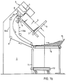
- the punching device has (FIG. 1a) in a housing 1 inclined guide rail 2, along which a first Stacking support 3 is displaceable. She's wearing one Storage stack 4 of congruent one on top of the other Scroll, which laterally from the guide rail 2 is supported.
- a pushing device 5 is arranged on one side and on the opposite side a punching device 6, the Distance from the pusher 5 is adjustable with several arranged in a row, movable up and down Stamp 7 as a processing tool.
- a trigger device 8 is located above the pushing device 5 attached to which a transport device 9 immediately connects. It includes two closed, over a transport route which has an arc of approximately 180 ° describes, parallel pairs of belts 10a, b.
- the Belt pair 10a runs along the transport route over a convex curved guide, e.g. B. made of aluminum sheet.
- a convex curved guide e.g. B. made of aluminum sheet.
- Below at the end of the transport route is another vertical one Guide rail 11 arranged, along which another Stack support 12 for receiving a target stack 13 vertically is movable.
- the stacking pad 12 is with wheels Mistake.
- the stack support 3 is increased by the thickness of one editing bundle shifted up, then the top one Bundle of the supply stack 4 by means of the pusher 5 offset in such a way that its edge area to be machined in the punching device 6 lies, the same punched and the Bundle gripped by the trigger device 8 and by the Transport device 9 fed to the target stack 13, wherein it is turned to maintain the sheet sequence.
- the described design of the transport device 9 allowed the transport of relatively stiff leaves, because the Transport route has a large radius of curvature, such as he with conventional drum-based ones Transport equipment only with incomparably higher Space could be achieved. Consecutive Bundles are processed and transported overlapping.
- the Stacking support 12 is lowered in such a way that the upper one End of the target stack 13 always just below the level of Exit of the transport device 9 remains. As soon as the Stacking surface 12 reaches the ground, holds the Punching device. The stack pad 12 can then on the Lowered floor, released and with the target stack 13 to be rolled away.
- the Push device 5 a slide 16 which is transverse to Storage stack 4 such that it in the end position on the Stacking pad 3 protrudes, can be pushed forward and retracted is. At the front end it has a concave butt surface 17 Mistake. It is made up of two from the top and bottom slightly inward sloping stripes formed one Include obtuse angle. Furthermore, the Push device 5 a pre-gripper 18 with a interchangeable beak 19 for engagement in the Storage stack 4, which feeds like the slider 16 and is retractable. The beak 19 indicates according to FIG. 2 a cutting edge 20 at its front end.
- This Training is suitable for editing sheets relatively thin material like paper, because the Cutting edge 20 then easily between two sheets lying on top of each other can penetrate.
- the pre-gripper 18 is in a holder 21 which on the Bottom of the slider 16 is attached in The feed direction can be moved to a limited extent.
- the Bracket 21 includes a parallel to the slider 16 Base plate 22, which has a front wall 23 at the front edge bears with a central, from its upper edge incised recess 24 through which the pre-gripper 18 protrudes, and further behind an intermediate wall 25, which they connects to the slide 16 and a bushing 26 having.
- a final double rear wall 27 forms a groove 28 oriented perpendicular to the feed direction, in which engages a driver roller 29 of a crank 30.
- the laterally open bracket 21 is on two Feed direction parallel support rods 31a, b slidable hung up. Through the space between the partition 25 and the rear wall 27 protrudes on the support rods 31a, b attached beam 32 with one from its upper edge incised slot 33.
- the pre-gripper 18 has (see also FIG. 2a) Pre-gripper housing 34, on the front of which the beak 19 on a centrally projecting projection is screwed on. Through the pre-gripper housing 34 runs in Feed direction a bore 35 which is a distance Surrounds bolt 36 which is rotatable at its foremost portion and is immovably mounted in the pre-gripper housing 34. Its front end is from the front of the pre-gripper 18 accessible and with a slot for engaging one Screwdriver. The protruding through the bore 35 Section of the bolt 36 carries a thread with a Adjusting nut 37 engages.
- a spiral spring surrounding the bolt 36 41 arranged.
- the adjusting nut 37 forms a first one Spring support for the spiral spring 41 and the intermediate wall 25 via the support ring 40 resting on its front side a second.
- a stop ring 42 is immovable on the bolt 36 attached to the back of the partition 25 a Driver stop forms.
- the Bolt 36 At its rear end is the Bolt 36 in turn is threaded and carries a stop nut 43 behind the bar 32.
- the spiral spring 41 which, as mentioned, on the support ring 40 is supported on the intermediate wall 25 of the holder 21, exercises a via the adjusting nut 37 on the pre-gripper 18 Force acting from the feed direction.
- the pre-gripper 18 is therefore in the retracted position shown in FIG. 2 of the slider 16 advanced so far relative to the same, as the driver ring 42 allows. Pushes the pre-gripper 18 when feeding on a test resistor, so it is against the bracket 21 against the force of the coil spring 41 retractable.
- the spring force is adjustable because the Adjusting nut 37 by rotating the bolt 36 by means of a at the front end attached screwdriver in Feed direction can be shifted. Shift of Setting nut 37 forward relaxes the spiral spring 41 and reduces the spring force, displacement to the rear reinforces it.
- the stop nut 43 forms with the back of the bar 32 a pre-gripper stop, which advances the Claw 18 limited.
- the pre-gripper housing 34 now has on its underside Profile 44 running essentially in the feed direction on with a first parallel to the feed direction Profile section 45 and further ahead a similar, but are somewhat higher with respect to the slider 16 second profile section 46, which by a down pointing prongs 47 are separated.
- the profile 44 is by one attached to the underside of the slider 16 Pressure spring 48, which is designed as a leaf spring and sliding against the top of the pre-gripper housing 34 presses to one at the bottom of the recess 24 in the Front wall 23 of the pre-gripper housing 34 arranged after nose 49 pressed above.
- the nose 49 can be from one abrasion-resistant screwed to the front wall 23 Exchange part are formed and z. B. made of brass consist.
- the force of the pressure spring 48 is by means of a Adjustable screw 50 adjustable.
- the interaction between the profile 44 and the nose 49 regulates the height position of the Gripper 18 against the slider 16 during the last Section of the feed of the latter.
- the pre-gripper 18 is so guided in the bracket 21 that he, after he was advanced in parallel with the slide 16, at the end its feed motion is raised and then back to one Position is lowered, which is at least that before lifting taken corresponds and is preferably somewhat deeper.
- the trigger device 8 has two (see also FIG. 3) Clamping elements, which act as disc segments 51a, b are trained. You are at a common driven shaft 52 attached. The partially cylindrical outer sections of the disk segments 51a, b form a Clamping surface 53, which is on one side of a lifting edge 54 is limited. The disc segments are on the inside 51a, b then slightly raised to the lifting edge 54. The The clamping surface 53 acts as a clamping roller 55 trained counter element together, which above the Disc segments 51a, b parallel to shaft 52 in one pivotable bracket 56 is rotatably mounted.
- the Bracket 56 is by means of a spiral spring 57 with a applied elastic force, which by means of a Knurled nut 58 is adjustable and the pinch roller 55 against the disc segments 51a, b presses.
- a Switch 59 provided the when the distance between the Pinch roller 55 and the clamping elements 51a, b a limit reached, actuated by the holder 56 and the Punching device stops. This can cause glitches of paper transport such as B. paper jams in the Transport device 9 can be avoided.
- the limit of the Switch 59 can be adjustable.
- the shaft 52 further carries lifting elements 60a, b, which essentially corresponding to the disk segments 51a, b trained, but opposite them by about 90 ° the direction of rotation of the shaft 52 are offset so that their Lifting edges 54 those of the disc segments 51a, b run after.
- the transport device 9 has in the area of Trigger device 8 two driven on a common Shaft 61 attached rollers 62a, b, over each of which flat conveyor belts 63a, b run which are the first Belt pair 10a (Fig. 1a, b) also form two more another driven shaft 64 attached rollers 65a, b, via which transport belts 66a, b round cross-section are guided, which form the second pair of belts 10b.
- Below the rollers 65a, b are two guide rollers 67a, b a spring-mounted shaft 68 is provided.
- the bracket 21 together with the slide 16 by turning the crank 30 advanced the pre-gripper 18 is taken along and with the cutting edge of his beak 19 in the Stack of sticks 4 and so a bundle 69 of one Remaining stack 70 separates.
- the puncture is spring-loaded Guiding the pre-gripper 18 in the holder 21 somewhat subdued.
- the stop nut 43 reaches the beam 32.
- the pre-gripper stop takes effect and prevents the pre-gripper 18 as the slide 16 is advanced is taken along (Fig. 4a).
- the nose 49 therefore slides on the first one Section 45 of the profile 44 at the bottom of the Vorackerergeophuses 34 and finally comes up against the Prongs 47, which means that the pre-gripper 18 is raised quickly causes.
- it lifts that of the pusher 5 facing edge region of the bundle 69 of leaves on top of the supply stack 4 slightly so that the edge the same - hereinafter called the opposite edge 71 - from the Butt surface 17 of the slider 16, which over the Storage stack 4 is advanced and at that moment Pre-gripper 18 catches up, is detected (Fig. 4b).
- the suspension of the pre-gripper 18 is by means of the adjusting nut 37 is set relatively soft, such that the end face 20 'when it is laterally connected to the Stack of 4 pushes, does not penetrate, but is pressed becomes, so that when the pre-gripper 18 is raised, the opposing edge a bundle is also lifted by friction.
- the nose 49 becomes over the prongs 47 pushed out so that the pre-gripper 18 from the Pressure spring 48 is pressed down again and one takes a slightly lower position than before lifting. It lies with the underside of the beak 19 on the top sheet of the remaining stack 70 and clamps the same firmly so that no sheets of the remaining stack 70 are pulled along be when the bundle 69 by further feeding the Slider 16 is offset so that its to machining edge area 72 into the punching device 6 lies while the remaining part of the bundle 69 predominantly rests on the remaining stack 70 (FIG. 4c).
- the stamp While the stamps 7 are withdrawn, the stamp is sent to the Opposing edge 71 adjoining area of the processed bundle 69 raised from the lifting edge 54 to the pinch roller 55 and between the same and that on the lifting edge 54 subsequent clamping surface 53 of the disc segments 51a, b clamped and thus pulled the bundle 69 and against the Direction of displacement of the transport device 9 supplied (Fig. 4e).
- the corner areas of the bundle 69 become something later than the center of the opposite edge 71 of the Lifting elements 60a, b (Fig. 2) detected, which thus the lifting of bundle 69 support.
- the slide 16 By further turning the Crank 30, the slide 16 has been withdrawn, whereby as soon as the intermediate wall 25 the stop ring 42 reached, the driver stop effective and the pre-gripper 18 was pulled.
- the supply stack becomes (FIG. 4f) 4 by means of the stack support 3 (Fig. 1a, b) Bundle thickness lifted and another bundle 69 'through the again advanced pre-gripper 18 in the area of Counter edge 71 raised and by the abutment surface 17 of the Slider 16 moved so that its to be machined Edge region 72 protrudes into the punching device 6, which means that Bundle 69 'corresponds to that of bundle 69 in FIG. 4c Has reached position.
- the bundles 69 become Maintaining the sheet order turned.
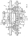
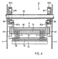
- the punching device 6 comprises (FIGS. 5a, b, 6) a carrier 73, in which the stamp 7 are held.
- a guide 74 and a die 75 which has a gap 76 between them Recording of the edge areas 72 to be processed by bundles 69 form, have holes 77 and 78 for receiving the stamp 7 on.
- the Gap 76 limited by an adjustable stop. He is by fingers of a sliding adjustment bar 79th formed, which protrude into the gap 76.
- the carrier 73 is with a bracket 80 screwed, which in a sliding guide 81 is slidably mounted transversely to the gap 76.
- One is intermittent for driving the punching device 6 rotating shaft 82 provided which two drive parts carries, which are designed as egg-shaped drive disks 83a, b are and each on the other drive pulley facing inside a closed drive groove 84th wear which the shaft 82, the edge line of the respective Following the drive pulley surrounds at an alternating distance.
- the drive grooves 84 engage parallel to the shaft 82 Tabs 85a, b protruding from the top of the bracket 80 Roll 86.
- the Thrust device 5 takes the one shown in FIG. 2 retracted position - will be after in the im Connection with the Fig. 4a-c described the Edge region 72 of a bundle 69 of those to be processed Scroll was pushed into the gap 76, the shaft 82 rotated and the rollers 86 each by the cam-like Bulge of the inner wall of the drive groove 84 downwards pressed. This draws a corresponding movement of the Bracket 80, the carrier 73 and the stamp 7 itself, so that the latter the edge region 72 lying in the gap 76 of the bundle 69 pierced and its lower limit position reach (Fig. 5b).
- the same type of drive can of course also be used in Embossing devices are used, which, at all apart from the different design of the stamp 7, can be constructed practically exactly the same, as in Relation to methods and devices, in particular for punching or embossing, in which the processing sequence or moving and transporting the bundles in another way is solved as shown above.
Description
- Fig. 1a
- eine schematische Seitenansicht einer erfindungsgemässen Stanzvorrichtung,
- Fig. 1b
- eine Seitenansicht enstprechend Fig. 1a, wobei die Stanzeinrichtung für die Bearbeitung von Blättern kleinen Formats umgestellt und modifiziert ist,
- Fig. 2
- vergrössert einen Längsschnitt durch einen Teil der Stanzvorrichtung von Fig. 1a, 1b,
- Fig. 2a
- in Seitenansicht eine abweichende Ausführungsform eines Bestandteils des Teils der Stanzvorrichtung gemäss Fig. 2,
- Fig. 3
- in Vorderansicht entsprechend Pfeil III den Teil der Stanzvorrichtung gemäss Fig. 2,
- Fig. 4a
- schematisch und z. T. vereinfacht den Teil der Stanzvorrichtung gemäss Fig. 2, 3 während eines ersten Stadiums der Durchführung des erfindungsgemässen Verfahrens mittels der besagten Vorrichtung,
- Fig. 4b
- in Fig. 4a entsprechender Darstellung ein zweites Stadium der Durchführung des erfindungsgemässen Verfahrens,
- Fig. 4c
- ein drittes Stadium der Durchführung des erfindungsgemässen Verfahrens,
- Fig. 4d
- ein viertes Stadium der Durchführung des erfindungsgemässen Verfahrens,
- Fig. 4e
- ein fünftes Stadium der Durchführung des erfindungsgemässen Verfahrens,
- Fig. 4f
- ein sechstes Stadium der Durchführung des erfindungsgemässen Verfahrens,
- Fig. 5a
- einen Längsschnitt durch einen weiteren Teil der erfindungsgemässen Stanzvorrichtung im ersten Stadium der Durchführung des erfindungsgemässen Verfahrens gemäss Fig. 4a,
- Fig. 5b
- in Fig. 5a entsprechender Darstellung das vierte Stadium des erfindungsgemässen Verfahrens gemäss Fig. 4d und
- Fig. 6
- einen Querschnitt längs VI-VI in Fig. 5a.
Claims (30)
- Verfahren zur bündelweisen Bearbeitung von deckungsgleichen Blättern eines flächigen Materials an einem Randbereich (72), wobei fortzu Bündel (69, 69') von Blättern aus einem Vorratsstapel (4) gegenüber einem verbleibenden Reststapel (70) versetzt werden, so dass jeweils der zu bearbeitende Randbereich (72) des Bündels (69) vom Reststapel (70) frei ist, die Bearbeitung vorgenommen und anschliessend das Bündel (69) im wesentlichen entgegen der Versetzungsrichtung zurückgezogen wird, dadurch gekennzeichnet, dass die Versetzung des Bündels (69) jeweils so bemessen ist, dass der gegenüber dem Randbereich (72) verbleibende Bereich desselben während der Bearbeitung des ersteren mit dem Reststapel (70) oder einem unmittelbar folgenden Bündel mindestens teilweise überlappt.
- Verfahren nach Anspruch 1, dadurch gekennzeichnet, dass ein Bündel (69) jeweils über eine Transportstrecke transportiert und dabei gewendet wird, wobei aufeinanderfolgende Bündel (69, 69') überlappen.
- Verfahren nach Anspruch 1 oder 2, dadurch gekennzeichnet, dass der Randbereich (72) des Bündels (69) jeweils nach der Versetzung desselben gegenüber dem Reststapel (70) unmittelbar bearbeitet wird und gegebenenfalls der Transport des Bündels (69) nach der Bearbeitung erfolgt.
- Verfahren nach Anspruch 3, dadurch gekennzeichnet, dass das Bündel (69) jeweils vom oberen Ende des Vorratsstapels (4) stammt und während der Bearbeitung des Randbereichs (72) mindestens mit einem Teil des verbleibenden Bereichs auf dem Reststapel (70) aufliegt.
- Verfahren nach einem der Ansprüche 1 bis 4, dadurch gekennzeichnet, dass die Versetzung eines Bündels (69) jeweils erfolgt, indem es durch seitliche Einwirkung auf den dem zu bearbeiteten Randbereich (72) gegenüberliegenden Gegenrand (71) gegenüber dem Reststapel (70) verschoben wird.
- Verfahren nach Anspruch 5, dadurch gekennzeichnet, dass der an den Gegenrand (71) eines Bündels (69) anschliessende Bereich jeweils vor der Verschiebung des Bündels (69) angehoben wird.
- Verfahren nach Anspruch 6, dadurch gekennzeichnet, dass mindestens das oberste Blatt des Reststapels (70) während der Verschiebung des Bündels (69) festgeklemmt wird.
- Verfahren nach einem der Ansprüche 1 bis 7, dadurch gekennzeichnet, dass ein Bündel (69) nach der Bearbeitung jeweils in Fortsetzung des Rückzugs von der Bearbeitung aus dem Bearbeitungsbereich abgezogen wird, wobei aufeinanderfolgende Bündel (69, 69') überlappen.
- Verfahren nach einem der Ansprüche 1 bis 8, dadurch gekennzeichnet, dass der an den Gegenrand (71) anschliessende Bereich des Bündels (69) zwischen einem Klemmelement und einem Gegenelement geklemmt und der Rückzug des Bündels (69) nach der Bearbeitung durch aktive Drehung mindestens eines der Elemente erfolgt.
- Vorrichtung zur Durchführung des Verfahrens nach einem der Ansprüche 1 bis 9, mit einer vertikal verschiebbaren Stapelauflage (3) zur Aufnahme eines Vorratsstapels (4) von Blättern, einer neben der Stapelauflage (3) angeordneten Versetzungseinrichtung zur Versetzung der Bündel (69) mit mindestens einem quer über die Stapelauflage (3) vorschiebbaren und zurückziehbaren Versetzungswerkzeug sowie einer Bearbeitungseinrichtung, dadurch gekennzeichnet, dass die Bearbeitungseinrichtung gleichfalls neben der Stapelauflage (3) angebracht ist.
- Vorrichtung nach Anspruch 10, dadurch gekennzeichnet, dass die Versetzungseinrichtung als auf der der Bearbeitungseinrichtung gegenüberliegenden Seite der Stapelauflage (3) angeordnete Schubeinrichtung (5) ausgebildet ist und das Versetzungswerkzeug als Schieber (16) mit an seinem der Stapelauflage (3) zugewandten Ende einer annähernd vertikalen Stossfläche (17).
- Vorrichtung nach Anspruch 11, dadurch gekennzeichnet, dass die Schubeinrichtung (5) einen unterhalb des Schiebers (16) quer über die Stapelauflage (3) vorschiebbaren und zurückziehbaren Vorgreifer (18) aufweist mit vorne einem Schnabel (19, 19') zur Trennung eines Bündels (69) vom Reststapel (70).
- Vorrichtung nach Anspruch 12, dadurch gekennzeichnet, dass der Vorgreifer (18) gegenüber dem Schieber (16) in Vorschubrichtung begrenzt verschiebbar gelagert und durch ein mittelbar oder unmittelbar am Schieber (16) abgestützes Federelement mit einer nach vorn gerichteten Kraft beaufschlagt ist und dass ein
- Vorrichtung nach Anspruch 13, dadurch gekennzeichnet, dass das Federelement zwischen einer ersten Federabstützung am Vorgreifer (18) und einer mit dem Schieber (16) verbundenen zweiten Federabstützung eingespannt ist, von denen mindestens eine zur Regelung der Federkraft verschiebbar ist.
- Vorrichtung nach Anspruch 14, dadurch gekennzeichnet, dass die erste Federabstützung als unverdrehbar gelagerte Einstellmutter (37) ausgebildet ist, die mit einem drehbar gelagerten, sich im wesentlichen in Vorschubrichtung erstreckenden Bolzen (36) des Vorgreifers (18) eingreift.
- Vorrichtung nach einem der Ansprüche 13 bis 15, dadurch gekennzeichnet, dass der Vorgreifer (18) über ein Profil (44) und eine Nase (49), welche aufgrund der nach dem Wirksamwerden des Vorgreiferanschlags einsetzende Relativbewegung zwischen dem Vorgreifer (18) und dem Schieber (16) am Profil (44) entlanggleitet, mit dem Schieber (16) wechselwirkt.
- Vorrichtung nach Anspruch 16, dadurch gekennzeichnet, dass zwischen dem Schieber (16) und dem Vorgreifer (18) eine Andrückfeder (48) wirksam ist, welche die Nase (49) und das Profil (44) gegeneinanderdrückt.
- Vorrichtung nach Anspruch 16 oder 17, dadurch gekennzeichnet, dass das Profil (44) an der Unterseite des Vorgreifers (18) und die Nase (49) nach oben vorspringend an einer mit dem Schieber (16) starr verbundenen Halterung (21) angeordnet ist.
- Vorrichtung nach Anspruch 18, dadurch gekennzeichnet, dass das Profil (44) in Vorschubrichtung aufeinanderfolgend einen zur Vorschubrichtung mindestens annähernd parallelen ersten Profilabschnitt (45) aufweist und einen mindestens auf gleicher Höhe, vorzugsweise etwas höher angeordneten ebensolchen zweiten Profilabschnitt (46) sowie zwischen denselben einen nach unten weisenden Zacken (47).
- Vorrichtung nach einem der Ansprüche 10 bis 19, mit einer Abzugseinrichtung (8) zum Abziehen von Bündeln (69) aus dem Bearbeitungsbereich, dadurch gekennzeichnet, dass die Abzugseinrichtung (8) mindestens ein um eine horizontale, zur Versetzungsrichtung mindestens annähernd normale Drehachse rotierendes Klemmelement aufweist, welches eine Hebekante (54) aufweist zum Untergreifen und Anheben des an den Gegenrand (71) eines Bündels (69) anschliessenden Bereichs und eine an die Hebekante (54) anschliessende, teilzylindrisch ausgebildete Klemmfläche (53), sowie mindestens ein oberhalb des Klemmelements angeordnetes Gegenelement, an welches das angehobene Bündel (69) durch die Klemmfläche (53) andrückbar ist.
- Vorrichtung nach Anspruch 20, dadurch gekennzeichnet, dass das mindestens eine Klemmelement im wesentlichen die Form eines Zylindersegments aufweist.
- Vorrichtung nach Anspruch 20 oder 21, dadurch gekennzeichnet, dass sie mindestens zwei an einer gemeinsamen angetriebenen Welle (52) befestigte Klemmelemente aufweist.
- Vorrichtung nach den Ansprüchen 21 und 22, dadurch gekennzeichnet, dass die Klemmelemente als Scheibensegmente (51a, 51b) ausgebildet sind.
- Vorrichtung nach einem der Ansprüche 20 bis 23, dadurch gekennzeichnet, dass das mindestens eine Gegenelement als Klemmwalze (55) ausgebildet ist.
- Vorrichtung nach einem der Ansprüche 20 bis 24, dadurch gekennzeichnet, dass das Gegenelement mit einem Schalter (59) verbunden ist, welcher anspricht, wenn der Abstand des Gegenelements von dem mindestens einen Klemmelement einen Grenzwert überschreitet.
- Vorrichtung nach einem der Ansprüche 20 bis 25, mit einer an die Abzugseinrichtung (8) anschliessenden Transporteinrichtung (9) zum Transportieren von Bündeln (69) über eine Transportstrecke, dadurch gekennzeichnet, dass die Transporteinrichtung (9) mindestens zwei Riemen aufweist, welche parallel geführt sind und die Bündel (69) zwischen sich klemmen.
- Vorrichtung nach Anspruch 26, dadurch gekennzeichnet, dass die Transportstrecke zum Wenden der Bündel (69) einen Bogen von ca. 180°beschreibt.
- Vorrichtung nach einem der Ansprüche 10 bis 27, dadurch gekennzeichnet, dass die Bearbeitungseinrichtung ein verschiebbares Bearbeitungswerkzeug umfasst, das mit einer antreibbaren Welle (82) derart formschlüssig verbunden ist, dass eine Umdrehung derselben eine auf- und abgehende Bewegung des Bearbeitungswerkzeugs erzwingt.
- Vorrichtung nach Anspruch 28, dadurch gekennzeichnet, dass die Welle (82) ein Antriebsteil trägt mit einer die Welle mit wechselndem Abstand umgebenden geschlossenen Nut (84), in welche ein mit dem Bearbeitungswerkzeug verbundener Finger parallel zur Welle (82) eingreift.
- Vorrichtung nach einem der Ansprüche 10 bis 29, dadurch gekennzeichnet, dass die Bearbeitungseinrichtung eine Stanzeinrichtung (6) oder eine Prägeeinrichtung ist.
Applications Claiming Priority (4)
| Application Number | Priority Date | Filing Date | Title |
|---|---|---|---|
| CH15495 | 1995-01-20 | ||
| CH15495 | 1995-01-20 | ||
| CH154/95 | 1995-01-20 | ||
| PCT/CH1996/000018 WO1996022243A1 (de) | 1995-01-20 | 1996-01-16 | Verfahren und vorrichtung zur bündelweisen bearbeitung von deckungsgleichen blättern eines flächigen materials |
Publications (2)
| Publication Number | Publication Date |
|---|---|
| EP0751905A1 EP0751905A1 (de) | 1997-01-08 |
| EP0751905B1 true EP0751905B1 (de) | 1999-12-22 |
Family
ID=4180485
Family Applications (1)
| Application Number | Title | Priority Date | Filing Date |
|---|---|---|---|
| EP96900232A Expired - Lifetime EP0751905B1 (de) | 1995-01-20 | 1996-01-16 | Verfahren und vorrichtung zur bündelweisen bearbeitung von deckungsgleichen blättern eines flächigen materials |
Country Status (7)
| Country | Link |
|---|---|
| US (1) | US5730437A (de) |
| EP (1) | EP0751905B1 (de) |
| JP (1) | JPH09510683A (de) |
| KR (1) | KR100433886B1 (de) |
| AT (1) | ATE187950T1 (de) |
| DE (1) | DE59603958D1 (de) |
| WO (1) | WO1996022243A1 (de) |
Families Citing this family (4)
| Publication number | Priority date | Publication date | Assignee | Title |
|---|---|---|---|---|
| US8276734B2 (en) * | 2001-03-21 | 2012-10-02 | Japan Cash Machine, Co., Ltd. | Bill validator with centering device |
| JP2009050981A (ja) * | 2007-08-28 | 2009-03-12 | Kataoka Mach Co Ltd | 傷痕加工装置 |
| JP5276457B2 (ja) * | 2009-01-23 | 2013-08-28 | 住友ゴム工業株式会社 | スペーサー供給装置、ビードの自動アッセンブル装置及びビードの自動アッセンブル方法 |
| CN115781801B (zh) * | 2023-02-03 | 2023-04-18 | 山西建投建筑产业有限公司 | 一种板材开槽机用自动化上料装置 |
Family Cites Families (5)
| Publication number | Priority date | Publication date | Assignee | Title |
|---|---|---|---|---|
| US3635463A (en) * | 1970-05-08 | 1972-01-18 | Stobb Inc | Sheet feeder off a stack of sheets |
| US3729190A (en) * | 1971-04-14 | 1973-04-24 | Warner Swasey Co | Rotating arm sheet unloader-stacker |
| DE2447601A1 (de) * | 1974-10-05 | 1976-04-08 | Eizo Sase | Papierbeschickungsvorrichtung fuer eine automatische stanzmaschine fuer ebenes papier |
| NL9002246A (nl) * | 1990-08-28 | 1992-03-16 | Ferag Ag | Werkwijze voor het verwerken van in een schubbenformatie beschikbaar komend drukwerk. |
| BE1008208A4 (nl) * | 1991-03-26 | 1996-02-13 | Gaspar A H Byttebier | Werkwijze en inrichting voor het verhandelen van vellen. |
-
1996
- 1996-01-16 WO PCT/CH1996/000018 patent/WO1996022243A1/de active IP Right Grant
- 1996-01-16 US US08/716,379 patent/US5730437A/en not_active Expired - Fee Related
- 1996-01-16 DE DE59603958T patent/DE59603958D1/de not_active Expired - Fee Related
- 1996-01-16 KR KR1019960705123A patent/KR100433886B1/ko not_active IP Right Cessation
- 1996-01-16 EP EP96900232A patent/EP0751905B1/de not_active Expired - Lifetime
- 1996-01-16 AT AT96900232T patent/ATE187950T1/de not_active IP Right Cessation
- 1996-01-16 JP JP8521943A patent/JPH09510683A/ja active Pending
Also Published As
| Publication number | Publication date |
|---|---|
| KR970701667A (ko) | 1997-04-12 |
| ATE187950T1 (de) | 2000-01-15 |
| WO1996022243A1 (de) | 1996-07-25 |
| DE59603958D1 (de) | 2000-01-27 |
| EP0751905A1 (de) | 1997-01-08 |
| KR100433886B1 (ko) | 2004-09-04 |
| US5730437A (en) | 1998-03-24 |
| JPH09510683A (ja) | 1997-10-28 |
Similar Documents
| Publication | Publication Date | Title |
|---|---|---|
| EP0056874B1 (de) | Vorrichtung zum Schneiden von Papier, Pappe oder dgl | |
| DE3816774A1 (de) | Verfahren und vorrichtung zum aufrollen einer bahn | |
| EP0476718B1 (de) | Vorrichtung zum Drahtheften von mehrteiligen Druckereierzeugnissen | |
| DE2639676C2 (de) | Vorrichtung zum Beschicken eines Rundstapelbogenanlegers | |
| DE2531072B2 (de) | Verfahren und Einrichtung zum Transport und zur Verarbeitung von Bogen in einer Stanztiegelpresse o.dgl | |
| DE1906939A1 (de) | Verfahren und Vorrichtung zum Herstellen einer Stossverbindung zwischen den Enden zweier Kartonbahnen | |
| DE2254262C2 (de) | Vorrichtung zum Anbringen von Beschlägen auf Werkstücken | |
| CH645294A5 (de) | Buchblockschneidmaschine. | |
| DE1277140B (de) | Vorrichtung zum Stapeln und Transportieren von flachen Gegenstaenden, insbesondere Papiertuechern | |
| EP0453935A1 (de) | Verfahren und Vorrichtung zum Überführen von gestapeltem, blattförmigem Gut von einem Ausgangsfeld zu einem Eingangsfeld einer Schneidmaschine | |
| DE2116734A1 (de) | Maschine zum Heften einer laufenden Stoffbahn | |
| DE1902794A1 (de) | Verfahren und Vorrichtung zum Beschicken von Kartonbearbeitungsmaschinen | |
| EP0751905B1 (de) | Verfahren und vorrichtung zur bündelweisen bearbeitung von deckungsgleichen blättern eines flächigen materials | |
| CH694504A5 (de) | Verfahren zum Schneiden von Blechtafeln zu Blechstreifen sowie Schneidevorrichtung zu dessen Durchfuehrung. | |
| DE3141075C2 (de) | Zuführeinrichtung für Blechstreifenstapel zur Zufuhr zu einem Stanzautomaten | |
| DE1302083B (de) | Vorrichtung zum UEberfuehren von Blattsaetzen von einem Blattstapel an eine Foerdereinrichtung | |
| EP2607092B1 (de) | Vorrichtung und Verfahren zur Herstellung von Tischkalendern | |
| DE3642260C2 (de) | Vorrichtung zum Positionieren eines Blattstapels auf dem Stanztisch einer Stanzmaschine | |
| DE1153234B (de) | Vorrichtung zur Herstellung von Faltschachteln | |
| DE3317084C2 (de) | ||
| EP0753386B1 (de) | Vorrichtung zum Beschneiden von gefalteten Druckereierzeugnissen, wie Zeitungen, Zeitschriften, Broschüren und dergleichen | |
| EP1584432A1 (de) | Stanze zum Konturenstanzen eines vorgeschnittenen Nutzenstapels | |
| DE2836480B2 (de) | Vorrichtung zum Aufnehmen und Drehen eines Bandbundes | |
| DE4422194C1 (de) | Schneidverfahren für gestapeltes, blättriges Gut | |
| DE2615152A1 (de) | Vorrichtung zum transportieren von blaettern |
Legal Events
| Date | Code | Title | Description |
|---|---|---|---|
| PUAI | Public reference made under article 153(3) epc to a published international application that has entered the european phase |
Free format text: ORIGINAL CODE: 0009012 |
|
| 17P | Request for examination filed |
Effective date: 19960918 |
|
| AK | Designated contracting states |
Kind code of ref document: A1 Designated state(s): AT BE CH DE DK ES FR GB IT LI NL SE |
|
| 17Q | First examination report despatched |
Effective date: 19971001 |
|
| GRAG | Despatch of communication of intention to grant |
Free format text: ORIGINAL CODE: EPIDOS AGRA |
|
| GRAG | Despatch of communication of intention to grant |
Free format text: ORIGINAL CODE: EPIDOS AGRA |
|
| GRAH | Despatch of communication of intention to grant a patent |
Free format text: ORIGINAL CODE: EPIDOS IGRA |
|
| GRAH | Despatch of communication of intention to grant a patent |
Free format text: ORIGINAL CODE: EPIDOS IGRA |
|
| GRAA | (expected) grant |
Free format text: ORIGINAL CODE: 0009210 |
|
| AK | Designated contracting states |
Kind code of ref document: B1 Designated state(s): AT BE CH DE DK ES FR GB IT LI NL SE |
|
| PG25 | Lapsed in a contracting state [announced via postgrant information from national office to epo] |
Ref country code: SE Free format text: THE PATENT HAS BEEN ANNULLED BY A DECISION OF A NATIONAL AUTHORITY Effective date: 19991222 Ref country code: NL Free format text: LAPSE BECAUSE OF FAILURE TO SUBMIT A TRANSLATION OF THE DESCRIPTION OR TO PAY THE FEE WITHIN THE PRESCRIBED TIME-LIMIT Effective date: 19991222 Ref country code: ES Free format text: THE PATENT HAS BEEN ANNULLED BY A DECISION OF A NATIONAL AUTHORITY Effective date: 19991222 |
|
| REF | Corresponds to: |
Ref document number: 187950 Country of ref document: AT Date of ref document: 20000115 Kind code of ref document: T |
|
| REG | Reference to a national code |
Ref country code: CH Ref legal event code: EP |
|
| PG25 | Lapsed in a contracting state [announced via postgrant information from national office to epo] |
Ref country code: AT Free format text: LAPSE BECAUSE OF NON-PAYMENT OF DUE FEES Effective date: 20000116 |
|
| REF | Corresponds to: |
Ref document number: 59603958 Country of ref document: DE Date of ref document: 20000127 |
|
| PG25 | Lapsed in a contracting state [announced via postgrant information from national office to epo] |
Ref country code: BE Free format text: LAPSE BECAUSE OF NON-PAYMENT OF DUE FEES Effective date: 20000131 |
|
| GBT | Gb: translation of ep patent filed (gb section 77(6)(a)/1977) |
Effective date: 20000128 |
|
| ET | Fr: translation filed | ||
| ITF | It: translation for a ep patent filed |
Owner name: ING. A. GIAMBROCONO & C. S.R.L. |
|
| REG | Reference to a national code |
Ref country code: CH Ref legal event code: NV Representative=s name: ZIMMERLI, WAGNER & PARTNER AG |
|
| PG25 | Lapsed in a contracting state [announced via postgrant information from national office to epo] |
Ref country code: DK Free format text: LAPSE BECAUSE OF FAILURE TO SUBMIT A TRANSLATION OF THE DESCRIPTION OR TO PAY THE FEE WITHIN THE PRESCRIBED TIME-LIMIT Effective date: 20000322 |
|
| NLV1 | Nl: lapsed or annulled due to failure to fulfill the requirements of art. 29p and 29m of the patents act | ||
| BERE | Be: lapsed |
Owner name: BOYADJIAN HRATCH Effective date: 20000131 |
|
| PLBE | No opposition filed within time limit |
Free format text: ORIGINAL CODE: 0009261 |
|
| STAA | Information on the status of an ep patent application or granted ep patent |
Free format text: STATUS: NO OPPOSITION FILED WITHIN TIME LIMIT |
|
| 26N | No opposition filed | ||
| REG | Reference to a national code |
Ref country code: GB Ref legal event code: IF02 |
|
| PGFP | Annual fee paid to national office [announced via postgrant information from national office to epo] |
Ref country code: IT Payment date: 20060131 Year of fee payment: 11 |
|
| PGFP | Annual fee paid to national office [announced via postgrant information from national office to epo] |
Ref country code: CH Payment date: 20080124 Year of fee payment: 13 |
|
| PGFP | Annual fee paid to national office [announced via postgrant information from national office to epo] |
Ref country code: GB Payment date: 20080116 Year of fee payment: 13 |
|
| PGFP | Annual fee paid to national office [announced via postgrant information from national office to epo] |
Ref country code: FR Payment date: 20080108 Year of fee payment: 13 |
|
| PGFP | Annual fee paid to national office [announced via postgrant information from national office to epo] |
Ref country code: DE Payment date: 20090108 Year of fee payment: 14 |
|
| REG | Reference to a national code |
Ref country code: CH Ref legal event code: PL |
|
| GBPC | Gb: european patent ceased through non-payment of renewal fee |
Effective date: 20090116 |
|
| PG25 | Lapsed in a contracting state [announced via postgrant information from national office to epo] |
Ref country code: IT Free format text: LAPSE BECAUSE OF NON-PAYMENT OF DUE FEES Effective date: 20070116 |
|
| PG25 | Lapsed in a contracting state [announced via postgrant information from national office to epo] |
Ref country code: LI Free format text: LAPSE BECAUSE OF NON-PAYMENT OF DUE FEES Effective date: 20090131 Ref country code: CH Free format text: LAPSE BECAUSE OF NON-PAYMENT OF DUE FEES Effective date: 20090131 |
|
| REG | Reference to a national code |
Ref country code: FR Ref legal event code: ST Effective date: 20091030 |
|
| PG25 | Lapsed in a contracting state [announced via postgrant information from national office to epo] |
Ref country code: GB Free format text: LAPSE BECAUSE OF NON-PAYMENT OF DUE FEES Effective date: 20090116 |
|
| PG25 | Lapsed in a contracting state [announced via postgrant information from national office to epo] |
Ref country code: FR Free format text: LAPSE BECAUSE OF NON-PAYMENT OF DUE FEES Effective date: 20090202 |
|
| PG25 | Lapsed in a contracting state [announced via postgrant information from national office to epo] |
Ref country code: DE Free format text: LAPSE BECAUSE OF NON-PAYMENT OF DUE FEES Effective date: 20100803 |