EP0734653B1 - Automatische Einrichtung zum geordneten Überführen von Fischen in eine Fischbearbeitungsmaschine - Google Patents
Automatische Einrichtung zum geordneten Überführen von Fischen in eine Fischbearbeitungsmaschine Download PDFInfo
- Publication number
- EP0734653B1 EP0734653B1 EP96102154A EP96102154A EP0734653B1 EP 0734653 B1 EP0734653 B1 EP 0734653B1 EP 96102154 A EP96102154 A EP 96102154A EP 96102154 A EP96102154 A EP 96102154A EP 0734653 B1 EP0734653 B1 EP 0734653B1
- Authority
- EP
- European Patent Office
- Prior art keywords
- fish
- turning
- processing machine
- channel
- conveyor
- Prior art date
- Legal status (The legal status is an assumption and is not a legal conclusion. Google has not performed a legal analysis and makes no representation as to the accuracy of the status listed.)
- Expired - Lifetime
Links
- 241000251468 Actinopterygii Species 0.000 title claims description 119
- 238000012545 processing Methods 0.000 claims description 21
- 230000011514 reflex Effects 0.000 claims description 11
- 238000012546 transfer Methods 0.000 claims description 7
- 230000004888 barrier function Effects 0.000 claims description 5
- 230000010355 oscillation Effects 0.000 claims description 4
- 210000001015 abdomen Anatomy 0.000 claims description 2
- 230000002093 peripheral effect Effects 0.000 claims description 2
- 238000007599 discharging Methods 0.000 claims 1
- 238000007788 roughening Methods 0.000 claims 1
- 210000003128 head Anatomy 0.000 description 7
- 238000000034 method Methods 0.000 description 6
- 230000008569 process Effects 0.000 description 5
- 230000007246 mechanism Effects 0.000 description 3
- 238000013461 design Methods 0.000 description 2
- 230000000694 effects Effects 0.000 description 2
- 238000009740 moulding (composite fabrication) Methods 0.000 description 2
- 229930014626 natural product Natural products 0.000 description 2
- 238000000926 separation method Methods 0.000 description 2
- 210000004894 snout Anatomy 0.000 description 2
- 230000009182 swimming Effects 0.000 description 2
- 108010076504 Protein Sorting Signals Proteins 0.000 description 1
- 241001022395 Semotilus corporalis Species 0.000 description 1
- 230000003187 abdominal effect Effects 0.000 description 1
- 230000001133 acceleration Effects 0.000 description 1
- 238000009825 accumulation Methods 0.000 description 1
- 230000009471 action Effects 0.000 description 1
- 230000003213 activating effect Effects 0.000 description 1
- 230000004913 activation Effects 0.000 description 1
- 230000015572 biosynthetic process Effects 0.000 description 1
- 238000004040 coloring Methods 0.000 description 1
- 238000001514 detection method Methods 0.000 description 1
- 238000005755 formation reaction Methods 0.000 description 1
- 230000000266 injurious effect Effects 0.000 description 1
- 238000003780 insertion Methods 0.000 description 1
- 230000037431 insertion Effects 0.000 description 1
- 238000002955 isolation Methods 0.000 description 1
- 238000010030 laminating Methods 0.000 description 1
- 238000005259 measurement Methods 0.000 description 1
- 238000005457 optimization Methods 0.000 description 1
- 230000000717 retained effect Effects 0.000 description 1
- 238000005096 rolling process Methods 0.000 description 1
- 239000002356 single layer Substances 0.000 description 1
- 230000007704 transition Effects 0.000 description 1
Images

Classifications
-
- A—HUMAN NECESSITIES
- A22—BUTCHERING; MEAT TREATMENT; PROCESSING POULTRY OR FISH
- A22C—PROCESSING MEAT, POULTRY, OR FISH
- A22C25/00—Processing fish ; Curing of fish; Stunning of fish by electric current; Investigating fish by optical means
- A22C25/08—Holding, guiding, or conveying fish before, during or after its preparation ; Devices for sizing fish; Automatically adapting conveyors or processing machines to the measured size
Definitions
- the invention relates to an automatic device for organizing and uniform alignment of fish for automatic insertion into and Processing the fish in a fish processing machine.
- Such automation i. H. unattended operation of such Facilities from the batch task to the entry in and Pass through the processing machine is due to the different properties of the natural product fish, such as B. size, Consistency, shape fidelity and a. as well as due to the Throughput performance very problematic.
- Such a device is known for example from GB 1090737.
- a method and a device for orienting and orderly transferring fish are described.
- a device provided for this purpose can also be found in EP 0116 782.
- the central element of this device which consists of a feed conveyor, a longitudinal judge and a belly-back judge, is an image acquisition system, which is arranged downstream of the longitudinal judge and provides image information that enables each fish to be positioned in an optimal position for the head.
- the image acquisition system simultaneously controls the alignment of each fish and controls the course influencing its conveying path, so that each fish is handled individually, ie ejected in the event of incorrect head-to-tail alignment and directed into a turning section in the case of incorrect abdominal-back alignment.
- an automatic device for the orderly transfer of fish into a Fish processing machine which comprises: a feed conveyor, Means for distributing and equalizing the fish from a fish mass, Means for dividing the fish lengthways with a turning device for Align the fish in a uniform head-tail position, Means for aligning the fish in a uniform abdominal-back position, Means for the individual removal and intermittent input of the fish into one Cross conveyor with chambers for the individual reception of the fish, sensor means for Check the abdominal-back position of each fish and means for turning missing fish in a uniform abdominal-back position, the Sensor means one arranged above the web of the cross conveyor Reflex sensors consist of a transmitter part and a receiver part.
- the straightening channel is designed so that the Fish are transferred to a partial lane of the same, in which then one further equalization takes place in that the fish as a result of the Oscillating movement of the straightening channel is moved in the swimming direction become.
- half of that of the straightening channel becomes allocated fish opposite to the working direction of the overall situation promoted, the turning device arranged in their path a Turning and at the same time assigning these fish to the other partial lane the straightening gutter causes the fish in two rectified Streams continue without mutual hindrance.
- abdominal-back alignment station In the following abdominal-back alignment station is used by every fish its cross-sectional geometry in the pass initially in a floating position straightened up and then uniform in terms of the location of his back Lateral position transfers in which orientation the fish is in the waiting position are held, from which they are called up individually and forwarded in cycles become.
- the appropriate means are preferably designed so that the fish despite the high clock rate, no hurtful experience what is achieved in that the detection of the fish in the waiting position at relatively low speed, which leads to the release of the fish is increased so that injurious acceleration forces are avoided become.
- Feed conveyor serving cross conveyor means for turning such Fish can be arranged if necessary by light-optical sensor means can be activated.
- the sensor means can preferably be used as reflex sensors be formed, the reflex signal with respect to its intensity profile is evaluated. Due to the darkening of the back and the The coloring of the belly of the fish is achieved by a minimum-maximum sequence signals an incorrect position, which is activated by activating the Turning means can be corrected.
- the turning lever controllable against the turning disc, so that on the misaligned Fish a turning moment is effective that this around its longitudinal axis turns by 180 °.
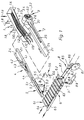
- the device for orderly Transferring fish to a fish processing machine does not shown, usually designed as an inclined conveyor Feed conveyor, a fish distributing and equalizing conveyor 1, a longitudinal straightening device 2 with a straightening channel 2.1 for the fish, a turning device 3 for aligning the fish in a uniform head-tail position, an alignment device 4 for aligning the fish in uniform abdominal-back position, a clock device 5 for Individual acceptance of the fish provided and their cyclical entry in a cross conveyor 6, measuring means 7 for checking the abdominal-back position each fish and a turning mechanism 8 for turning missing fish.
- the conveyor 1 consists of a Moving grate 1.1 with a conveying surface 1.2, which in the conveying direction of Fish-aligned and adjacent grate bars 1.3 is formed.
- the grate bars 1.3 are, as can be seen in FIG. 2, by yokes 1.4 and 1.5 connected so that the grate surface from two is formed comb-like partial grids. Every partial grate is via support arms 1.6 or 1.7 with a pair of synchronously rotating Crankshafts 1.8 connected, the support arms 1.6 and 1.7 of the two Partial gratings on cranks 1.9 and 1.10 offset by 180 ° attack.
- the conveying area 1.2 is increasing in the task area 1.11 and executed in a sloping manner in the delivery area, the conveying surface 1.2 ends above the straightening channel 2.1 of the longitudinal straightening device 2.
- the width of the Conveying surface 1.2 is coordinated with the width of the straightening channel 2.1, whereby the edge bars 1.12 and the center bar 1.13 are extended.
- the traveling grate 1.1 takes over on the inner edge rod 1.12 attached shoulder element 1.14 the Delimitation from the neighboring funding area.
- the edge bar 1.12 is at the bottom Guide surface 1.15 arranged above the longitudinal center of the straightening channel 2.1 ends.
- the straightening channel 2.1 of the longitudinal straightening device 2 has a U-shaped one Cross-section and is driven in a suitable manner longitudinally oscillating.
- the straightening channel 2.1 is in its task area with a support surface 2.4 provided in the middle in two part of the guide rail 2.5, the is extended beyond the rear end of the gutter 2.1 and in a separating wedge 2.6 ends.
- Under the end of the straightening channel 2.1 is one Slide 3.1 arranged, which is part of the turning device 3. According to FIGS. 1 and 3, this consists of one by one horizontal axis 3.2 rotating brush roller 3.3, on the underside of the slide 3.1 forms a tangent plane.
- the slide 3.1 merges into a guiding jacket 3.4, which defines the rear extent of the Brush roller 3.3 surrounds and beyond their culmination point in one to the support surface 2.4 of the straightening channel 2.1, the guide surface inclined forward 3.5 ends.
- the device 4 for aligning the fish in a uniform abdominal-back position is assigned to the straightening channel on the output side and consists of each other opposite guide surfaces 4.2 forming a guide channel 4.1, the entrance of the guide channel 4.1 with 4.3 formings for draining excess fish are provided.
- On the output side are Guides 4.2 twisted in the same direction, so that the Channel cross-section at the passage of the fish a turn around their Longitudinal axis causes.
- the guide channel 4.1 continues in a transfer channel 4.4, which is the Device 5 for individual takeover of the fish provided and their is passed on in cycles (FIG. 6).
- the device 5 includes a Guide channel 5.1 U-shaped cross section, the bottom surface through the Conveyor strand 5.2 of an endless conveyor belt 5.3 is formed.
- the Conveyor belt 5.3 is around a deflection roller 5.4 and a drive pulley 5.5 guided and on its conveying surface in a row next to each other arranged spikes 5.7, their division to the extent of Drive pulley is in an integer ratio.
- the Drive disc 5.5 is driven by an elliptical gear 5.6 and so coupled with it that the spines 5.7 at the moment of appearance and transition into the funding strand 5.2 a minimum speed and have a maximum speed at the moment of descent.
- a catch flap 5.8 is in the area above the point of appearance of the stinger 5.7 arranged around a fixed axis against a spring 5.9 in Running direction of the conveyor belt 5.3 is pivotable.
- the flap 5.8 is tunnel-shaped and has a vertical cross-section Provide level resilient pre-stoppers 5.10.
- the guide channel 5.1 of the clock device 5 ends above the cross conveyor 6.
- the trough conveyor for example a fish-head filleting machine identical and consists of a chain of Receiving troughs 6.1, which are arranged directly next to each other and serve the individual shot of the fish.
- the admission troughs 6.1 exist each from a body trough 6.2 and a head trough 6.3, the under Leaving a gap 6.4 are arranged between them.
- Stop rail 6.5 to catch the fish on their snout.
- the cross conveyor 6 guides the fish through the measuring means 7 (Fig. 7).
- Photoelectric barrier 7.5 forms.
- the transmitter part 7.2 is the receiver part 7.4 opposite, while the receiver part 7.3 points to an observation point is focused on the axis of the light barrier 7.5 at a distance an average fish thickness over the contact surface 6.6 of the fish in the Receiving troughs 6.1.
- the measuring means 7 are connected to the control unit via a control unit (not shown) Turning mechanism 8 connected (Fig. 8).
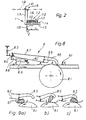
- a driven turning disc 8.1 which in the gap 6.4 is arranged between the body depressions 6.2 and the head depressions 6.3 and protrudes with its periphery by a small amount over the contact surface 6.6.
- the turning disc 8.1 is compared to the speed of the Cross conveyor 6 about twice the speed and running with it driven.
- the turning disc 8.1 is in the gap 6.4 protruding hold-down 8.2 opposite, as a towed Swivel lever trained and by the fish against a spring 8.3 is displaceable.
- the hold-down 8.2 is pivotable about an axis 8.4 fixed to the frame and carries a hook-shaped turning lever 8.5 in the area of its free end , which is articulated on the hold-down 8.2 and in its swivel plane is pivotally mounted.
- the turning lever 8.5 has one of the turning discs 8.1 facing concave catch surface 8.6, which over the contact surface 6.6 of the receiving troughs 6.1 towering part of the periphery of the Turntable 8.1 spanned.
- Intervenes on the pivot lever 8.5 Handlebar 8.7 on, which is connected to a crank 8.8, the crank axis corresponds to that 8.4 of the hold-down 8.2.
- the crank 8.8 is by means of of a pneumatic cylinder 8.9 can be swiveled.
- the dropping takes place through the guide surface 1.15 into one of the two by the guardrail 2.5 separate webs of the Straightening channel 2.1.
- the fish are keeping their longitudinal orientation in this Partial line advanced, each fish only in its swimming direction is promoted. Since the fish with both the head and the If the tail reaches the straightening channel 2.1, this means that the latter the straightening channel 2.1 are promoted.
- the one with the head advance fish pointing downwards in the straightening channel 2.1 the fish pointing downwards with the tail Head headed to the turning device 3, through the brush roller 3.3 recorded and the straightening channel 2.1 turned forward again.
- the The transfer takes place through the guide bridge 3.6 into the free sublane the straightening gutter 2.1, so that in this two without mutual Disability downward moving streams of fish formed from fish be the head ahead of the alignment device 4 for Unifying their abdominal-back position.
- the two fish streams are combined in the alignment device 4.
- Each fish is initially in using its cross-sectional geometry Floating position erected and then in a uniform side position brought. Too many fish brought in can go over the side Formations 4.3 derived from the fish stream and over one suitable conveyors are fed back into the process.
- the fish are first run through the flap 5.8 stopped, with its snout in the front End area comes to the plant. A possibly about the first fish pushing second fish is held back by the pre-stop 5.10.
- the first fish below is now moved through the conveyor belt 5.3 in the guide channel 5.1 raised spines 5.7 and moved forward.
- the catch flap 5.8 is taken along by the fish until it is caught is released. Due to the position of the pivot axis of the flap 5.8
- the pre-stop 5.10 hardly changes its altitude, so that a second fish held on during this process further retained becomes.
- the fish lying on it takes advanced by the delivery pressure of the straightening channel 2.1, the original position until the following spines appear 5.7 capture this fish. Capturing the fish through the spines 5.7 takes place at low speed, which is increased after access, so that comparatively low mass forces are effective on the fish.
- the transfer of the fish to the cross conveyor 6 takes place at one Maximum speed with timing of the timing with the Position of the receiving troughs 6.1.
- the turning lever is used for this 8.5 caused by activation of the pneumatic cylinder 8.9 in the web of the fish to be turned in (Fig. 8), this grasp and push against the turning disc 8.1. Due to the compared to the conveying speed of the cross conveyor 6 higher The peripheral speed of the turning disc 8.1 is the fish in one Rolling movement turned around its longitudinal axis.
- the drawing shows a single lane Feeder shown. To that of the downstream Providing the machine with the required loading capacity has become a reality a four-lane arrangement has proven itself in practice. The drawing shows further a sequence of functions that can be changed without this the idea of the invention is abandoned. So it is conceivable that the Alignment device 4 integrated into the effective range of the clock device 5 is.
Landscapes
- Life Sciences & Earth Sciences (AREA)
- Engineering & Computer Science (AREA)
- Wood Science & Technology (AREA)
- Zoology (AREA)
- Food Science & Technology (AREA)
- Processing Of Meat And Fish (AREA)
- Farming Of Fish And Shellfish (AREA)
- Attitude Control For Articles On Conveyors (AREA)
- Control Of Conveyors (AREA)
Description
Weiter ist eine dafür vorgesehene Einrichtung der EP 0116 782 zu entnehmen. Zentrales Element dieser aus Zubringerförderer, Längsrichter und Bauch-Rücken-Richter bestehenden Einrichtung ist ein Bilderfassungssystem, welches dem Längsrichter nachgeordnet ist und eine Bildinformation liefert, die eine Positionierung jedes Fisches in eine für das Köpfen optimale Lage ermöglicht. Zu diesem Zweck kontrolliert das Bilderfassungssystem gleichzeitig die Ausrichtung jedes Fisches und steuert dessen Förderweg beeinflussende Weichen, so daß jeder Fisch individuell gehandhabt, d. h. bei fehlerhafter Kopf-Schwanz-Ausrichtung ausgeworfen und bei fehlerhafter Bauch-Rücken-Ausrichtung in eine Wendestrecke geleitet wird.
- Fig. 1
- eine schematische Gesamtansicht einer einbahnigen Einrichtung in perspektivischer Ansicht mit aus Gründen der Übersichtlichkeit gegenüber der Längsrichteinrichtung überhöht dargestelltem Förderer,
- Fig. 2
- eine Querschnittansicht der Mittel zum Verteilen und Entzerren der Fische, lediglich einbahnig dargestellt,
- Fig. 3
- einen Längsschnitt durch die Mittel zum Längsrichten der Fische mit integrierter Kopf-Schwanz-Wendevorrichtung,
- Fig. 4
- eine Einzelheit der Wendevorrichtung nach Fig. 3;
- Fig. 5
- das Antriebsschema der Richtrinnen bei einer Vierbahn-Ausführung der Mittel zum Längsrichten, von unten betrachtet;
- Fig. 6
- eine schematische Seitenansicht der Mittel zur Vereinzelung,
- Fig. 7
- eine schematische Ansicht der Sensormittel,
- Fig. 8
- eine schematische Seitenansicht der Mittel zum Wenden bezüglich Bauch-Rücken-Lage fehlliegender Fische und
- Fig. 9
- eine Darstellung des Bauch-Rücken-Wendevorganges in a) bis c) einzelnen Phasen,
Claims (31)
- Automatische Einrichtung zum geordneten Überführen von Fischen in eine Fischbearbeitungsmachine umfassendeinen Zubringerförderer,Mittel (1) zum Verteilen und Entzerren der Fische aus einer Fischmasse,Mittel (2) zum Längsteilen der Fische mit einer Wendevorrichtung (3) zum Ausrichten der Fische in einheitliche Kopf-Schwanz-Lage,Mittel (4) zum Ausrichten der Fische in einheitliche Bauch-Rücken-Lage,Mittel (5) zur Einzelentnahme und taktweisen Eingabe der Fische in einen Querförderer (6) mit Kammern zur Einzelaufnahme der Fische,Sensormittel (7) zur Kontrolle der Bauch-Rücken-Lage jedes Fisches undMittel (8) zum Wenden fehlliegender Fische in einheitliche Bauch-Rücken-Lage, wobei die Sensormittel einen über der Bahn des Querförderers (6) angeordneten Reflextaster (7.1) aus einem Senderteil (7.2) und einem Empfängerteil (7.3) umfassen.
- Einrichtung nach Anspruch 1, dadurch gekennzeichnet, daß die Mittel (1 ) zum Verteilen und Entzerren einen Wanderrost (1.1) mit in Förderrichtung der Fische ausgerichteten Roststäben (1.3) umfaßt, wobei jeweils benachbarte Roststäbe (1.3) eine gegenphasige Hebe-Vorschub- bzw. Senk-Rückzug-Oszillationsbewegung ausführen.
- Einrichtung nach Anspruch 2, dadurch gekennzeichnet, daß die Förderfläche (1.2) des Wanderrostes (1.1) mindestens eine durch seitliche Schulterelemente (1.14) begrenzte Längskammer aufweist, deren Breite etwa der doppelten Breite des größten bestimmungsgemäß zu verarbeitenden Fisches entspricht, wobei sowohl die Randstäbe (1.12) als auch jeweils der zwischen diesen befindliche mittlere Roststab (1.13) über das ablaufseitige Ende der übrigen Roststäbe (1.3) hinaus verlängert sind.
- Einrichtung nach Anspruch 2 oder 3, dadurch gekennzeichnet, daß die Förderfläche (1.2) des Wanderrostes (1.1) mindestens bereichsweise in Förderrichtung ansteigend ausgeführt ist.
- Einrichtung nach einem der Ansprüche 1 bis 4, dadurch gekennzeichnet, daß die Mittel zum Längsrichten (2) mindestens eine in Längsrichtung oszillierend angetriebene Richtrinne (2.1) im wesentlichen U-förmigen Querschnitts aufweist, wobei die Breite ihrer Stützfläche (2.4) etwa der doppelten Breite des größten bestimmmungsgemäß zu verarbeitenden Fisches entspricht und wobei die Richtrinne (2.1) unterhalb des ablaufseitigen Endes der Förderfläche (1.2) des Wanderrostes (1.1) angeordnet ist.
- Einrichtung nach Anspruch 5, dadurch gekennzeichnet, daß die Richtrinne (2.1) mindestens im Bereich unterhalb der verlängerten Roststäbe (1.3) des Wanderrostes (1.1) mit einer die Richtrinne (2.1) längsmittig in zwei Teilbahnen trennenden Leitschiene (2.5) versehen ist.
- Einrichtung nach Anspruch 5 oder 6, dadurch gekennzeichnet, daß im Bereich der Verlängerung eines der Randstäbe (1.12) des Wanderrostes (1.1) und zwischen dieser und der Richtrinne (2.1) eine Leitfläche (1.15) zur Hinleitung der von dem Wanderrost (1.1) abgegebenen Fische in eine der Teilbahnen der Richtrinne (2.1) angeordnet ist.
- Einrichtung nach einem der Ansprüche 1 bis 7, dadurch gekennzeichnet, daß die Wendevorrichtung (3) eine angetriebene Bürstenwalze (3.3) umfaßt, welche im Bereich über dem hinteren Ende der Richtrinne (2.1) gelagert und von einem zu der Bürstenwalze (3.3) konzentrischen Leitmantel (3.4) umgeben ist, der die Bürstenwalze (3.3) im wesentlichen an ihrem rückwärtigen Umfang umgibt.
- Einrichtung nach Anspruch 8, dadurch gekennzeichnet, daß der Leitmantel (3.4) der Bürstenwalze (3.3) an seiner Innenseite mit einem schraubengangförmigen Leitsteg (3.6) versehen ist.
- Längsrichteinrichtung in einer automatischen Einrichtung zum geordneten Überführen von Fisch in einer Fischbearbeitungsmaschine nach einem oder mehreren der vorgenannten Ansprüche, mit zwei Paaren nebeneinander angeordneten Richtrinnen (2.1); dadurch gekennzeichnet, daß jeweils die äußeren zu den inneren Richtrinnen gegenphasig oszillierend angetrieben sind.
- Einrichtung nach Anspruch 10, dadurch gekennzeichnet, daß jeweils eine äußere Richtrinne (2.1) und die neben der anderen äußeren befindliche Richtrinne durch mindestens einen um eine vertikale Mittelachse (2.3) schwenkbaren zweiarmigen Lenker (2.2) miteinander verbunden sind.
- Einrichtung nach einem der Ansprüche 5 bis 11, dadurch gekennzeichnet, daß die Stützfläche (2.4) der Richtrinnen (2.1) aufgerauht ist.
- Einrichtung nach Anspruch 12, dadurch gekennzeichnet, daß die Aufrauhung durch Querschliff der Stützflächen (2.4) erzeugt ist.
- Einrichtung nach einem der Ansprüche 1 bis 13, dadurch gekennzeichnet, daß die Mittel (4) zum Ausrichten der Fische in einheitliche Bauch-Rücken-Lage je eine jeder Richtrinne (2.1) ausgangsseitig zugeordnete Ausrichtstation umfaßt, wobei jede einen Leitkanal (4.1) aus Leitflächen (4.2) aufweist, mit deren Hilfe jeder Fisch auf den Bauch stellbar und in bezüglich der Lage seines Rückens einheitliche Seitenlage überführbar ist.
- Einrichtung nach Anspruch 14, dadurch gekennzeichnet, daß die Leitflächen (4.2) ausgangs des Leitkanals (4.1) mit Ausformungen (4.3) zum Ableiten überschüssig herangeführter Fische versehen sind.
- Einrichtung nach einem der Ansprüche 1 bis 15, dadurch gekennzeichnet, daß die Mittel (5) zum Vereinzeln und zur taktweisen Abgabe jeder Richtrinne (2.1) zugeordnet sind, wobei jede eine starre, jeweils mit der zugehörigen Richtrinne (2.1) fluchtende und an deren Ausrichtvorrichtung (4) anschließende Leitrinne (5.1) aufweist, deren Bodenfläche durch den Fördertrum (5.2) eines endlosen, angetriebenen Fördergurtes (5.3) gebildet ist und über der eine gegen Federkraft verdrängbare Fangklappe (5.8) angeordnet ist.
- Einrichtung nach Anspruch 16, dadurch gekennzeichnet, daß der Fördergurt (5.3) an seiner fördernden Fläche mit Mitnehmern (5.7) in einer Längsteilung zueinander ausgestattet ist, die mindestens der Gesamtlänge des größten bestimmungsgemäß zu verarbeitenden Fisches entspricht.
- Einrichtung nach Anspruch 17, dadurch gekennzeichnet, daß die Mitnehmer (5.7) aus einem Stachel oder mehreren nebeneinander angeordneten Stacheln bestehen.
- Einrichtung nach einem der Ansprüche 16 bis 18, dadurch gekennzeichnet, daß der Fördergurt (5.3) eine ungleichförmige Bewegung ausführt, wobei das Erfassen der Fische bei einem Geschwindigkeitsminimum und die Abgabe der Fische bei einem Geschwindigkeitsmaximum erfolgt.
- Einrichtung nach Anspruch 19, dadurch gekennzeichnet, daß der Antrieb des Fördergurtes (5.3) durch ein Ellipsenrad-Getriebe (5.6) erfolgt.
- Fischbearbeitungsmaschine umfassend einen mit Kammern versehenen Förderer (6) zur Aufnahme der Fische und Förderung derselben quer zu ihrer Längsachse, sowie Mittel zum Wenden von bezüglich ihrer Bauch- / Rückenlage fehlliegenden Fischen in einheitliche Lage, dadurch gekennzeichnet, daß die Mittel (8) zum Wenden eine angetriebene Wendescheibe (8.1) umfassen, die in einem Spalt (6.4) in der Auflagefläche (6.6) für die Fische angeordnet ist, wobei sie mit ihrer Peripherie um ein geringes Maß über die Auflagefläche (6.6) aufragend gelagert ist und der ein gegen die Kraft einer Feder (8.4) verdrängbarer Niederhalter (8.2) gegenüberliegend angeordnet ist.
- Fischbearbeitungsmaschine nach Anspruch 21, dadurch gekennzeichnet, daß dem Niederhalter (8.2) ein hakenförmiger Wendehebel (8.5) zugeordnet ist, der im Endbereich des Niederhalters (8.2) schwenkbar gelagert ist und eine der Wendescheibe (8.1) zuweisende konkave Fangfläche (8.6) aufweist, die den über die Auflagefläche (6.6) der Aufnahmemulden (6.1) aufragenden Teil der Peripherie der Wendescheibe (8.1) im wesentlichen überspannt.
- Fischbearbeitungsmaschine nach Anspruch 21 oder 22, dadurch gekennzeichnet, daß die Wendescheibe (8.1) mit gegenüber der Geschwindigkeit des Förderers (6) größerer Geschwindigkeit angetrieben ist, wobei die Umlaufrichtung so gewählt ist, daß die mit dem Fisch in Kontakt tretende Peripherie eine in Förderrichtung des Förderers (6) weisende Bewegungskomponente aufweist.
- Fischbearbeitungsmaschine nach einem der Ansprüche 21 bis 23, dadurch gekennzeichnet, daß die Peripherie der Wendescheibe (8.1) griffig ausgeführt ist.
- Fischbearbeitungsmaschine nach einem der Ansprüche 21 bis 24, dadurch gekennzeichnet, daß der Wendehebel (8.5) mit einem Stellglied (8.9) versehen ist, das mittels eine Steuereinheit umfassender Sensormittel (7) aktivierbar ist.
- Fischbearbeitungsmaschine nach Anspruch 25, dadurch gekennzeichnet, daß die Sensormittel einen über der Bahn des Querförderers (6) angeordneten Reflextaster (7.1) aus einem Senderteil (7.2) und einem Empfängerteil (7.3) umfassen.
- Fischbearbeitungsmaschine nach Anspruch 25 oder 26, dadurch gekennzeichnet, daß dem Senderteil (7.2) des Reflextasters (7.1) zusätzlich ein in dem Spalt (6.4) angeordneter zweiter Emfängerteil (7.4), eine Lichtschranke mit dem Senderteil (7.2) bildend, gegenübersteht.
- Fischbearbeitungsmaschine nach einem der Ansprüche 25 bis 27, dadurch gekennzeichnet, daß die Sensormittel (7) mit Laserlicht arbeiten.
- Fischbearbeitungsmaschine nach einem der Ansprüche 25 bis 28, dadurch gekennzeichnet, daß die Sensormittel (7) mit einer Steuereinheit verbunden sind, die eine Signalauswertung des Reflextasters (7.1) nur erlaubt, wenn die Lichtschranke unterbrochen wurde.
- Fischbearbeitungsmaschine nach Anspruch 29, dadurch gekennzeichnet, daß Signalauswertung in der Registrierung des Intensivitätsverlaufes des von dem Empfängerteil (7.3) des Reflextasters (7.1) empfangenen Lichtes besteht.
- Fischbearbeitungsmaschine nach Anspruch 29 oder 30, dadurch gekennzeichnet, daß die Steuereinheit ein Steuersignal erzeugt, wenn der Intensitätsverlauf des reflektierten Lichtes eine Minimum-Maximum-Folge aufweist.
Applications Claiming Priority (2)
| Application Number | Priority Date | Filing Date | Title |
|---|---|---|---|
| DE19511489 | 1995-03-29 | ||
| DE19511489A DE19511489A1 (de) | 1995-03-29 | 1995-03-29 | Automatische Einrichtung zum geordneten Überführen von Fischen in eine Fischbearbeitungsmaschine |
Publications (2)
| Publication Number | Publication Date |
|---|---|
| EP0734653A1 EP0734653A1 (de) | 1996-10-02 |
| EP0734653B1 true EP0734653B1 (de) | 2000-12-06 |
Family
ID=7758037
Family Applications (1)
| Application Number | Title | Priority Date | Filing Date |
|---|---|---|---|
| EP96102154A Expired - Lifetime EP0734653B1 (de) | 1995-03-29 | 1996-02-14 | Automatische Einrichtung zum geordneten Überführen von Fischen in eine Fischbearbeitungsmaschine |
Country Status (7)
| Country | Link |
|---|---|
| EP (1) | EP0734653B1 (de) |
| JP (1) | JP2932251B2 (de) |
| CA (1) | CA2172922C (de) |
| DE (2) | DE19511489A1 (de) |
| DK (2) | DK176180B1 (de) |
| ES (1) | ES2154357T3 (de) |
| IS (1) | IS1875B (de) |
Cited By (2)
| Publication number | Priority date | Publication date | Assignee | Title |
|---|---|---|---|---|
| WO2025180641A1 (de) * | 2024-03-01 | 2025-09-04 | Nordischer Maschinenbau Rud. Baader Gmbh + Co. Kg | Vorrichtung und verfahren zum automatischen transferieren von geköpften und entweideten fischen von einer ersten an eine zweite bearbeitungsstation |
| WO2025180642A1 (de) * | 2024-03-01 | 2025-09-04 | Nordischer Maschinenbau Rud. Baader Gmbh + Co. Kg | Vorrichtung und verfahren zum automatischen transferieren von geköpften und entweideten fischen von einer esten an eine zweite bearbeitungsstation |
Families Citing this family (17)
| Publication number | Priority date | Publication date | Assignee | Title |
|---|---|---|---|---|
| NL1016038C2 (nl) * | 2000-08-28 | 2002-03-01 | Ouwehand Holding B V | Werkwijze en inrichting voor het fileren van vis. |
| EP1978810A2 (de) * | 2006-01-23 | 2008-10-15 | Valka Ehf | Artikelverteiler |
| DE102008026446B3 (de) * | 2008-06-03 | 2009-11-26 | Nordischer Maschinenbau Rud. Baader Gmbh + Co Kg | Fisch-Transportvorrichtung zum automatischen Zuführen von Fischen an eine Fischbearbeitungsmaschine |
| DE102009005695B3 (de) | 2009-01-16 | 2010-05-20 | Nordischer Maschinenbau Rud. Baader Gmbh + Co. Kg | Vorrichtung und Verfahren zum automatischen Zuführen von Fischen an eine Fischbearbeitungsmaschine |
| DE102009031580B3 (de) | 2009-06-30 | 2011-01-13 | Nordischer Maschinenbau Rud. Baader Gmbh + Co Kg | Fisch-Transportvorrichtung zum automatischen Zuführen von Fischen an eine Fischbearbeitungsmaschine sowie Einrichtung zum Gleichrichten von Fischen in Kopf-/Schwanzausrichtung mit einer solchen Fisch-Transportvorrichtung |
| PL3045045T3 (pl) * | 2015-01-15 | 2017-12-29 | Nordischer Maschinenbau Rud. Baader Gmbh + Co. Kg | Urządzenie i sposób przemieszczania ryb |
| US11357237B2 (en) | 2015-03-02 | 2022-06-14 | Valka Ehf | Apparatus for processing and grading food articles and related methods |
| WO2016139611A2 (en) | 2015-03-02 | 2016-09-09 | Valka Ehf | Apparatus for processing and grading food articles and related methods |
| US11259531B2 (en) | 2015-03-02 | 2022-03-01 | Valka Ehf | Apparatus for processing and grading food articles and related methods |
| WO2017009685A1 (ru) * | 2015-04-30 | 2017-01-19 | Перуза, Сиа | Устройство для подачи рыбы к рабочим органам рыборазделочной машины |
| EP3300604A4 (de) * | 2015-04-30 | 2019-03-06 | Peruza, Sia | Vorrichtung zur zuführung von fisch in fächer eines förderers einer fischaufbereitungsmaschine |
| GB201906418D0 (en) | 2019-05-07 | 2019-06-19 | Valka Ehf | Conveyor system and method |
| CN111184056B (zh) * | 2020-01-20 | 2021-07-09 | 武汉轻工大学 | 一种鱼类头尾与腹背定向输送装置 |
| DE102020113316A1 (de) | 2020-05-15 | 2021-11-18 | Nordischer Maschinenbau Rud. Baader Gmbh + Co. Kg | Vorrichtung und Verfahren zum Leiten und Führen von Fischen |
| CN114831165B (zh) * | 2022-05-25 | 2023-02-10 | 食在过瘾(福建)食品有限公司 | 一种鱼肉深加工处理装置 |
| NO347823B1 (en) | 2022-12-02 | 2024-04-08 | Maskon As | Active back/abdomen orientation unit for anesthetized fish and system for automated vaccination of anesthetized fish comprising the same |
| CN116569950A (zh) * | 2023-04-18 | 2023-08-11 | 湖北金鲤鱼农业科技股份有限公司 | 一种鱼类剖杀定向输送系统 |
Family Cites Families (14)
| Publication number | Priority date | Publication date | Assignee | Title |
|---|---|---|---|---|
| DE865525C (de) * | 1948-12-25 | 1955-02-24 | Nordischer Maschb Rud Baader | Verfahren und Vorrichtung zum Ausrichten der Fische nach Bauch- und Rueckenlage fuerdie maschinelle Bearbeitung |
| FR1010092A (fr) * | 1950-02-04 | 1952-06-06 | Carnaud & Forges | Procédé et machine pour orienter et aligner automatiquement des poissons déposésen vrac |
| US2771632A (en) * | 1953-01-29 | 1956-11-27 | Walker S Fishmachinery Inc | Mechanism for preparing fish for canning |
| IS618B6 (is) * | 1961-11-20 | 1967-03-11 | Trio Fabrikker A/S De Forenede Norske Laase- og Beslagfabrikker | Mötunartæki fyrir fisk. |
| DE1293416B (de) * | 1963-11-19 | 1969-04-24 | Nordischer Maschb Rudolf Baade | Vorrichtung zum taktweisen Entnehmen eines einzelnen Fisches |
| GB1090737A (en) * | 1963-11-19 | 1967-11-15 | Rudolf Georg Theodor Baader | Method and apparatus for orienting fish and feeding them to a fish processing machine |
| US4051952A (en) * | 1974-09-09 | 1977-10-04 | Neptune Dynamics Ltd. | Fish characteristic detecting and sorting apparatus |
| DE2709152C2 (de) * | 1977-03-03 | 1978-10-26 | Nordischer Maschinenbau Rud. Baader, 2400 Luebeck | Fischbearbeitungsmaschine mit einer Tastvorrichtung |
| JPS6028252B2 (ja) * | 1982-12-28 | 1985-07-03 | マルハ株式会社 | 魚加工処理システム |
| DK387285A (da) * | 1985-08-26 | 1987-02-27 | Nordischer Maschinenbau | Apparat til enkeltvis videregivelse af fisk |
| JPH02222640A (ja) * | 1989-02-25 | 1990-09-05 | Nippon Suisan Kaisha Ltd | 魚体供給装置 |
| SE500924C2 (sv) * | 1989-11-29 | 1994-10-03 | Vmk Fish Machinery Ab | Anordning för orientering av fiskars läge på en transportör |
| SU1752309A1 (ru) * | 1990-07-09 | 1992-08-07 | Дальневосточный политехнический институт им.В.В.Куйбышева | Устройство дл ориентировани рыбы брюшком в одну сторону |
| DE69104372T2 (de) * | 1991-12-20 | 1995-02-16 | Frisco Findus Ag | Vorrichtung und Verfahren zum Zuführen von Fischen. |
-
1995
- 1995-03-29 DE DE19511489A patent/DE19511489A1/de not_active Withdrawn
-
1996
- 1996-02-14 DE DE59606175T patent/DE59606175D1/de not_active Expired - Lifetime
- 1996-02-14 EP EP96102154A patent/EP0734653B1/de not_active Expired - Lifetime
- 1996-02-14 ES ES96102154T patent/ES2154357T3/es not_active Expired - Lifetime
- 1996-03-05 DK DK199600245A patent/DK176180B1/da not_active IP Right Cessation
- 1996-03-26 IS IS4335A patent/IS1875B/is unknown
- 1996-03-28 CA CA002172922A patent/CA2172922C/en not_active Expired - Lifetime
- 1996-03-29 JP JP8099599A patent/JP2932251B2/ja not_active Expired - Lifetime
- 1996-11-27 DK DK9600419U patent/DK9600419U3/da not_active IP Right Cessation
Cited By (2)
| Publication number | Priority date | Publication date | Assignee | Title |
|---|---|---|---|---|
| WO2025180641A1 (de) * | 2024-03-01 | 2025-09-04 | Nordischer Maschinenbau Rud. Baader Gmbh + Co. Kg | Vorrichtung und verfahren zum automatischen transferieren von geköpften und entweideten fischen von einer ersten an eine zweite bearbeitungsstation |
| WO2025180642A1 (de) * | 2024-03-01 | 2025-09-04 | Nordischer Maschinenbau Rud. Baader Gmbh + Co. Kg | Vorrichtung und verfahren zum automatischen transferieren von geköpften und entweideten fischen von einer esten an eine zweite bearbeitungsstation |
Also Published As
| Publication number | Publication date |
|---|---|
| DK24596A (da) | 1996-09-30 |
| IS1875B (is) | 2003-05-28 |
| EP0734653A1 (de) | 1996-10-02 |
| DK9600419U3 (da) | 1997-01-10 |
| CA2172922A1 (en) | 1996-09-30 |
| JP2932251B2 (ja) | 1999-08-09 |
| DE59606175D1 (de) | 2001-01-11 |
| DK176180B1 (da) | 2006-12-11 |
| ES2154357T3 (es) | 2001-04-01 |
| CA2172922C (en) | 2000-02-15 |
| DE19511489A1 (de) | 1996-10-02 |
| JPH08275724A (ja) | 1996-10-22 |
| IS4335A (is) | 1996-09-30 |
Similar Documents
| Publication | Publication Date | Title |
|---|---|---|
| DE19511489A1 (de) | Automatische Einrichtung zum geordneten Überführen von Fischen in eine Fischbearbeitungsmaschine | |
| DE2541813C2 (de) | Einrichtung zum Ordnen einer Anzahl ungeordnet herangeführter Behälter zu einer einzigen sich fortbewegenden Reihe | |
| DE2922450C2 (de) | Vorrichtung zum Wegfördern von in einem Schuppenstrom anfallenden flächigen Erzeugnissen, insbesondere Druckprodukten | |
| EP0414210B1 (de) | Verfahren und Vorrichtung zum Umformen eines mehrspurigen Behälterstromes in einen einspurigen Behälterstrom | |
| DE2932993A1 (de) | Vorrichtung zum zufuehren von erzeugnissen zu einer vielzahl von verpackungsmaschinen | |
| DD265602A5 (de) | Verfahren und vorrichtung zum foerdern stueckiger gueter | |
| EP0175292B1 (de) | Anordnung zum Umformen eines angeförderten mehrspurigen Flaschenstroms zu einem abzufördernden einspurigen Flaschenstrom | |
| EP0566531B1 (de) | Einrichtung zum Sammeln und anschliessenden Heften gefalteter, bogenförmiger Druckprodukte | |
| EP2719642A1 (de) | Vorrichtung und Verfahren zur Vereinzelung von Waren | |
| EP3802382B1 (de) | Fördereinrichtung und verfahren zum fördern von tampon-applikatoren | |
| DE3138748A1 (de) | Eiertransportvorrichtung | |
| EP1124747A1 (de) | Verfahren und vorrichtung zum fördern von druckereierzeugnissen | |
| DE202005013125U1 (de) | Vorrichtung zum Umformen eines Behälterstroms | |
| DE4135353A1 (de) | Anlage zum bearbeiten von flachfischen | |
| DE4022451C2 (de) | ||
| EP1072546A1 (de) | Förderanlage zum Zusammentragen und Bearbeiten von Druckbogen | |
| DE102010035126A1 (de) | Verfahren und Vorrichtung zum kontrollierten Übergeben eines Stückguts von einem Zuführförderer auf einen Förderer | |
| EP0193878B1 (de) | Anordnung zum Umformen eines angeförderten breiten Flaschenstroms zu einem abzufördernden einspurigen Flaschenstrom | |
| EP3613293B1 (de) | Wurstbehandlungsvorrichtung und -verfahren | |
| EP2380831B1 (de) | Vorrichtung zum Transportieren und Vereinzeln von Rauchstöcken | |
| DE102008026446B3 (de) | Fisch-Transportvorrichtung zum automatischen Zuführen von Fischen an eine Fischbearbeitungsmaschine | |
| DE2324703C2 (de) | Vorrichtung zum Aufteilen von Gefäßen | |
| DE4215529C2 (de) | Einrichtung zur vereinzelnden Förderung von Fischen | |
| DE2610820C3 (de) | Vorrichtung zum Fördern stabförmiger Gegenstände der tabakverarbeitenden Industrie | |
| DE3523932C2 (de) |
Legal Events
| Date | Code | Title | Description |
|---|---|---|---|
| PUAI | Public reference made under article 153(3) epc to a published international application that has entered the european phase |
Free format text: ORIGINAL CODE: 0009012 |
|
| AK | Designated contracting states |
Kind code of ref document: A1 Designated state(s): DE ES GB IE NL SE |
|
| 17P | Request for examination filed |
Effective date: 19960904 |
|
| 17Q | First examination report despatched |
Effective date: 19981013 |
|
| GRAG | Despatch of communication of intention to grant |
Free format text: ORIGINAL CODE: EPIDOS AGRA |
|
| 17Q | First examination report despatched |
Effective date: 19981013 |
|
| GRAG | Despatch of communication of intention to grant |
Free format text: ORIGINAL CODE: EPIDOS AGRA |
|
| GRAG | Despatch of communication of intention to grant |
Free format text: ORIGINAL CODE: EPIDOS AGRA |
|
| GRAH | Despatch of communication of intention to grant a patent |
Free format text: ORIGINAL CODE: EPIDOS IGRA |
|
| GRAH | Despatch of communication of intention to grant a patent |
Free format text: ORIGINAL CODE: EPIDOS IGRA |
|
| GRAA | (expected) grant |
Free format text: ORIGINAL CODE: 0009210 |
|
| AK | Designated contracting states |
Kind code of ref document: B1 Designated state(s): DE ES GB IE NL SE |
|
| REF | Corresponds to: |
Ref document number: 59606175 Country of ref document: DE Date of ref document: 20010111 |
|
| REG | Reference to a national code |
Ref country code: IE Ref legal event code: FG4D Free format text: GERMAN |
|
| REG | Reference to a national code |
Ref country code: ES Ref legal event code: FG2A Ref document number: 2154357 Country of ref document: ES Kind code of ref document: T3 |
|
| GBT | Gb: translation of ep patent filed (gb section 77(6)(a)/1977) |
Effective date: 20010308 |
|
| EN | Fr: translation not filed | ||
| PLBE | No opposition filed within time limit |
Free format text: ORIGINAL CODE: 0009261 |
|
| STAA | Information on the status of an ep patent application or granted ep patent |
Free format text: STATUS: NO OPPOSITION FILED WITHIN TIME LIMIT |
|
| 26N | No opposition filed | ||
| REG | Reference to a national code |
Ref country code: GB Ref legal event code: IF02 |
|
| PGFP | Annual fee paid to national office [announced via postgrant information from national office to epo] |
Ref country code: NL Payment date: 20150223 Year of fee payment: 20 |
|
| PGFP | Annual fee paid to national office [announced via postgrant information from national office to epo] |
Ref country code: ES Payment date: 20150223 Year of fee payment: 20 Ref country code: IE Payment date: 20150217 Year of fee payment: 20 Ref country code: DE Payment date: 20150302 Year of fee payment: 20 |
|
| PGFP | Annual fee paid to national office [announced via postgrant information from national office to epo] |
Ref country code: SE Payment date: 20150223 Year of fee payment: 20 Ref country code: GB Payment date: 20150223 Year of fee payment: 20 |
|
| REG | Reference to a national code |
Ref country code: DE Ref legal event code: R071 Ref document number: 59606175 Country of ref document: DE |
|
| REG | Reference to a national code |
Ref country code: NL Ref legal event code: MK Effective date: 20160213 |
|
| REG | Reference to a national code |
Ref country code: GB Ref legal event code: PE20 Expiry date: 20160213 |
|
| REG | Reference to a national code |
Ref country code: IE Ref legal event code: MK9A |
|
| REG | Reference to a national code |
Ref country code: SE Ref legal event code: EUG |
|
| PG25 | Lapsed in a contracting state [announced via postgrant information from national office to epo] |
Ref country code: GB Free format text: LAPSE BECAUSE OF EXPIRATION OF PROTECTION Effective date: 20160213 Ref country code: IE Free format text: LAPSE BECAUSE OF EXPIRATION OF PROTECTION Effective date: 20160214 |
|
| REG | Reference to a national code |
Ref country code: ES Ref legal event code: FD2A Effective date: 20160526 |
|
| PG25 | Lapsed in a contracting state [announced via postgrant information from national office to epo] |
Ref country code: ES Free format text: LAPSE BECAUSE OF EXPIRATION OF PROTECTION Effective date: 20160215 |