EP0731000A2 - Durchführungstülle - Google Patents
Durchführungstülle Download PDFInfo
- Publication number
- EP0731000A2 EP0731000A2 EP96103671A EP96103671A EP0731000A2 EP 0731000 A2 EP0731000 A2 EP 0731000A2 EP 96103671 A EP96103671 A EP 96103671A EP 96103671 A EP96103671 A EP 96103671A EP 0731000 A2 EP0731000 A2 EP 0731000A2
- Authority
- EP
- European Patent Office
- Prior art keywords
- grommet
- base portion
- mounting groove
- diameter
- mating member
- Prior art date
- Legal status (The legal status is an assumption and is not a legal conclusion. Google has not performed a legal analysis and makes no representation as to the accuracy of the status listed.)
- Granted
Links
Images


Classifications
-
- H—ELECTRICITY
- H02—GENERATION; CONVERSION OR DISTRIBUTION OF ELECTRIC POWER
- H02G—INSTALLATION OF ELECTRIC CABLES OR LINES, OR OF COMBINED OPTICAL AND ELECTRIC CABLES OR LINES
- H02G3/00—Installations of electric cables or lines or protective tubing therefor in or on buildings, equivalent structures or vehicles
- H02G3/22—Installations of cables or lines through walls, floors or ceilings, e.g. into buildings
-
- B—PERFORMING OPERATIONS; TRANSPORTING
- B60—VEHICLES IN GENERAL
- B60R—VEHICLES, VEHICLE FITTINGS, OR VEHICLE PARTS, NOT OTHERWISE PROVIDED FOR
- B60R16/00—Electric or fluid circuits specially adapted for vehicles and not otherwise provided for; Arrangement of elements of electric or fluid circuits specially adapted for vehicles and not otherwise provided for
- B60R16/02—Electric or fluid circuits specially adapted for vehicles and not otherwise provided for; Arrangement of elements of electric or fluid circuits specially adapted for vehicles and not otherwise provided for electric constitutive elements
- B60R16/0207—Wire harnesses
- B60R16/0215—Protecting, fastening and routing means therefor
- B60R16/0222—Grommets
-
- H—ELECTRICITY
- H02—GENERATION; CONVERSION OR DISTRIBUTION OF ELECTRIC POWER
- H02G—INSTALLATION OF ELECTRIC CABLES OR LINES, OR OF COMBINED OPTICAL AND ELECTRIC CABLES OR LINES
- H02G3/00—Installations of electric cables or lines or protective tubing therefor in or on buildings, equivalent structures or vehicles
- H02G3/02—Details
- H02G3/08—Distribution boxes; Connection or junction boxes
- H02G3/088—Dustproof, splashproof, drip-proof, waterproof, or flameproof casings or inlets
Definitions
- the present invention relates to a grommet which is used to protect a wire harness in an extending-through portion formed in a vehicle body or the like.
- a wire harness consisting of a plurality of wires tied up together in a bundle can be inserted.
- Fig. 15 shows a state in which the grommet C is mounted on and fitted with an opening edge 92 of a mating member 9, and in a burring 93 in which the grommet C takes a stand-up position perpendicular to the mating member 9, the grommet C is well fitted with the opening edge 92.
- the number of parts to be provided in the engine room and vehicle room have increased and thus the cowl panel and the like have been inclined in order to avoid such increased parts, whereas the direction of forming the opening 91 (that is, the opening molding direction) has been left unchanged, so that the stand-up position or attitude of the burring 93 has failed to be perpendicular to the panels.
- the burring 93 has been inclined and projected toward the engine room side.
- the angle of inclination ⁇ of the burring 93 varies in the range of 0 - 20 degrees although the inclination angle ⁇ depends upon the kinds of vehicles. Under these conditions, if the grommet C is mounted, then there is produced a gap S in a mounting groove 11 fitted with the opening edge of the mating member as shown in Fig. 16, which inconveniently leads to the leakage of water into the vehicle room.
- the wire harness 7 is normally disposed in such a manner that it is extremely bent from around the exit of the grommet C, as indicated by arrows in Figs. 15 and 16, and this bending further expands the gap S, with the result that the water is easier to leak into the vehicle room.
- the plane area of the grommet C existing around the opening 91 and corresponding to the mating member 9 has a tendency to decrease, and even if there is provided in the outer edge of the mounting groove 11 an annular projection P for sealing, a gap M is easy to appear between the mating member 9 and the annular projection P, with the result that the annular projection P is often found not useful, as shown in Fig. 15.
- the present invention aims at eliminating the drawbacks found in the above-mentioned conventional grommets, and therefore an object of the invention is to provide a grommet which can be fitted positively with the opening edge of a mating member thereby being capable of performing a water preventive function, even if the burring around the opening of the mating member is inclined, or even if the wire harness is bent.
- a grommet which is mounted into an opening formed in a mating member after a wire harness comprised of a plurality of wires tied up together in a bundle is inserted through the grommet, the grommet comprising:
- the axial direction means a direction in which the wire harness is inserted.
- the grommet is formed in a substantially conical shape which is tapered from the base portion toward the small diameter portion.
- upwardly means the direction in which the grommet is tapered.
- the mounting groove of the base portion thereof is dented in such a manner that it has a U-shaped longitudinal section, and a plurality of ring shaped seal ring portions are raised formed at positions existing in the lower surface of the mounting groove and situated inwardly from the outside diameter of the base portion.
- an inwardly facing flange projecting in the central direction of the grommet is provided in a portion where the roof portion is connected to the medium diameter portion.
- the cylindrical diameter of the medium diameter portion increases in an inverted taper manner as it goes upwardly in the axial direction from the roof portion to the small diameter portion.
- a through pipe for a hood cable having a sealed leading end is formed integrally with the roof portion of the grommet in such a manner that it extends downwardly in the axial direction from the roof portion, and the leading end of the through pipe is projected beyond the bottom surface of the base portion.
- the mounting groove is readily deformed elastically, and even if the burring of the opening edge of the mating member is inclined, the mounting groove is able to follow such inclination of the burring and come into close contact with the inclined burring.
- the medium diameter portion having an inside diameter larger than the diameter of the wire harness is formed between the roof portion and small diameter portion and a filler is loaded into the medium diameter portion, the portion of the grommet corresponding to the medium diameter portion is stiffened and is thereby difficult to bend.
- the roof portion and small diameter portion can be bent because no filler is loaded in these portions. Therefore, even if the wire harness is bent, the bending of the wire harness can be absorbed by the roof and small diameter portions, so that the bending of the wire harness has no influence on the base portion including the mounting groove.
- the grommet is allowed to have a water preventive function.
- the inwardly facing flange provides a stopper against the filler loaded in the medium diameter portion and, for this reason, even if the wire harness is disposed while it is bent, the filler is prevented from slipping off.
- the cylindrical diameter of the medium diameter portion increases in an inverted taper manner as it goes upwardly in the axial direction from the roof portion to the small diameter portion, when the wire harness is bent, even if a filler is not loaded in the medium diameter portion, the root portion or narrow portion of the medium diameter portion can be bent to thereby lower the bending gravity of the wire harness.
- the filler is difficult to slip off because the medium diameter portion has an invertedly tapered shape.
- the leading end of the through pipe since the leading end of the through pipe is projected beyond the bottom surface of the base portion, in the case of a vehicle to which a hood cable is applied, the leading end of the through pipe may be cut off to thereby allow the grommet to be seated on a base member correctly.
- the grommet in the case of a vehicle to which no hood cable is applied, the grommet may be inclined on the base member, so that the assembling condition of the grommet can be checked visually without looking at the bottom surface of the base portion.
- FIGs. 1 - 11 there is shown a grommet according to an embodiment of the invention.
- the grommet is made of rubber or resin.
- the material of the grommet there is employed ethylene-propylene rubber (EPDM) and the grommet is a rubber molding having a substantially conical shape which is generally tapered upwardly.
- EPDM ethylene-propylene rubber
- the grommet is mounted in the opening 91 and is used as a protection part for the exterior of the harness 7 as shown in Fig. 16.
- reference numeral 1 designates a base portion which is situated in the bottom portion of the grommet, and the base portion 1 is comprised of a thick annular body (in the present embodiment, the outside diameter thereof: approximately 70mm, the inside diameter thereof: approximately 50mm, and the height thereof: approximately 20mm) which includes a ring-shaped mounting groove 11 in the outer peripheral wall thereof.
- a mating member such as a cowl panel or the like
- the mounting groove 11 is a recessed groove having a substantially U-shaped longitudinal section, while the mounting groove 11 is defined by a lower jaw portion 1a and a connecting portion 1c which are both elements of the base portion 1.
- the lower jaw portion 1a and connecting portion 1c are made thick.
- the lower jaw portion 1a has a thickness of the order of 8mm.
- seal ring portions 13 and 14 which are formed by raising them from the lower surface 12 in a ring manner into concentrically circular projecting portions.
- the seal ring portions 13 and 14 are respectively formed at positions situated inwardly of the outside diameter of the base portion 1. If the plane securing length L of the base portion 1 with respect to the mating member 9 is approximately 6mm in the outward direction from the opening 91 as shown in Fig. 9, then the stable seal can be secured by these seal ring portions 13 and 14. Also, in the vertical surface 15 of the mounting groove 11, there is provided an annular projection 16.
- the seal ring portions 13, 14 and annular projection 16 are lapped over the corresponding portions of the mating member 9, that is, overlapping portions are formed between the grommet and mating member 9. Due to the existence of the overlapping portions, the elastic deformation of the rubber allows the grommet and mating member 9 to be brought into pressure contact with each other, thereby being capable of providing a further higher water preventive function. That is, since the rubber is flexible, the overlapping portions can be deformed elastically to a certain degree, which allows the grommet to come into close contact with the mating member 9.
- the upper surface 18 of the mounting groove 11 is inclined downwardly to approach the lower surface 12 as it goes outwardly from its connecting portion with the vertical surface 15 as shown in Fig. 9.
- This structure is employed in order that, at whatever angles the burrings are inclined, the leading ends of the burrings 93 can be abutted against the upper surface 18 of the mounting groove 11 for sealing.
- This structure is employed in order that the outer end of the upper surface 18 can bite the opening edge 92 and its neighboring portions of the mating member 9 with which the upper surface 18 is fitted, thereby being capable of fixing the grommet to the mating member 9 positively.
- the lower surface 12 is also inclined upwardly but gradually to approach the upper surface as it goes outwardly from its connecting portion with the vertical surface 15, so that the lower surface 12 is able to bite the mating member 9 as shown in Fig. 9.
- annular cavity 19 in the portion of the inner peripheral wall of the base portion 1 that corresponds to the position of the mounting groove 11, there is formed an annular cavity 19 (in this embodiment, a semicircular cavity having a diameter of the order of 2mm ⁇ ).
- the annular cavity 19, preferably, as shown in Fig. 4, may be formed in the joint portion of the base portion 1 where the lower jaw portion 1a and the connecting portion 1c are jointed to each other.
- the reason why this structure is preferred is that, with the joint portion as the fulcrum thereof, the lower jaw portion 1a can be moved in its own way in a direction of an arrow shown in Fig. 10 with respect to the peripheral direction thereof while it is being deformed elastically as rubber, so that the lower jaw portion 1a can come into close contact with the entire area of the inclined burring 93 as well.
- reference numeral 2 designates a roof portion of the grommet which extends inwardly from the opening end of the upper jaw portion 1b of the base portion 1 having a large diameter as shown in Fig. 2.
- the base portion 1 and roof portion 2 cooperate together in forming a bowl-shaped body, which makes it easy for the grommet according to the invention to be slided along the opening edge 92 of the mating member 9 and mounted to the opening 91 of the mating member 9.
- the boundary between the base portion 1 and roof portion 2 is not clear, whereas the thickness of the roof portion 2 is thin, that is, it is of the order of 2mm.
- the whole area of the roof portion 2 has a slope which swells gradually in the upward direction.
- the roof portion 2 has this slope, as will be discussed later, when a liquid filler Z of a curable type is charged into the medium diameter portion 3, the level of the liquid surface of the filler Z can be lowered smoothly while the filler Z is permeating in the medium diameter portion 3.
- reference numeral 3 designates a medium diameter portion of the grommet which extends upwardly in the axial direction of the grommet from the roof portion 2 of the grommet as shown in Fig. 3.
- the medium diameter portion 3 is formed in a cylindrical shape, while the inside diameter of the medium diameter portion 3 is set larger than the bundle diameter of the wire harness 7 to be inserted through the medium diameter portion 3.
- the present invention aims at providing a grommet which can be used in common in various types of vehicles and, therefore, according to the design specifications thereof, a filler Z of a liquid and curable type to be described later can be loaded here.
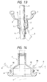
- the medium diameter portion 3 is structured such that the cylindrical diameter thereof is slightly widened in an inverted taper manner as it goes upwardly as shown in Fig. 13.
- the structure of the medium diameter portion 3 is useful in preventing the filler Z from slipping off, in view of the fact that the forming material of the grommet, that is, ethylene-propylene rubber has a poor adhesive force.
- the length of the cylindrical portion of the medium diameter portion 3 is of the order of 20mm, whereas the inside diameter (of the order of 30mm ⁇ ) of the upper end of the medium diameter portion 3 is larger about 1 - 5mm than the inside diameter of the lower end of the medium diameter portion 3.
- the leading end portion of the roof portion 2 is extended to thereby provide an inwardly facing flange 21 which extends in the central direction of the grommet.
- the flange portion 21 and the medium diameter portion 3 formed in an inverted taper shape cooperate together in preventing the filler Z, which has been cured within the medium diameter portion 3, from slipping off the medium diameter portion 3 downwardly.
- reference numeral 4 designates a small diameter portion which reduces in diameter continuously from the opening end of the medium diameter portion 3 and extends further upwardly from the opening end of the medium diameter portion 3 (Fig. 1).
- the small diameter portion 3 plays a role to guide and hold the wire harness 7 which is to be inserted through the grommet.
- the inside diameter (of the order of 15mm ⁇ ) of the small diameter portion 4 corresponds substantially to the bundle diameter of the wire harness 7, while the length of the small diameter portion 4 is of the order of 40mm.
- Reference numeral 41 stands for a guide piece which is provided by drawing out a portion of the opening edge from the small diameter portion 4.
- reference numeral 5 designates a through pipe for a hood cable, which is disposed such that it extends from the roof portion 2 along the inner wall of the base portion 1 and faces downwardly in the axial direction of the grommet.
- the through pipe 5 is sealed in the leading end thereof, while the leading end portion of the through pipe 5 is projected beyond the bottom surface of the base portion 1.
- 6 stands for a rear washer pipe which extends along the inner wall of the base portion 1 and is projected upwardly in the axial direction of the grommet from the roof portion 2.
- the rear washer pipe 6 is also sealed in the leading end thereof.
- Reference numeral 61 stands for a thick portion for a gate which is provided in the outer wall of the pipe 6 and is used for injection charging as shown in Fig. 7.
- the grommet thus structured is fitted with the opening 91 formed in the mating member 9, for example, the following procedure may be adopted.
- the wire harness 7 is inserted through the grommet.
- the opening edge 92 is slided on the upper inclined surface of the upper jaw portion 1b of the base portion 1 and is fitted into the mounting groove 11.
- the opening edge 92 is formed by punching it in a circular shape and the opening edge 92 includes such an inclined burring 93 as shown in Fig. 12, the opening edge 92 is fitted into the mounting groove 11 in such conditions as shown in Figs. 10 and 11.
- the lower jaw portion 1a is rotated with the annular cavity 19 portion as a fulcrum and this rotation of the lower jaw portion 1a produces around the annular cavity 19 a rubber elastic restitution which pushes back the lower jaw portion 1a.
- the seal ring portions 13, 14 and annular projection 16 can keep their pressure contact with the mating member 9, thereby being able to enhance their water preventive functions.
- the leading end of the burring 93 is in contact with the upper surface 18 of the mounting groove 11.
- seal ring portions 13 and 14 are disposed inwardly of the outside diameter of the base portion 1, they can perform their water preventive functions even if the opening edge 92 portion of the mating member 9 provides a small area of flat portion which is necessary for the purpose of water prevention.
- the provision of the annular cavity 19 allows the mounting groove 11 to be deformed flexibly, while the provision of the seal ring portions 13, 14 and annular projection 16 allows the grommet to be well fitted with the opening edge 92.
- the grommet according to the present embodiment as described before, there are provided five seal points at which the grommet is fitted with the mating member 9 in a pressure contact manner, thereby being able to secure an almost perfect water preventive function, that is, the present grommet is able to prevent water from invading into the vehicle room.
- the grommet is fitted with the opening edge 92 of the mating member 9 to thereby be able to perform a water preventive function
- a filler is loaded into the grommet in order to prevent invasion of water from between the wires forming the wire harness.
- the grommet according to the present embodiment is able to effectively cope with such case as well.
- the filler generally, there is employed a filler of a hardenable liquid type that it is liquid when it is loaded into the grommet and it hardens with the passage of time.
- the filler Z is loaded into the medium diameter portion 3 with the base portion 1 of the grommet facing upwardly as shown in Fig. 13.
- the roof portion 2 has a slope, the level of the liquid surface of the filler Z is lowered down from its initial position G while the filler Z penetrates into gaps between the wires, and the filler Z is finally stored into the medium diameter portion 3.
- the inwardly facing flange 21 serves as a stopper against the hardened filler Z and, therefore, even if the filler Z has a poor adhesion force with respect to the grommet, the filler Z is prevented against slippage. Also, since the medium diameter portion 3 is increased in diameter toward the small diameter portion 4, the filler Z within the medium diameter portion 3 is difficult to slip off not only toward the small diameter portion 4 side but also toward the roof portion 2 side, that is, the filler Z is held positively by the grommet, which allows the filler Z to provide a high water preventive function.
- the water preventive function of the grommet can be enhanced, whereas the portion (medium diameter portion 3) of the grommet into which the filler Z is loaded becomes hard. Therefore, when the wire harness 7 must be bent and disposed, the gaps S and M between the opening edge 92 of the mating member 9 and the base portion 1 of the grommet are widened, which results in a tendency to lower the sealing property of the grommet.
- the roof portion 2 and small diameter portion 4 can be deformed so as to make up for the hardened medium diameter portion 3, thereby preventing the base portion 1 from being deformed, so that the water preventive function of the base portion 1 cannot be lowered (this condition is shown by chained lines in Fig. 13).
- the conventional grommet when an external bending force is applied, the conventional grommet is bent as a whole and thus the bent center of gravity thereof is high (Fig. 16).
- the grommet according to the invention is bent in the neighborhood of the root of the medium diameter portion 3 and thus the bent center of gravity thereof is lowered, thereby allowing the grommet to cope with the extremely bent position of the wire harness 7 easily.
- the medium diameter portion 3 is an invertedly tapered cylindrical body, the medium diameter portion 3 is easy to bend in the narrow portion thereof which corresponds to the root portion thereof, which can lower the bent center of gravity of the grommet similarly to the above case.
- the through pipe 5 is formed so as to project beyond the bottom surface of the base portion 1, if the present grommet is applied to the vehicle using a hood cable, then the leading end of the through pipe 5 may be cut off, which can stabilize the sitting of the grommet. This is also a clear and great advantage when compared with the conventional grommet including a different type of through pipe. This makes it possible to find easily a careless mistake which could be made in the grommet assembling operation. Further, such projection of the through pipe 5 facilitates the setting of a jig.
- the present grommet is able to cope with the above-mentioned various cases and can be applied as a common part to various kinds of vehicles, which is also useful in managing an inventory and in reducing the cost of the grommet.
- the invention has been described heretofore using the above-mentioned embodiment thereof, the invention is not limited to this but it can be changed variously within the scope and spirit of the claims thereof according to the objects and uses.
- the size, shape, material and the like of the base portion 1, roof portion 2, medium diameter portion 3, small diameter portion 4, mounting groove 11, annular cavity 19, inwardly facing flange 21 and the like can be changed according to uses.
- the roof portion 2 may be formed in an umbrella shape, though the bending center of gravity thereof is higher.
- the annular cavity 19 may be formed in any portion of the inner wall surface of the base portion 1 existing in the connecting portion 1c or lower jaw portion 1a.
- the base portion of the grommet can be kept fitted with its mating member, which allows the grommet to fulfill a water preventive function. Also, if a filler is loaded into the medium diameter portion of the grommet while maintaining its water preventive function, then the grommet can also prevent invasion of water from between wires which form the wire harness. That is, the grommet according to the invention can provide excellent practical effects.
Landscapes
- Engineering & Computer Science (AREA)
- Architecture (AREA)
- Civil Engineering (AREA)
- Structural Engineering (AREA)
- Mechanical Engineering (AREA)
- Installation Of Indoor Wiring (AREA)
- Insulating Bodies (AREA)
Applications Claiming Priority (3)
| Application Number | Priority Date | Filing Date | Title |
|---|---|---|---|
| JP07943695A JP3322516B2 (ja) | 1995-03-09 | 1995-03-09 | グロメット |
| JP79436/95 | 1995-03-09 | ||
| JP7943695 | 1995-03-09 |
Publications (3)
| Publication Number | Publication Date |
|---|---|
| EP0731000A2 true EP0731000A2 (de) | 1996-09-11 |
| EP0731000A3 EP0731000A3 (de) | 1999-03-31 |
| EP0731000B1 EP0731000B1 (de) | 2001-06-27 |
Family
ID=13689836
Family Applications (1)
| Application Number | Title | Priority Date | Filing Date |
|---|---|---|---|
| EP96103671A Expired - Lifetime EP0731000B1 (de) | 1995-03-09 | 1996-03-08 | Durchführungstülle |
Country Status (4)
| Country | Link |
|---|---|
| US (1) | US5856635A (de) |
| EP (1) | EP0731000B1 (de) |
| JP (1) | JP3322516B2 (de) |
| DE (1) | DE69613499T2 (de) |
Cited By (7)
| Publication number | Priority date | Publication date | Assignee | Title |
|---|---|---|---|---|
| DE10230622A1 (de) * | 2002-07-03 | 2004-01-29 | Woco Franz Josef Wolf & Co. Gmbh | Tülle zum Durchführen und Halten länglicher Objekte |
| EP1489713A1 (de) * | 2003-06-17 | 2004-12-22 | Schneider Electric Industries SAS | Dichte Wanddurchführungsvorrichtung |
| DE10232715B4 (de) * | 2001-07-18 | 2007-01-11 | Yazaki Corp. | Gummidichtung |
| DE10232713B4 (de) * | 2001-07-18 | 2007-06-28 | Yazaki Corp. | Schallisolierende Gummidichtung für Kabelbaum |
| CN108351049A (zh) * | 2015-10-19 | 2018-07-31 | 利萨·德雷克塞迈尔有限责任公司 | 套管以及制造此类套管的方法 |
| CN110486469A (zh) * | 2018-05-14 | 2019-11-22 | 许继集团有限公司 | 柱上开关的箱体密封结构及密封圈 |
| DE102019125444A1 (de) * | 2019-09-20 | 2021-03-25 | Volkswagen Aktiengesellschaft | Vorrichtung zur Hindurchführung eines Kabels durch ein Blechelement und Montageverfahren |
Families Citing this family (44)
| Publication number | Priority date | Publication date | Assignee | Title |
|---|---|---|---|---|
| USRE38788E1 (en) | 1997-07-04 | 2005-09-06 | Sumitomo Wiring Systems, Ltd. | Grommet |
| JP3487495B2 (ja) * | 1998-04-24 | 2004-01-19 | 矢崎総業株式会社 | グロメット |
| JP2000041320A (ja) * | 1998-05-20 | 2000-02-08 | Yazaki Corp | グロメット |
| JP4091188B2 (ja) | 1998-12-09 | 2008-05-28 | 矢崎総業株式会社 | グロメットおよびグロメットの固定構造 |
| US6233140B1 (en) | 1999-01-22 | 2001-05-15 | Dell U.S.A., L.P. | Electrically conductive vibration dampener |
| JP3520797B2 (ja) * | 1999-03-02 | 2004-04-19 | 住友電装株式会社 | グロメット |
| JP3695636B2 (ja) * | 1999-06-02 | 2005-09-14 | 矢崎総業株式会社 | グロメット |
| US6348657B1 (en) * | 1999-07-06 | 2002-02-19 | John Haslock | Power cord sealing grommet and the like |
| US6582013B1 (en) * | 1999-11-09 | 2003-06-24 | Autonetworks Technologies, Ltd. | Vehicular ceiling assembling structure, a unit assembly used for the same, a frame member used for the same, and a vehicular ceiling assembling method |
| JP3501050B2 (ja) * | 1999-11-18 | 2004-02-23 | 住友電装株式会社 | グロメットおよび該グロメットのパネル取付方法 |
| JP2001177955A (ja) * | 1999-12-17 | 2001-06-29 | Sumitomo Wiring Syst Ltd | グロメットおよび該グロメットのパネル取付方法 |
| EP1745985B1 (de) * | 2000-01-11 | 2009-05-27 | Yazaki Corporation | Durchführungstülle |
| US6257923B1 (en) * | 2000-02-03 | 2001-07-10 | Phillips & Temro Industries Inc. | Dual media connector for a vehicle |
| JP2001231134A (ja) * | 2000-02-16 | 2001-08-24 | Sumitomo Wiring Syst Ltd | グロメット |
| JP3765220B2 (ja) * | 2000-03-15 | 2006-04-12 | 住友電装株式会社 | グロメット |
| US6603078B2 (en) * | 2000-09-22 | 2003-08-05 | Sumitomo Wiring Systems, Ltd. | Grommet |
| US6486400B1 (en) * | 2001-09-18 | 2002-11-26 | Delphi Technologies, Inc. | Acoustic grommet |
| JP3918486B2 (ja) | 2001-09-28 | 2007-05-23 | 住友電装株式会社 | グロメット |
| US6517648B1 (en) * | 2001-11-02 | 2003-02-11 | Appleton Papers Inc. | Process for preparing a non-woven fibrous web |
| JP2003164043A (ja) * | 2001-11-29 | 2003-06-06 | Yazaki Corp | グロメット |
| DE10225164A1 (de) * | 2002-06-06 | 2003-12-18 | Volkswagen Ag | Tülle für Leitungsdurchführungen |
| DE10332035B4 (de) * | 2002-08-07 | 2011-12-15 | Volkswagen Ag | Dichtungstülle für eine Leitungsdurchführung in einer Wandung |
| JP2004166431A (ja) * | 2002-11-14 | 2004-06-10 | Sumitomo Wiring Syst Ltd | グロメット |
| JP4036135B2 (ja) * | 2003-04-18 | 2008-01-23 | 住友電装株式会社 | グロメット |
| US6995317B1 (en) * | 2004-03-11 | 2006-02-07 | Excello Engineered Systems, Llc | Double wire pass through seal with grommets |
| US7244085B2 (en) * | 2004-04-26 | 2007-07-17 | Illinois Tool Works, Inc | Fastener assembly |
| TR200502100A2 (tr) * | 2005-06-03 | 2007-01-22 | Bsh Ev Aletler� Sanay� Ve T�Caret Anon�M ��Rket�@ | P |
| US7390969B2 (en) * | 2006-02-06 | 2008-06-24 | Toyota Motor Engineering & Manufacturing North America, Inc. | Wire harness grommet |
| US7915507B2 (en) * | 2006-11-16 | 2011-03-29 | Stephen Carol Onheiser | Methods and apparatus for mounting cymbals |
| JP5191178B2 (ja) * | 2007-07-04 | 2013-04-24 | 矢崎総業株式会社 | グロメット |
| US8108968B2 (en) * | 2009-02-17 | 2012-02-07 | GM Global Technology Operations LLC | Grommet assembly |
| US8262156B2 (en) | 2010-08-30 | 2012-09-11 | Toyota Motor Engineering & Manufacturing North America, Inc. | Wire harness guide and protector |
| DE102011054294A1 (de) * | 2011-10-07 | 2013-04-11 | Phoenix Contact Gmbh & Co. Kg | Kabeldurchführung und Verfahren zur Montage einer Kabeldurchführung |
| US8530761B2 (en) * | 2011-12-06 | 2013-09-10 | Ford Global Technologies, Llc | Grommet with service port having two closed ends |
| US20150040345A1 (en) * | 2013-08-06 | 2015-02-12 | Honda Motor Co., Ltd. | Vehicle grommet and method |
| US20150270640A1 (en) * | 2014-03-19 | 2015-09-24 | Donald Thomas | Trailer wiring connector |
| GB2521771A (en) * | 2014-12-19 | 2015-07-01 | Daimler Ag | Guide element for guiding lines extending through a pass-through |
| JP6424793B2 (ja) * | 2015-10-19 | 2018-11-21 | 住友電装株式会社 | グロメットおよびワイヤハーネス |
| US10556283B2 (en) * | 2017-12-19 | 2020-02-11 | Sumitomo Electric Wiring Systems, Ltd. | Grommet and method of making a grommet assembly |
| US10525908B2 (en) * | 2018-05-17 | 2020-01-07 | Kiekert Ag | Motor vehicle latching system with cable duct |
| JP7167729B2 (ja) * | 2019-01-21 | 2022-11-09 | 住友電装株式会社 | グロメット及びワイヤハーネス |
| US11396960B2 (en) * | 2020-03-12 | 2022-07-26 | Toyota Motor Engineering & Manufacturing North America, Inc. | Wire harness grommets with pull handles and methods of use |
| DE102021203267B3 (de) * | 2021-03-31 | 2022-06-09 | Motherson Innovations Company Limited | Außenrückblickanordnung und Dichtung |
| DE102022208776A1 (de) | 2022-08-25 | 2024-03-07 | Leoni Bordnetz-Systeme Gmbh | Abdichtvorrichtung zum Abdichten eines durch eine Durchgangsöffnung zu führenden Leitungsstrangs gegen die Durchgangsöffnung, Kabelsatz oder Kit oder Kraftfahrzeug mit einer solchen Abdichtvorrichtung sowie entsprechendes Abdichtverfahren |
Citations (4)
| Publication number | Priority date | Publication date | Assignee | Title |
|---|---|---|---|---|
| JPH04249817A (ja) * | 1990-12-28 | 1992-09-04 | Fujikura Ltd | グロメット |
| JPH06217439A (ja) * | 1993-01-11 | 1994-08-05 | Yazaki Corp | グロメットのワイヤハーネスへの組付け方法 |
| JPH06231643A (ja) * | 1993-02-05 | 1994-08-19 | Yazaki Corp | グロメット |
| JPH0729439A (ja) * | 1993-07-09 | 1995-01-31 | Sumitomo Wiring Syst Ltd | ワイヤハーネス一体型グロメット及びその成形方法 |
Family Cites Families (8)
| Publication number | Priority date | Publication date | Assignee | Title |
|---|---|---|---|---|
| FR1307295A (fr) * | 1961-09-11 | 1962-10-26 | Legrand Ets | Bague de passage étanche d'un câble à travers une paroi |
| FR1342949A (fr) * | 1962-10-04 | 1963-11-15 | Perfectionnements aux dispositifs obturateurs, passe-fils et analogues | |
| US5138117A (en) * | 1987-07-09 | 1992-08-11 | Yazaki Corporation | Watertight sealing lip for grommet |
| JPH0616192Y2 (ja) * | 1988-12-27 | 1994-04-27 | トヨタ自動車株式会社 | ワイヤハーネス用グロメット |
| EP0580130A1 (de) * | 1992-07-21 | 1994-01-26 | Ichikoh Industries Limited | Leitungsdurchführungspfropfen |
| JP2787794B2 (ja) * | 1993-02-02 | 1998-08-20 | 矢崎総業株式会社 | グロメット防水構造 |
| JP3327988B2 (ja) * | 1993-04-22 | 2002-09-24 | 矢崎総業株式会社 | グロメット |
| JPH0714452A (ja) * | 1993-06-24 | 1995-01-17 | Yazaki Corp | グロメット |
-
1995
- 1995-03-09 JP JP07943695A patent/JP3322516B2/ja not_active Expired - Fee Related
-
1996
- 1996-03-08 EP EP96103671A patent/EP0731000B1/de not_active Expired - Lifetime
- 1996-03-08 DE DE69613499T patent/DE69613499T2/de not_active Expired - Fee Related
-
1997
- 1997-10-31 US US08/962,119 patent/US5856635A/en not_active Expired - Lifetime
Patent Citations (4)
| Publication number | Priority date | Publication date | Assignee | Title |
|---|---|---|---|---|
| JPH04249817A (ja) * | 1990-12-28 | 1992-09-04 | Fujikura Ltd | グロメット |
| JPH06217439A (ja) * | 1993-01-11 | 1994-08-05 | Yazaki Corp | グロメットのワイヤハーネスへの組付け方法 |
| JPH06231643A (ja) * | 1993-02-05 | 1994-08-19 | Yazaki Corp | グロメット |
| JPH0729439A (ja) * | 1993-07-09 | 1995-01-31 | Sumitomo Wiring Syst Ltd | ワイヤハーネス一体型グロメット及びその成形方法 |
Non-Patent Citations (4)
| Title |
|---|
| PATENT ABSTRACTS OF JAPAN vol. 017, no. 022 (E-1307), 14 January 1993 & JP 04 249817 A (FUJIKURA LTD), 4 September 1992 * |
| PATENT ABSTRACTS OF JAPAN vol. 018, no. 586 (E-1627), 9 November 1994 & JP 06 217439 A (YAZAKI CORP), 5 August 1994 * |
| PATENT ABSTRACTS OF JAPAN vol. 018, no. 595 (E-1630), 14 November 1994 & JP 06 231643 A (YAZAKI CORP), 19 August 1994 * |
| PATENT ABSTRACTS OF JAPAN vol. 095, no. 004, 31 May 1995 & JP 07 029439 A (SUMITOMO WIRING SYST LTD), 31 January 1995 * |
Cited By (9)
| Publication number | Priority date | Publication date | Assignee | Title |
|---|---|---|---|---|
| DE10232715B4 (de) * | 2001-07-18 | 2007-01-11 | Yazaki Corp. | Gummidichtung |
| DE10232713B4 (de) * | 2001-07-18 | 2007-06-28 | Yazaki Corp. | Schallisolierende Gummidichtung für Kabelbaum |
| DE10230622A1 (de) * | 2002-07-03 | 2004-01-29 | Woco Franz Josef Wolf & Co. Gmbh | Tülle zum Durchführen und Halten länglicher Objekte |
| DE10230622B4 (de) * | 2002-07-03 | 2004-08-12 | Woco Industrietechnik Gmbh | Tülle zum Durchführen und Halten länglicher Objekte |
| EP1489713A1 (de) * | 2003-06-17 | 2004-12-22 | Schneider Electric Industries SAS | Dichte Wanddurchführungsvorrichtung |
| FR2856529A1 (fr) * | 2003-06-17 | 2004-12-24 | Schneider Electric Ind Sas | Dispositif de traversee etanche de paroi. |
| CN108351049A (zh) * | 2015-10-19 | 2018-07-31 | 利萨·德雷克塞迈尔有限责任公司 | 套管以及制造此类套管的方法 |
| CN110486469A (zh) * | 2018-05-14 | 2019-11-22 | 许继集团有限公司 | 柱上开关的箱体密封结构及密封圈 |
| DE102019125444A1 (de) * | 2019-09-20 | 2021-03-25 | Volkswagen Aktiengesellschaft | Vorrichtung zur Hindurchführung eines Kabels durch ein Blechelement und Montageverfahren |
Also Published As
| Publication number | Publication date |
|---|---|
| EP0731000A3 (de) | 1999-03-31 |
| EP0731000B1 (de) | 2001-06-27 |
| JP3322516B2 (ja) | 2002-09-09 |
| US5856635A (en) | 1999-01-05 |
| DE69613499D1 (de) | 2001-08-02 |
| JPH08251770A (ja) | 1996-09-27 |
| DE69613499T2 (de) | 2002-01-17 |
Similar Documents
| Publication | Publication Date | Title |
|---|---|---|
| EP0731000B1 (de) | Durchführungstülle | |
| US5739475A (en) | Grommet for protecting a wire harness with structure for ensuring flush seating | |
| US6211464B1 (en) | Grommet having resilient flange for mounting on a panel | |
| EP0823763B1 (de) | Durchführungshülle | |
| JP2947000B2 (ja) | ワイヤハーネスの防水方法および防水構造 | |
| JP2005016718A (ja) | 金属/プラスチックのインサート成形シールプレートファスナ | |
| US5337447A (en) | Grommet | |
| US5499823A (en) | Grommet with filler inlet opening | |
| US6339196B1 (en) | Grommet | |
| US7020931B1 (en) | Grommet and retainer | |
| US10840632B2 (en) | Grommet with deformable seal | |
| US20110079417A1 (en) | Grommet | |
| JP3431273B2 (ja) | グロメット | |
| US4679698A (en) | Fuel tank filler tube restrictor assembly | |
| JP3535139B2 (ja) | グロメット | |
| JP4029722B2 (ja) | グロメット | |
| JPH05198228A (ja) | グロメット | |
| EP1013508B1 (de) | Tülle mit elastischer Flansch zur Befestigung auf einer Tafel | |
| JP3794607B2 (ja) | グロメット | |
| JPH08167339A (ja) | グロメット | |
| JP3354530B2 (ja) | 配線防護部材の取り付け構造 | |
| JP2004187354A (ja) | グロメット | |
| JP3293511B2 (ja) | シール構造 | |
| JPH08316658A (ja) | グロメット | |
| WO2021181921A1 (ja) | 燃料ポンプ接続部の保護構造 |
Legal Events
| Date | Code | Title | Description |
|---|---|---|---|
| PUAI | Public reference made under article 153(3) epc to a published international application that has entered the european phase |
Free format text: ORIGINAL CODE: 0009012 |
|
| AK | Designated contracting states |
Kind code of ref document: A2 Designated state(s): DE FR GB |
|
| PUAL | Search report despatched |
Free format text: ORIGINAL CODE: 0009013 |
|
| AK | Designated contracting states |
Kind code of ref document: A3 Designated state(s): DE FR GB |
|
| 17P | Request for examination filed |
Effective date: 19990528 |
|
| GRAG | Despatch of communication of intention to grant |
Free format text: ORIGINAL CODE: EPIDOS AGRA |
|
| 17Q | First examination report despatched |
Effective date: 20000920 |
|
| GRAG | Despatch of communication of intention to grant |
Free format text: ORIGINAL CODE: EPIDOS AGRA |
|
| GRAH | Despatch of communication of intention to grant a patent |
Free format text: ORIGINAL CODE: EPIDOS IGRA |
|
| GRAH | Despatch of communication of intention to grant a patent |
Free format text: ORIGINAL CODE: EPIDOS IGRA |
|
| GRAA | (expected) grant |
Free format text: ORIGINAL CODE: 0009210 |
|
| AK | Designated contracting states |
Kind code of ref document: B1 Designated state(s): DE FR GB |
|
| REF | Corresponds to: |
Ref document number: 69613499 Country of ref document: DE Date of ref document: 20010802 |
|
| ET | Fr: translation filed | ||
| REG | Reference to a national code |
Ref country code: GB Ref legal event code: IF02 |
|
| PLBE | No opposition filed within time limit |
Free format text: ORIGINAL CODE: 0009261 |
|
| STAA | Information on the status of an ep patent application or granted ep patent |
Free format text: STATUS: NO OPPOSITION FILED WITHIN TIME LIMIT |
|
| 26N | No opposition filed | ||
| PGFP | Annual fee paid to national office [announced via postgrant information from national office to epo] |
Ref country code: GB Payment date: 20090304 Year of fee payment: 14 |
|
| PGFP | Annual fee paid to national office [announced via postgrant information from national office to epo] |
Ref country code: DE Payment date: 20090306 Year of fee payment: 14 |
|
| PGFP | Annual fee paid to national office [announced via postgrant information from national office to epo] |
Ref country code: FR Payment date: 20090316 Year of fee payment: 14 |
|
| GBPC | Gb: european patent ceased through non-payment of renewal fee |
Effective date: 20100308 |
|
| REG | Reference to a national code |
Ref country code: FR Ref legal event code: ST Effective date: 20101130 |
|
| PG25 | Lapsed in a contracting state [announced via postgrant information from national office to epo] |
Ref country code: FR Free format text: LAPSE BECAUSE OF NON-PAYMENT OF DUE FEES Effective date: 20100331 |
|
| PG25 | Lapsed in a contracting state [announced via postgrant information from national office to epo] |
Ref country code: DE Free format text: LAPSE BECAUSE OF NON-PAYMENT OF DUE FEES Effective date: 20101001 |
|
| PG25 | Lapsed in a contracting state [announced via postgrant information from national office to epo] |
Ref country code: GB Free format text: LAPSE BECAUSE OF NON-PAYMENT OF DUE FEES Effective date: 20100308 |