EP0678934B1 - Ein- oder mehrpoliger Querverbinder für Anschlussklemme - Google Patents
Ein- oder mehrpoliger Querverbinder für Anschlussklemme Download PDFInfo
- Publication number
- EP0678934B1 EP0678934B1 EP94119791A EP94119791A EP0678934B1 EP 0678934 B1 EP0678934 B1 EP 0678934B1 EP 94119791 A EP94119791 A EP 94119791A EP 94119791 A EP94119791 A EP 94119791A EP 0678934 B1 EP0678934 B1 EP 0678934B1
- Authority
- EP
- European Patent Office
- Prior art keywords
- contact
- comb
- spring
- cross connector
- pin
- Prior art date
- Legal status (The legal status is an assumption and is not a legal conclusion. Google has not performed a legal analysis and makes no representation as to the accuracy of the status listed.)
- Expired - Lifetime
Links
- 230000005405 multipole Effects 0.000 title description 3
- 239000002184 metal Substances 0.000 claims description 3
- 229910052751 metal Inorganic materials 0.000 claims description 3
- 239000004020 conductor Substances 0.000 claims description 2
- 230000000694 effects Effects 0.000 claims description 2
- 239000000463 material Substances 0.000 description 11
- 210000001520 comb Anatomy 0.000 description 8
- 238000004519 manufacturing process Methods 0.000 description 6
- 238000003780 insertion Methods 0.000 description 4
- 230000037431 insertion Effects 0.000 description 4
- 239000002994 raw material Substances 0.000 description 3
- 238000010276 construction Methods 0.000 description 2
- 210000003746 feather Anatomy 0.000 description 2
- 238000000034 method Methods 0.000 description 2
- 230000003287 optical effect Effects 0.000 description 2
- 230000036316 preload Effects 0.000 description 2
- 229910001369 Brass Inorganic materials 0.000 description 1
- RYGMFSIKBFXOCR-UHFFFAOYSA-N Copper Chemical compound [Cu] RYGMFSIKBFXOCR-UHFFFAOYSA-N 0.000 description 1
- 101000952234 Homo sapiens Sphingolipid delta(4)-desaturase DES1 Proteins 0.000 description 1
- 102100037416 Sphingolipid delta(4)-desaturase DES1 Human genes 0.000 description 1
- 238000005452 bending Methods 0.000 description 1
- 230000009286 beneficial effect Effects 0.000 description 1
- 239000010951 brass Substances 0.000 description 1
- 229910052802 copper Inorganic materials 0.000 description 1
- 239000010949 copper Substances 0.000 description 1
- 238000010292 electrical insulation Methods 0.000 description 1
- 238000005516 engineering process Methods 0.000 description 1
- 238000001125 extrusion Methods 0.000 description 1
- 239000004615 ingredient Substances 0.000 description 1
- 230000000717 retained effect Effects 0.000 description 1
- 238000007493 shaping process Methods 0.000 description 1
- 238000003860 storage Methods 0.000 description 1
- 230000000007 visual effect Effects 0.000 description 1
- 238000003466 welding Methods 0.000 description 1
Images


Classifications
-
- H—ELECTRICITY
- H01—ELECTRIC ELEMENTS
- H01R—ELECTRICALLY-CONDUCTIVE CONNECTIONS; STRUCTURAL ASSOCIATIONS OF A PLURALITY OF MUTUALLY-INSULATED ELECTRICAL CONNECTING ELEMENTS; COUPLING DEVICES; CURRENT COLLECTORS
- H01R13/00—Details of coupling devices of the kinds covered by groups H01R12/70 or H01R24/00 - H01R33/00
- H01R13/02—Contact members
- H01R13/15—Pins, blades or sockets having separate spring member for producing or increasing contact pressure
- H01R13/17—Pins, blades or sockets having separate spring member for producing or increasing contact pressure with spring member on the pin
-
- H—ELECTRICITY
- H01—ELECTRIC ELEMENTS
- H01R—ELECTRICALLY-CONDUCTIVE CONNECTIONS; STRUCTURAL ASSOCIATIONS OF A PLURALITY OF MUTUALLY-INSULATED ELECTRICAL CONNECTING ELEMENTS; COUPLING DEVICES; CURRENT COLLECTORS
- H01R31/00—Coupling parts supported only by co-operation with counterpart
- H01R31/08—Short-circuiting members for bridging contacts in a counterpart
- H01R31/085—Short circuiting bus-strips
-
- H—ELECTRICITY
- H01—ELECTRIC ELEMENTS
- H01R—ELECTRICALLY-CONDUCTIVE CONNECTIONS; STRUCTURAL ASSOCIATIONS OF A PLURALITY OF MUTUALLY-INSULATED ELECTRICAL CONNECTING ELEMENTS; COUPLING DEVICES; CURRENT COLLECTORS
- H01R9/00—Structural associations of a plurality of mutually-insulated electrical connecting elements, e.g. terminal strips or terminal blocks; Terminals or binding posts mounted upon a base or in a case; Bases therefor
- H01R9/22—Bases, e.g. strip, block, panel
- H01R9/24—Terminal blocks
- H01R9/26—Clip-on terminal blocks for side-by-side rail- or strip-mounting
- H01R9/2675—Electrical interconnections between two blocks, e.g. by means of busbars
Definitions
- the invention relates to a cross connector with the features of the preamble of claim 1.
- Such cross connectors are used to connect multiple busbars or several terminals to switch to the same electrical potential.
- a multi-pole cross connector is used to insert the individual poles into the Busbars of several terminals. In this way, busbars are different Terminals switched to the same electrical potential.
- the contact pins have a correspondingly shaped slot in the busbars.
- a contact spring is effectively assigned to each contact pin on the busbar.
- the spring force of the contact spring is normally perpendicular to the longitudinal axis or effective to the flat plane of the contact pin. The one inserted in the rail slot As a result, the contact pin is clamped to the busbar.
- a cross connector of the type mentioned which consists of two essentially plane-parallel, one Made sheet metal contact combs, which are essentially identical connected to each other in the area of the crosshead of their comb shape are.
- the crest-like contact pins there including an air gap bent apart between them.
- the two to the cross connector with each other Combined contact combs are identical in terms of material and shape and to each other positioned in mirror image.
- the invention has for its object a cross connector of the aforementioned To simplify its structure and its functionality improve. This object is solved by claim 1.
- the contact pin and the Contact springs directly against each other and are mechanically stable with each other connected.
- the entire cross connector is in the assembled state essentially alignable in a single level.
- the very flat structure of the Cross connector enables easy manual handling.
- the recording rooms The clamps for the cross connector can be because of its very simple and flat geometric structure can also be manufactured more easily.
- the receiving spaces of the terminals can be made smaller, so that the recording rooms and the busbars lying in front possible mechanical damage are better protected.
- the material selection of the contact spring can only be based on mechanical Criteria for a good spring action occur because the electrical contacting of the Cross connector with one or more terminals already over the Contact pins is made. Depending on the expediency, the electrical contacting the clamping connector with the busbars are improved, by the material of the contact spring also good electrical conductivity has, so that its effective electrical in the inserted state of the cross connector Contact area with the busbars is enlarged.
- the contact pins form the comb teeth of a comb-like Formed. They are aligned in the row direction of the contact pins metallic cross bar mechanically and electrically connected to each other. This contact comb switches the desired in by means of its contact pins Direction of adjacent busbars of several terminals to the same electrical potential.
- the cross connector consists essentially of the contact comb, the contact springs and the appropriate fasteners. Ease these few components warehousing and thus reduce storage and logistics costs of the cross connector. The few components also promote mechanical inherent stability of the cross connector. They also contribute to a variety of wear-prone connecting means between individual components save.
- the contact comb alone already has sufficient mechanical properties Stability as it is a sufficient current-carrying element Cable cross-section must be available.
- Fasten contact springs as individual parts directly on the contact comb.
- the Contact springs can then be made from a strip material with the cross-sectional dimensions the contact spring.
- the preformed tape material is thereby from the direction perpendicular to the longitudinal extension of the contact comb fed to the associated contact pin of the contact comb and in one Work step fastened and cut off.
- the particular advantage of this manufacturing method is that the contact springs are made waste-free and the Blank of the cross connector can be stored in endless format.
- Claim 3 proposes a simple connection technology for the mechanically stable Attach the contact springs to the assigned contact pins.
- Claim 4 takes into account that the attachment point between the contact pin and contact spring outside the components to be inserted into the terminals of the cross connector. Therefore, the liaison office is Insert into the terminals or by pulling them out of the terminals not damaged. The stable attachment between the contact pin and contact spring is retained over a very long period of operation.
- the contact springs are part of a comb-like structure.
- This spring comb can be manufactured in a structurally simple manner.
- the simple one Construction supports the easy assembly of the cross connector.
- the spring comb carries the contact springs.
- the contact springs must therefore not be mounted individually on the cross connector. Rather, the Attach the entire spring comb to the contact comb in a single step.
- the contact comb and the spring comb are usually the contact pins or contact springs connecting mechanically with each other connected. Since the bracket, i.e. the cross bar and the spring clip are aligned in the row of the contact pins is the inherent stability of the cross connector further improved along the row direction.
- Claim 6 supports the technically simple manufacture and inherent stability the feather comb.
- the contact comb and the spring comb according to claim 7 are approximately in one single level.
- raw material for such contact or spring combs a variety of metallic plate or sheet materials are inexpensive to disposal.
- the processing of these raw materials to the contact comb or to the spring comb is done in very few steps.
- the Working steps themselves are technically very simple with few manufacturing machines feasible.
- the raw materials essentially have to just cut and punched.
- the geometric shape of the contact pin and the contact spring or the contact comb and the spring comb as a fixing aid be used during their assembly.
- the approximately congruent system supports the effect of Cross connector as a compact unit, which due to missing projections or other geometrical deviations of individual components from the overall shape the cross connector improved protected against mechanical damage is.
- the contact spring is structurally particularly simple. Designed as a leaf spring, the contact spring combines easily Way the flat, compact structure of the cross connector with a good Spring action of the spring comb.
- a cross connector according to claim 11 is suitable, not only the busbars lined up clamps, but also two or more To connect busbars of the same terminal to each other with the same potential
- the busbars are then in the longitudinal direction of the pin in the Clamp, e.g. in a multi-level terminal block, one above the other.
- To the pole or the poles of the cross connector are appropriate for this purpose extended in the longitudinal direction of the pin and each have at least two in the longitudinal direction of the pin spaced apart terminal contact points, which the are assigned to respective busbars. It is conceivable to be constructive to use pole constructed in this way for a single-pole cross connector. It is also conceivable that in a multipole cross connector or all poles are constructed according to claim 11.
- Such one Cross connector can with a corresponding stringing of Use tier terminal blocks and terminals with a single busbar.
- Claim 12 proposes a simple measure for electrical insulation of the areas of the surface normally used as handling surfaces Cross connector during the insertion process or while loosening the busbars.
- the insulating jacket can e.g. through an appropriate plastic extrusion the cross bar and the adjoining areas of the contact pins and the contact springs are manufactured.
- Another way to Production of the insulating jacket consists of the components to be encased insert the cross connector into two preformed insulating half shells. The two insulating half-shells are then interposed with the Cross connector e.g. connected in one piece by welding.
- Claim 13 supports the easy handling of the cross connector an operator.
- One or more jacket slots according to claim 14 can further Simplify the handling of the cross connector as a target for one Tool, e.g. a screwdriver. This allows the cross connector Detach from the busbars without any significant effort.
- the jacket slot can be used as a fixing aid for one to be attached to the cross connector optical marking can be used. This will e.g. Confusion of individual cross connectors arranged in the row direction avoided by an operator.
- each contact pin is assigned a jacket slot.
- the jacket slots are equipped identically and in the row direction lined up at a constant distance. This allows a tool the most effective at the moment in the row connector in its row direction Apply the point of attack.
- the jacket slots allow simple visual identification of all contact pins of the cross connector. This can e.g. Predefined references to a very specific row direction arranged and to be switched to a certain electrical potential Clamps.
- the recesses also allow a comfortable Exchange of fixed optical markings. That way you can any incorrect information for an operator can be easily corrected.
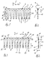
- a contact comb 1 is shown as part of a cross connector 2.
- the contact comb 1 with its comb-like cross-sectional shape is electrical conductive and punched out of a metal plate.
- a total of ten identical contact pins 3 are arranged. They form the Comb teeth of the contact comb 1 and are 4 in a row direction evenly spaced from each other.
- the contact pins 3 are in a pin longitudinal direction 5 arranged at right angles to the row direction 4 aligned.
- the cross connector 2 is in the busbars the terminals not shown in the figures or deducted from the power rails.
- the contact pins 3 are in one piece with a extending in the row direction 4 Cross bar 6 connected. On the cross bar 6 there are a total of ten fixing pins 7 molded. They are arranged in the row direction 4. The center of the im Cross section of circular fixing pin 7 lies on the imaginary extension a pin symmetry axis 8 running in the longitudinal direction 5 of the pin. The contact pin 3 is constructed symmetrically with respect to the pin symmetry axis 8.
- Fig. 2 it can be seen that the fixing pin 7 by lifting out the material the cross bar 6 are formed in the depth direction 9.
- the depth direction 9 is arranged at right angles to the row direction 4 and the pin longitudinal direction 5. 2 that the contact comb 1 in the depth direction 9 is built very flat and essentially in a single level, namely the ridge plane.
- the ridge plane is through the row direction 4 and the pin longitudinal direction 5 spanned.
- the contact pin 3 has a predetermined breaking point.
- the contact pin 3 recessed on both sides of its pin symmetry axis 8 by a pin groove 10 each.
- the pin grooves 10 are approximately half the pin length of the contact pin 3 arranged.
- the contact pins 3 that can be detached at the predetermined breaking point ensure that the cross connector 2 reliably bridges such terminals, which are within the selected row, but not on the electrical one Potential should be switched.
- the flat plane of the contact pin 3 has two different ones along its pin length Spread out.
- the wider area immediately follows the Cross bar 6.
- the narrower area is the cross bar 6 in the longitudinal direction of the pin 5 arranged facing away and contains the free end of the contact pin 3.
- the wider and the narrower area of the contact pin 3 are by two 5 heel edges connected obliquely to the longitudinal direction of the pin.
- the heel edges act as limit stops 18. You limit the travel of the cross connector 2 during its insertion the power rails of the terminals and also allow a good fit of the Cross connector 2 on the power rails.
- FIG. 3 is a spring comb 11 with a comb-like Cross-sectional shape shown.
- the spring comb 11 is also very flat built up and therefore lies essentially in a single level. During assembly, the spring comb 11 is directly on the contact comb 1 created (Fig. 6). The comb plane of the spring comb 11 is therefore also spanned by the row direction 4 and the pin longitudinal direction 5.
- the spring comb 11 consists of a spring clip running in the row direction 4 12 and integrally molded contact springs 13.
- the spring comb 11 has a total of ten contact springs 13. They form the comb teeth of the spring comb 11 and are in the row direction 4 in a uniform manner Distance strung together.
- each contact pin 3 is one Contact spring 13 assigned.
- the contact spring 13 has an approximately rectangular cross-sectional shape and extends in the longitudinal direction 5 approximately as far as the contact pin 3.
- the spring force the part producing the contact spring 13 is that of the spring clip 12 in the longitudinal direction of the pin 5 remote area of the contact spring 13.
- This Surface area is referred to as spring area 14. 4 it can be clearly seen that that the spring region 14 is designed in the manner of a leaf spring.
- the spring area 14 is in the longitudinal direction 5 of the pin by an adjoining the spring clip 12 Spring-fixed end 15 and a spring-free end 16 limited. Between the spring end 15 and the spring free end 16 is the spring region 14 with a Clamp contact point 17 relative to the comb plane of the spring comb 11 slightly bent out and thereby mechanically pre-tensioned.
- the preload creates a spring force in the depth direction 9.
- the terminal contact point 17 forms the at Stromschlene immediately adjacent surface area of the contact spring 13, as soon as the contact pin 3 is inserted into the current axis. With appropriate Material selection for the spring comb 11 can be done by the clamping contact point 17 also serve as a good electrical contact on the busbar.
- the spring clip 12 is pierced by ten fixing recesses 19. While the assembly of the cross connector 2 passes through each fixing pin 7 fixing recess 19 assigned to it. In this way, the fixing recesses serve 19 as an assembly aid when applying the spring comb 11 the contact comb 1. After applying the spring comb 11 to the contact comb 1, the fixing pins 7 are caulked. This creates a mechanical stable attachment between the contact comb 1 and the spring comb 11.
- FIGS Fig. 6 The combs 1, 11 connected to one another in this way are shown in FIGS Fig. 6 shown.
- the blank is of the cross connector 2 in the case of fully automatic production by the application and fastening individual contact springs 13.
- Cross connector 2 differs from the exemplary embodiment according to 5 only by the lack of the spring clip 12.
- the spring comb 11 in FIGS. 5 and 6 is approximately plane-parallel and congruent directly on the contact comb 1.
- the two combs are 1.11 thereby in the same, through the row direction 4 and the pin longitudinal direction 5 spanned level.
- the spring fixed end 15 of the contact spring 13 is approximately arranged in the region of the pin groove 10 of the contact pin 3.
- the spring-free end 16 of the contact spring 13 lies on the one aligned in the longitudinal direction 5 of the pin Free end of the contact pin 3. Due to the mechanical preload of the spring area 14 is between the contact pin 3 and the contact area 17 a small air gap.
- the cross section of the spring area 14 facilitates the insertion of the contact pin 3 in a corresponding shaped slot of the power rail while ensuring good Clamp contacting of contact pin 3 with the busbar.
- the combs 1, 11 connected to one another are of an insulating jacket 20 surrounded by a form or material fit. It protrudes in row direction 4 slightly the contact comb 1.
- the insulating jacket protrudes in the longitudinal direction 5 of the pin 20 also the contact comb 1.
- In this protruding area is the Insulating jacket 20 broken through a total of ten identical jacket slots 21. They have a rectangular cross-sectional shape with 4 in the row direction running longitudinal edge. They are equally spaced in the row direction 4 strung together.
- Each jacket slot 21 is assigned a contact pin 3.
- the insulating jacket 20 also surrounds that of the cross bar 6 or the spring clip 12 adjacent surface areas of the contact pins 3 or the contact springs 13.
- the pin grooves 10 must remain free so that the relevant contact pin 3, if necessary this predetermined breaking point can be severed.
- the cross-sectional shape of the insulating jacket 20 is also comb-like. His comb teeth surround the mentioned surface areas of the contact pins 3 and the contact springs 13.
- FIGS. 1 to 7 While in FIGS. 1 to 7, a 10-pole embodiment of the cross connector 2 is shown, in Fig. 8 is a 2-pin embodiment of the cross connector 2 recognizable with two contact pins 3.
- the two combs are 1.11 designed accordingly U-shaped.
- the insulating jacket 20 in Fig. 8 has in Area between his jacket slot 21 and his two comb teeth a plurality of grip grooves 22 extending in the row direction.
- the two combs 1, 11 according to FIGS. 1 to 9 are each with any one Number of poles can be manufactured in one piece. Accordingly, the cross connector 2 in other embodiments, n contact pins 3, where 2 ⁇ n ⁇ .
- FIG. 10 shows a further 10-pin embodiment of the cross connector 2 shown.
- This cross connector 2 differs from the embodiment 7 only by contact pins 3 elongated in the longitudinal direction 5 of the pin and accordingly extended contact springs 13.
- each contact spring 13 has two clamping contact points 17 on.
- the contact spring 13 contains two in the longitudinal direction of the pin 5 rows of spring areas 14 (FIG. 12).
- Such one Cross connector 2 is used to connect two busbars with the same potential the same terminal block, e.g. a tier terminal block.
- the two Busbars are arranged one above the other in the manner of a tier in the longitudinal direction 5 of the pin In this way, the individual poles of the cross connector are clamped 2 according to FIGS. 10 to 12 each have two busbars as soon as the Cross connector 2 is inserted in the multi-level terminal blocks.
- Such individual ones are in further exemplary embodiments, not shown here Poles of the cross connector 2 in the longitudinal direction 5 further extended and point accordingly more than two terminal contact points 17.
- Such one Cross connector 2 is suitable for use in multi-level terminal blocks suitable with more than two busbars.
Landscapes
- Coupling Device And Connection With Printed Circuit (AREA)
- Connections Effected By Soldering, Adhesion, Or Permanent Deformation (AREA)
Description
- Fig. 1
- eine Draufsicht eines 10-poligen Kontaktkammes mit seinen Kontaktstiften,
- Fig. 2
- die Seitenansicht des Kontaktkammes entsprechend der Schnittlinie II-II in Fig. 1,
- Fig. 3
- eine Draufsicht eines 10-poligen Federkammes mit seinen Kontaktfedern,
- Fig. 4
- die Seitenansicht des Federkammes entsprechend der Schnittlinie IV-IV In Fig. 3,
- Fig. 5
- die Draufsicht des Kontaktkammes und des Federkammes in ihrem Montagezustand,
- Fig. 6
- die Seitenansicht des 1 0-poligen Querverbinders entsprechend der Schnittlinie VI-VI in Fig. 5,
- Fig. 7
- die Darstellung des Querverbinders gemäß Fig. 6 und daran fixiertem Isoliermantel,
- Fig. 8
- die Darstellung einer 2-poligen Ausführungsform des Querverbinders gem. Fig. 7.
- Fig. 9
- die Seitenansicht des Querverbinders entsprechend der Schnittlinie IX-IX in Fig. 7,
- Fig. 10
- die Darstellung des Querverbinders gemäß Fig. 7, jedoch mit verlängerten Polen zur potentialgleichen Verbindung zweier Stromschienen derselben Anschlußklemme,
- Fig. 11
- die Darstellung einer einpoligen Ausführungsform des Querverbinders gemäß Fig. 10,
- Fig. 12
- die Seitenansicht des Querverbinders entsprechend der Schnittlinie XII-XII in Fig. 10.
Claims (14)
- Querverbinder (2) für Anschluß- und/oder Verbindungsklemmen, insbesondere für Reihenklemmen, mit einer Querleiste (6) und kammzinkenartig von dieser abstehenden Kontaktstiften (3) in Form von Flachsteckern, die mit einem federnden Bereich 14 in Stecköffnungen von Stromschienen der in einer Reihe nebeneinander angeordneten Klemmen festsetzbar und elektrisch kontaktierbar sind,
dadurch gekennzeichnet,
daß der Querverbinder (2) einen aus einer Metallplatte gestanzten, im wesentlichen ebenen Kontaktkamm (1) mit einem seiner Funktion als stromtragendes Element genügenden Leitungsquerschnitt als Stabilitätsbildner enthält, dessen Kontaktstifte (3) an einer Flachseite von mit ihrer Flachseite zugewandten blattfederartigen Kontaktfedern (13) flankiert sind, diean ihrem in Steckrichtung hinteren Ende (15) am Kontaktkamm (1) fixiert sind,mit ihrem in Steckrichtung vorderen Ende (16) am Steckende des Kontaktstiftes (3) anliegen unddazwischen zur Erzeugung eines in eingestecktem Zustand wirksamen, lateralen Kontakffederdruckes durch einen Luftspalt von den Kontaktstiften distanziert sind. - Querverbinder nach Anspruch 1,
gekennzeichnet durch
eine Verstemmung zur Befestigung der Kontakffedern (13) am Konkaktkamm (1). - Querverbinder nach einem der Ansprüche 1 oder 2,
dadurch gekennzeichnet,
daß die Kontaktfeder (13) mit einem Federfestende (15) am Kontaktstift (3) oder an der Querleiste (6) des Kontaktkammes (1) befestigt ist. - Querverbinder nach einem der Ansprüche 2 bis 4,
dadurch gekennzeichnet,
daß die Kontaktfedern (13) an ihren Federfestenden (15) durch einen Federbügel (12) miteinander verbunden sind und dadurch die Kammzinken eines Federkammes (11) bilden. - Querverbinder nach Anspruch 4,
dadurch gekennzeichnet,
daß der Federkamm (11) einstückig hergestellt ist. - Querverbinder nach Anspruch 4 oder 5,
dadurch gekennzeichnet,
daß der gesamte Federkamm (11) und der Kontaktkamm (1) in der durch Stiftlängsrichtung (5) und Reihenrichtung (4) der Kontaktstifte (3) aufgespannten Kammebene etwa planparallel aneinander anliegen. - Querverbinder nach einem oder mehreren der vorhergehenden Ansprüche,
dadurch gekennzeichnet,
daß die Kontakffeder (13) etwa deckungsgleich am Kontaktstift (3) anliegt. - Querverbinder nach einem der Ansprüche 4 bis 7,
dadurch gekennzeichnet,
daß der gesamte Federkamm (11) etwa deckungsgleich am Kontaktkamm (1) anliegt. - Querverbinder nach einem oder mehreren der vorhergehenden Ansprüche, dadurch gekennzeichnet,
daß die Kontakffeder (13) eine Blattfeder ist, welchemit einem dem Federfestende (15) in Stiftlängsrichtung (5) gegenüberliegenden Federfreiende (16) am Kontaktstift (3) anliegt undzwischen Federfreiende (16) und Federfestende (15) zur Ausbildung einer Klemmkontaktstelle (17) etwa rechtwinklig zur Längsachse des Kontaktstiftes (3) vorgespannt ist. - Querverbinder nach Anspruch 9,
dadurch gekennzeichnet,
daß die Kontakffeder (13) mehrere, in Stiftlängsrichtung (5) voneinander beabstandete Klemmkontaktstellen (17) aufweist. - Querverbinder nach einem oder mehreren der vorhergehenden Ansprüche,
dadurch gekennzeichnet,daß sämtliche Kontaktstifte (3) und Kontakffedern (13) des Querverbinders gemeinsam von einem Isoliermantel (20) umgeben sind unddaß die Kontaktstifte (3) den Isoliermantel (20) in Stiftlängsrichtung (5) zumindest mit ihrem in die Klemme einsteckbaren Stiftbereich überstehen. - Querverbinder nach Anspruch 11,
dadurch gekennzeichnet,
daß an mindestens einer der beiden in Kammebene einliegenden Außenflächen des Isoliermantels (20) eine Mehrzahl von in Reihenrichtung (4) verlaufender Griffrillen (22) angeordnet sind. - Querverbinder nach Anspruch 11 oder 12,
dadurch gekennzeichnet,
daß der Isoliermantel (20) senkrecht zur Kammebene von mindestens einem Mantelschlitz (21) durchbrochen ist. - Querverbinder nach Anspruch 13,
dadurch gekennzeichnet,
daß jedem Kontaktstift (3) ein Mantelschlitz (21) zugeordnet ist.
Applications Claiming Priority (2)
| Application Number | Priority Date | Filing Date | Title |
|---|---|---|---|
| DE9406612U DE9406612U1 (de) | 1994-04-20 | 1994-04-20 | Ein- oder mehrpoliger Querverbinder für Anschlußklemme |
| DE9406612U | 1994-04-20 |
Publications (2)
| Publication Number | Publication Date |
|---|---|
| EP0678934A1 EP0678934A1 (de) | 1995-10-25 |
| EP0678934B1 true EP0678934B1 (de) | 1999-05-26 |
Family
ID=6907625
Family Applications (1)
| Application Number | Title | Priority Date | Filing Date |
|---|---|---|---|
| EP94119791A Expired - Lifetime EP0678934B1 (de) | 1994-04-20 | 1994-12-15 | Ein- oder mehrpoliger Querverbinder für Anschlussklemme |
Country Status (2)
| Country | Link |
|---|---|
| EP (1) | EP0678934B1 (de) |
| DE (2) | DE9406612U1 (de) |
Cited By (1)
| Publication number | Priority date | Publication date | Assignee | Title |
|---|---|---|---|---|
| DE102021115954A1 (de) | 2021-06-21 | 2022-12-22 | Phoenix Contact Gmbh & Co. Kg | Kontaktanordnung |
Families Citing this family (24)
| Publication number | Priority date | Publication date | Assignee | Title |
|---|---|---|---|---|
| DE19533992C1 (de) * | 1995-09-14 | 1997-02-06 | Weidmueller Interface | Elektrische Etagenklemme mit einem Brücker |
| DE19542628C1 (de) * | 1995-11-15 | 1997-02-20 | Weidmueller Interface | Querverbinder für Reihenklemmen |
| DE29604334U1 (de) * | 1996-03-08 | 1996-05-15 | Weidmüller Interface GmbH & Co, 32760 Detmold | Verteilerkamm mit Anschlußelement |
| DE29605280U1 (de) * | 1996-03-21 | 1996-05-30 | Conrad, Gerd, 33104 Paderborn | Querverbinder für Reihenklemmen |
| FR2749108B1 (fr) * | 1996-05-24 | 1998-08-14 | Legrand Sa | Connecteur pour l'etablissement d'une connexion transversale entre appareils electriques modulaires alignes |
| DE19708649B4 (de) * | 1997-02-21 | 2006-01-05 | Wago Verwaltungsgesellschaft Mbh | Elektrische Klemme mit Querbrücker |
| IT236285Y1 (it) * | 1997-07-23 | 2000-08-08 | Finder Spa | Connettore a pettine modulare per interfacce a rele'. |
| DE29909763U1 (de) * | 1999-06-08 | 2000-10-19 | Weidmüller Interface GmbH & Co., 32758 Detmold | Reihenklemme, insbesondere Durchgangs-Reihenklemme |
| DE10212511B4 (de) * | 2002-03-21 | 2006-01-19 | Conrad, Gerd | Querverbinder für Reihenklemmen |
| FR2849294B1 (fr) * | 2002-12-23 | 2005-02-11 | Abb Entrelec Sas | Dispositif d'interconnexion a double peigne |
| DE10338787B4 (de) * | 2003-08-23 | 2005-12-08 | Conrad Stanztechnik Gmbh | Querverbinder für Reihenklemmen |
| ITMI20061322A1 (it) | 2006-07-07 | 2008-01-08 | Morsettitalia Spa | Ponticello isolato particolarmente per morsetterie di quadri elettrici |
| ITMI20061496A1 (it) | 2006-07-28 | 2008-01-29 | Morsettitalia Spa | Morsetto con elemento conduttore a forma di u per il collegamento di fili elettrici |
| EP1953869B1 (de) | 2007-02-05 | 2014-07-30 | Morsettitalia S.p.A. | Klemmenblock mit Klemmbackenteil zum Anschliessen eines Flachsteckers von beweglichen elektrischen Kontakten |
| ITMI20071390A1 (it) | 2007-07-12 | 2009-01-13 | Morsettitalia Spa | Elemento di serraggio con elemento conduttore a forma di l rovesciato per il collegamento di fili elettrici |
| ITMI20070186A1 (it) | 2007-02-05 | 2008-08-06 | Morsettitalia Spa | Procedimento per la produzione di elementi di contatto mobili a lamelle ed elementi di contatto attuati conn tale procedimento |
| BRPI0818209A2 (pt) | 2007-10-23 | 2017-06-13 | Abb Ag | borne em série com um conetor |
| ITMI20080673A1 (it) | 2008-04-15 | 2009-10-16 | Morsettitalia Spa | Elemento elastico per la trattenuta di fili elettrici e morsetto comprendente tale elemento elastico |
| ITMI20080674A1 (it) | 2008-04-15 | 2009-10-16 | Morsettitalia Spa | Corpo conduttore multistrato e procedimento per la produzione dello stesso |
| DE102009030645B4 (de) | 2009-06-25 | 2011-09-01 | Wago Verwaltungsgesellschaft Mbh | Brückerelement und Set aus zumindest einem Klemmelement und Brückerelement |
| DE202009014251U1 (de) * | 2009-10-21 | 2011-03-17 | Phoenix Contact Gmbh & Co. Kg | System zur Verbindung elektrischer Leiter mit voneinander verschiedenen Potentialen sowie Steckadapter für das System |
| DE202010000421U1 (de) * | 2010-03-19 | 2011-08-04 | Weidmüller Interface GmbH & Co. KG | Querverbindungskamm |
| DE102012012025B4 (de) * | 2012-06-18 | 2023-03-16 | Phoenix Contact Gmbh & Co. Kg | Brückeneinrichtung für elektrische Einrichtungen |
| DE202016106723U1 (de) | 2015-12-15 | 2017-01-12 | Wieland Electric Gmbh | Verbindungselement zur steckbaren Kontaktierung von Kontaktelementen, insbesondere von Stromschienen |
Family Cites Families (5)
| Publication number | Priority date | Publication date | Assignee | Title |
|---|---|---|---|---|
| CH188129A (de) * | 1936-03-26 | 1936-12-15 | Siemens Ag | Steckerstift, insbesondere Flachstift. |
| AT362005B (de) * | 1976-08-18 | 1981-04-27 | Wago Kontakttechnik Gmbh | Elektrische anschluss- oder verbindungsvor- richtung |
| DE3625240A1 (de) * | 1986-07-25 | 1988-01-28 | Wieland Elektrische Industrie | Elektrische anschluss- und/oder verbindungsklemme, insbesondere reihenklemme mit klemmenbruecke |
| DE4201219C1 (de) * | 1992-01-18 | 1993-07-22 | Weidmueller Interface | Querverbinder für Reihenklemmen |
| DE4223540C2 (de) * | 1992-07-17 | 1995-03-09 | Weidmueller Interface | Querverbinder für Reihenklemmen |
-
1994
- 1994-04-20 DE DE9406612U patent/DE9406612U1/de not_active Expired - Lifetime
- 1994-12-15 EP EP94119791A patent/EP0678934B1/de not_active Expired - Lifetime
- 1994-12-15 DE DE59408316T patent/DE59408316D1/de not_active Expired - Fee Related
Cited By (2)
| Publication number | Priority date | Publication date | Assignee | Title |
|---|---|---|---|---|
| DE102021115954A1 (de) | 2021-06-21 | 2022-12-22 | Phoenix Contact Gmbh & Co. Kg | Kontaktanordnung |
| EP4109684A1 (de) | 2021-06-21 | 2022-12-28 | Phoenix Contact GmbH & Co. KG | Kontaktanordnung |
Also Published As
| Publication number | Publication date |
|---|---|
| EP0678934A1 (de) | 1995-10-25 |
| DE9406612U1 (de) | 1995-09-21 |
| DE59408316D1 (de) | 1999-07-01 |
Similar Documents
| Publication | Publication Date | Title |
|---|---|---|
| EP0678934B1 (de) | Ein- oder mehrpoliger Querverbinder für Anschlussklemme | |
| EP1507315B1 (de) | Steckbrücke für elektrische Anschluss- und/oder Verbindungsklemmen und elektrische Anschluss-und/oder Verbindungsklemme | |
| EP0975049A1 (de) | Elektrischer Verbinder | |
| EP0399628A2 (de) | Anschlussleiste mit Überspannungsschutz | |
| EP0800233A1 (de) | Kontaktfeder, insbesondere für einen elektrischen Steckverbinder | |
| DE69401671T2 (de) | Elektrischer Sammelverbinder | |
| EP3284139A1 (de) | Federklemme | |
| WO2004040711A1 (de) | Klemmverbinder für flex-flachbandkabel | |
| EP1012914A1 (de) | Steckkontakt | |
| DE19547557A1 (de) | Elektrische Klemmen mit steckbaren Querbrückern | |
| EP0536523A2 (de) | Anschlussklemme | |
| DE69711369T2 (de) | Modularer Kammverbinder für Schnittstellenrelais | |
| EP0735616A2 (de) | Elektrischer Steckverbinder insbesondere für Leiterplatten | |
| DE3030523A1 (de) | Elektrische anschlussklemme | |
| DE2856549A1 (de) | Selbstabisolierende anschlussklemme mit elastischer gabel und mit einer solcher anschlussklemme ausgeruestete anschlussbaueinheit | |
| EP0059939A1 (de) | Klemme zum Anklemmen von elektrischen Leitungen | |
| DE102017110060B4 (de) | Verfahren zum Herstellen einer Anordnung und Anordnung mit einer Stromschiene für eine Anschlussklemme zum Kontaktieren mehrerer elektrischer Leiter und elektrische Anschlussklemme | |
| DE2617172B2 (de) | Anschlussblock fuer kabelenden, insbesondere fuer fernmeldekabel | |
| DE3316160C2 (de) | Anschlussblock für Fernmeldeleitungen | |
| DE102007052462A1 (de) | Leiterplattensteckverbinder | |
| DE2737594B1 (de) | Schraubenlose Anschlussklemme | |
| WO1995029520A1 (de) | Stromschiene und querverbinder für eine reihenklemme | |
| DE102009040646B3 (de) | Vorrichtung zum Abtrennen eines Brückensteges eines Steckbrückensystems | |
| EP1420481A1 (de) | Anschlusselement | |
| BE1026234B1 (de) | Schaltkontaktanordnung |
Legal Events
| Date | Code | Title | Description |
|---|---|---|---|
| PUAI | Public reference made under article 153(3) epc to a published international application that has entered the european phase |
Free format text: ORIGINAL CODE: 0009012 |
|
| AK | Designated contracting states |
Kind code of ref document: A1 Designated state(s): CH DE FR LI |
|
| 17P | Request for examination filed |
Effective date: 19951121 |
|
| RAP1 | Party data changed (applicant data changed or rights of an application transferred) |
Owner name: WIELAND ELECTRIC GMBH |
|
| 17Q | First examination report despatched |
Effective date: 19971006 |
|
| GRAG | Despatch of communication of intention to grant |
Free format text: ORIGINAL CODE: EPIDOS AGRA |
|
| GRAG | Despatch of communication of intention to grant |
Free format text: ORIGINAL CODE: EPIDOS AGRA |
|
| GRAH | Despatch of communication of intention to grant a patent |
Free format text: ORIGINAL CODE: EPIDOS IGRA |
|
| GRAH | Despatch of communication of intention to grant a patent |
Free format text: ORIGINAL CODE: EPIDOS IGRA |
|
| GRAA | (expected) grant |
Free format text: ORIGINAL CODE: 0009210 |
|
| AK | Designated contracting states |
Kind code of ref document: B1 Designated state(s): CH DE FR LI |
|
| REG | Reference to a national code |
Ref country code: CH Ref legal event code: EP |
|
| REG | Reference to a national code |
Ref country code: CH Ref legal event code: NV Representative=s name: E. BLUM & CO. PATENTANWAELTE |
|
| REF | Corresponds to: |
Ref document number: 59408316 Country of ref document: DE Date of ref document: 19990701 |
|
| ET | Fr: translation filed | ||
| PLBE | No opposition filed within time limit |
Free format text: ORIGINAL CODE: 0009261 |
|
| STAA | Information on the status of an ep patent application or granted ep patent |
Free format text: STATUS: NO OPPOSITION FILED WITHIN TIME LIMIT |
|
| 26N | No opposition filed | ||
| REG | Reference to a national code |
Ref country code: CH Ref legal event code: PFA Owner name: WIELAND ELECTRIC GMBH Free format text: WIELAND ELECTRIC GMBH#BRENNERSTRASSE 10-14#96052 BAMBERG (DE) -TRANSFER TO- WIELAND ELECTRIC GMBH#BRENNERSTRASSE 10-14#96052 BAMBERG (DE) |
|
| PGFP | Annual fee paid to national office [announced via postgrant information from national office to epo] |
Ref country code: CH Payment date: 20071219 Year of fee payment: 14 |
|
| PGFP | Annual fee paid to national office [announced via postgrant information from national office to epo] |
Ref country code: DE Payment date: 20071218 Year of fee payment: 14 |
|
| PGFP | Annual fee paid to national office [announced via postgrant information from national office to epo] |
Ref country code: FR Payment date: 20071214 Year of fee payment: 14 |
|
| REG | Reference to a national code |
Ref country code: CH Ref legal event code: PL |
|
| REG | Reference to a national code |
Ref country code: FR Ref legal event code: ST Effective date: 20090831 |
|
| PG25 | Lapsed in a contracting state [announced via postgrant information from national office to epo] |
Ref country code: LI Free format text: LAPSE BECAUSE OF NON-PAYMENT OF DUE FEES Effective date: 20081231 Ref country code: DE Free format text: LAPSE BECAUSE OF NON-PAYMENT OF DUE FEES Effective date: 20090701 Ref country code: CH Free format text: LAPSE BECAUSE OF NON-PAYMENT OF DUE FEES Effective date: 20081231 |
|
| PG25 | Lapsed in a contracting state [announced via postgrant information from national office to epo] |
Ref country code: FR Free format text: LAPSE BECAUSE OF NON-PAYMENT OF DUE FEES Effective date: 20081231 |