EP0672016B2 - Procede et dispositif de fabrication d'un emballage de materiaux allonges a enrouler - Google Patents
Procede et dispositif de fabrication d'un emballage de materiaux allonges a enrouler Download PDFInfo
- Publication number
- EP0672016B2 EP0672016B2 EP92924663A EP92924663A EP0672016B2 EP 0672016 B2 EP0672016 B2 EP 0672016B2 EP 92924663 A EP92924663 A EP 92924663A EP 92924663 A EP92924663 A EP 92924663A EP 0672016 B2 EP0672016 B2 EP 0672016B2
- Authority
- EP
- European Patent Office
- Prior art keywords
- winding
- bobbin
- flange
- winding core
- core
- Prior art date
- Legal status (The legal status is an assumption and is not a legal conclusion. Google has not performed a legal analysis and makes no representation as to the accuracy of the status listed.)
- Expired - Lifetime
Links
- 238000004804 winding Methods 0.000 title claims abstract description 293
- 239000000463 material Substances 0.000 title claims abstract description 28
- 238000000034 method Methods 0.000 title claims description 36
- 230000008569 process Effects 0.000 title claims description 19
- 239000004033 plastic Substances 0.000 claims abstract description 21
- 229920003023 plastic Polymers 0.000 claims abstract description 21
- 239000002184 metal Substances 0.000 claims abstract description 13
- 229910052751 metal Inorganic materials 0.000 claims abstract description 13
- 238000004806 packaging method and process Methods 0.000 claims description 7
- 238000004519 manufacturing process Methods 0.000 claims description 4
- 230000003247 decreasing effect Effects 0.000 claims description 2
- 239000013013 elastic material Substances 0.000 claims description 2
- 239000011796 hollow space material Substances 0.000 claims 2
- 230000000903 blocking effect Effects 0.000 claims 1
- 230000003014 reinforcing effect Effects 0.000 description 25
- 230000008901 benefit Effects 0.000 description 8
- 210000002105 tongue Anatomy 0.000 description 7
- RYGMFSIKBFXOCR-UHFFFAOYSA-N Copper Chemical compound [Cu] RYGMFSIKBFXOCR-UHFFFAOYSA-N 0.000 description 5
- 239000005022 packaging material Substances 0.000 description 4
- 241001131688 Coracias garrulus Species 0.000 description 3
- 238000010276 construction Methods 0.000 description 3
- 229910052802 copper Inorganic materials 0.000 description 3
- 239000010949 copper Substances 0.000 description 3
- 230000002787 reinforcement Effects 0.000 description 3
- 230000008719 thickening Effects 0.000 description 3
- -1 Wire Chemical compound 0.000 description 2
- 230000009471 action Effects 0.000 description 2
- 238000001746 injection moulding Methods 0.000 description 2
- 230000009467 reduction Effects 0.000 description 2
- 239000004743 Polypropylene Substances 0.000 description 1
- 239000004793 Polystyrene Substances 0.000 description 1
- 239000004676 acrylonitrile butadiene styrene Substances 0.000 description 1
- 230000001154 acute effect Effects 0.000 description 1
- 239000011258 core-shell material Substances 0.000 description 1
- 238000005520 cutting process Methods 0.000 description 1
- 230000002349 favourable effect Effects 0.000 description 1
- 239000000835 fiber Substances 0.000 description 1
- 239000011888 foil Substances 0.000 description 1
- 239000003365 glass fiber Substances 0.000 description 1
- 239000011810 insulating material Substances 0.000 description 1
- 230000003993 interaction Effects 0.000 description 1
- 230000002093 peripheral effect Effects 0.000 description 1
- 229920001155 polypropylene Polymers 0.000 description 1
- 229920002223 polystyrene Polymers 0.000 description 1
- 229920002635 polyurethane Polymers 0.000 description 1
- 239000004814 polyurethane Substances 0.000 description 1
- 239000007787 solid Substances 0.000 description 1
- 238000003860 storage Methods 0.000 description 1
- 239000002699 waste material Substances 0.000 description 1
Images


Classifications
-
- G—PHYSICS
- G02—OPTICS
- G02B—OPTICAL ELEMENTS, SYSTEMS OR APPARATUS
- G02B6/00—Light guides; Structural details of arrangements comprising light guides and other optical elements, e.g. couplings
- G02B6/44—Mechanical structures for providing tensile strength and external protection for fibres, e.g. optical transmission cables
- G02B6/4439—Auxiliary devices
- G02B6/4457—Bobbins; Reels
-
- B—PERFORMING OPERATIONS; TRANSPORTING
- B65—CONVEYING; PACKING; STORING; HANDLING THIN OR FILAMENTARY MATERIAL
- B65H—HANDLING THIN OR FILAMENTARY MATERIAL, e.g. SHEETS, WEBS, CABLES
- B65H75/00—Storing webs, tapes, or filamentary material, e.g. on reels
- B65H75/02—Cores, formers, supports, or holders for coiled, wound, or folded material, e.g. reels, spindles, bobbins, cop tubes, cans, mandrels or chucks
- B65H75/18—Constructional details
- B65H75/22—Constructional details collapsible; with removable parts
- B65H75/2218—Collapsible hubs
- B65H75/2227—Collapsible hubs with a flange fixed to the hub part
-
- B—PERFORMING OPERATIONS; TRANSPORTING
- B65—CONVEYING; PACKING; STORING; HANDLING THIN OR FILAMENTARY MATERIAL
- B65H—HANDLING THIN OR FILAMENTARY MATERIAL, e.g. SHEETS, WEBS, CABLES
- B65H75/00—Storing webs, tapes, or filamentary material, e.g. on reels
- B65H75/02—Cores, formers, supports, or holders for coiled, wound, or folded material, e.g. reels, spindles, bobbins, cop tubes, cans, mandrels or chucks
- B65H75/18—Constructional details
- B65H75/22—Constructional details collapsible; with removable parts
- B65H75/2245—Constructional details collapsible; with removable parts connecting flange to hub
-
- B—PERFORMING OPERATIONS; TRANSPORTING
- B65—CONVEYING; PACKING; STORING; HANDLING THIN OR FILAMENTARY MATERIAL
- B65H—HANDLING THIN OR FILAMENTARY MATERIAL, e.g. SHEETS, WEBS, CABLES
- B65H75/00—Storing webs, tapes, or filamentary material, e.g. on reels
- B65H75/02—Cores, formers, supports, or holders for coiled, wound, or folded material, e.g. reels, spindles, bobbins, cop tubes, cans, mandrels or chucks
- B65H75/18—Constructional details
- B65H75/22—Constructional details collapsible; with removable parts
- B65H75/2254—Constructional details collapsible; with removable parts with particular joining means for releasably connecting parts
- B65H75/2272—Constructional details collapsible; with removable parts with particular joining means for releasably connecting parts releasably connected by relative rotatable movement of parts, e.g. threaded or bayonet fit
-
- B—PERFORMING OPERATIONS; TRANSPORTING
- B65—CONVEYING; PACKING; STORING; HANDLING THIN OR FILAMENTARY MATERIAL
- B65H—HANDLING THIN OR FILAMENTARY MATERIAL, e.g. SHEETS, WEBS, CABLES
- B65H2402/00—Constructional details of the handling apparatus
- B65H2402/40—Details of frames, housings or mountings of the whole handling apparatus
- B65H2402/41—Portable or hand-held apparatus
- B65H2402/414—Manual tools for filamentary material, e.g. for mounting or removing a bobbin, measuring tension or splicing
-
- B—PERFORMING OPERATIONS; TRANSPORTING
- B65—CONVEYING; PACKING; STORING; HANDLING THIN OR FILAMENTARY MATERIAL
- B65H—HANDLING THIN OR FILAMENTARY MATERIAL, e.g. SHEETS, WEBS, CABLES
- B65H2701/00—Handled material; Storage means
- B65H2701/50—Storage means for webs, tapes, or filamentary material
- B65H2701/51—Cores or reels characterised by the material
- B65H2701/513—Cores or reels characterised by the material assembled mainly from rigid elements of the same kind
- B65H2701/5136—Moulded plastic elements
-
- B—PERFORMING OPERATIONS; TRANSPORTING
- B65—CONVEYING; PACKING; STORING; HANDLING THIN OR FILAMENTARY MATERIAL
- B65H—HANDLING THIN OR FILAMENTARY MATERIAL, e.g. SHEETS, WEBS, CABLES
- B65H2701/00—Handled material; Storage means
- B65H2701/50—Storage means for webs, tapes, or filamentary material
- B65H2701/53—Adaptations of cores or reels for special purposes
- B65H2701/534—Stackable or interlockable reels or parts of reels
Definitions
- the present invention relates to a method and a device for producing a container with elongated winding material.
- Elongated winding material should be understood here preferably as a winding, which contains metal, in particular copper, such as Wire, bare or covered with plastic strand and the like.
- the invention is also applicable to winding be such as Fiber optic cables, which themselves can be wound in a similar manner, as the examples mentioned.
- wire For simplicity, in the following such elongated winding generally referred to as wire.
- Wire and copper wire in particular is usually transported as a container, which consists of a metal coil and the wire wound thereon.
- the Metal coil is designed rotationally symmetric and has a cylindrical or conical core on, on whose two ends each arranged a flange is, creating a winding space for receiving the winding material is defined. Coaxial to the axis of rotation of the coil a continuous longitudinal bore is provided, the flared at one or both ends.
- the Winding devices have corresponding conical designed Spool receiving elements in the conical Recesses of the coil intervene and this at the same time during the wrapping process and Center. The winding itself is made by either rotating the coil, or adding the wire when the coil is stationary by means of a flyer device, which revolves around the coil, placed on the coil becomes. While winding the coil winding the Wire takes place swirl-free, results when hanging up Wire with a flyer device a self-twist of the wire, a so-called twist, of 360 ° per Turn.
- Metal coils have the advantage of high strength and a long life. That stands however contrary to the disadvantage that the proportion by weight of the metal coil on the finished container is relatively high and that the metal coils from the wire user back to Wire manufacturers must be transported back, which causes considerable additional transport costs.
- This container has the advantage of a cheap Transport volume and weight and a good strength at optimum drain conditions of the wire at the processor.
- the materials used for packaging do not need to be transported back to the wire manufacturer to be, thereby reducing these transport costs completely eliminated. This form of packaging has therefore prevailed in many wire users.
- the known coil-less container has one Disadvantage that among small and medium users only little, with major users, such as the automotive industry, but clearly visible.
- the automotive industry requires large amounts of insulating material coated copper braid, which today in many cases manufactured and supplied as such spoolless containers become. Since the packaging of today's manufacturing philosophy immediately following from the cable manufacturer the consumption points are delivered there falls one considerable amount of packaging material consisting made of cardboard sleeve, ribbons and plastic wrapping which must be collected and disposed of.
- a method according to the preamble of the claim 1 has become known from EP-A-0 504 503.
- the cable is on a conical hub wound at the end with the larger diameter a solid flange is arranged.
- the winding core is during the winding arranged in a winding device such that the axis of rotation is vertical and the fixed flange pointing down.
- a Plate which is part of the winding device, on the upper End of the Wikkelkerns with the smaller diameter pressed.
- the winding core taken from the device and with a foil envelops.
- the winding core has at the end with smaller Diameter a mechanical connection means for a later to be attached, the winding core final, but not to the winding core associated closure or lifting plate on.
- GB-A-2 100 765 describes a winding device, which is intended to facilitate manual handling, in particular heavy coils and coils, which have no central opening to simplify.
- the coils used for this purpose have a cylindrical Coil core and conical flanges on, with Supporting devices of the winding devices the conical Flanges on the side facing away from the spool core Support side.
- the device according to the invention is the subject of claim 6.
- a divisible winding spool is used, preferably made of plastic consists. Since the reel spool is divisible, can the winding spool after removing the winding material be disassembled. This will increase the transport volume, which when returning the empty reels from the wire user incurred to the wire manufacturer, significantly reduced.
- the flanges of the reel spool are during the Wrapping process supported from the outside. This has to a the advantage that the flanges during the Wikkelvorganges do not absorb any axially directed winding pressure need and therefore with less material and therefore also manufactured with low weight can be. On the other hand, the essential results Advantage that through this design the occurrence of elastic restoring forces, especially at the bottom Spool flange is significantly reduced. Will one Plastic coil with conventional conical clamping devices clamped, deform the flanges during winding due to the axial winding pressure seen from the winding core to the outside. Thereby results in a restoring force of the flanges, the presses on the finished winding and later Unwinding the wire will lead to drainage problems can.
- the preferably used plastic coil has a low weight, the total weight of the Although higher than the weight of a comparable container spoolless container, but much lower as the total weight of a container in which a conventional metal coil is used.
- the empty spools can be returned to the cable manufacturer be filled as soon as a new charge Plastic spools arrives. Due to the low Loading volume and low transport weight is both the loading of the empty bobbins and their Transport very easy.
- the Wikkeln of the wire done by pulling the coil around its Rotated longitudinal axis. This has the advantage that the wire is hung without twisting. Instead, it is also possible to let the coil stand firmly and the Laying device as a so-called flyer around the coil to rotate.
- the inventive method is on the coil Winding image applied, as is known from EP-B-0 334 211 is known.
- the laying device is controlled by a control device so that the Laying on the winding core with the smaller diameter begins and that then a first winding layer is applied, in terms of the number of turns and the winding pitch is such that the Winding only a smaller axial area of the Wikkelkerns covering and not to the end of the winding core with the larger diameter is enough.
- the Wikkellage is then rewound and it becomes one new winding layer with an increased number of Windings applied.
- the successive ones Winding layers are controlled so that the winding layers in the area of the winding core with a smaller diameter the greatest distance from the axis of rotation of the Have coil. This means that the winding layers, seen in a central longitudinal section of the coil, in acute angle inclined to the shell of the winding core are. This creates a biconical or doppelkegeliger Winding construction, which the container to a optimal strength helps.
- the inventive device for implementation of the method has two coil receiving devices on which the winding spool during the Wikkelvorgangs take up.
- Each coil receiving device has a centering device to the coil to center, as well as a support device, which at least an outer peripheral portion of the respective one Flange of the coil is supported.
- This support device can be designed essentially as a support plate, which supports the flange areally. Instead of a flat Support is also a punctiform support possible, in which a number of support surfaces of this Supporting device in contact with the flange of a to be accommodated winding spool.
- the winding device is preferably by a Control controlled to a specific winding pattern to be able to produce.
- the invention continues according to claim 10, a winding spool provided specially for use suitable with the method according to the invention.
- the winding bobbin according to the invention consists of Plastic and has a conical core, whose wall thickness is substantially constant, so that the Konizticianswinkel of the outer shell of the Wikkelkerns and the inner shell substantially the same are. At least the flange of the reel spool, softer arranged on the winding core with the smaller diameter is, is detachably connected to this.
- This design makes it possible to detach from the Flange separate winding cores insert into each other.
- the reel spool can thus in the unwound condition be transported by winding core and Flange separated and winding core and reel flanges be stacked to save space.
- Plastics such as polyurethane, polypropylene, polystyrene, Acrylonitrile-butadiene-styrene (ABS) in question.
- ABS Acrylonitrile-butadiene-styrene
- Plastic can, if higher strength requirements too meet, by appropriate means, such as with Glass fibers, be reinforced.
- connection between the hub and the removable flange preferably happens positive fit, and particularly preferably by latching elements, which are arranged on the winding core and on the spool flange are engaged with each other during assembly to be brought.
- the Wikkelspule is the second flange at the end with the larger diameter of the winding core not removable.
- the second flange is then preferably einstükkig formed with the winding core and can together with this example, by an injection molding process getting produced.
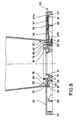
- the total designated 100 device has a first coil receiving device 103 and a second coil receiving device 104.
- the Winding coil 50 has a conical winding core 52 and a first flange 53 and a second Flange 54 on.
- the first flange 53 is at the end the winding core is arranged with a smaller diameter, the second flange 54 at the end of the winding core with larger diameter.
- the winding spool is essentially rotationally symmetrical to that in its Longitudinal axis 56.
- the winding device is, as shown, preferably designed so that the coil longitudinal axis 56 is vertical stands, and the first flange 53 below and the second flange 54 are arranged above.
- the coil receptacle 103 is also substantially is rotationally symmetrical and is around one Axis 106 rotatable.
- the coil receiving device has a circular base plate 108 on which a Support plate 109 arranged with a smaller diameter is.
- On the support plate 109 is a cone 111, which in a correspondingly shaped bore 72 of the Flange 53 of the winding coil 50 engages. Through this Cone becomes the winding spool with respect to the spool receiving means 103 centered.
- a pulley 115 Concentric with the coil receiving device 103 a pulley 115 is arranged, which over a drive belt 117 from a (not explained in detail) Drive device 116 is driven.
- the upper coil receiving device 104 has a plate 120 which attaches to a punch 122 is.
- the plate is rotatable about an axis of rotation 123 mounted, which with the axis 56 of the reel spool and the axis 106 of the lower coil receiving coincides.
- the stamp is as indicated by the arrow 125 is indicated, raised and lowered, for which, not explained in detail Piston-cylinder units 127 and 128 used become.
- the pistons 129, 130 of the piston-cylinder units are via a yoke 131 with the stamp 122nd connected.
- On the plate 120 is one in the direction of the Wikkelspule pointing ring 112 integrally formed, the outer wall inclined to the plate 120, wherein the angle of the Konizticianswinkel the reel spool 50 corresponds.
- On second ring 113 is on the outer periphery of the plate 120th molded and also points down to the Wikkelspule to.
- the winding device further comprises a laying device 140 provided with a Verlegerolle 142 is, over which the wire or the cable D for Winding coil is guided.
- the laying roller 142 is as indicated by the double arrow 143, in one direction can be raised and lowered parallel to the winding spool axis 56.
- the laying device has to a parallel extending to the longitudinal axis of the winding spool threaded spindle 144, which via a drive device 145 is rotatable in both directions.
- the direction of rotation of the laying device is the laying roller raised, i. in the direction of the drive device 145 moves, or lowered again.
- the function of the winding device is by a Controlled control device (not shown).
- the Controller picks up signals from sensors which indicate the angular velocity of the coil, and signals indicating the respective position of the laying roller 142 show.
- the drive device 116 and the drive device 145 controlled so that during the winding process on the spool 50 results in the desired winding pattern.
- the punch 122 with the coil receiving 104 lowered until this at the top the coil rests.
- the conical ring 112 centers the upper end of the hub with the larger one Diameter and the ring 113 of the coil receiving supports the flange 54 of the coil.
- the wire end is then at the lower flange 53rd fixed, e.g. by an automatic device and the winding spool rotated to to wind up the wire or the cable. It happens the control of the drive device 116 and the drive device 145 preferably so that a Winding image results, as in EP-B-0 334 211, see There in particular Figs. 1, 2 and 4 and the associated Description, results.
- the upper end of the hub and the flange 54 are through the ring 112 and the ring 113, the on a corresponding projection of the flange 54 supported, held pliers. This will be both the radially inward and the radial outward forces directly from the plate 120 recorded and thus a deformation of the Wikkelkernes and the flange in this area reliably prevented.
- the Wire preferably by an automatic catch and Cutting device caught and cut off and the coil end also preferably automatically fixed to the coil. Subsequently, will taken from the coil and can without further Verpakkungslitis be stacked and transported.
- a first embodiment of the reel spool, as used in the device according to the invention will now be, with reference to Figs. 2 to 7 described.
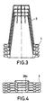
- the coil 1 shown in Fig. 2 consists of a conical hub 2, a first flange 3 and a second flange 4.
- the first flange 3 is removable and arranged at the end 2a of the winding core, whose diameter is smaller.
- the second flange 4 is at the end 2b of the winding core arranged with the larger diameter and is formed integrally with the winding core.
- the coil is generally rotationally symmetrical overall to the running in their longitudinal direction Axis 6.
- Each tab 9 has in its edge region, the End edge of the winding core with the smaller diameter forms, a latching tongue 10 (see also Fig. 7), which is substantially perpendicular to the axis of rotation 6 of the Winding core runs.
- the fixed flange 4 At the second flange end, the fixed flange 4, Reinforcing ribs 14 are provided which the strength increase the flange. Furthermore, a number arranged by bores 16 in the flange, which are vertical run to the axis of rotation 6. The holes can for the use of lifting equipment or else also for the attachment of drainage aids (see Fig. 6) be used.
- the Konizticianswinkel 18 of the cylinder outer shell 2c equal to the Konizticianswinkel 19 of the cylinder inner shell 2d or, otherwise expressed, the shell of the winding core points between the two flanges a constant wall thickness on.
- the first removable flange 3 has, as shown in FIG. 2 and FIG. 7, a conical projection 20 which is rotationally symmetric about an axis 21 which, in the assembled state, with the axis of rotation 6 of Winding core coincides.
- the conical projection 20 faces outward Locking projections 23, the latching surfaces 24th run substantially perpendicular to the cylinder axis 21, this conical projection 20 for mounting the winding core 2 is facing.
- the conical projection 20 is integral with the rotationally symmetrical flange plate 26 connected.
- the winding core 2 side facing away from three concentric ribs arranged, which have an inner Rib ring 28a, a middle rib ring 28b and a form outer rib ring 28c.
- the flange 3 on a flat surface placed and the end 2a of the winding core pressed on the conical projection 20. Because the upper surface 20a of the cone-shaped approach something is conically shaped, the tabs 9 with the locking tongues 10 pushed outward when a pressure on the winding core in the vertical direction on the Flange 3 is applied out. As soon as the winding core 2 pushed down far enough, the tabs spring 9 with the locking tongues 10 elastic back and the locking tongues 10 abut against the locking surfaces 24. In order to the assembly is finished and it can with the winding the coil will be started.
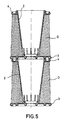
- Figs. 3 and 4 is shown how advantageous the Transport possibilities of Wikkelspule invention are.
- Winding core 2 and removable flange 3 separated from each other and the Winding cores placed so that the end 2b of the Wikkelkerns with the larger diameter down points, so for example on a transport pallet gets up.
- On the winding core can then a large Number of corresponding hubs are stacked wherein the hubs each with the upper end of the Flange 4 stand up to each other. This forms between the nested winding cores small air gap, the adhesion forces between the stacked hubs minimized so that the hubs be easily separated from each other can.
- Fig. 4 is shown how the removable flanges 3 are stacked.
- the inner rib ring 28a designed so that it fits exactly into the conical Opening 20b of the conical projection 20 of the flange fits. This allows the flanges not only It will be stacked up to save space also prevents slippage of the flanges against each other.
- the use of the coils according to the invention So means a reduction of the cargo area 1/17 and a reduction of the load volume to 1/8.
- the loading and unloading is greatly simplified, because to load these 100 coils only one more individual pallet must be moved.
- the design according to the invention is also advantageous when carrying wound coils have to.
- the wound Coils are stacked directly on top of each other. Support it the outer reinforcing ring 28c and the middle Reinforcing ring 28b of the first, removable Flange 3 directly on the second, fixed Flange of the coil from.
- the flange 4 engages in such a way in the recesses 29, that the winding coils against each other be centered and also a slipping the coils against each other is not possible.
- the inventive design can also only partially filled coils transported and stored become.
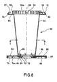
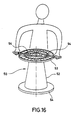
- Fig. 6 shows how the coil directly as a drain device can be used.
- a metallic drainage ring 35 which has a curved metallic surface 36 has, is on the upper flange 4, or partially into the conical cavity of the winding core 2 or inserted and with bolts 37 in the holes 16 secured.
- the wire 38 the is wound on the coil 1, via this drain ring 35th and passed through an eyelet 39. In this way the wire can be pulled off the spool without that additional aids would be required.
- Fig. 7 is shown as winding core 2 and removable Flange 3 are separated from each other can.
- a punch 42 is used as an auxiliary tool, the one from a longer, cylindrical rod 43 with a handle 44, at the bottom End of a cylinder 45 is attached.
- the outer diameter This cylinder is slightly larger than the inner diameter the winding core in the end region 2a.
- the auxiliary tool 42 inserted. As soon as the cylinder 45 the reaches lower end portion 2a, the tabs are 9 with the locking tongues 10 bent outwards and from the locking surfaces 24 separated. Then the Wikkelkern lifted off the flange 3 without further action become.
- the turns Due to the stability of the coils, the turns are especially with double conical winding pattern held so stable on the spool that special Measures, such as setting or strapping the container are not required.
- the total designated 50 winding coil has a conical winding core 52 and a detachable with the winding core 52 connected first flange 53, which is arranged at the end of the winding core, which having the smaller diameter.
- a second Flange 54 is at the end of the winding core with larger Diameter arranged and integral with this educated. Overall, the coil is essentially designed rotationally symmetrical to the longitudinal axis 56.
- the winding core 52 with the molded on it Flange 54 and the removable flange 53 are made made of plastic.
- the flange 54 consists of one of a substantially annular wall part 55, which is in a Plane extending, which is perpendicular to the axis of rotation 56 of the coil is located.
- the wall part 55 is through vertically arranged reinforcing ribs 57 strengthened.
- the wall part 55 is further provided with a cylindrical Ring 58 connected, whose diameter larger than the upper end diameter of the winding core.
- the ring 58 is integral with a plurality of Reinforcing ribs 58 a formed.
- the upper flange 54 is further a number provided by holes 59, which for attachment of hoists or for attaching a drain ring serve.
- a second cylindrical ring 61 Adjacent to this fold 60 is a second cylindrical ring 61 is provided which the flange 54th additionally stiffened and with the reinforcing ribs 57 connected is.
- the locking projections 64 in the embodiment there are eight pieces, are the same distance around the Distributed inner circumference of the hub and are sized so that the distance in the circumferential direction, or the clear width between two adjacent locking projections, is slightly larger than the length of the locking projections self.
- the protrusions are roughly sized that they are 5 to 12 mm from the lower inner edge of the winding core from projecting inwards.
- the first detachable flange 53 has a mounted in the Condition, the winding material facing annular Plate 66 on which an outer, the winding material facing away, ring-like reinforcement 67, the designed in the form of two concentric rings, a second middle reinforcement 68 in the form of a ring and a third, internal annular reinforcement 69. Concentric with the axis of rotation of the Flange (in the mounted state of the rotation axis the coil corresponds), is adjacent to the inner Reinforcing ring 69, a centering ring 70 is provided, the a conical recess 72 has.
- a plurality of equidistantly arranged reinforcing ribs 74 is facing away from the winding material Side of the flange arranged to the Continue to strengthen the flange.
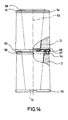
- the diameter of the reinforcing ring 68 is slight larger than the diameter of the reinforcing ring 58 of the second flange 54. Further have the reinforcing ribs 74 in the region of the reinforcing ring 68 incisions 74a (see Fig. 8) on. If the wound coils stacked on each other, as shown in Fig. 14, the reinforcing ring engages 58 of the second flange in these recesses 74 a a, wherein the upper part of the reinforcing ring 58 in Attachment to the reinforcing ring 68 comes. Thereby When stacking the upper coil is exactly in relation to centered lower coil and a slipping of the upper Spool prevented with respect to the lower coil.
- the flange 53 On the in the assembled state facing the winding material Side, the flange 53 has a substantially annular recess 75 in which a Holding structure 76 is arranged, which with the latching projections 64 of the winding core cooperates.
- the support structure 76 has a concentric to Rotation axis arranged cylindrical ring 78th of which a number of holding projections 79 are radial to project outwards.
- a raiding direction Reinforcing rib 81 arranged, which an additional Connection between the retaining projections and make the cylinder ring 78, and thus the retaining projections stiffen in the axial direction of the reel spool.
- the annular recess 75 is, as in particular can be seen from Fig. 9, by a first wall portion 84 is formed, the front Wall surface, which faces the winding core, in the same Angle to the axis of rotation is inclined, like the Wall of the winding core 52.
- a second wall section 85 closes at, which is arranged perpendicular to the axis of rotation.
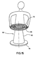
- connection between hub and flange takes place by the winding core so mounted on the flange is (see also Fig. 15) that the locking projections 64 in the region of the gap 83 of the flange lie.
- This allows the winding core so in the flange be introduced, that the lower end of the winding core with the latching projections 64 on the second Wall portion 85 rests, as shown in Fig. 9 is.
- winding core and flange are relatively twisted to each other until the webs 65 of the locking projections 64 on the webs 81 of the retaining projections 79th issue. In this position, one of each engages below Locking projections 64 an associated retaining projection 79, so that an axially secured connection between Winding core and flange consists.
- the locking element 86 consists of a elastic material, such as plastic or metal and has an elongated plate 87, which through two side bars 88 and 89 is guided in the flange. Furthermore is in the middle reinforcing ring 68, a recess 90th provided, through which the plate 87 is guided and the reinforcing ring 67 is radially inward projecting rib 91, which forms a pocket, in the end facing away from the winding core 87a of the plate of the locking element 86 is held. In this Position is the plate 87 substantially parallel to the the winding material facing surface of the flange 53rd and is held in this position.
- the plate is integrally formed with this, a web 92, whose width is slightly less than the width of one Gap 83 between two retaining projections 79 of the flange.
- a wedge-like thickening 93 is formed by which a wedge-shaped gap 94 is formed.
- the front end 87b of the plate has only one small distance to the inner reinforcing ring 69 of the Flange 53 on, so that the locking element 86th through the rib 91, the recess 90 and the rib 69 is held captive on the flange.
- the wedge-like depression 93 has a double function.
- a suitable tool e.g. on Screwdriver is introduced into the wedge gap 94.
- the wedge gap 94 and thus the front end 87b of the Plate 87 are characterized (as shown in FIG Fig. 9) pressed down, whereby the web 92 the Space between the adjacent holding projections releases, and flange and hub twisted against each other can be.
- the Wikkelkern can then without further manual actions from the flange be removed.
- the releasable ones may also be used Flanges 53 of the coil 50 in a similar manner as the flanges 3 (see Fig. 4) stacked to save space become.
- the ring 69 has a series of notches, which are indicated in FIGS. 9 and 10, in which engage the webs 81 when stacking.
- the present invention thus provides a method and a device proposed by the or by which a container can be produced, the from a winding spool with the wound on it Wire or cable consists, and which in particular advantageous to transport and process is.
- the container especially when using a biconical winding construction, high strength has, the transport is readily packaging material possible. As a result, the user falls these containers no more waste.
- Divisible plastic coil can be the plastic coil the user saves space be and save space again to wire or Cable manufacturers are transported back.
Landscapes
- Physics & Mathematics (AREA)
- General Physics & Mathematics (AREA)
- Optics & Photonics (AREA)
- Storage Of Web-Like Or Filamentary Materials (AREA)
- Winding Filamentary Materials (AREA)
- Wire Processing (AREA)
- Shaping Of Tube Ends By Bending Or Straightening (AREA)
- Rigid Containers With Two Or More Constituent Elements (AREA)
- Basic Packing Technique (AREA)
- Winding, Rewinding, Material Storage Devices (AREA)
- Primary Cells (AREA)
Claims (18)
- Procédé pour réaliser un paquet non emballé et capable d'être transporté, avec un matériau allongé à bobiner, ledit procédé comprenant les étapes de procédé suivantes en succession temporelle:assemblage d'un noyau de bobinage qui comprend une âme de bobinage conique et deux brides, dans lesquelles au moins la bride située du côté de l'âme de bobinage qui présente le plus petit diamètre est reliée de façon détachable à l'âme de bobinage;introduction du noyau de bobinage dans un appareil de bobinage;réception du noyau de bobinage dans l'appareil de bobinage au moyen de deux dispositifs de réception de noyau, qui centrent les deux brides et qui supportent les deux surfaces détournées de l'âme de bobinage pour encaisser la pression de bobinage;enroulement du matériau à bobiner sur le noyau de bobinage avec un dispositif de dépose qui est commandé par un dispositif de commande de telle manière qu'il en résulte un motif d'enroulement prédéterminé sur le noyau;fixation de la liaison entre la bride détachable et l'âme de bobinage par au moins un élément de verrouillage, de sorte que la bride détachable ne puisse se détacher de l'âme de bobinage lors de l'enroulement et du transport;terminaison de l'opération d'enroulement et enlèvement du noyau de bobinage hors de l'appareil de bobinage dès qu'on a atteint un degré de remplissage souhaité pour le noyau, et dans lequel antérieurement, simultanément ou ensuite, le matériau à enrouler est coupé et l'extrémité côté bobine du matériau à bobiner est fixée sur le noyau de bobinage.
- Procédé selon la revendication 1, caractérisé en ce que l'un au moins des dispositifs de réception de noyau est relié à un dispositif d'entraínement de telle façon que le noyau de bobinage est tourné par le dispositif de réception de noyau, pour le bobinage du matériau à bobiner.
- Procédé selon la revendication 1, caractérisé en ce que le dispositif de dépose est relié à un dispositif d'entraínement au moyen duquel le dispositif de dépose est déplacé autour du noyau stationnaire pour le bobinage du matériau en forme de bande.
- Procédé selon l'une quelconque des revendications 1 à 3, caractérisé par les étapes de procédé supplémentaires suivantes:positionnement du dispositif de dépose après réception du noyau dans la région de l'extrémité de l'âme de bobinage avec le petit diamètre;bobinage d'une première couche de bobinage avec un nombre de spires prédéterminé et un pas de spires prédéterminé;retour du dispositif de dépose dans cette première position à l'emplacement le plus petit de l'âme de bobinage, et en formant une seconde couche de bobinage avec le même nombre de spires et le même pas de spires;réalisation de couches de bobinage supplémentaires qui présentent respectivement des nombres croissants de spires;le nombre respectif des spires est choisi de manière à ce qu'il en résulte sur le noyau un motif de bobinage dans lequel au moins une partie des couches de bobinage sont inclinées contre l'âme de bobinage, vues en coupe longitudinale du noyau;on poursuit ces opérations d'enroulement avec un nombre de spires croissant, jusqu'à atteindre un nombre final de spires pour lequel la couche de bobinage atteint la seconde extrémité de l'âme de bobinage avec le plus grand diamètre;on poursuit l'opération d'enroulement en appliquant d'autres couches de bobinage dont les nombres de spires sont soit égaux soit décroissants par rapport à ce nombre final de spires.
- Procédé selon la revendication 4, caractérisé en ce que l'accroissement des nombres de spires des couches de bobinage successives est choisi de telle sorte qu'après application d'un certain nombre de couches de bobinage et avant d'avoir atteint ce nombre final de spires, la distance entre au moins quelques-unes de ces couches de bobinage individuelles et l'axe de rotation du noyau de bobinage, dans la région de la bride agencée à l'extrémité de l'âme de bobinage qui présente le petit diamètre, atteint son maximum.
- Dispositif pour bobiner un matériau de bobinage allongé sur un noyau de bobinage pour réaliser un paquet non emballé et capable d'être transporté, et en particulier pour mettre en oeuvre le procédé selon l'une quelconque des revendications 1 à 5, comprenant:caractérisé en ce que:deux dispositifs de réception de noyau qui reçoivent et centrent les noyaux dans leur zone terminale, lesdits dispositifs de réception de noyau étant agencés de telle manière que l'axe longitudinal d'un noyau de bobinage reçu par ceux-ci est dirigé sensiblement verticalementun dispositif de dépose, au moyen duquel le matériau de bobinage allongé est amené au noyau, ledit dispositif de dépose étant mobile parallèlement à l'axe longitudinal du noyau;un dispositif d'entraínement qui est relié au dispositif de réception de noyau ou au dispositif de dépose de telle façon que le noyau ou le dispositif de dépose tourne autour de l'axe longitudinal du noyau;un dispositif de levage au moyen duquel l'un au moins des dispositifs de réception de noyau peut être déplacé par rapport au noyau, de sorte que le noyau de bobinage peut être introduit dans le dispositif de bobinage, ou enlevé de celui-ci;un dispositif de commande au moyen duquel le déplacement de rotation du noyau de bobinage, ou du dispositif de dépose, et le déplacement du dispositif de dépose parallèlement au noyau, sont commandés de telle façon qu'il apparaít sur le noyau un motif de bobinage prédéterminé;les dispositifs de réception de noyau sont conçus de manière à recevoir un noyau de bobinage en matière plastique avec une âme conique, dans lequel une brideau moins du noyau de bobinage est reliée de façon détachable à l'âme;le premier dispositif de réception de noyau (103), ou dispositif inférieur, comporte une plaque (108, 109), au moyen duquel la première bride (53) ou bride inférieure du noyau de bobinage est directement soutenue;sur cette plaque de soutien est agencé un cône (111) qui s'engage dans un perçage de conception correspondante (72) de la bride (53) pour le centrage du noyau de bobinage;le second dispositif de réception de noyau (104) ou dispositif supérieur, comporte une plaque (120) sensiblement de forme circulaire, laquelle est réalisée de telle manière qu'une bride supérieure du noyau de bobinage est soutenue par le dispositif de réception de noyau; etcette plaque (120) comporte un premier dispositif de centrage (112), en saillie vers le noyau de bobinage, qui s'applique contre la paroi intérieure de l'âme de bobinage dans son extrémité supérieure,un élément de verrouillage (86) est prévu pour la fixation de la jonction entre la première bride détachable et l'âme de bobinage qui assure la jonction entre ladite bride et ladite âme de bobinage et qui bouge dans une direction axiale du bobinage entre une position verrouillée et une position déverrouillée,et ledit élément de verrouillage appuie sur ladite plaque (109) du dispositif inférieur de réception de noyau (103) de telle sorte qu'on empêche un mouvement axiale dans une position déverrouillée.
- Dispositif selon la revendication 6, caractérisé en ce que ce dispositif de centrage (112) est réalisé sous forme d'une nervure qui est fixée sur cette plaque (120).
- Dispositif selon la revendication 7, caractérisé en ce que, sur la plaque (120) est agencée une seconde nervure (111), de façon concentrique à cette nervure de centrage (112), au moyen de laquelle cette bride supérieure (54) du noyau de bobinage est supportée.
- Dispositif selon l'une des revendications 6 à 8, caractérisé en ce que ledit dispositif de levage est relié à la plaque (120) du dispositif supérieur de réception de noyau.
- Noyau de bobinage pour réaliser un paquet non emballé et capable d'être transporté, et en particulier destiné à être employé dans le procédé selon la revendication 1, ou avec le dispositif selon la revendication 6, dans lequel le noyau de bobinage prévu pour recevoir un matériau de bobinage allongé à bobiner, et en particulier un matériau à bobiner qui contient du métal, tel que des fils, des torons, des torons enrobés de matière plastique, etc., comprenant:caractérisé en ce queune âme de bobinage conique creuse, sensiblement à symétrie de révolution, qui présente une première extrémité de petit diamètre et une seconde extrémité de grand diamètre, la cavité (2e) de l'âme (2) étant réalisée de sous forme conique, et l'angle de conicité (18) de l'enveloppe extérieure (2c) et l'angle de conicité (19) de l'enveloppe intérieure (2d) sont sensiblement coïncidents, et la cavité (2e) est ouverte par rapport à la seconde extrémité de grand diamètre;une bride agencée à la seconde extrémité de l'âme de bobinage de grand diamètre;
le noyau de bobinage comporte une première et une seconde bride, ladite première bride (3) étant fixée de façon détachable sur la première extrémité de l'âme de bobinage (2a) de petit diamètre (2a), et
des moyens de liaison (9, 10, 23) sont prévus pour relier ladite première bride (3) et l'âme de bobinage (2), et ils sont conçus de manière que la bride peut se détacher pendant l'enroulement, mais ne peut pas se détacher de l'âme de bobinage pendant le transport,
de sorte que lesdits moyens de liaison comportent des saillies d'enclenchement (64) écartées les unes des autres et faisant saillie radialement vers l'intérieur, lesquelles coopèrent, dans l'état monté, avec des saillies d'arrêt (79) conçues de façon correspondante et s'étendant également en direction radiale, dans la bride amovible (53), de sorte que la bride amovible et l'âme de bobinage sont tenus l'un par rapport à l'autre en direction axiale, c'est-à-dire dans la direction longitudinale de l'axe de rotation (56) du noyau de bobinage (50),
au moins un élément de verrouillage (86) est prévu consistant d'un matériau élastique comme plastique ou métal, qui présente une plaque allongée s'étendant à une direction radiale, qui est guidée par d'eux portants latéraux (88 ; 89) dans la bride et qui assure la jonction entre la bride détachable et l'âme de bobinage,
les saillies d'arrêt (79) présentent dans la direction périphérique.de la bride (53) une distance qui est supérieure à la longueur de ces saillies d'enclenchement (64), et en ce que des saillies d'arrêt (79) et des saillies d'enclenchement (64) sont amenées en engagement mutuel de telle manière que l'âme de bobinage (52) avec les saillies d'enclenchement est d'abord mise en place entre ces saillies d'arrêt, et en ce que la bride et l'âme de bobinage sont alors tournées l'une par rapport à l'autre d'un angle prédéterminé, de sorte que ces saillies d'arrêt et ces saillies d'enclenchement viennent en engagement mutuel et
ledit au moins un élément de verrouillage (86) s'engage dans l'intervalle entre lesdites saillies d'arrêt (79), ferme cet intervalle et par cela bloque un mouvement relatif de l'âme de bobinage (52) et de la bride amovible (53). - Noyau de bobinage selon la revendication 10, caractérisé en ce que l'âme de bobinage (2; 52) est réalisée en matière plastique.
- Noyau de bobinage selon l'une ou l'autre des revendications 10 ou 11, caractérisé en ce que la bride amovible (3 ; 53) est réalisée en matière plastique.
- Noyau de bobinage selon l'une au moins des revendications précédentes, caractérisé en ce que la bobine comporte une seconde bride (4; 54) qui présente un diamètre important à l'extrémité de l'âme de bobinage, ladite bride étant fermement reliée à l'âme de bobinage (2), et étant de préférence réalisée d'une seule pièce avec l'âme de bobinage (2).
- Noyau de bobinage selon la revendication 10, caractérisé en ce que ledit élément de verrouillage (86) est réalisé sous forme d'un élément déformable de façon élastique, lequel est retenu dans la bride amovible, et est déformable de façon élastique lors de l'assemblage de l'âme de bobinage (52) et de la bride (53) ou depuis l'extérieur au moyen d'un outil, de telle manière qu'il libère dans l'état déformé l'intervalle entre ces saillies d'arrêt, de sorte qu'un mouvement de rotation entre 1 âme de bobinage et ladite bride amovible est possible, et en ce qu'il retourne après cette déformation jusque dans sa position de départ, dans laquelle on empêche un mouvement de rotation entre l'âme de bobinage et la bride amovible.
- Noyau de bobinage selon l'une ou l'autre des revendications 10 et 14, caractérisé en ce que l'élément de verrouillage comporte un épaississement (93), lequel est conçu de telle manière que l'élément de verrouillage ne parvient pas dans une position dans laquelle la rotation de l'âme de bobinage est libérée, lorsque le noyau de bobinage (50) avec la bride amovible (53) dépassent sur une surface plane, ou sur une surface de réalisation correspondante.
- Noyau de bobinage selon l'une au moins des revendications 10 à 15, caractérisé en ce que la bride amovible (3 ; 53) comporte une surface de bride sensiblement en forme de disque circulaire, et en ce que des nervures de renfort s'étendant en direction périphérique et en direction radiale sont prévues sur le côté détourné de l'âme de bobinage dans cette partie en forme de disque.
- Noyau de bobinage selon l'une au moins des revendications 10 à 16, caractérisé en ce que des nervures de renfort s'étendant en direction périphérique et en direction radiale sont prévues sur la bride fixe (4; 54).
- Noyau de bobinage selon les revendications 16 et 17, caractérisé en ce que les nervures de renfort de la bride amovible (3; 53) et de la bride supérieure (4; 54) sont conçues de telle manière que, lorsqu'on empile les uns sur les autres plusieurs noyaux montés et éventuellement remplis, les nervures de renfort de la bride supérieure et de la bride inférieure s'engagent de telle manière les unes dans les autres qu'on réalise une liaison à coopération de formes qui empêche un glissement des brides l'une par rapport à l'autre.
Applications Claiming Priority (1)
| Application Number | Priority Date | Filing Date | Title |
|---|---|---|---|
| PCT/EP1992/002804 WO1994013569A1 (fr) | 1992-12-04 | 1992-12-04 | Procede et dispositif de fabrication d'un emballage de materiaux allonges a enrouler |
Publications (3)
| Publication Number | Publication Date |
|---|---|
| EP0672016A1 EP0672016A1 (fr) | 1995-09-20 |
| EP0672016B1 EP0672016B1 (fr) | 1997-08-06 |
| EP0672016B2 true EP0672016B2 (fr) | 2004-03-03 |
Family
ID=8165696
Family Applications (2)
| Application Number | Title | Priority Date | Filing Date |
|---|---|---|---|
| EP92924663A Expired - Lifetime EP0672016B2 (fr) | 1992-12-04 | 1992-12-04 | Procede et dispositif de fabrication d'un emballage de materiaux allonges a enrouler |
| EP94902671A Expired - Lifetime EP0628013B1 (fr) | 1992-12-04 | 1993-12-03 | Bobine pour la reception de matieres allongees a enrouler |
Family Applications After (1)
| Application Number | Title | Priority Date | Filing Date |
|---|---|---|---|
| EP94902671A Expired - Lifetime EP0628013B1 (fr) | 1992-12-04 | 1993-12-03 | Bobine pour la reception de matieres allongees a enrouler |
Country Status (11)
| Country | Link |
|---|---|
| US (1) | US5593108A (fr) |
| EP (2) | EP0672016B2 (fr) |
| JP (1) | JP3241044B2 (fr) |
| CN (1) | CN1066123C (fr) |
| AT (2) | ATE156456T1 (fr) |
| BR (1) | BR9207179A (fr) |
| CA (1) | CA2150958C (fr) |
| DE (4) | DE59208786D1 (fr) |
| ES (2) | ES2107555T5 (fr) |
| FI (1) | FI105090B (fr) |
| WO (2) | WO1994013569A1 (fr) |
Cited By (2)
| Publication number | Priority date | Publication date | Assignee | Title |
|---|---|---|---|---|
| DE102005011022A1 (de) * | 2005-03-10 | 2006-09-14 | Häfner & Krullmann Gmbh | Verfahren zum Bewickeln einer Spule mit strangförmigem Wickelgut |
| DE102012024450A1 (de) | 2012-12-13 | 2014-06-18 | Maschinenfabrik Niehoff Gmbh & Co. Kg | Wickelspule für ein Gebinde, sowie Verfahren zu dessen Herstellung und Abwicklung |
Families Citing this family (33)
| Publication number | Priority date | Publication date | Assignee | Title |
|---|---|---|---|---|
| JP2808440B2 (ja) * | 1996-11-26 | 1998-10-08 | ゴールド工業株式会社 | 物流用リール |
| US6045087A (en) * | 1996-08-26 | 2000-04-04 | Vislocky; Mark | Spool assembly for snap fit of flanges and spindle having guiding members for aligning with the flanges spindle |
| DE19706832C1 (de) * | 1997-02-21 | 1998-07-09 | Haefner & Krullmann Gmbh | Wickelspule |
| US6062506A (en) * | 1997-11-14 | 2000-05-16 | Maschinenfabrik Niehoff Gmbh & Co. Kg | Process and device for producing a package of elongated winding material |
| DE29822211U1 (de) * | 1998-12-14 | 1999-02-04 | Häfner & Krullmann GmbH, 33818 Leopoldshöhe | Wickelspule |
| DE10016518B4 (de) * | 2000-04-03 | 2009-07-02 | Maschinenfabrik Niehoff Gmbh & Co Kg | Verfahren und Vorrichtung zur Herstellung eines isolierten Kabels |
| JP4580073B2 (ja) * | 2000-07-24 | 2010-11-10 | 岐阜プラスチック工業株式会社 | ケーブル巻きドラム用鍔部の構造 |
| US20040211851A1 (en) * | 2003-04-24 | 2004-10-28 | Lincoln Global , Inc. | Welding wire payout drum |
| WO2005070802A1 (fr) * | 2004-01-26 | 2005-08-04 | Maschinenfabrik Niehoff Gmbh & Co. Kg | Enrouleur pour un emballage, et procede de production associe et deroulage |
| ES2264330B1 (es) * | 2004-06-18 | 2007-11-16 | Angel Lorenzo Barroso | Carrete desmontable con dispositivo de bloqueo. |
| DE102004048269A1 (de) * | 2004-10-04 | 2006-04-06 | Maschinenfabrik Niehoff Gmbh & Co Kg | Wickeleinsatz für ein transportfähiges Kleingebinde, Verfahren und Vorrichtung zur Herstellung eines transportfähigen Kleingebindes, transportfähiges Kleingebinde |
| DE102005010709B4 (de) * | 2005-03-09 | 2007-03-29 | Häfner & Krullmann Gmbh | Spule zur Aufnahme von aufwickelbarem Strangmaterial |
| DE102005010708B4 (de) * | 2005-03-09 | 2007-03-15 | Häfner & Krullmann Gmbh | Verbindungssystem |
| DE102005010710B4 (de) * | 2005-03-09 | 2007-08-09 | Häfner & Krullmann Gmbh | Spule zur Aufnahme von aufwickelbarem Stranggut |
| US20090218436A1 (en) * | 2008-02-28 | 2009-09-03 | Andre Charron | Spool |
| US20100258663A1 (en) * | 2009-04-14 | 2010-10-14 | Jamie Limber | Lighting string storage device |
| FI123382B (fi) | 2010-10-11 | 2013-03-28 | Heinolan Sahakoneet Oy | Laitteisto pelkan työstämiseksi ja jakamiseksi puukappaleisiin |
| DE102011009091A1 (de) * | 2011-01-21 | 2012-07-26 | Maschinenfabrik Niehoff Gmbh & Co Kg | Spule zur Aufnahme von Wickelgut sowie Spulenteilesystem |
| US8272591B2 (en) | 2011-01-24 | 2012-09-25 | Sonoco, Inc. | Breakdown spool |
| US20130239519A1 (en) * | 2012-03-16 | 2013-09-19 | Thomas Orsini | Easily removable selvage device |
| CN103420218A (zh) * | 2013-07-16 | 2013-12-04 | 衢州邦鼎键合线制造有限公司 | 一种键合线的绕线方法 |
| KR101528062B1 (ko) * | 2013-12-09 | 2015-06-10 | 이시우 | 심부시추용 전기다운홀모터에 전력을 공급하는 전력케이블 설치시스템 및 방법 |
| CN104894902B (zh) * | 2015-07-03 | 2017-03-15 | 淮安市楚州区大伟常发农机专业合作社 | 全自动草绳机 |
| CN107215713A (zh) * | 2017-06-22 | 2017-09-29 | 黄永怀 | 一种尼龙线的收卷装置 |
| US10538410B2 (en) * | 2018-03-06 | 2020-01-21 | Reelex Packaging Solutions, Inc. | Coiled wire winding spool with self-centering removable endform assembly |
| CN108394761A (zh) * | 2018-03-26 | 2018-08-14 | 江苏山峰铜业科技有限公司 | 一种无氧铜丝绕线设备 |
| CN110887728B (zh) * | 2019-12-09 | 2023-06-02 | 中国航空综合技术研究所 | 用于绑扎绳拉伸试验的固定装置 |
| CN110861981B (zh) * | 2020-01-19 | 2020-06-16 | 胜利油田新大管业科技发展有限责任公司 | 卧式组合收放卷设备及其使用方法 |
| CN111362063A (zh) * | 2020-04-07 | 2020-07-03 | 济南玖源机电科技有限公司 | 一种自动化卧式绕线机 |
| CN111824863B (zh) * | 2020-08-19 | 2025-03-11 | 成都五一科技有限公司 | 卷绕轮及具有该卷绕轮的卷绕机 |
| CN112061877B (zh) * | 2020-09-10 | 2022-04-26 | 中车株洲电力机车研究所有限公司 | 风力发电机组动力电缆绕线、下线装置及绕线、下线方法 |
| CN112110284A (zh) * | 2020-10-17 | 2020-12-22 | 国网河南省电力公司光山县供电公司 | 一种电力工程用电缆收卷装置 |
| CN113562536B (zh) * | 2021-09-18 | 2021-12-03 | 江苏领盛信息科技有限公司 | 一种地铁广播系统用线缆整理设备 |
Citations (12)
| Publication number | Priority date | Publication date | Assignee | Title |
|---|---|---|---|---|
| US3552677A (en) † | 1968-12-16 | 1971-01-05 | Plastics Inc | Knockdown spool |
| US3827651A (en) † | 1972-06-12 | 1974-08-06 | Evans G Corp | Knock-down shipping cable reel |
| US3940085A (en) † | 1975-02-07 | 1976-02-24 | Campbell Kenneth E | Collapsible reel |
| DE7908353U1 (de) † | 1979-03-24 | 1979-08-09 | Astro Plastik Fritz Funke Gmbh & Co Kg, 5768 Sundern | Spulenbehaelter |
| DE8204141U1 (de) † | 1982-02-15 | 1982-08-19 | Henrich, Werner, 6349 Hörbach | Spule als traeger fuer fadenfoermige gueter, wie draehte, litzen, seile, glasfasern oder dergleichen |
| DE3137990A1 (de) † | 1981-09-24 | 1983-04-21 | Maschinenfabrik Niehoff Kg, 8540 Schwabach | Verfahren und vorrichtung zum kontinuierlichen spulenwechsel an ein- oder mehrgaengigen, kontinuierlich arbeitenden wickelstationen fuer strangfoermiges gut, insbesondere fuer draht |
| JPS5930438A (ja) † | 1982-08-10 | 1984-02-18 | Shinko Kosen Kogyo Kk | 撚線の製造方法 |
| US4462555A (en) † | 1982-12-13 | 1984-07-31 | At&T Technologies, Inc. | Split reel with quick-release flange |
| DE8525459U1 (de) † | 1985-09-06 | 1985-10-24 | Häfner & Krullmann GmbH, 4817 Leopoldshöhe | Aufnahmespule für insbesondere bandförmiges Wickelgut |
| DE3543118A1 (de) † | 1985-12-06 | 1987-06-11 | Wolff Walsrode Ag | Siegelbare mehrschichtfolien |
| EP0411978A1 (fr) † | 1989-08-02 | 1991-02-06 | POSSO, Patrick | Bobine pour l'enroulement d'une bande et plus particulièrement d'une bande à alvéoles contenant des composants électroniques |
| DE4010005C2 (fr) † | 1990-03-26 | 1993-09-16 | Siemens Ag, 1000 Berlin Und 8000 Muenchen, De |
Family Cites Families (17)
| Publication number | Priority date | Publication date | Assignee | Title |
|---|---|---|---|---|
| FR963686A (fr) * | 1950-07-18 | |||
| US3124923A (en) * | 1961-08-02 | 1964-03-17 | Method and apparatus for twisting a plurality of strands | |
| US3635421A (en) * | 1969-11-20 | 1972-01-18 | Western Electric Co | Spool assemblies |
| US3822841A (en) | 1972-11-24 | 1974-07-09 | K Campbell | Knockdown reel |
| JPS5728304Y2 (fr) * | 1977-05-20 | 1982-06-21 | ||
| DE2822213A1 (de) * | 1978-05-22 | 1979-11-29 | Theysohn Friedrich Fa | Zerlegbare trommel fuer kabel oder leitungen |
| JPS5734616Y2 (fr) * | 1978-11-22 | 1982-07-30 | ||
| DE7935978U1 (de) * | 1979-12-21 | 1980-05-14 | Franz Filthaut Kg, 5750 Menden | Spule zum aufwickeln von garnen o.dgl. |
| US4377264A (en) * | 1981-06-22 | 1983-03-22 | Wyrepak Industries, Inc. | Spool handling device |
| US4471919A (en) * | 1982-09-13 | 1984-09-18 | Crellin, Inc. | Utility reel |
| DE3712680C1 (en) * | 1987-04-14 | 1988-10-20 | Stewing Kunststoffbetr Gmbh | Cable drum which can be dismantled |
| US4903913A (en) * | 1987-08-17 | 1990-02-27 | Advanced Products Incorporated | Knock-down spool assembly |
| DE3844964C2 (de) * | 1988-03-22 | 1997-02-13 | Niehoff Kg Maschf | Verfahren zum Abzug eines Gebindes aus strangförmigem Gut |
| US5255863A (en) * | 1988-03-22 | 1993-10-26 | Maschinenfabrik Niehoff Gmbh & Co. Kg | Method for producing a coil |
| US5014923A (en) * | 1990-04-09 | 1991-05-14 | Eastman Kodak Company | Web-spool for a cartridge |
| ES2082121T3 (es) * | 1991-03-22 | 1996-03-16 | Kbe Elektrotechnik Gmbh | Sistema de envio para un cable electrico que forma un cuerpo arrollado en forma de cono truncado hueco. |
| DE59200950D1 (de) * | 1991-06-26 | 1995-01-26 | Stewing Kunststoff | Kabeltrommel. |
-
1992
- 1992-12-04 DE DE59208786T patent/DE59208786D1/de not_active Expired - Lifetime
- 1992-12-04 AT AT92924663T patent/ATE156456T1/de active
- 1992-12-04 CA CA002150958A patent/CA2150958C/fr not_active Expired - Lifetime
- 1992-12-04 EP EP92924663A patent/EP0672016B2/fr not_active Expired - Lifetime
- 1992-12-04 DE DE9218853U patent/DE9218853U1/de not_active Expired - Lifetime
- 1992-12-04 BR BR9207179A patent/BR9207179A/pt not_active IP Right Cessation
- 1992-12-04 WO PCT/EP1992/002804 patent/WO1994013569A1/fr not_active Ceased
- 1992-12-04 JP JP51369794A patent/JP3241044B2/ja not_active Expired - Fee Related
- 1992-12-04 ES ES92924663T patent/ES2107555T5/es not_active Expired - Lifetime
-
1993
- 1993-12-03 EP EP94902671A patent/EP0628013B1/fr not_active Expired - Lifetime
- 1993-12-03 DE DE9320412U patent/DE9320412U1/de not_active Expired - Lifetime
- 1993-12-03 DE DE59309477T patent/DE59309477D1/de not_active Expired - Lifetime
- 1993-12-03 WO PCT/EP1993/003404 patent/WO1994013570A1/fr not_active Ceased
- 1993-12-03 AT AT94902671T patent/ATE178024T1/de active
- 1993-12-03 ES ES94902671T patent/ES2133530T3/es not_active Expired - Lifetime
- 1993-12-03 US US08/284,450 patent/US5593108A/en not_active Expired - Lifetime
- 1993-12-04 CN CN93121150A patent/CN1066123C/zh not_active Expired - Lifetime
-
1995
- 1995-06-02 FI FI952702A patent/FI105090B/fi not_active IP Right Cessation
Patent Citations (12)
| Publication number | Priority date | Publication date | Assignee | Title |
|---|---|---|---|---|
| US3552677A (en) † | 1968-12-16 | 1971-01-05 | Plastics Inc | Knockdown spool |
| US3827651A (en) † | 1972-06-12 | 1974-08-06 | Evans G Corp | Knock-down shipping cable reel |
| US3940085A (en) † | 1975-02-07 | 1976-02-24 | Campbell Kenneth E | Collapsible reel |
| DE7908353U1 (de) † | 1979-03-24 | 1979-08-09 | Astro Plastik Fritz Funke Gmbh & Co Kg, 5768 Sundern | Spulenbehaelter |
| DE3137990A1 (de) † | 1981-09-24 | 1983-04-21 | Maschinenfabrik Niehoff Kg, 8540 Schwabach | Verfahren und vorrichtung zum kontinuierlichen spulenwechsel an ein- oder mehrgaengigen, kontinuierlich arbeitenden wickelstationen fuer strangfoermiges gut, insbesondere fuer draht |
| DE8204141U1 (de) † | 1982-02-15 | 1982-08-19 | Henrich, Werner, 6349 Hörbach | Spule als traeger fuer fadenfoermige gueter, wie draehte, litzen, seile, glasfasern oder dergleichen |
| JPS5930438A (ja) † | 1982-08-10 | 1984-02-18 | Shinko Kosen Kogyo Kk | 撚線の製造方法 |
| US4462555A (en) † | 1982-12-13 | 1984-07-31 | At&T Technologies, Inc. | Split reel with quick-release flange |
| DE8525459U1 (de) † | 1985-09-06 | 1985-10-24 | Häfner & Krullmann GmbH, 4817 Leopoldshöhe | Aufnahmespule für insbesondere bandförmiges Wickelgut |
| DE3543118A1 (de) † | 1985-12-06 | 1987-06-11 | Wolff Walsrode Ag | Siegelbare mehrschichtfolien |
| EP0411978A1 (fr) † | 1989-08-02 | 1991-02-06 | POSSO, Patrick | Bobine pour l'enroulement d'une bande et plus particulièrement d'une bande à alvéoles contenant des composants électroniques |
| DE4010005C2 (fr) † | 1990-03-26 | 1993-09-16 | Siemens Ag, 1000 Berlin Und 8000 Muenchen, De |
Cited By (2)
| Publication number | Priority date | Publication date | Assignee | Title |
|---|---|---|---|---|
| DE102005011022A1 (de) * | 2005-03-10 | 2006-09-14 | Häfner & Krullmann Gmbh | Verfahren zum Bewickeln einer Spule mit strangförmigem Wickelgut |
| DE102012024450A1 (de) | 2012-12-13 | 2014-06-18 | Maschinenfabrik Niehoff Gmbh & Co. Kg | Wickelspule für ein Gebinde, sowie Verfahren zu dessen Herstellung und Abwicklung |
Also Published As
| Publication number | Publication date |
|---|---|
| CA2150958A1 (fr) | 1994-06-23 |
| CN1091718A (zh) | 1994-09-07 |
| FI105090B (fi) | 2000-06-15 |
| WO1994013569A1 (fr) | 1994-06-23 |
| WO1994013570A1 (fr) | 1994-06-23 |
| DE9320412U1 (de) | 1994-06-23 |
| EP0628013B1 (fr) | 1999-03-24 |
| EP0672016B1 (fr) | 1997-08-06 |
| EP0672016A1 (fr) | 1995-09-20 |
| JPH08504725A (ja) | 1996-05-21 |
| CA2150958C (fr) | 2005-11-22 |
| JP3241044B2 (ja) | 2001-12-25 |
| FI952702A7 (fi) | 1995-06-02 |
| ES2133530T3 (es) | 1999-09-16 |
| BR9207179A (pt) | 1995-12-12 |
| ES2107555T5 (es) | 2004-11-01 |
| ATE156456T1 (de) | 1997-08-15 |
| DE59208786D1 (de) | 1997-09-11 |
| EP0628013A1 (fr) | 1994-12-14 |
| ES2107555T3 (es) | 1997-12-01 |
| CN1066123C (zh) | 2001-05-23 |
| DE9218853U1 (de) | 1995-11-02 |
| US5593108A (en) | 1997-01-14 |
| DE59309477D1 (de) | 1999-04-29 |
| ATE178024T1 (de) | 1999-04-15 |
| FI952702A0 (fi) | 1995-06-02 |
Similar Documents
| Publication | Publication Date | Title |
|---|---|---|
| EP0672016B2 (fr) | Procede et dispositif de fabrication d'un emballage de materiaux allonges a enrouler | |
| DE3809635C3 (de) | Verfahren und Vorrichtung zur Herstellung eines spulenlosen Gebindes sowie ein mit dem Verfahren hergestelltes Gebinde | |
| DE4001250A1 (de) | Spule | |
| EP0201794A2 (fr) | Corps de bobine formé de deux composants | |
| EP0504503B1 (fr) | Ensemble de conditionnement pour un rouleaux de câbles électriques en forme de cône tronqué | |
| EP2931638A1 (fr) | Bobine d'enroulement pour un emballage et procédé pour la fabriquer et la dérouler | |
| EP0404043B1 (fr) | Douille réutilisable | |
| DE3703018A1 (de) | Spule zum aufwickeln von langgestreckten, biegsamen guetern, wie zum beispiel von kabeln, leitungen, rohren oder dergleichen | |
| EP0017186B1 (fr) | Bobine démontable pour l'enroulement, en particulier de fils, et procédé pour monter un roule du sur une telle bobine | |
| EP1855975B1 (fr) | Procede d'enroulement d'un materiau filiforme sur une bobine | |
| WO2005070802A1 (fr) | Enrouleur pour un emballage, et procede de production associe et deroulage | |
| WO2021032560A1 (fr) | Utilisation d'une unité d'emballage pour bandes de cerclage | |
| DE9212690U1 (de) | Spule zur Aufnahme von langgestrecktem Wickelgut | |
| DE69803941T2 (de) | Spule zum tragen von glasfasern und verfahren zum kontrollieren der verformungen, die diese spule während des aufwickelns erfährt | |
| DE29621144U1 (de) | Wickelspule | |
| DE29916947U1 (de) | Aus einer Wickelspule und einem Spulenbehälter gebildete Einheit für die Lieferung und Verpackung sowie für den Transport von Wickelgut | |
| DE102016215953A1 (de) | Wickelverfahren und Wickelvorrichtung zum kontinuierlichen Bewickeln eines Kernes | |
| DE2260463C2 (de) | Konische Wickelhülse für Garne und Fäden | |
| DE29806519U1 (de) | Wickelspule | |
| DE9014040U1 (de) | Spulenkörper, insbesondere für Einwegverpackungen | |
| DE7936908U1 (de) | Verpackung fuer Spulen und/oder Drahtgebinde mit konischem Kern | |
| DE3515931A1 (de) | Spule, bestehend aus zwei, durch einen kern miteinander verbundenen flanschen, insbesondere fuer haftstreifen zum anbringen von schutzplanen fuer abzudeckende bereiche von automobil-karosserien beim farbspritzen | |
| DE9109916U1 (de) | Versandsystem | |
| DE102006017348A1 (de) | Spuleneinrichtung insbesondere für einen schmalen Prägefolienstreifen | |
| DE202006006006U1 (de) | Spuleneinrichtung insbesondere für einen schmalen Prägefolienstreifen |
Legal Events
| Date | Code | Title | Description |
|---|---|---|---|
| PUAI | Public reference made under article 153(3) epc to a published international application that has entered the european phase |
Free format text: ORIGINAL CODE: 0009012 |
|
| 17P | Request for examination filed |
Effective date: 19950512 |
|
| AK | Designated contracting states |
Kind code of ref document: A1 Designated state(s): AT BE CH DE DK ES FR GB IT LI LU NL PT SE |
|
| 17Q | First examination report despatched |
Effective date: 19960415 |
|
| GRAG | Despatch of communication of intention to grant |
Free format text: ORIGINAL CODE: EPIDOS AGRA |
|
| GRAH | Despatch of communication of intention to grant a patent |
Free format text: ORIGINAL CODE: EPIDOS IGRA |
|
| GRAH | Despatch of communication of intention to grant a patent |
Free format text: ORIGINAL CODE: EPIDOS IGRA |
|
| GRAA | (expected) grant |
Free format text: ORIGINAL CODE: 0009210 |
|
| AK | Designated contracting states |
Kind code of ref document: B1 Designated state(s): AT BE CH DE DK ES FR GB IT LI LU NL PT SE |
|
| PG25 | Lapsed in a contracting state [announced via postgrant information from national office to epo] |
Ref country code: NL Free format text: LAPSE BECAUSE OF FAILURE TO SUBMIT A TRANSLATION OF THE DESCRIPTION OR TO PAY THE FEE WITHIN THE PRESCRIBED TIME-LIMIT Effective date: 19970806 Ref country code: DK Free format text: LAPSE BECAUSE OF NON-PAYMENT OF DUE FEES Effective date: 19970806 |
|
| REF | Corresponds to: |
Ref document number: 156456 Country of ref document: AT Date of ref document: 19970815 Kind code of ref document: T |
|
| REG | Reference to a national code |
Ref country code: CH Ref legal event code: NV Representative=s name: AMMANN PATENTANWAELTE AG BERN Ref country code: CH Ref legal event code: EP |
|
| GBT | Gb: translation of ep patent filed (gb section 77(6)(a)/1977) |
Effective date: 19970808 |
|
| REF | Corresponds to: |
Ref document number: 59208786 Country of ref document: DE Date of ref document: 19970911 |
|
| PG25 | Lapsed in a contracting state [announced via postgrant information from national office to epo] |
Ref country code: SE Effective date: 19971106 |
|
| ET | Fr: translation filed | ||
| REG | Reference to a national code |
Ref country code: ES Ref legal event code: FG2A Ref document number: 2107555 Country of ref document: ES Kind code of ref document: T3 |
|
| PG25 | Lapsed in a contracting state [announced via postgrant information from national office to epo] |
Ref country code: LU Free format text: LAPSE BECAUSE OF NON-PAYMENT OF DUE FEES Effective date: 19971204 |
|
| NLV1 | Nl: lapsed or annulled due to failure to fulfill the requirements of art. 29p and 29m of the patents act | ||
| REG | Reference to a national code |
Ref country code: PT Ref legal event code: SC4A Free format text: AVAILABILITY OF NATIONAL TRANSLATION Effective date: 19971016 |
|
| PLAV | Examination of admissibility of opposition |
Free format text: ORIGINAL CODE: EPIDOS OPEX |
|
| PLBQ | Unpublished change to opponent data |
Free format text: ORIGINAL CODE: EPIDOS OPPO |
|
| PLBI | Opposition filed |
Free format text: ORIGINAL CODE: 0009260 |
|
| PLBQ | Unpublished change to opponent data |
Free format text: ORIGINAL CODE: EPIDOS OPPO |
|
| PLAV | Examination of admissibility of opposition |
Free format text: ORIGINAL CODE: EPIDOS OPEX |
|
| PLBF | Reply of patent proprietor to notice(s) of opposition |
Free format text: ORIGINAL CODE: EPIDOS OBSO |
|
| PLBI | Opposition filed |
Free format text: ORIGINAL CODE: 0009260 |
|
| 26 | Opposition filed |
Opponent name: FIRMA HAEFNER & KRULLMANN GMBH & CO. KG Effective date: 19980411 |
|
| 26 | Opposition filed |
Opponent name: HENRICH GMBH Effective date: 19980505 Opponent name: FIRMA HAEFNER & KRULLMANN GMBH & CO. KG Effective date: 19980411 |
|
| PLBF | Reply of patent proprietor to notice(s) of opposition |
Free format text: ORIGINAL CODE: EPIDOS OBSO |
|
| PLBF | Reply of patent proprietor to notice(s) of opposition |
Free format text: ORIGINAL CODE: EPIDOS OBSO |
|
| PLAW | Interlocutory decision in opposition |
Free format text: ORIGINAL CODE: EPIDOS IDOP |
|
| APAC | Appeal dossier modified |
Free format text: ORIGINAL CODE: EPIDOS NOAPO |
|
| APAE | Appeal reference modified |
Free format text: ORIGINAL CODE: EPIDOS REFNO |
|
| APAC | Appeal dossier modified |
Free format text: ORIGINAL CODE: EPIDOS NOAPO |
|
| APAE | Appeal reference modified |
Free format text: ORIGINAL CODE: EPIDOS REFNO |
|
| REG | Reference to a national code |
Ref country code: GB Ref legal event code: IF02 |
|
| APAC | Appeal dossier modified |
Free format text: ORIGINAL CODE: EPIDOS NOAPO |
|
| PLAW | Interlocutory decision in opposition |
Free format text: ORIGINAL CODE: EPIDOS IDOP |
|
| PUAH | Patent maintained in amended form |
Free format text: ORIGINAL CODE: 0009272 |
|
| STAA | Information on the status of an ep patent application or granted ep patent |
Free format text: STATUS: PATENT MAINTAINED AS AMENDED |
|
| 27A | Patent maintained in amended form |
Effective date: 20040303 |
|
| AK | Designated contracting states |
Kind code of ref document: B2 Designated state(s): AT BE CH DE DK ES FR GB IT LI LU NL PT SE |
|
| REG | Reference to a national code |
Ref country code: CH Ref legal event code: AEN Free format text: AUFRECHTERHALTUNG DES PATENTES IN GEAENDERTER FORM |
|
| GBTA | Gb: translation of amended ep patent filed (gb section 77(6)(b)/1977) | ||
| REG | Reference to a national code |
Ref country code: ES Ref legal event code: DC2A Date of ref document: 20040524 Kind code of ref document: T5 |
|
| ET3 | Fr: translation filed ** decision concerning opposition | ||
| APAH | Appeal reference modified |
Free format text: ORIGINAL CODE: EPIDOSCREFNO |
|
| PGFP | Annual fee paid to national office [announced via postgrant information from national office to epo] |
Ref country code: AT Payment date: 20101220 Year of fee payment: 19 |
|
| PGFP | Annual fee paid to national office [announced via postgrant information from national office to epo] |
Ref country code: GB Payment date: 20101221 Year of fee payment: 19 |
|
| PGFP | Annual fee paid to national office [announced via postgrant information from national office to epo] |
Ref country code: IT Payment date: 20101229 Year of fee payment: 19 |
|
| PGFP | Annual fee paid to national office [announced via postgrant information from national office to epo] |
Ref country code: CH Payment date: 20111222 Year of fee payment: 20 Ref country code: PT Payment date: 20111123 Year of fee payment: 20 Ref country code: FR Payment date: 20120103 Year of fee payment: 20 Ref country code: ES Payment date: 20111219 Year of fee payment: 20 |
|
| PGFP | Annual fee paid to national office [announced via postgrant information from national office to epo] |
Ref country code: BE Payment date: 20111220 Year of fee payment: 20 |
|
| PGFP | Annual fee paid to national office [announced via postgrant information from national office to epo] |
Ref country code: DE Payment date: 20120222 Year of fee payment: 20 |
|
| REG | Reference to a national code |
Ref country code: DE Ref legal event code: R071 Ref document number: 59208786 Country of ref document: DE |
|
| REG | Reference to a national code |
Ref country code: DE Ref legal event code: R071 Ref document number: 59208786 Country of ref document: DE |
|
| REG | Reference to a national code |
Ref country code: PT Ref legal event code: MM4A Free format text: MAXIMUM VALIDITY LIMIT REACHED Effective date: 20121204 |
|
| REG | Reference to a national code |
Ref country code: CH Ref legal event code: PL |
|
| REG | Reference to a national code |
Ref country code: GB Ref legal event code: PE20 Expiry date: 20121203 |
|
| BE20 | Be: patent expired |
Owner name: MASCHINENFABRIK *NIEHOFF G.M.B.H. & CO. K.G. Effective date: 20121204 |
|
| REG | Reference to a national code |
Ref country code: AT Ref legal event code: MK07 Ref document number: 156456 Country of ref document: AT Kind code of ref document: T Effective date: 20121204 |
|
| PG25 | Lapsed in a contracting state [announced via postgrant information from national office to epo] |
Ref country code: GB Free format text: LAPSE BECAUSE OF EXPIRATION OF PROTECTION Effective date: 20121203 |
|
| PG25 | Lapsed in a contracting state [announced via postgrant information from national office to epo] |
Ref country code: PT Free format text: LAPSE BECAUSE OF EXPIRATION OF PROTECTION Effective date: 20121212 |
|
| REG | Reference to a national code |
Ref country code: ES Ref legal event code: FD2A Effective date: 20130702 |
|
| PG25 | Lapsed in a contracting state [announced via postgrant information from national office to epo] |
Ref country code: ES Free format text: LAPSE BECAUSE OF EXPIRATION OF PROTECTION Effective date: 20121205 |