EP0654611B1 - Ringschraube - Google Patents
Ringschraube Download PDFInfo
- Publication number
- EP0654611B1 EP0654611B1 EP94250242A EP94250242A EP0654611B1 EP 0654611 B1 EP0654611 B1 EP 0654611B1 EP 94250242 A EP94250242 A EP 94250242A EP 94250242 A EP94250242 A EP 94250242A EP 0654611 B1 EP0654611 B1 EP 0654611B1
- Authority
- EP
- European Patent Office
- Prior art keywords
- eyebolt
- eyelet
- anchor bolt
- head
- screwing tool
- Prior art date
- Legal status (The legal status is an assumption and is not a legal conclusion. Google has not performed a legal analysis and makes no representation as to the accuracy of the status listed.)
- Expired - Lifetime
Links
- 230000007704 transition Effects 0.000 claims description 2
- 239000000725 suspension Substances 0.000 claims 1
- 238000004873 anchoring Methods 0.000 description 21
- 238000003780 insertion Methods 0.000 description 2
- 230000037431 insertion Effects 0.000 description 2
- 239000000463 material Substances 0.000 description 2
- 238000005452 bending Methods 0.000 description 1
- 238000010276 construction Methods 0.000 description 1
- 230000007797 corrosion Effects 0.000 description 1
- 238000005260 corrosion Methods 0.000 description 1
- 230000000694 effects Effects 0.000 description 1
- 238000000926 separation method Methods 0.000 description 1
Images


Classifications
-
- F—MECHANICAL ENGINEERING; LIGHTING; HEATING; WEAPONS; BLASTING
- F16—ENGINEERING ELEMENTS AND UNITS; GENERAL MEASURES FOR PRODUCING AND MAINTAINING EFFECTIVE FUNCTIONING OF MACHINES OR INSTALLATIONS; THERMAL INSULATION IN GENERAL
- F16B—DEVICES FOR FASTENING OR SECURING CONSTRUCTIONAL ELEMENTS OR MACHINE PARTS TOGETHER, e.g. NAILS, BOLTS, CIRCLIPS, CLAMPS, CLIPS OR WEDGES; JOINTS OR JOINTING
- F16B45/00—Hooks; Eyes
- F16B45/002—Eyes
-
- F—MECHANICAL ENGINEERING; LIGHTING; HEATING; WEAPONS; BLASTING
- F16—ENGINEERING ELEMENTS AND UNITS; GENERAL MEASURES FOR PRODUCING AND MAINTAINING EFFECTIVE FUNCTIONING OF MACHINES OR INSTALLATIONS; THERMAL INSULATION IN GENERAL
- F16B—DEVICES FOR FASTENING OR SECURING CONSTRUCTIONAL ELEMENTS OR MACHINE PARTS TOGETHER, e.g. NAILS, BOLTS, CIRCLIPS, CLAMPS, CLIPS OR WEDGES; JOINTS OR JOINTING
- F16B45/00—Hooks; Eyes
-
- B—PERFORMING OPERATIONS; TRANSPORTING
- B66—HOISTING; LIFTING; HAULING
- B66C—CRANES; LOAD-ENGAGING ELEMENTS OR DEVICES FOR CRANES, CAPSTANS, WINCHES, OR TACKLES
- B66C1/00—Load-engaging elements or devices attached to lifting or lowering gear of cranes or adapted for connection therewith for transmitting lifting forces to articles or groups of articles
- B66C1/10—Load-engaging elements or devices attached to lifting or lowering gear of cranes or adapted for connection therewith for transmitting lifting forces to articles or groups of articles by mechanical means
- B66C1/62—Load-engaging elements or devices attached to lifting or lowering gear of cranes or adapted for connection therewith for transmitting lifting forces to articles or groups of articles by mechanical means comprising article-engaging members of a shape complementary to that of the articles to be handled
- B66C1/66—Load-engaging elements or devices attached to lifting or lowering gear of cranes or adapted for connection therewith for transmitting lifting forces to articles or groups of articles by mechanical means comprising article-engaging members of a shape complementary to that of the articles to be handled for engaging holes, recesses, or abutments on articles specially provided for facilitating handling thereof
-
- F—MECHANICAL ENGINEERING; LIGHTING; HEATING; WEAPONS; BLASTING
- F16—ENGINEERING ELEMENTS AND UNITS; GENERAL MEASURES FOR PRODUCING AND MAINTAINING EFFECTIVE FUNCTIONING OF MACHINES OR INSTALLATIONS; THERMAL INSULATION IN GENERAL
- F16G—BELTS, CABLES, OR ROPES, PREDOMINANTLY USED FOR DRIVING PURPOSES; CHAINS; FITTINGS PREDOMINANTLY USED THEREFOR
- F16G15/00—Chain couplings, Shackles; Chain joints; Chain links; Chain bushes
- F16G15/08—Swivels
Definitions
- the invention relates to an eyebolt with a for attaching a sling or lashing device Connection eyelet and one for their attachment an object-serving threaded pin that via a holding member on the provided with a hole Supporting the eye base and in the over the holding member a rotary movement can be initiated.
- an eyebolt is the known type above, which is different as well well-known eye bolts according to DIN 580 and DIN 582 with sloping slinging or lashing equipment in Form of chains or ropes on the direction of the initiated Can adjust force.
- the eyebolt is used to attach it to a Objective threaded pin from the lower end formed of a threaded bolt, the upper end is also designed as a threaded pin and at a collar arranged between the two threaded pins which is a contact surface for the holding eyelet forms the opposite side of the eye base.
- the invention has for its object an eyebolt of the kind contemplated to create which is characterized by a particularly simple structure and only two parts that can be plugged together consists.
- This task is carried out with a generic Eyebolt loosened in that the threaded pin Is part of an anchoring screw whose Head a cylindrical section and one yourself adjoining this, the flange forming the retaining member forms, the cylindrical portion of the Head a larger diameter than the threaded pin has and its end facing away from the ring flange in assembled state of the eye bolt one over the perpendicular to the longitudinal axis of the anchoring screw extending underside of the connecting eye protruding Contact surface forms.
- An eyebolt has proven to be particularly advantageous with the connection eyelet one with the head of the Anchoring screw connected to connectable screwing tool is, through the through the eyelet Screw movement can be introduced into the anchoring screw is.
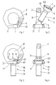
- Figures 1 to 4 show a particularly advantageous Embodiment of an eyebolt.
- Figure 1 is with an insertion opening formed by a bore 1 equipped eyelet 2 of an eyebolt before connecting with an anchoring screw 3 shown.
- the eyelet 2 points in Area of the eye base 21 a circumferential support surface 4, against which a counter surface 5 of a arranged upper end of the anchoring screw 3 Head 6 can create.
- the head 6 has a cylindrical Section 61 and an adjoining one Ring flange 62.
- In the head 6 there is a recess 7 with a hexagon socket, over which with the help of a suitable tool the anchoring screw 3 can be introduced.
- the threaded pin 31 can Anchoring screw 3 when assembling the eyebolt insert it into hole 1 without problems and into the position shown in Figures 3 and 4 convict.
- Protrusions upset that the captivity of the Anchoring screw 3 opposite the eyelet 2 guarantee. Due to the training and location of the head 6 of the anchoring screw 3 in the manner of a countersunk screw head there is not only the freedom of Opening 8 largely preserved, but will be the of the connecting eye 2 forces transmitted to the head 6 also in a convenient place in the anchor screw 3 initiated.
- Figures 3 and 4 show that the lower end of the head 6 has a bearing surface 10 forms that easily over the bottom 11 of the connection eyelet 2 protrudes so that their rotational mobility is guaranteed in the assembled state.
- the Contact surface 10 achieves a support effect, the the bending load of the anchoring screw 3 in greatly reduced.
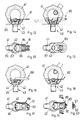
- the eyelet 2 can be used to secure the anchoring screw 3 also one from a transition link formed locking element 12 welded into the terminal eyelet 2 be like this in the embodiment 5 and 6 is shown.
- FIGS. 7 and 8 41 is a connecting eye that again rotatable on the head 42 of an anchoring screw 43 is stored.
- the head 42 of the anchoring screw has an internal hexagon 44, with which is a screw part 45 designed as a cutting edge a screwing tool 46 for transferring a Screw movement from the connecting eye 41 to the anchoring screw 43 is temporarily detachable, so that assembly and disassembly take place in the same way can, like this from one-piece eye bolts is known here.
- the screwing tool 46 consists of an opening 47 formed as a stamped part having bracket, the legs of 48 and 49 over a yoke 50 carrying the screw part 45 together are connected.
- the Opening 47 of the bracket narrower than the width of the Cross section of the connecting eye 41. This means that the screwing tool 46 captive with the connection eyelet 41 is connected. Due to the elasticity of the material used for the screwing tool 46 however, it is possible to widen the opening 47 so far that the screwing tool if necessary from the connection eyelet 41 separately or subsequently with this can be connected.
- Screwing tool 51 a wider than Cut trained screw part 52, which in the Slot 53 of the head 54 of a modified anchor screw 55 takes hold.
- FIGS. 10 and 11 there is a connecting eye 41 an anchoring screw designed as an external hexagon screw 55 captively connected.
- an anchoring screw designed as an external hexagon screw 55 captively connected.
- FIGS. 12 and 13 also show here the legs 84 and 85 are elastic, so that if necessary a separation of the normally captive with the connecting eye 41 connected screwing tool 81 of the connecting eye 41 is possible.
- a Screwing tool 86 which consists of an open oval link and a screw part welded to this oval link 87, is shown in FIGS. 14 and 15, wherein in Figure 14 by dash-dotted Lines the disengaged, i.e. ineffective position of the screwing tool 86 is indicated.
- Screwing tools 88 and 89 are shown for display of a target torque can be used.
- the screwing tool 88 is a stamped one Spring, the ends of which form stops 90 and 91, the user the moment they strike against each other, signal that the anchoring screw 43 sufficiently firm in the for him provided bore is screwed.
- the screwing tool 89 uses a spring bent from round material, the hook-shaped ends in turn as stops 92 and 93 are formed.
- the attacks 90.91 and 92.93 also prevent when loosening the Anchoring screw 43 a plastic deformation the bow-shaped screwing tools 88 and 89 in cases in which it is in the area of the thread to form has come from fretting corrosion.
Description
Claims (17)
- Ringschraube mit einer zum Einhängen eines Anschlag- oder Zurrmittels dienenden Anschlußöse und einem zu ihrer Befestigung an einem Gegenstand dienenden Gewindezapfen, der sich über ein Halteglied am mit einer Bohrung versehenen Osengrund abstützt und in den über das Halteglied eine Drehbewegung einleitbar ist, dadurch gekennzeichnet, daß der Gewindezapfen (31) Teil einer Verankerungsschraube (3) ist, deren Kopf (6) einen zylindrischen Abschnitt (61) und einen sich hieran anschließenden, das Halteglied bildenden Ringflansch (62) formt, wobei der zylindrische Abschnitt (61) des Kopfes (6) einen größeren Durchmesser als der Gewindezapfen (31) hat und sein dem Ringflansch (62) abgewandtes Ende im montierten Zustand der Ringschraube eine über die sich senkrecht zur Längsachse der Verankerungsschraube (3) erstrekkende Unterseite (11) der Anschlußöse (2) vorstehende Auflagefläche (10) bildet.
- Ringschraube nach Anspruch 1, dadurch gekennzeichnet, daß die sich berührenden Flächen (4,5) des Ringflansches (62) des Kopfes (6) der Verankerungsschraube (3) und des Ösengrundes (21) konisch ausgebildet sind.
- Ringschraube nach Anspruch 1 oder 2, dadurch gekennzeichnet, daß die Verankerungsschraube (3) als Innensechskantschraube ausgebildet ist.
- Ringschraube nach einem oder mehreren der Ansprüche 1 bis 3, dadurch gekennzeichnet, daß zur Sicherung der Unverlierbarkeit der Verankerungsschraube (3) in der Bohrung (1) des Ösengrundes (21) mindestens ein die axiale Beweglichkeit der Verankerungsschraube (3) einschränkendes Sperrelement (9;12) dient.
- Ringschraube nach einem oder mehreren der Ansprüche 1 bis 4, dadurch gekennzeichnet, daß die Verankerungsschraube (3) von der der Anschlußöse (2) zugewandten Seite des Ösengrundes (21) in dessen Bohrung (1) einsteckbar ist.
- Ringschraube nach Anspruch 4 oder 5, dadurch gekennzeichnet, daß das Sperrelement (9) von einem einen Anschlag für den Kopf (6) der Verankerungsschraube (3) bildenden Vorsprung der Anschlußöse (2) gebildet wird.
- Ringschraube nach Anspruch 4 oder 5, dadurch gekennzeichnet, daß das Sperrelement (12) von einem in die Öffnung (8) der Anschlußöse (2) eingeschweißten Übergangsglied gebildet wird.
- Ringschraube nach einem oder mehreren der Ansprüche 1 bis 7, dadurch gekennzeichnet, daß mit der Anschlußöse (41) ein mit dem Kopf (42,54,57) der Verankerungsschraube (43,55) kuppelbares Schraubwerkzeug (46,51,80,81,86,88,89) verbunden ist, über das durch die Anschlußöse (41) eine Schraubbewegung in die Verankerungsschraube (43,55) einleitbar ist.
- Ringschraube nach Anspruch 8, dadurch gekennzeichnet, daß das Schraubwerkzeug (46,51,80,81,86,88,89) aus einem zu seiner Halterung an der Anschlußöse (41) dienenden Bügel und einem Schraubteil (45,52,83,87) besteht.
- Ringschraube nach Anspruch 9, dadurch gekennzeichnet, daß der Schraubteil (45,52,83,87) im Bereich des Joches (50,82) des Bügels angeordnet ist.
- Ringschraube nach Anspruch 9 oder 10, dadurch gekennzeichnet, daß die Öffnung (47) des Bügels schmaler als die geringste Breite des Querschnitts der Anschlußöse (41) ist.
- Ringschraube nach einem oder mehreren der Ansprüche 9 bis 11, dadurch gekennzeichnet, daß das Schraubwerkzeug (81,86,89) einen Bügel aufweist, der aus einem gebogenen Drahtabschnitt besteht.
- Ringschraube nach einem oder mehreren der Ansprüche 9 bis 11, dadurch gekennzeichnet, daß das Schraubwerkzeug (46,51, 80,88) als Stanzteil ausgebildet ist.
- Ringschraube nach einem oder mehreren der Ansprüche 9 bis 13, dadurch gekennzeichnet, daß die Schenkel (48,49,84,85) des Bügels zwecks vorübergehender Veränderung der Größe der Öffnung (47) des Bügels deformierbar sind.
- Ringschraube nach einem oder mehreren der Ansprüche 8 bis 14, dadurch gekennzeichnet, daß das Schraubwerkzeug (88,89) als Drehmomentanzeiger ausgebildet ist.
- Ringschraube nach Anspruch 15, dadurch gekennzeichnet, daß das Schraubwerkzeug (88,89) zwei um durch ein Anschlagpaar (90,91;92,93) begrenzte Beträge elastisch auseinanderspreizbare Schenkel aufweist, deren maximale Spreizstellung dem zulässigen Grenzdrehmoment für das Einschrauben der Verankerungsschraube (43) entspricht.
- Ringschraube nach Anspruch 16, dadurch gekennzeichnet, daß die Anschläge (90-93) des Anschlagpaares hakenförmig ausgebildet sind.
Applications Claiming Priority (4)
| Application Number | Priority Date | Filing Date | Title |
|---|---|---|---|
| DE4336780A DE4336780A1 (de) | 1993-10-25 | 1993-10-25 | Ringschraube |
| DE4336780 | 1993-10-25 | ||
| DE4403785 | 1994-02-03 | ||
| DE4403785A DE4403785A1 (de) | 1993-10-25 | 1994-02-03 | Ringschraube |
Publications (2)
| Publication Number | Publication Date |
|---|---|
| EP0654611A1 EP0654611A1 (de) | 1995-05-24 |
| EP0654611B1 true EP0654611B1 (de) | 1998-01-07 |
Family
ID=25930778
Family Applications (1)
| Application Number | Title | Priority Date | Filing Date |
|---|---|---|---|
| EP94250242A Expired - Lifetime EP0654611B1 (de) | 1993-10-25 | 1994-10-07 | Ringschraube |
Country Status (5)
| Country | Link |
|---|---|
| US (1) | US5690457A (de) |
| EP (1) | EP0654611B1 (de) |
| JP (1) | JPH07217630A (de) |
| AT (1) | ATE161926T1 (de) |
| DE (2) | DE4403785A1 (de) |
Cited By (4)
| Publication number | Priority date | Publication date | Assignee | Title |
|---|---|---|---|---|
| WO2001051401A1 (de) | 2000-01-14 | 2001-07-19 | Rud-Kettenfabrik Rieger & Dietz Gmbh U. Co. | Ringmutter |
| DE10164593A1 (de) * | 2001-12-21 | 2003-07-10 | Rud Ketten Rieger & Dietz | Anschlagpunkt |
| CN104907620A (zh) * | 2014-03-13 | 2015-09-16 | (株)成一拉锁 | 在吊环螺栓上形成防分离卡台的装置及方法 |
| CN109795951A (zh) * | 2017-11-17 | 2019-05-24 | 振锋企业股份有限公司 | 吊环螺栓 |
Families Citing this family (42)
| Publication number | Priority date | Publication date | Assignee | Title |
|---|---|---|---|---|
| GB2340533A (en) * | 1998-08-11 | 2000-02-23 | Ykk Europ Ltd | Mounting for a tent |
| ATE305435T1 (de) * | 1999-07-09 | 2005-10-15 | S H B L | Wirbelöse zum heben von lasten |
| ATE345307T1 (de) | 2000-06-15 | 2006-12-15 | S H B L S A | Hebering |
| DE10108867B4 (de) * | 2001-02-15 | 2004-04-29 | Rud-Kettenfabrik Rieger & Dietz Gmbh U. Co. | Anschlussschraube |
| US7783519B2 (en) * | 2002-03-19 | 2010-08-24 | Mjt Holdings, Llc | Fixed eyebolt inventory control method |
| FR2877933B1 (fr) * | 2004-11-17 | 2007-01-12 | Edmond Altabe | Anses de levage tournantes et articulables |
| GB0425384D0 (en) * | 2004-11-18 | 2004-12-22 | Whitaker Peter D | Support device |
| FR2880084B1 (fr) * | 2004-12-23 | 2007-03-02 | Blaise Henrion | Dispositif de fixation du type anneau de levage |
| US7314202B2 (en) * | 2005-02-22 | 2008-01-01 | Everett Franklin C | System for suspending decorative trees |
| US20070201966A1 (en) * | 2006-02-24 | 2007-08-30 | M & W Fastener Co., Ltd. | Flat head screw |
| DE602008005033D1 (de) | 2008-10-30 | 2011-03-31 | Stamperia Carcano Giuseppe S P A | Ösenbefestigungsvorrichtung |
| JP5424839B2 (ja) * | 2009-12-04 | 2014-02-26 | 東京電力株式会社 | ボルト・ナット・ワッシャーの落下防止具 |
| EP2361870A1 (de) | 2010-02-25 | 2011-08-31 | Stamperia Carcano Giuseppe S.p.A. | Ringbolzen mit Abschraubvorrichtung |
| EP2646698B1 (de) | 2010-12-02 | 2015-08-12 | Pewag Austria GmbH | Ringschraube |
| DE202012100764U1 (de) | 2012-03-05 | 2012-04-27 | Thiele Gmbh & Co. Kg | Ringschraube |
| JP6010697B2 (ja) * | 2012-07-31 | 2016-10-19 | ペヴァック・オーストリア・ゲゼルシャフト・ミット・ベシュレンクテル・ハフツングPewag Austria Gmbh | リングナット |
| DE202012103079U1 (de) | 2012-08-15 | 2012-09-03 | J. D. Theile Gmbh & Co. Kg | Anschlagöse |
| CN102923558B (zh) * | 2012-10-31 | 2014-12-31 | 中国航天空气动力技术研究院 | 一种组合式飞机吊耳 |
| CN104343792A (zh) * | 2013-07-24 | 2015-02-11 | 振锋企业股份有限公司 | 吊环螺栓 |
| LU92266B1 (fr) * | 2013-08-13 | 2015-02-16 | Intelprop Sa | Anneau de levage tournant avec outil de verrouillage |
| JP2015045391A (ja) * | 2013-08-29 | 2015-03-12 | 振鋒企業股▲ふん▼有限公司Yoke Industrial Corp. | アイボルト |
| DE102013109975A1 (de) | 2013-09-11 | 2015-03-12 | Yoke Industrial Corp. | Ringbolzen |
| CN104709811A (zh) * | 2013-12-17 | 2015-06-17 | 山东华源莱动内燃机有限公司 | 一种吊环螺母 |
| EP3265419A4 (de) * | 2015-03-05 | 2018-10-17 | The Crosby Group LLC | Rotierende augenschraubenanordnung mit verriegelungsmechanismus |
| US10207902B2 (en) | 2016-09-01 | 2019-02-19 | Mjt Holdings, Llc | Load-mountable lift eye assembly |
| USD803668S1 (en) | 2016-09-01 | 2017-11-28 | Mjt Holdings, Llc | Load-mountable lifting eye |
| DE202016006871U1 (de) | 2016-11-04 | 2016-12-05 | Manfred Redder | Anschlagring mit einer zum Einhängen eines Anschlagmittels oder Zurrmittels dienenden Tragöse. |
| DE202017100479U1 (de) * | 2017-01-30 | 2018-05-03 | Thiele Gmbh & Co. Kg | Ringschraube mit exzentrischem Versatz der Ringöse |
| EP3381860B1 (de) | 2017-03-30 | 2020-01-08 | Rodrigues da Costa, José | Hubring für die beförderung von formen |
| CN107575457A (zh) * | 2017-10-17 | 2018-01-12 | 苏州华丰不锈钢紧固件有限公司 | 一种吊环自密封螺钉 |
| TWI644848B (zh) * | 2017-11-07 | 2018-12-21 | 振鋒企業股份有限公司 | Eyebolt |
| USD840794S1 (en) | 2017-11-27 | 2019-02-19 | Mjt Holdings, Llc | Load-mountable lift eye |
| US10259691B1 (en) | 2017-12-29 | 2019-04-16 | Yoke Industrial Corp. | Hoist ring with engageable retainer |
| DE102018101143A1 (de) * | 2018-01-19 | 2019-07-25 | Yoke Industrial Corp. | Hebering |
| DE202019102552U1 (de) | 2019-05-07 | 2019-05-27 | J. D. Theile Gmbh & Co. Kg | Anschlagpunkt |
| WO2021004894A1 (de) | 2019-07-05 | 2021-01-14 | Westdeutscher Drahtseil-Verkauf Dolezych Gmbh & Co. Kg | Anschlagring |
| DE202020103418U1 (de) | 2020-04-29 | 2021-08-02 | J.D. Theile Gmbh & Co. Kg | Anschlagpunkt |
| USD908477S1 (en) * | 2020-07-01 | 2021-01-26 | Haoliang Liu | Bolt |
| USD922185S1 (en) * | 2020-11-17 | 2021-06-15 | Haoliang Liu | Bolt |
| LU102432B1 (fr) | 2021-01-18 | 2022-07-18 | Codiprolux S A | Point de levage pivotant pour le levage de charges |
| USD974882S1 (en) * | 2021-05-17 | 2023-01-10 | Leon Griffin | Lifting eye |
| JP1711641S (ja) * | 2021-06-29 | 2022-04-04 | 吊り金具 |
Family Cites Families (10)
| Publication number | Priority date | Publication date | Assignee | Title |
|---|---|---|---|---|
| US2748646A (en) * | 1952-09-13 | 1956-06-05 | Harold William | Separable eye for a bolt |
| US4295765A (en) * | 1979-04-23 | 1981-10-20 | Burke Michael R | Tie-down structure |
| DE3009789C2 (de) * | 1980-03-14 | 1982-12-09 | Fa. Friedrich Schroeder, 5982 Neuenrade | Vorrichtung zum Ankuppeln eines Lasthebemittels an ein Betonfertigteil o.dgl. |
| US4419785A (en) * | 1981-12-21 | 1983-12-13 | Interpace Corporation | Bolt eyelet with bolt-engaging shoulder for electrical transmission lines |
| DE8321596U1 (de) * | 1983-07-27 | 1983-11-24 | Deha-Baubedarf Gmbh & Co Kg, 6080 Gross-Gerau | Einschraub-verbindungsstueck fuer in ein betonfertigteil einbetonierte huelsenanker |
| US4473984A (en) * | 1983-09-13 | 1984-10-02 | Lopez Donald A | Curtain-wall masonry-veneer anchor system |
| US4570987A (en) * | 1984-05-14 | 1986-02-18 | Hon Wong | Swivel eyebolt |
| DE8414736U1 (de) * | 1984-05-15 | 1984-08-16 | Pfeifer Seil- Und Hebetechnik Gmbh & Co, 8940 Memmingen | Ringschraube |
| US5125861A (en) * | 1990-08-20 | 1992-06-30 | Freeman Lewis G | Lifting eyebolt assembly |
| US5277531A (en) * | 1992-09-10 | 1994-01-11 | Snap-On Tools Corporation | Device having socket with retention surfaces |
-
1994
- 1994-02-03 DE DE4403785A patent/DE4403785A1/de not_active Ceased
- 1994-10-07 DE DE59404943T patent/DE59404943D1/de not_active Expired - Lifetime
- 1994-10-07 AT AT94250242T patent/ATE161926T1/de active
- 1994-10-07 EP EP94250242A patent/EP0654611B1/de not_active Expired - Lifetime
- 1994-10-20 US US08/326,550 patent/US5690457A/en not_active Expired - Lifetime
- 1994-10-20 JP JP6281392A patent/JPH07217630A/ja active Pending
Cited By (7)
| Publication number | Priority date | Publication date | Assignee | Title |
|---|---|---|---|---|
| WO2001051401A1 (de) | 2000-01-14 | 2001-07-19 | Rud-Kettenfabrik Rieger & Dietz Gmbh U. Co. | Ringmutter |
| DE10164593A1 (de) * | 2001-12-21 | 2003-07-10 | Rud Ketten Rieger & Dietz | Anschlagpunkt |
| WO2003056207A1 (de) | 2001-12-21 | 2003-07-10 | Rud-Kettenfabrik Rieger & Dietz Gmbh U. Co. | Anschlagpunkt |
| DE10164593B4 (de) * | 2001-12-21 | 2006-01-12 | Rud-Kettenfabrik Rieger & Dietz Gmbh U. Co. | Anschlagpunkt |
| CN104907620A (zh) * | 2014-03-13 | 2015-09-16 | (株)成一拉锁 | 在吊环螺栓上形成防分离卡台的装置及方法 |
| CN104907620B (zh) * | 2014-03-13 | 2017-04-12 | (株)成一拉锁 | 在吊环螺栓上形成防分离卡台的装置及方法 |
| CN109795951A (zh) * | 2017-11-17 | 2019-05-24 | 振锋企业股份有限公司 | 吊环螺栓 |
Also Published As
| Publication number | Publication date |
|---|---|
| US5690457A (en) | 1997-11-25 |
| ATE161926T1 (de) | 1998-01-15 |
| DE59404943D1 (de) | 1998-02-12 |
| EP0654611A1 (de) | 1995-05-24 |
| DE4403785A1 (de) | 1995-08-10 |
| JPH07217630A (ja) | 1995-08-15 |
Similar Documents
| Publication | Publication Date | Title |
|---|---|---|
| EP0654611B1 (de) | Ringschraube | |
| DE4233239A1 (de) | Hakenvorrichtung an einem kraftbetriebenen werkzeug | |
| DE2755280A1 (de) | Schwenkbare schaekelverbindung | |
| DE60011580T2 (de) | Befestigungsvorrichtung | |
| EP0003561A1 (de) | Vorrichtung zum Transport von Betonfertigteilen | |
| DE1900078A1 (de) | Befestigungsvorrichtung | |
| DE69927493T2 (de) | Wirbelöse zum Heben von Lasten | |
| DE19929966A1 (de) | Sicherungssystem für einen Bolzen und eine Mutter | |
| DE60203838T2 (de) | Vorrichtung zum Halten von Schrauben mit einem Haken | |
| CH622864A5 (de) | ||
| EP0179733B1 (de) | Anschlussvorrichtung | |
| DE3204930C2 (de) | Vorrichtung zum Transportieren oder Aufhängen von Maschinenteilen | |
| EP0127571B1 (de) | Bauteil für Rundgliederketten | |
| CH668817A5 (de) | Rohrschelle. | |
| DE4336780A1 (de) | Ringschraube | |
| DE102004022551B4 (de) | Adapter für eine Befestigungsschiene, System aus Befestigungsschiene und Adapter, Transportpalette, Befestigungseinrichtung und Sicherungsmittel | |
| CH642150A5 (de) | Aufsatzstueck zur verwendung mit einem bolzen zu dessen umwandlung in einen klammerbolzen. | |
| EP1136416A1 (de) | AnscluBvorrichtung | |
| EP0088430B1 (de) | Finne für ein Windsurfbrett | |
| DE2833815A1 (de) | Klammerschrauben-verbindungselement | |
| DE8428646U1 (de) | Anschlußvorrichtung | |
| DE1525906A1 (de) | Rohrleitungsaufhaenger | |
| DE2627383C2 (de) | Tränkeinrichtung für Tiere, insbesondere für Kälber oder dergleichen | |
| DE674845C (de) | Vorrichtung zum Zusammenheften miteinander beispielsweise durch Nietung zu verbindender, vorgelochter, plattenfoermiger Teile | |
| DE19824221C1 (de) | Hakeneinrichtung für Fahrzeuge, insbesondere Lastkraftwagen |
Legal Events
| Date | Code | Title | Description |
|---|---|---|---|
| PUAI | Public reference made under article 153(3) epc to a published international application that has entered the european phase |
Free format text: ORIGINAL CODE: 0009012 |
|
| AK | Designated contracting states |
Kind code of ref document: A1 Designated state(s): AT DE FR GB SE |
|
| 17P | Request for examination filed |
Effective date: 19950714 |
|
| GRAG | Despatch of communication of intention to grant |
Free format text: ORIGINAL CODE: EPIDOS AGRA |
|
| GRAH | Despatch of communication of intention to grant a patent |
Free format text: ORIGINAL CODE: EPIDOS IGRA |
|
| 17Q | First examination report despatched |
Effective date: 19970312 |
|
| GRAH | Despatch of communication of intention to grant a patent |
Free format text: ORIGINAL CODE: EPIDOS IGRA |
|
| GRAA | (expected) grant |
Free format text: ORIGINAL CODE: 0009210 |
|
| AK | Designated contracting states |
Kind code of ref document: B1 Designated state(s): AT DE FR GB SE |
|
| REF | Corresponds to: |
Ref document number: 161926 Country of ref document: AT Date of ref document: 19980115 Kind code of ref document: T |
|
| REF | Corresponds to: |
Ref document number: 59404943 Country of ref document: DE Date of ref document: 19980212 |
|
| GBT | Gb: translation of ep patent filed (gb section 77(6)(a)/1977) |
Effective date: 19980316 |
|
| ET | Fr: translation filed | ||
| PLBE | No opposition filed within time limit |
Free format text: ORIGINAL CODE: 0009261 |
|
| STAA | Information on the status of an ep patent application or granted ep patent |
Free format text: STATUS: NO OPPOSITION FILED WITHIN TIME LIMIT |
|
| 26N | No opposition filed | ||
| REG | Reference to a national code |
Ref country code: GB Ref legal event code: IF02 |
|
| REG | Reference to a national code |
Ref country code: FR Ref legal event code: CD |
|
| PGFP | Annual fee paid to national office [announced via postgrant information from national office to epo] |
Ref country code: SE Payment date: 20131029 Year of fee payment: 20 Ref country code: GB Payment date: 20131029 Year of fee payment: 20 Ref country code: DE Payment date: 20131028 Year of fee payment: 20 Ref country code: FR Payment date: 20131028 Year of fee payment: 20 Ref country code: AT Payment date: 20131021 Year of fee payment: 20 |
|
| REG | Reference to a national code |
Ref country code: DE Ref legal event code: R071 Ref document number: 59404943 Country of ref document: DE |
|
| REG | Reference to a national code |
Ref country code: GB Ref legal event code: PE20 Expiry date: 20141006 |
|
| REG | Reference to a national code |
Ref country code: AT Ref legal event code: MK07 Ref document number: 161926 Country of ref document: AT Kind code of ref document: T Effective date: 20141007 |
|
| REG | Reference to a national code |
Ref country code: SE Ref legal event code: EUG |
|
| PG25 | Lapsed in a contracting state [announced via postgrant information from national office to epo] |
Ref country code: GB Free format text: LAPSE BECAUSE OF EXPIRATION OF PROTECTION Effective date: 20141006 |