EP2361870A1 - Ringbolzen mit Abschraubvorrichtung - Google Patents
Ringbolzen mit Abschraubvorrichtung Download PDFInfo
- Publication number
- EP2361870A1 EP2361870A1 EP10425048A EP10425048A EP2361870A1 EP 2361870 A1 EP2361870 A1 EP 2361870A1 EP 10425048 A EP10425048 A EP 10425048A EP 10425048 A EP10425048 A EP 10425048A EP 2361870 A1 EP2361870 A1 EP 2361870A1
- Authority
- EP
- European Patent Office
- Prior art keywords
- bushing
- lifting hook
- eyebolt
- connection means
- hook according
- Prior art date
- Legal status (The legal status is an assumption and is not a legal conclusion. Google has not performed a legal analysis and makes no representation as to the accuracy of the status listed.)
- Withdrawn
Links
- 238000004519 manufacturing process Methods 0.000 description 2
- 230000001627 detrimental effect Effects 0.000 description 1
- 238000003754 machining Methods 0.000 description 1
- 230000004048 modification Effects 0.000 description 1
- 238000012986 modification Methods 0.000 description 1
- 230000000284 resting effect Effects 0.000 description 1
Images

Classifications
-
- B—PERFORMING OPERATIONS; TRANSPORTING
- B66—HOISTING; LIFTING; HAULING
- B66C—CRANES; LOAD-ENGAGING ELEMENTS OR DEVICES FOR CRANES, CAPSTANS, WINCHES, OR TACKLES
- B66C1/00—Load-engaging elements or devices attached to lifting or lowering gear of cranes or adapted for connection therewith for transmitting lifting forces to articles or groups of articles
- B66C1/10—Load-engaging elements or devices attached to lifting or lowering gear of cranes or adapted for connection therewith for transmitting lifting forces to articles or groups of articles by mechanical means
- B66C1/62—Load-engaging elements or devices attached to lifting or lowering gear of cranes or adapted for connection therewith for transmitting lifting forces to articles or groups of articles by mechanical means comprising article-engaging members of a shape complementary to that of the articles to be handled
- B66C1/66—Load-engaging elements or devices attached to lifting or lowering gear of cranes or adapted for connection therewith for transmitting lifting forces to articles or groups of articles by mechanical means comprising article-engaging members of a shape complementary to that of the articles to be handled for engaging holes, recesses, or abutments on articles specially provided for facilitating handling thereof
-
- F—MECHANICAL ENGINEERING; LIGHTING; HEATING; WEAPONS; BLASTING
- F16—ENGINEERING ELEMENTS AND UNITS; GENERAL MEASURES FOR PRODUCING AND MAINTAINING EFFECTIVE FUNCTIONING OF MACHINES OR INSTALLATIONS; THERMAL INSULATION IN GENERAL
- F16B—DEVICES FOR FASTENING OR SECURING CONSTRUCTIONAL ELEMENTS OR MACHINE PARTS TOGETHER, e.g. NAILS, BOLTS, CIRCLIPS, CLAMPS, CLIPS OR WEDGES; JOINTS OR JOINTING
- F16B45/00—Hooks; Eyes
- F16B45/002—Eyes
Definitions
- the present invention relates to an eyebolt or loop lifting device of the type comprising a threaded element for hooking to an object to be lifted and a lifting hook or loop capable of rotating with respect to said object.
- Eyebolt lifting hooks for lifting heavy objects are known in the field.
- Said lifting hooks generally comprise an eyebolt or loop hooking element adapted to be hooked and pulled by different means, such as ropes, chains, hoists and the like.
- the lifting eyebolt or loop is generally connected to the object to be lifted by means of connection means, generally consisting of a threaded pin or a screw, which allows to firmly hook the object to the eyebolt.
- connection means generally consisting of a threaded pin or a screw, which allows to firmly hook the object to the eyebolt.
- the longitudinal axis of said threaded pin or screw also constitutes the axis about which said eyebolt or loop is free to rotate, also when it is held by the specific connection means which connect it to the body to the lifted.
- prior document DE 100 02 899 A1 describes a female eyebolt provided with a threaded nut for engaging the threaded connection screw, the nut protruding from the lower face of the eyebolt so as to rest on the surface of the object to be lifted.
- said eyebolt may rotate about the longitudinal axis of the connection screw, thus being able to be oriented according to the pulling direction.
- prior document EP 0 654 611 shows a lifting hook of the male type, in which the eyebolt can rotate about the longitudinal axis of the connection means, constituted in this case by a threaded screw provided with a head protruding from the lower surface of the eyebolt, allowing the latter to rotate about the axis of the connection means.
- connection means i.e. the screw or the nut
- connection means tend to come loose in use, with the consequent need to frequently check the tightening state to prevent detrimental problems during the use of the hook.
- a lifting hook which is adjustable according to the pulling direction and thus rotatable by 360° about the central symmetry axis thereof, and further has a particularly high safety level with regards to the possible loosening of the connection means of the hook itself to the body to be lifted.
- a yet further object of the present invention consists in a lifting hook which constitutes a modular system, which may be used either as male eyebolt or female eyebolt, without needing to provide different shapes for one or more parts of the eyebolt.
- a lifting hook of the type comprising a hooking element and connection means for connecting said hooking element to a body to be lifted, which is characterized in that it comprises a bushing, separated from said connection means, and provided with an axial through hole for the passage of said connection means, adapted to protrude once in place from the lower surface of said hooking element in order to prevent the rotation of said hooking element with respect to the body to be lifted.
- the lifting hook according to the present invention is further characterized in that it comprises at least one one-way screw device between said bushing and said connection means.
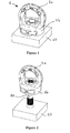
- the lifting hook comprises a hooking element 1 comprising an eyebolt or loop 1 a intended to be coupled to lifting means, such as ropes, chains, hoists and the like.
- Said eyebolt 1 a is connected to a substantially cylindrical base element 1b having an axial, shaped through hole 1 c.
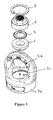
- Said axial hole 1 c has at the end thereof proximal to the base of said basic element 1b, a narrowing of the through hole made by a circular crown 1d which protrudes towards the inside of said base element 1 b constituting a resting surface for a bushing 2.
- the bushing 2 is also substantially cylindrical and has an axial hole, therefore said bushing has a substantially toroidal shape and has a lower diameter portion 2a adapted to be inserted, with a given clearance, in the lower diameter portion of said axial hole of the base element 1 b of the eyebolt 1, and a larger diameter portion 2b adapted to abut against the circular crown 1d integral with the base element 1 b.
- the bushing 2 may be accommodated in the hole 1c so that it firmly weighs on the crown 1d, and the dimensions of the profiles are such that once it has been correctly positioned within the cavity 1c the bushing protrudes underneath the lower surface of the base element 1 b.
- the lifting hook comprises, as mentioned, a hooking element 1 adapted to be connected by means of connection means 20 to the body 10 to be lifted.
- connection means 20 may advantageously comprise either a screw or a bolt, to which a nut will be associated.
- connection means consist of a bolt which enters the axial hole 1c of the hooking element and is then tightened with a threaded nut, indicated by reference numeral 4 in the figures.
- connection means comprise a screw provided with an appropriately shaped head, said screw being adapted to be inserted in the axial hole of the bushing 2, in turn positioned in the seat of the through hole 1c of the hooking element 1, said screw having an appropriately shaped head so as to reproduce the profile of the threaded nut 4, in order to correctly operate in tightening the connection means.
- the innovative feature which makes it possible to use the hooking element 1 according to the present invention either as “male” or as “female” is the presence of the bushing 2.
- the bushing 2 allows to lift the lower surface of the base element 1 b from the body to be lifted 10, regardless of the fact that the connection means consist of a bolt 20 and a threaded nut 4 as in the figures or of a screw provided with a head adapted to be inserted in the cavity 1c, which comes into contact with the lower surface of said head, according to an alternative embodiment, not shown in the appended figures.
- the presence of the bushing 2 allows to insert an anti-loosening device 3 either between said bushing 2 and said threaded nut 4 in the case of the female eyebolt shown in the drawings, or between said bushing 2 and said head, in the case of a screw for male eyebolt.
- connection of the hooking element 1 with the threaded element 20 is obtained by means of the threaded nut 4 which, as mentioned, is appropriately shaped.
- the anti-loosening device 3 e.g. consisting of a spring washer, is inserted between the lower surface of said nut 4 and the upper surface of said bushing 2.
- an appropriate seat 4a is obtained at the surface of the nut 4 intended to face the bushing 2, after assembly of the elements, also visible in figure 4 as a recess of the central part of the lower surface of the nut 4.
- the geometry of such seat 4a is such that, after tightening, the base of the nut 4 works in contact against the bushing 2, while the anti-loosening device 3 is compressed in its seat and prevents an unexpected loosening of the nut during use.
- an anti-loosening device may appropriately be provided between said bushing 2 and the lower surface of the head of a screw in case of male eyebolt.
- a stop device 5 e.g. a seeger ring
- a stop device 5 may advantageously be provided in a specific seat obtained in the inner surface of the hole 1 c of the base element 1 b, so as to constrain the nut 4, or the head of the screw in case of male eyebolt, the anti-loosening device 3 and the bushing 2 in the correct position inside the device.
- the stop device may consist of a plurality of protuberances obtained by plastic deformation on the top of the hooking element 1.
- the lifting hook according to the present invention is modular, because it allows to use the same hooking element or eyebolt either if a female lifting hook is made, i.e. if a threaded element must be locked by means of a nut housed in a specific seat obtained inside the hooking element, or if a male lifting hook is made, i.e. in which a screw with a head is inserted in the axial hole obtained in the hooking element or eyebolt so that the free end thereof can be freely fastened in the body to be lifted afterwards.
- the lifting hook according to the present invention allows to prevent unscrewing or loosening of the tightening of the connection means, also in this case for all system uses either as male eyebolt or as female eyebolt.
Landscapes
- Engineering & Computer Science (AREA)
- General Engineering & Computer Science (AREA)
- Mechanical Engineering (AREA)
- Hooks, Suction Cups, And Attachment By Adhesive Means (AREA)
- Load-Engaging Elements For Cranes (AREA)
Priority Applications (1)
| Application Number | Priority Date | Filing Date | Title |
|---|---|---|---|
| EP10425048A EP2361870A1 (de) | 2010-02-25 | 2010-02-25 | Ringbolzen mit Abschraubvorrichtung |
Applications Claiming Priority (1)
| Application Number | Priority Date | Filing Date | Title |
|---|---|---|---|
| EP10425048A EP2361870A1 (de) | 2010-02-25 | 2010-02-25 | Ringbolzen mit Abschraubvorrichtung |
Publications (1)
| Publication Number | Publication Date |
|---|---|
| EP2361870A1 true EP2361870A1 (de) | 2011-08-31 |
Family
ID=42321070
Family Applications (1)
| Application Number | Title | Priority Date | Filing Date |
|---|---|---|---|
| EP10425048A Withdrawn EP2361870A1 (de) | 2010-02-25 | 2010-02-25 | Ringbolzen mit Abschraubvorrichtung |
Country Status (1)
| Country | Link |
|---|---|
| EP (1) | EP2361870A1 (de) |
Cited By (8)
| Publication number | Priority date | Publication date | Assignee | Title |
|---|---|---|---|---|
| WO2014019614A1 (de) * | 2012-07-31 | 2014-02-06 | Pewag Austria Gmbh | Ringmutter |
| US8794886B1 (en) | 2013-03-11 | 2014-08-05 | Oshkosh Corporation | Cargo tie down |
| WO2015004126A1 (fr) | 2013-07-08 | 2015-01-15 | Intelprop S.A. | Point de levage tournant |
| US20150071732A1 (en) * | 2013-09-06 | 2015-03-12 | Yoke Industrial Corp. | Eyebolt |
| WO2017125492A1 (fr) * | 2016-01-20 | 2017-07-27 | Intelprop S.A. | Anneau de levage pivotant pour le levage de charges |
| EP3263505A1 (de) | 2016-06-30 | 2018-01-03 | Intelprop S.A. | Lastanzeigevorrichtung, insbesondere für einen hebering |
| US10207902B2 (en) * | 2016-09-01 | 2019-02-19 | Mjt Holdings, Llc | Load-mountable lift eye assembly |
| CN110626936A (zh) * | 2019-10-29 | 2019-12-31 | 法兰泰克重工股份有限公司 | 一种吊耳安装结构及起重机 |
Citations (7)
| Publication number | Priority date | Publication date | Assignee | Title |
|---|---|---|---|---|
| EP0654611A1 (de) | 1993-10-25 | 1995-05-24 | Rud-Kettenfabrik Rieger & Dietz Gmbh U. Co. | Ringschraube |
| US6017071A (en) * | 1997-11-17 | 2000-01-25 | Morghen; Manfred A. | Swiveling hoist assembly |
| DE10002899A1 (de) | 2000-01-14 | 2001-08-09 | Rud Ketten Rieger & Dietz | Ringmutter |
| FR2877933A1 (fr) * | 2004-11-17 | 2006-05-19 | Edmond Altabe | Anses de levage tournantes et articulables |
| FR2880084A1 (fr) * | 2004-12-23 | 2006-06-30 | Blaise Henrion | Dispositif de fixation du type anneau de levage |
| EP1961690A1 (de) * | 2007-02-26 | 2008-08-27 | Stamperia Carcano Giuseppe S.p.A. | Drehbare Tragöse |
| EP2182228A1 (de) * | 2008-10-30 | 2010-05-05 | Stamperia Carcano Giuseppe S.p.A. | Ösenbefestigungsvorrichtung |
-
2010
- 2010-02-25 EP EP10425048A patent/EP2361870A1/de not_active Withdrawn
Patent Citations (7)
| Publication number | Priority date | Publication date | Assignee | Title |
|---|---|---|---|---|
| EP0654611A1 (de) | 1993-10-25 | 1995-05-24 | Rud-Kettenfabrik Rieger & Dietz Gmbh U. Co. | Ringschraube |
| US6017071A (en) * | 1997-11-17 | 2000-01-25 | Morghen; Manfred A. | Swiveling hoist assembly |
| DE10002899A1 (de) | 2000-01-14 | 2001-08-09 | Rud Ketten Rieger & Dietz | Ringmutter |
| FR2877933A1 (fr) * | 2004-11-17 | 2006-05-19 | Edmond Altabe | Anses de levage tournantes et articulables |
| FR2880084A1 (fr) * | 2004-12-23 | 2006-06-30 | Blaise Henrion | Dispositif de fixation du type anneau de levage |
| EP1961690A1 (de) * | 2007-02-26 | 2008-08-27 | Stamperia Carcano Giuseppe S.p.A. | Drehbare Tragöse |
| EP2182228A1 (de) * | 2008-10-30 | 2010-05-05 | Stamperia Carcano Giuseppe S.p.A. | Ösenbefestigungsvorrichtung |
Cited By (13)
| Publication number | Priority date | Publication date | Assignee | Title |
|---|---|---|---|---|
| WO2014019614A1 (de) * | 2012-07-31 | 2014-02-06 | Pewag Austria Gmbh | Ringmutter |
| US9664224B2 (en) | 2012-07-31 | 2017-05-30 | Pewag Austria Gmbh | Ring nut |
| US8794886B1 (en) | 2013-03-11 | 2014-08-05 | Oshkosh Corporation | Cargo tie down |
| WO2015004126A1 (fr) | 2013-07-08 | 2015-01-15 | Intelprop S.A. | Point de levage tournant |
| DE212014000152U1 (de) | 2013-07-08 | 2016-02-22 | Intelprop S.A. | Drehbarer Hebering |
| US20150071732A1 (en) * | 2013-09-06 | 2015-03-12 | Yoke Industrial Corp. | Eyebolt |
| WO2017125492A1 (fr) * | 2016-01-20 | 2017-07-27 | Intelprop S.A. | Anneau de levage pivotant pour le levage de charges |
| LU92951B1 (fr) * | 2016-01-20 | 2017-08-07 | Intelprop S A | Point de levage pivotant pour le levage de charges |
| US10421644B2 (en) | 2016-01-20 | 2019-09-24 | Intelprop S.A. | Pivoting lifting ring for lifting loads |
| EP3263505A1 (de) | 2016-06-30 | 2018-01-03 | Intelprop S.A. | Lastanzeigevorrichtung, insbesondere für einen hebering |
| WO2018002136A1 (fr) | 2016-06-30 | 2018-01-04 | Intelprop S.A. | Dispositif de témoin de charge, en particulier pour un anneau de levage |
| US10207902B2 (en) * | 2016-09-01 | 2019-02-19 | Mjt Holdings, Llc | Load-mountable lift eye assembly |
| CN110626936A (zh) * | 2019-10-29 | 2019-12-31 | 法兰泰克重工股份有限公司 | 一种吊耳安装结构及起重机 |
Similar Documents
| Publication | Publication Date | Title |
|---|---|---|
| EP2361870A1 (de) | Ringbolzen mit Abschraubvorrichtung | |
| US3492033A (en) | Clevis assembly | |
| US2625005A (en) | Hoist hook assembly | |
| US6022164A (en) | Captive multi-position fixture | |
| US10759633B2 (en) | Rotating eye bolt assembly with lock mechanism | |
| EP3088769B1 (de) | Schwenkanordnungen | |
| US9726255B1 (en) | Shackle with self centering closure cross member | |
| EP2495459A1 (de) | Ankervorrichtung mit Lager zum Heben und kontinuierlichen Drehen, auch unter schwerer Last | |
| US10421644B2 (en) | Pivoting lifting ring for lifting loads | |
| US10202260B2 (en) | Rigging connector having combination hook and shackle mounting | |
| KR20120023073A (ko) | 요동 연결구 | |
| JP2010247992A (ja) | 連結器具 | |
| US9416847B2 (en) | Capture block assembly for retaining shackles | |
| US10112078B1 (en) | Step assembly with fall arrest capability including removable step | |
| US11162561B2 (en) | Heavy-duty shackle | |
| US20160375282A1 (en) | Step unit with fall arrest capability | |
| WO2017020284A1 (zh) | 一种止转套、紧固连接组件、紧固连接结构及安装方法 | |
| US20190128376A1 (en) | Shackle guard with tether | |
| EP2182228B1 (de) | Ösenbefestigungsvorrichtung | |
| US10054146B1 (en) | Shackle guard with tether | |
| US20220314896A1 (en) | Attachment system | |
| US20030031531A1 (en) | Lock nut arrangement | |
| US20240240697A1 (en) | Swivel connection device | |
| US10473188B2 (en) | Shackle guard and spacer with tether | |
| US20160096046A1 (en) | Step unit with fall arrest capability |
Legal Events
| Date | Code | Title | Description |
|---|---|---|---|
| PUAI | Public reference made under article 153(3) epc to a published international application that has entered the european phase |
Free format text: ORIGINAL CODE: 0009012 |
|
| AK | Designated contracting states |
Kind code of ref document: A1 Designated state(s): AT BE BG CH CY CZ DE DK EE ES FI FR GB GR HR HU IE IS IT LI LT LU LV MC MK MT NL NO PL PT RO SE SI SK SM TR |
|
| AX | Request for extension of the european patent |
Extension state: AL BA RS |
|
| STAA | Information on the status of an ep patent application or granted ep patent |
Free format text: STATUS: THE APPLICATION IS DEEMED TO BE WITHDRAWN |
|
| 18D | Application deemed to be withdrawn |
Effective date: 20120301 |